

Page 1
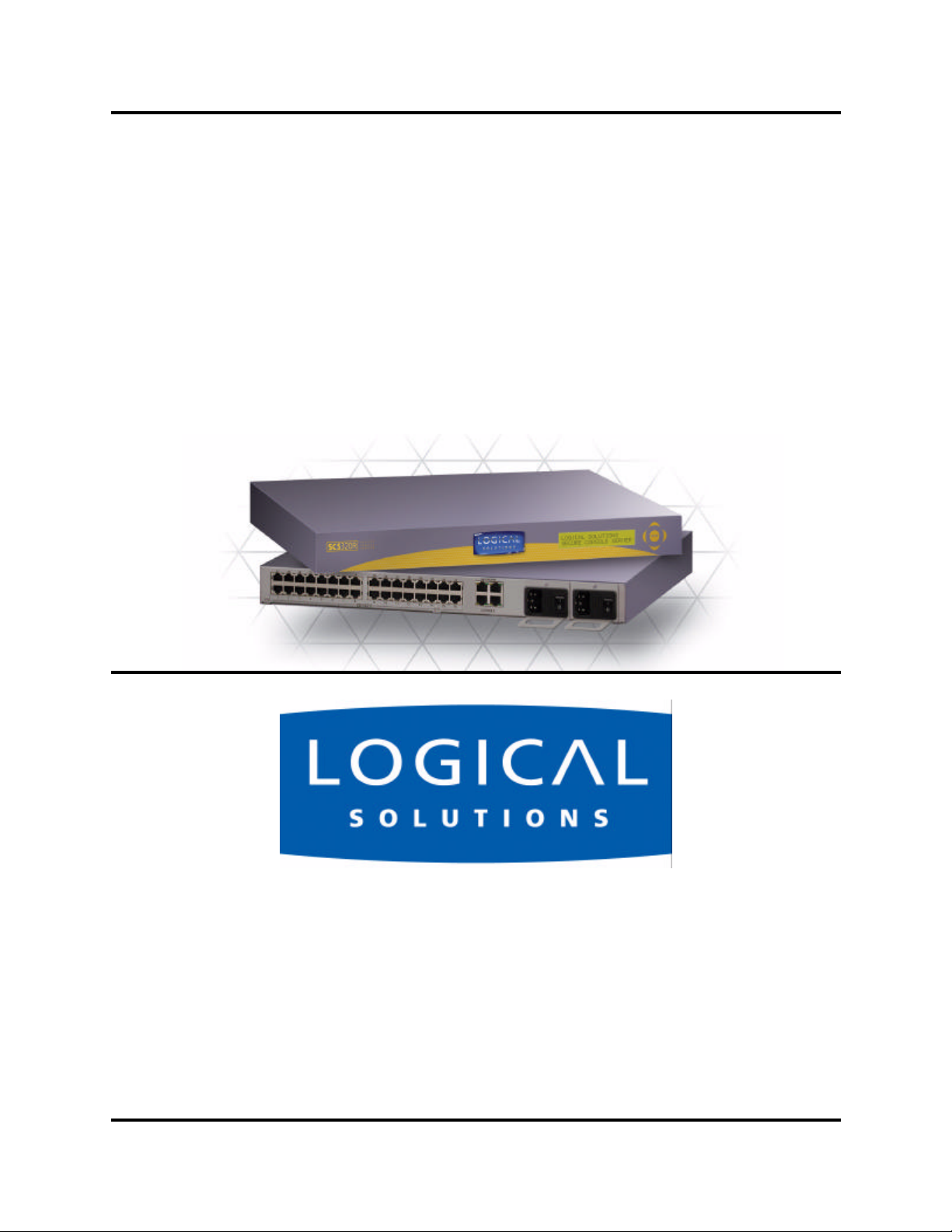
Secure Console Servers
SCS and SCS-R Models
Product Manual
Part Number MAN-000001
Revision C
Logical Solutions Inc.
100 Washington Street
Milford, Connecticut 06460 U.S.A.
Telephone (203) 647-8700
Fax (203) 783-9949
www.thinklogical.com
Page 2

Copyright Notice
Copyright © 2003 All Rights Reserved. Printed in the U.S.A.
Logical Solutions Incorporated
100 Washington Street
Milford, Connecticut 06460 U.S.A.
Telephone (203) 647-8700
All trademarks and services marks are property of their respective owners.
At Logical Solutions, we do our best to provide comprehensive information with
our products. In the event we have an error or oversight in this document, we’re sorry,
and we will do our best to address the issue in the next revision (if there is one). If you
have any issues or questions about the product or this documentation, please contact
our Product Support personnel. However, we cannot be held responsible for typos or
unintentional omissions from this manual.
Being a technology company, we are constantly looking for innovative ways to
make our products work for the advantage of our customers. It is important to use the
product manual that came with your system with that product. If you have any comments or suggestions for the product, please send your comments to our Product Support or our Sales personnel. Please see Section 11, How to Contact Logical, on page 81.
Document ID: MAN-000001
Subject: SCS160 / SCS320 / SCS480 / SCS160R / SCS320R
Revision: Rev. C, June 17, 2003. 90 pages in total.
Also available online as a PDF document at: www.thinklogical.com
SCS160 / SCS320 / SCS480 Page 2 www.thinklogical.com
SCS160R / SCS320R
Page 3

SECURE CO NSO LE S ERVERS
SCS160 / SCS320 / SCS480 / SCS160R / SCS320R Product Manual
1 Introduction - - - - - - - - - - - - - - - - - - - - - - 9
1.1 SCS Models Covered in this Manual - - - - - - - - - - - - - - 9
1.2 System Features - - - - - - - - - - - - - - - - - - - - - - - -10
1.3 Software Features - - - - - - - - - - - - - - - - - - - - - - -11
1.4 Hardware Features - - - - - - - - - - - - - - - - - - - - - - -11
1.4.1 SCS160R / SCS320R Hardware - - - - - - - - - - - - - - - -12
1.5 Technical Specifications - - - - - - - - - - - - - - - - - - - -13
2 Product Overview - - - - - - - - - - - - - - - - - - - 15
2.1 Intended Application - - - - - - - - - - - - - - - - - - - - - -15
2.2 System Chassis- - - - - - - - - - - - - - - - - - - - - - - - -16
2.2.1 SCS160 / SCS320 / SCS480 - - - - - - - - - - - - - - - - - -16
2.2.2 SCS160R / SCS320R - - - - - - - - - - - - - - - - - - - - -16
2.3 Connecting to the SCS - - - - - - - - - - - - - - - - - - - - -17
2.3.1 Serial Devices - - - - - - - - - - - - - - - - - - - - - - - - -17
2.3.1.1 Break Safe - - - - - - - - - - - - - - - - - - - - - - - - - -17
2.3.2 IP Network - - - - - - - - - - - - - - - - - - - - - - - - - - -18
2.3.3 AC Power - - - - - - - - - - - - - - - - - - - - - - - - - - -18
2.3.3.1 SCS160 / SCS320 / SCS480 - - - - - - - - - - - - - - - - -18
2.3.3.2 SCS160R / SCS320R - - - - - - - - - - - - - - - - - - - -18
2.4 User Access Control - - - - - - - - - - - - - - - - - - - - - -19
2.4.1 User Sessions - - - - - - - - - - - - - - - - - - - - - - - - -19
2.5 Port Buffers - - - - - - - - - - - - - - - - - - - - - - - - - - -19
3 Installation - - - - - - - - - - - - - - - - - - - - - - - 21
3.1 Mounting the SCS- - - - - - - - - - - - - - - - - - - - - - - -21
3.1.1 Rack Mount or Desktop - - - - - - - - - - - - - - - - - - - -21
3.1.2 Front Panel Display and Buttons - - - - - - - - - - - - - - - -22
3.1.3 It’s Convection Cooled - - - - - - - - - - - - - - - - - - - - -22
tel (203) 647-8700 Page 3 Product Manual - MAN-000001C
Page 4

3.2 Connections - - - - - - - - - - - - - - - - - - - - - - - - - -22
3.2.1 Power - - - - - - - - - - - - - - - - - - - - - - - - - - - - -22
3.2.2 AC Input - - - - - - - - - - - - - - - - - - - - - - - - - - - -22
3.2.3 Connecting to the Network Port - - - - - - - - - - - - - - - - -23
3.2.3.1 SCS160R / SCS320R Dual NIC Interface - - - - - - - - - - -23
3.2.4 Connect your Console - - - - - - - - - - - - - - - - - - - - -23
3.2.4.1 SCS160R / SCS320R Dual Console Interface - - - - - - - -24
3.2.5 Connect to the Ports - - - - - - - - - - - - - - - - - - - - - -24
3.2.5.1 Port Adapters - - - - - - - - - - - - - - - - - - - - - - - -24
3.2.5.2 Serial Port Pinout - - - - - - - - - - - - - - - - - - - - - -25
3.3 SCS160R / SCS320R Power Modules - - - - - - - - - - - - - -26
3.3.1 AC Power Module Replacement - - - - - - - - - - - - - - - -27
4 Initial Configuration - - - - - - - - - - - - - - - - - - 29
4.1 Default Configuration - - - - - - - - - - - - - - - - - - - - - -29
4.2 Initial System Security Concerns - - - - - - - - - - - - - - - -30
4.3 Initial Connection via Network - - - - - - - - - - - - - - - - -30
4.3.1 Network Connection Requirements - - - - - - - - - - - - - - -30
4.3.2 Route via Linux workstation - - - - - - - - - - - - - - - - - -30
4.3.3 Route via Windows workstation - - - - - - - - - - - - - - - - -31
4.4 Front Panel Network Setup - - - - - - - - - - - - - - - - - - -33
4.4.1 Front Panel Edit Mode - - - - - - - - - - - - - - - - - - - - -33
4.4.1.1 Start Front Panel Edit Mode - - - - - - - - - - - - - - - - -34
4.4.1.2 Program Network - - - - - - - - - - - - - - - - - - - - - -35
5 System Administration - - - - - - - - - - - - - - - - - 41
5.1 SCS Systems are Linux-based - - - - - - - - - - - - - - - - -41
5.1.1 Linux General Public License- - - - - - - - - - - - - - - - - -41
5.1.2 Understanding Linux - - - - - - - - - - - - - - - - - - - - - -41
5.1.3 SCS System Architecture - - - - - - - - - - - - - - - - - - -42
5.2 Initial Sysadmin Access - - - - - - - - - - - - - - - - - - - -42
5.2.1 Connect using a Terminal - - - - - - - - - - - - - - - - - - -42
5.2.2 Log In as root - - - - - - - - - - - - - - - - - - - - - - - - -43
5.2.3 Enter Commands - - - - - - - - - - - - - - - - - - - - - - -43
5.2.4 Log Out - - - - - - - - - - - - - - - - - - - - - - - - - - - -43
SCS160 / SCS320 / SCS480 Page 4 www.thinklogical.com
SCS160R / SCS320R
Page 5

SECURE CO NSO LE S ERVERS
5.3 Default Services - - - - - - - - - - - - - - - - - - - - - - - -44
5.3.1 Configure the Services - - - - - - - - - - - - - - - - - - - - -44
5.3.1.1 Configure the Services - - - - - - - - - - - - - - - - - - - -45
6 Commands - - - - - - - - - - - - - - - - - - - - - - - 47
6.1 System Commands - - - - - - - - - - - - - - - - - - - - - - -47
6.2 save Command - - - - - - - - - - - - - - - - - - - - - - - - -48
6.3 reboot - - - - - - - - - - - - - - - - - - - - - - - - - - - - - -48
6.4 poweroff - - - - - - - - - - - - - - - - - - - - - - - - - - - -49
6.5 Other Linux Commands - - - - - - - - - - - - - - - - - - - -49
6.6 Change Logging Level - - - - - - - - - - - - - - - - - - - - -51
7 System Administration - - - - - - - - - - - - - - - - - 53
7.1 Security - - - - - - - - - - - - - - - - - - - - - - - - - - - - -53
7.2 Change Network Address- - - - - - - - - - - - - - - - - - - -53
7.2.1 Run netconfig - - - - - - - - - - - - - - - - - - - - - - - - -54
7.2.2 More Than One Nameserver - - - - - - - - - - - - - - - - - -55
7.3 Change Hostname - - - - - - - - - - - - - - - - - - - - - - -56
7.4 Time Configuration - - - - - - - - - - - - - - - - - - - - - - -56
7.5 Change NIC Speed - - - - - - - - - - - - - - - - - - - - - - -56
7.6 Configure Authentications - - - - - - - - - - - - - - - - - - -57
7.7 Front Panel Display Options - - - - - - - - - - - - - - - - - -57
7.7.1 Display Mode Parameters - - - - - - - - - - - - - - - - - - -58
7.7.1.1 Edit - - - - - - - - - - - - - - - - - - - - - - - - - - - - -58
7.7.1.2 View - - - - - - - - - - - - - - - - - - - - - - - - - - - - -58
7.7.1.3 LINE_1 - - - - - - - - - - - - - - - - - - - - - - - - - - -59
7.7.1.4 LINE_2 - - - - - - - - - - - - - - - - - - - - - - - - - - -59
7.7.1.5 Display OFF - - - - - - - - - - - - - - - - - - - - - - - - -59
7.8 Network Time Service - - - - - - - - - - - - - - - - - - - - -59
7.8.1 Configure NTP - - - - - - - - - - - - - - - - - - - - - - - - -60
7.8.2 Start the NTP Service - - - - - - - - - - - - - - - - - - - - -60
tel (203) 647-8700 Page 5 Product Manual - MAN-000001C
Page 6

7.9 NIS and User Port Permissions- - - - - - - - - - - - - - - - -61
7.9.1 User Port Control - - - - - - - - - - - - - - - - - - - - - - -61
7.9.2 Changing Serial Port settings- - - - - - - - - - - - - - - - - -61
7.9.3 NIS Port Access - - - - - - - - - - - - - - - - - - - - - - - -62
7.9.4 User Names and Groups - - - - - - - - - - - - - - - - - - - - 63
7.9.5 NIS Database file - - - - - - - - - - - - - - - - - - - - - - -63
7.9.6 NIS Make file - - - - - - - - - - - - - - - - - - - - - - - - -64
7.9.7 NIS Configuration File - - - - - - - - - - - - - - - - - - - - -64
7.10 NFS - - - - - - - - - - - - - - - - - - - - - - - - - - - - - - -64
7.10.1 Remote NFS Directory - - - - - - - - - - - - - - - - - - - - -64
7.11 SNMP - - - - - - - - - - - - - - - - - - - - - - - - - - - - - -65
7.11.1 Start SNMP - - - - - - - - - - - - - - - - - - - - - - - - - -65
7.12 syslog - - - - - - - - - - - - - - - - - - - - - - - - - - - - - -65
7.13 Timeouts - - - - - - - - - - - - - - - - - - - - - - - - - - - -66
8 Administering Users - - - - - - - - - - - - - - - - - - 67
8.1 User Setup - - - - - - - - - - - - - - - - - - - - - - - - - - -67
8.1.1 adduser - - - - - - - - - - - - - - - - - - - - - - - - - - - -68
8.1.2 edituser - - - - - - - - - - - - - - - - - - - - - - - - - - - -68
8.1.3 deluser - - - - - - - - - - - - - - - - - - - - - - - - - - - -68
8.1.4 Other Editing Commands- - - - - - - - - - - - - - - - - - - -68
8.1.4.1 editbrk <name> - - - - - - - - - - - - - - - - - - - - - - -69
8.1.4.2 editesc <name> - - - - - - - - - - - - - - - - - - - - - - -69
9 User Operations - - - - - - - - - - - - - - - - - - - - 71
9.1 User Accounts - - - - - - - - - - - - - - - - - - - - - - - - -71
9.1.1 SCS Users - - - - - - - - - - - - - - - - - - - - - - - - - - -71
9.1.2 root user - - - - - - - - - - - - - - - - - - - - - - - - - - - -71
9.2 Port Identities - - - - - - - - - - - - - - - - - - - - - - - - - -72
SCS160 / SCS320 / SCS480 Page 6 www.thinklogical.com
SCS160R / SCS320R
Page 7

SECURE CO NSO LE S ERVERS
9.3 What Can A User Do - - - - - - - - - - - - - - - - - - - - - -72
9.3.1 Access via Network - - - - - - - - - - - - - - - - - - - - - -72
9.3.2 ssh to a Port - - - - - - - - - - - - - - - - - - - - - - - - - -72
9.3.3 Access via Console Port - - - - - - - - - - - - - - - - - - - -72
9.3.4 Interactive Mode - - - - - - - - - - - - - - - - - - - - - - - -72
9.3.5 Break Sequence - - - - - - - - - - - - - - - - - - - - - - - -73
9.3.5.1 editbrk - - - - - - - - - - - - - - - - - - - - - - - - - - - -73
9.3.6 Escape Sequence - - - - - - - - - - - - - - - - - - - - - - -73
9.3.6.1 Edit Escape Sequence - - - - - - - - - - - - - - - - - - - -74
10 Regulatory & Safety - - - - - - - - - - - - - - - - - - 75
10.1 Safety Requirements - - - - - - - - - - - - - - - - - - - - - -75
10.1.1 Symbols found on the Product - - - - - - - - - - - - - - - - -75
10.1.2 Product Serial Number - - - - - - - - - - - - - - - - - - - - -75
10.1.3 Connection to the Product - - - - - - - - - - - - - - - - - - -75
10.2 Regulatory Compliance - - - - - - - - - - - - - - - - - - - - -76
10.3 North America - - - - - - - - - - - - - - - - - - - - - - - - -76
10.4 European Union- - - - - - - - - - - - - - - - - - - - - - - - -76
10.4.1 Declaration of Conformity - - - - - - - - - - - - - - - - - - -76
10.4.2 Standards With Which the Products Comply - - - - - - - - - -77
10.4.3 Supplementary Information - - - - - - - - - - - - - - - - - - -77
10.5 Australia & New Zealand - - - - - - - - - - - - - - - - - - - -78
10.6 Lithium Battery - - - - - - - - - - - - - - - - - - - - - - - - -78
10.7 SCS160R / SCS320R Power Modules - - - - - - - - - - - - - -79
11 How to Contact Logical - - - - - - - - - - - - - - - - 81
11.1 Customer Support - - - - - - - - - - - - - - - - - - - - - - -81
11.1.1 Website - - - - - - - - - - - - - - - - - - - - - - - - - - - -81
11.1.2 E-mail - - - - - - - - - - - - - - - - - - - - - - - - - - - - -82
11.1.3 Telephone - - - - - - - - - - - - - - - - - - - - - - - - - - -82
11.1.4 Fax - - - - - - - - - - - - - - - - - - - - - - - - - - - - - -82
11.2 Product Support - - - - - - - - - - - - - - - - - - - - - - - -83
11.2.1 Warranty- - - - - - - - - - - - - - - - - - - - - - - - - - - -83
11.2.2 Return Authorization - - - - - - - - - - - - - - - - - - - - - -83
11.2.3 Our Address - - - - - - - - - - - - - - - - - - - - - - - - - -83
tel (203) 647-8700 Page 7 Product Manual - MAN-000001C
Page 8

A File System - - - - - - - - - - - - - - - - - - - - - - 85
Read-Only vs. Read-Write - - - - - - - - - - - - - - - - - - -85
Read-Write Mode - - - - - - - - - - - - - - - - - - - - - - -85
LSI Directories - - - - - - - - - - - - - - - - - - - - - - - -86
B FAQ - - - - - - - - - - - - - - - - - - - - - - - - - - 87
How do I do this? - - - - - - - - - - - - - - - - - - - - - - - -87
Change Port Parameters - - - - - - - - - - - - - - - - - - -87
Change the Name of a Port - - - - - - - - - - - - - - - - - -87
View a Buffer - - - - - - - - - - - - - - - - - - - - - - - - -88
Control the Output of Debugging Messages - - - - - - - - - -88
SCS160 / SCS320 / SCS480 Page 8 www.thinklogical.com
SCS160R / SCS320R
Page 9
SCS Models Covered in this ManualSECURE CO NSO LE S ERVERS
1 Introduction
Introducing the Logical Solutions Inc. Secure Console Servers
1.1 SCS Models Covered in this Manual
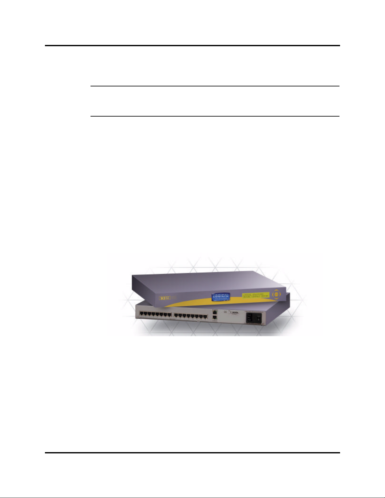
All Logical Solutions Secure Console Server (SCS) models covered in this manual
are similar in physical appearance, setup and functionality.
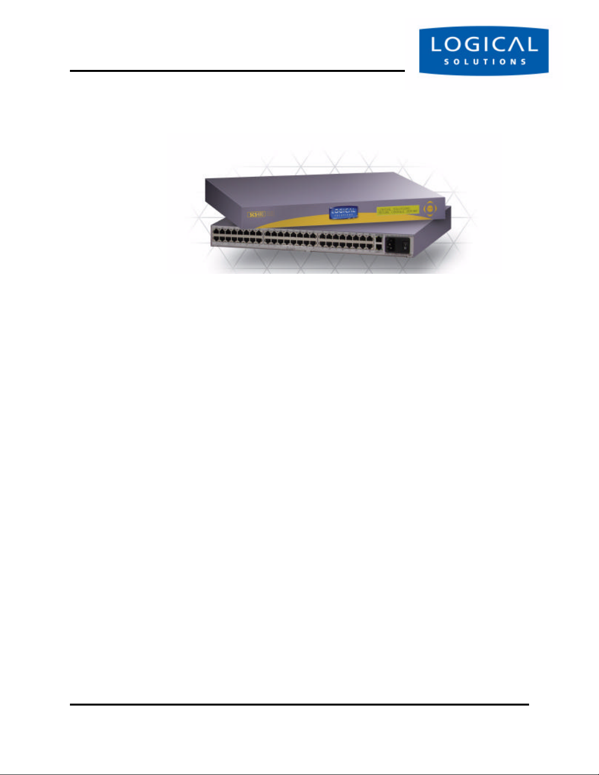
Figure 1.1 Logical Solutions SCS160, 16-Port Secure Console Server, front and rear view
• Model SCS160 - 16-Port 1U Secure Console Server (shown above)
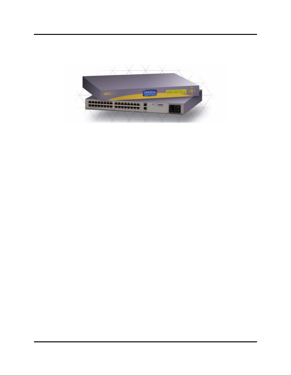
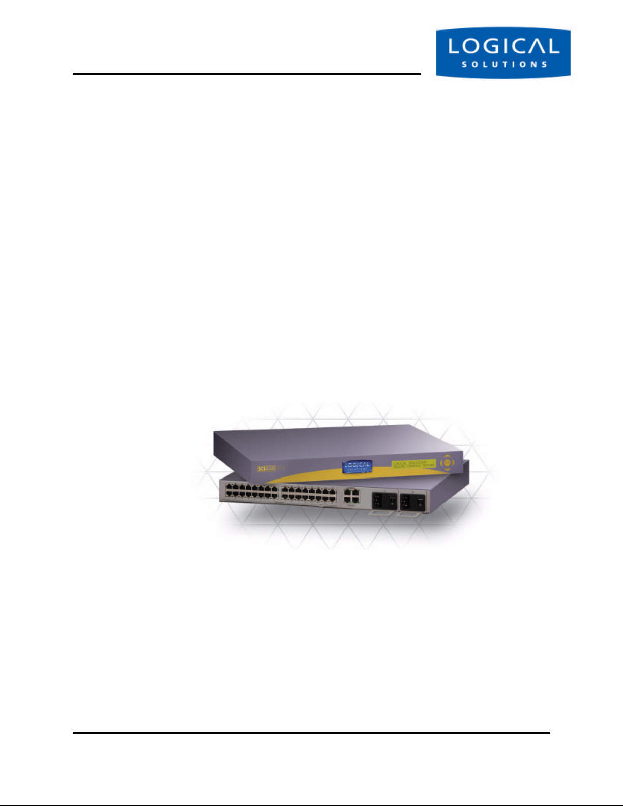
• Model SCS320 - 32-Port 1U Secure Console Server
• Model SCS480 - 48-Port 1U Secure Console Server
• Model SCS160R - 16-Port 1U Redundant Power Secure Console Server
• Model SCS320R - 32-Port 1U Redundant Power Secure Console Server
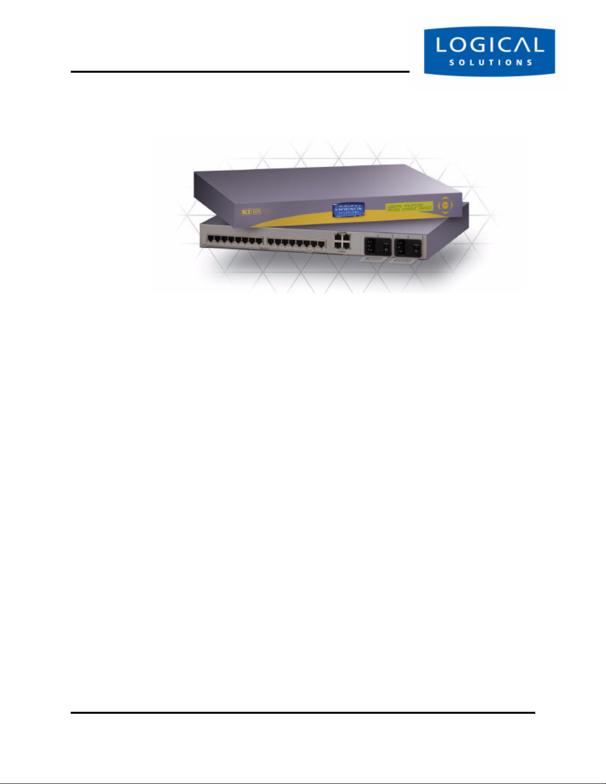
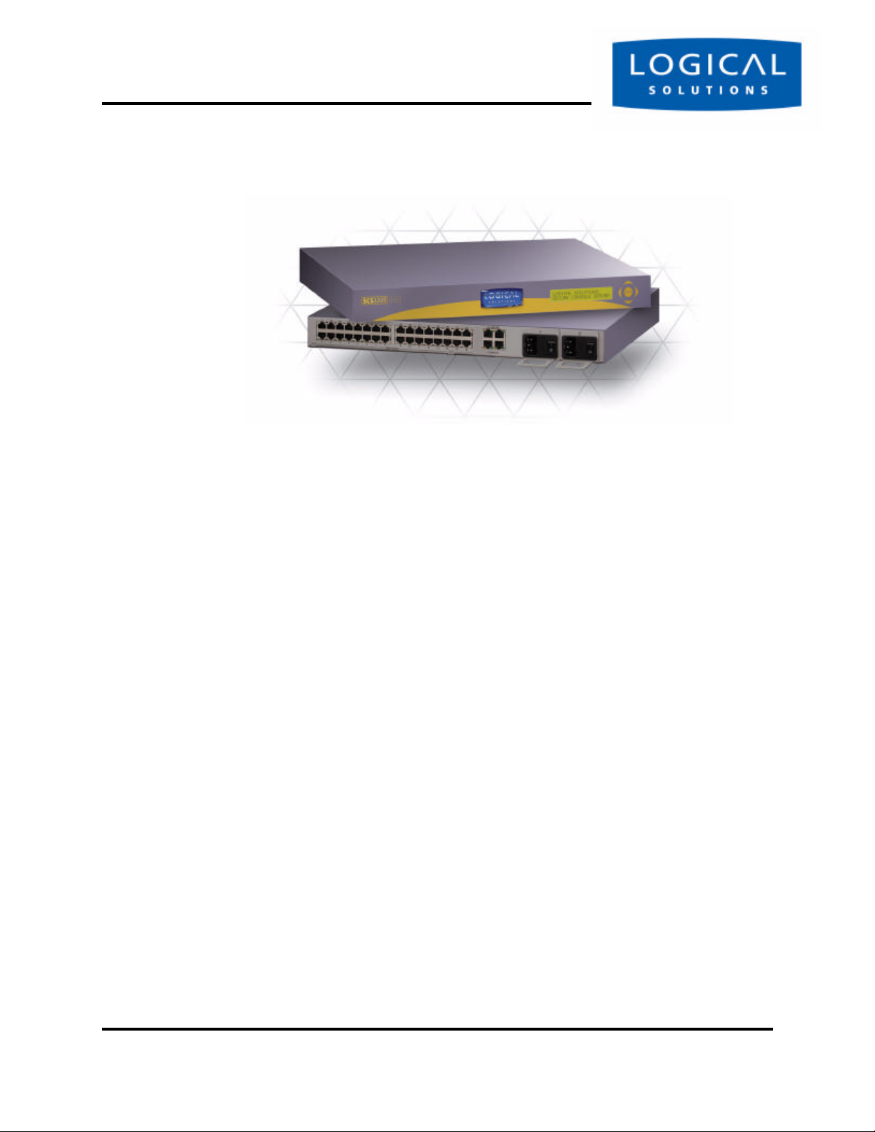
The SCS160R and SCS320R models are designed with dual hot-swappable AC
Power Modules which operate in a redundant manner, and also offer two Network
Ports and two Console port connections. The ‘R’ models are otherwise very similar to
the SCS160 and SCS320.
tel (203) 647-8700 Page 9 Product Manual - MAN-000001C
Page 10
Introduction
Figure 1.2 SCS160R Secure Console Server, front and rear views
shipped with regionally-appropriate AC power cordsets (otherwise similar to the
SCS160 / SCS320 / SCS480, respectively).
The following SCS models are available for International customers, and are
• Model SCS1601 - 16-Port 1U Secure Console Server, International
• Model SCS3201 - 32-Port 1U Secure Console Server, International
• Model SCS4801 - 48-Port 1U Secure Console Server, International
1.2 System Features
Each SCS system includes the following features:
• Linux operating system and command set
• Connect as many as 16, 32 or 48 EIA-232 serial console ports
• 10baseT / 100baseTX network compatible
• Preconfigured from the factory – two minutes from the box
• Uses OpenSSH (version 2) security
• Supports NFS and NIS
• Supports ssh to a Serial Port
• Break Safe - no undesired “break” signals are sent to attached servers
The SCS-R models also offer the following additional features:
• Dual Hot-Swappable Redundant AC Power Modules (rear access)
• Dual 10baseT / 100baseTX Network Port interfaces
• Dual Console Port interfaces (one DTE, one DCE)
• AC Power Monitoring for notification of AC Module outage
SCS160 / SCS320 / SCS480 Page 10 www.thinklogical.com
SCS160R / SCS320R
Page 11
Software FeaturesSECURE CO NSO LE S ERVERS
Figure 1.3 SCS320 Secure Console Server (32 Ports), front and rear views
1.3 Software Features
The SCS is designed with network administrators in mind. No need for special administration
tools, training or procedures. You know Linux, we run Linux.
• Open-source Linux Operating System (Red Hat distribution)
• Proprietary command-line options for SCS features follow the
familiar Linux / UNIX command formats for ease of administration
• Factory pre-configured to be operational out-of-the-box within a few minutes - the
sysadmin need only set the IP address and add users
The SCS line allows up to 250 simultaneous user sessions to access up to 48 serial ports. The
attached network components may be any variety of network center servers, workstations, or other
devices having a serial port that must be monitored.
1.4 Hardware Features
The SCS systems are designed for network data center applications, which tend to facilitate mounting a product in industry-standard 19-inch network equipment racks. The SCS may be placed on a shelf
or counter, instead. Each SCS operates independently and is accessible (setup by your System Administrator or “sysadmin”) using a secure network connection or a local serial terminal.
• Rack-mount (19 inch), 1U tall (1.75 in./ 4.5 cm) metal chassis
• 16, 32 or 48 serial Ports, using Category 5 (RJ45) connectors
• Front panel LCD with push buttons for network setup
• 10/100 BaseT Network Port for your network
• Console port (uses Category 5 connectors and wiring)
• Universal AC power input (100-240V, 50/60 Hz)
• Convection cooled in your rack enclosure
• 256KB-per-port Buffer memory for Port data
tel (203) 647-8700 Page 11 Product Manual - MAN-000001C
Page 12
Introduction
Figure 1.4 SCS480, 48-Port Secure Console Server, front and rear views
"listening" system that monitors the messages (ASCII data, server error information,
etc.) from the serial port of the device to which each Port is connected. The SCS captures the data by writing it to a port buffer, each of which can hold 256K bytes of data.
This buffered data gives the sysadmin a history of console port messages which can be
reviewed to help troubleshoot a problem with the connected device. After you’ve had
a networking device problem, and have access to its console port messages, the problem with your network equipment is easier to fix. Downtime in your network site can
be minimized by reviewing the buffered information, and then eliminating the cause
of the error messages.
port buffer to some other server (e.g., via NFS) in your network. This is important to
note since the Port data (buffered) is stored in RAM and will be lost if the SCS power
is turned off.
The SCS can help you troubleshoot your networking environment. The SCS is a
In most cases, the sysadmin has a method of saving the buffered data from each
1.4.1 SCS160R / SCS320R Hardware
The SCS ‘R’ models offer hardware redundancy for AC Power, Network and Console Ports. Having hot-swappable AC Power Supplies with discrete AC inputs allows
the customer to use redundant AC Power Sources to the SCS system, and if necessary,
they can field-replace a power module. The SCS-R models provide power supply status
to alert the system administrator in the event of a power failure from one of the power
supplies.
With Dual NIC inputs and Dual Console Port Inputs, the SCS160R and SCS320R
also provide additional benefits for sites needing these capabilities.
SCS160 / SCS320 / SCS480 Page 12 www.thinklogical.com
SCS160R / SCS320R
Page 13

Technical SpecificationsSECURE CO NSO LE S ERVERS
1.5 Technical Specifications
Each Logical Solutions SCS system is designed to the following specifications:
User Interface Linux command-line access via ssh or local console port
Backlit 2-line front-panel LCD display shows Network configuration
Five front-panel push buttons with UI for Network setup
Serial Interface
(Ports)
Serial Interface
(Console)
Network interface
(Network)
CPU & Memory AMD SC520 CPU, operating at 133 MHz
Power Supply Universal AC Power Input, 100-240VAC 50/60 Hz, 0.5A each input
Dimensions 1U, 1.75 in x 17.25 in x 14.75 in (4.5 cm x 43.8 cm x 37.5 cm)
[SCS160 = 16 Ports; SCS320 = 32 Ports; SCS480 = 48 Ports]
RJ45-type 8-conductor connector (DTE or DCE; software selectable)
Data rate is software selectable from 300 baud to 115KBaud
Software selectable EIA-232 parameters
256KB FIFO Buffer in RAM (per Port)
160/320/480: RJ45-type 8-conductor connector (DCE configuration)
160R/320R: Dual RJ45-type 8-conductor connector - one DTE, one DCE
Data rate is software selectable from 300 baud to 115KBaud
Software selectable EIA-232 parameters
160/320/480: 10/100 BaseT RJ45 8-conductor Ethernet
160R/320R: Dual 10/100 BaseT RJ45 8-conductor Ethernet
TCP/IP
256MB Compact Flash (CF) memory (non-volatile)
128MB RAM for real time use
IEC-type regional cordset(s) included
Weight 4.5 kg (10 lbs)
Temperature Operating: 0 to 50 °C (32 to 122 °F), 30 to 90% RH, non-condensing
Storage: -20 to 70 °C (-4 to 158 °F), 10 to 90% RH, non-condensing
Relative Humidity Operating: 10% to 90% non-condensing, 40% to 60% recommended
Storage: 10% to 90% non-condensing
tel (203) 647-8700 Page 13 Product Manual - MAN-000001C
Page 14
Introduction
Figure 1.5 SCS320R, showing front and rear views
SCS160 / SCS320 / SCS480 Page 14 www.thinklogical.com
SCS160R / SCS320R
Page 15

2 Product Overview
Optimize your System Administration and Network Resources
2.1 Intended Application
Intended ApplicationSECURE CO NSO LE S ERVERS
The Logical Solutions Secure Console Servers are used to securely monitor and
centrally manage up to 48 of your networking systems (servers, routers, switches, etc.).
They do so by monitoring the Console Port of your network center’s devices and systems. Each attached component must have an EIA-232 compatible serial console port.
The SCS160 and SCS160R support 16 ports, SCS320 and SCS320R support 32 ports,
and the SCS480 supports 48 ports. Security is maintained through encryption and user
passwords.
The SCS160R and SCS320R systems are used where redundant power concerns
exist, where hot-swap replacement of Power Modules is a concern, or where more than
one Network connection or more than one Console Port connection are required.
User accounts are set up by the root user, who acts as the system administrator of
the SCS. A user can access the attached servers using commands from a local terminal,
or through an ssh-protocol (secure) network connection. In order to interact with a
device, the user must have rights for read, review or write access to that port.
Users can interact with each of the attached network devices by logging into the
SCS, and entering the connect command and the Port number or Port name at the
command prompt; the SCS acts as a conduit for the connection but does not interfere.
When the user is not interacting with a network system, the SCS can log the output of
the Console port to a file, so that data may be reviewed later.
User commands are discussed in Section 9, User Operations, beginning on page 71.
tel (203) 647-8700 Page 15 Product Manual - MAN-000001C
Page 16
Product Overview
2.2 System Chassis
Each SCS is housed in the rack-mountable metal chassis. Vents are found on both
sides of the chassis, and 3-position rack mount brackets are provided and removable.
The front panel of the SCS features a two-line backlit LCD display with push buttons.
2.2.1 SCS160 / SCS320 / SCS480
Each SCS chassis has rear-panel connections for 16, 32 or 48 serial ports, one Console port, one Network port, and power. The SCS has a built-in universal AC power
supply. A rear-panel power switch and protective fuse is provided.
2.2.2 SCS160R / SCS320R
Each SCS-R chassis has rear-panel connections for 16 or 32 serial ports, two Console ports, two Network ports, and two hot-swappable Universal AC Power Modules,
each with its own Power switch and protective fuse. Each Power Module is secured
with a single screw into the back panel.
Figure 2.1 SCS320R Chassis Views; Power Supplies on right rear side of chassis
SCS160 / SCS320 / SCS480 Page 16 www.thinklogical.com
SCS160R / SCS320R
Page 17
Connecting to the SCSSECURE CO NSO LE S ERVERS
2.3 Connecting to the SCS
All physical connections to the product are made to the rear panel using industrystandard cabling and connectors (purchased separately). All serial connections and network connections use conventional Category 5 cabling having RJ45 jacks. AC Power
is connected using an IEC cordset, one of which is provided with each SCS system.
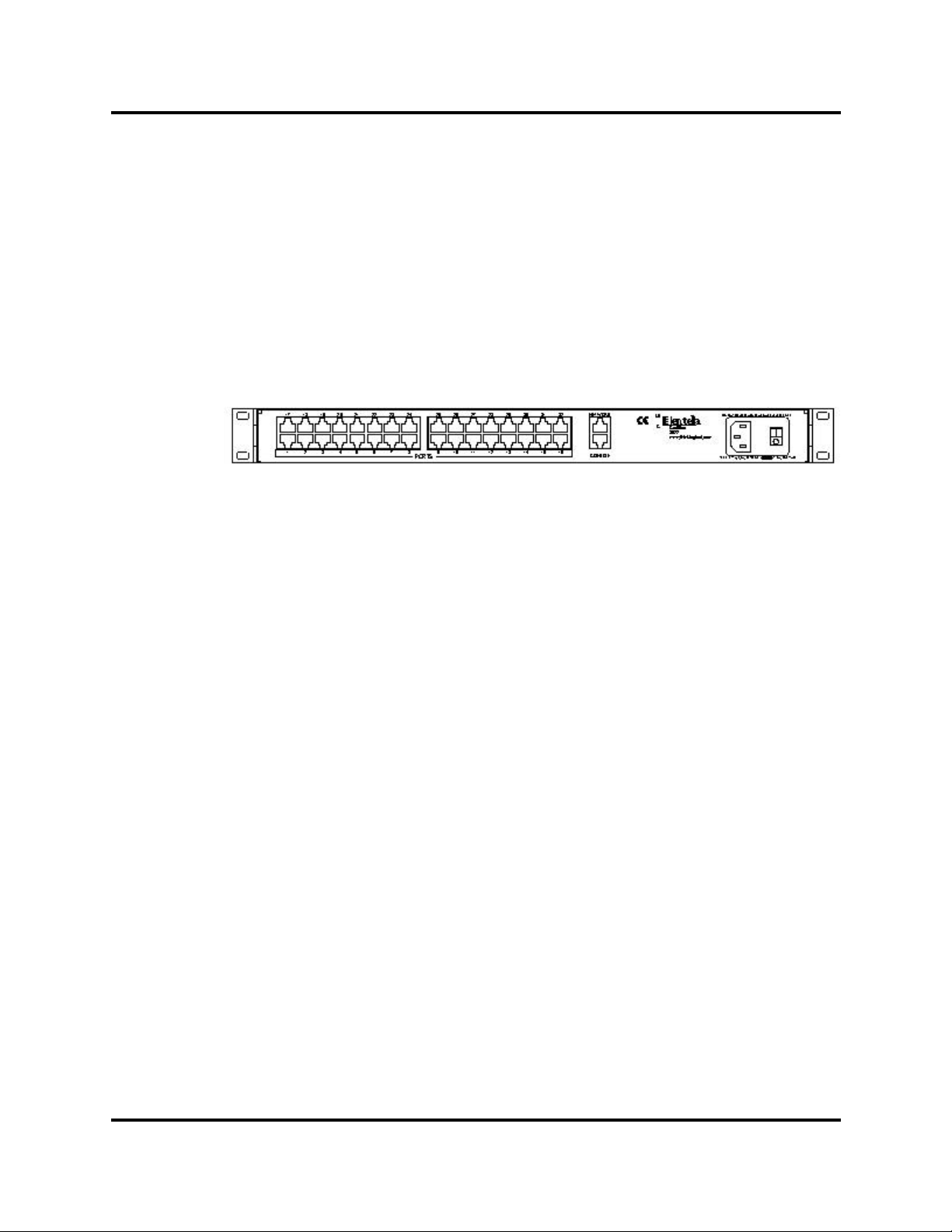
Figure 2.2 Rear View of SCS320 Chassis, showing all Connections
Serial Ports (32) 10/100 BaseT Network
Console Port AC Power
Other SCS models are similar, offering a different number of Port connectors. The
SCS-R models also have dual NIC, dual Console Ports and dual Power inputs. The
rack-mount brackets, shown on each side, may be removed if desired.
2.3.1 Serial Devices
All network components attached to both the Ports and the Console port must be
compatible with the EIA-232 standard. Regular fully-pinned Category 5 cabling with
RJ45 connectors are used for the Port connections and for the Console Port.
System ports (numbered 1 through 48) are default-configured as DCE data ports,
and support a range of baud rates from 300 Baud to 115.2K Baud. All Port parameters,
including DTE or DCE type and other data parameters are configurable on a per-port
basis. Each port may also be assigned a unique name: default port names are port1
through port48 , respectively.
2.3.1.1 Break Safe
The Logical Solutions SCS systems are “break-safe”, meaning that they will not
send a ‘break’ command or other data on the serial ports connected to your servers,
unless initiated by a user. A ‘break’ signal might cause problems with your servers.
tel (203) 647-8700 Page 17 Product Manual - MAN-000001C
Page 18

Product Overview
2.3.2 IP Network
The SCS network interface is an auto-sensing 10 BaseT/100 BaseTX network connector (equipped with an RJ45 jack with dual LEDs) for use with a conventional TCP/
IP network using standard RJ45 Category 5 cables. A default IP address is coded into
the system (10.9.8.7), however the network settings should be configured by your sys-
tem administrator to be suitable for your site’s requirements and unique equipment.
The SCS products are preconfigured for ssh (secure) access.
2.3.3 AC Power
Note
The SCS-R models offer two independent network interface ports.
Only the first port (NETWORK 1) is enabled by default.
2.3.3.1 SCS160 / SCS320 / SCS480
A single IEC-type power entry module is located on the rear of the chassis. The
power entry module incorporates a replaceable protective fuse (2A) and an On/Off
switch. An IEC cordset is provided with each SCS chassis. Connect the cordset to a
local AC power source. Turn the power switch on when appropriate.
2.3.3.2 SCS160R / SCS320R
Two removable AC Power Modules are found on the rear of the chassis, identified
as “Left” and “Right” if looking at the rear of the chassis. Either AC module will fully
support the system, and if both are turned on, they operate redundantly. The SCS-R
systems have an AC Power Monitoring capability to alert the system administrator in
the event of an AC Power outage from one of the modules.
Each AC Module has an IEC-type power entry module. The power entry module
incorporates a replaceable protective fuse (2A) and an On/Off switch. Two IEC cordsets are provided with each SCS-R chassis. Connect each cordset to a local AC power
source. Turn the power switch on (I) for each module when appropriate.
Caution
During replacement of a module, it is important to first turn the faulty
module Off, then remove its power cord, BEFORE youremove the
screw to allow the module to be pulled out. The potential for handling
hazardous voltages could exist otherwise.
SCS160 / SCS320 / SCS480 Page 18 www.thinklogical.com
SCS160R / SCS320R
Page 19

User Access ControlSECURE CO NSO LE S ERVERS
2.4 User Access Control
Access to a Port is controlled on a per-user basis via a user profile, which is stored
as a file on the local SCS. This profile is created by the root user using the command
‘adduser’. See Section 8.1.1, adduser, on page 68.
2.4.1 User Sessions
Each SCS supports up to 250 simultaneous user sessions. This is possible since a
user can generate multiple sessions. This number of sessions is perceived to be far
greater than would be needed in most SCS product applications.
2.5 Port Buffers
The Secure Console Servers provide real-time serial port data buffering. Each Port
buffer stores up to 256 KB of data in a buffer, held in RAM in a separate file. This
provides hundreds of pages of port data for each attached device, which can be
reviewed at a later time. The data may be viewed while users are not interacting with
the attached port. Port buffers are enabled by default.
tel (203) 647-8700 Page 19 Product Manual - MAN-000001C
Page 20

Product Overview
For Your Notes
SCS160 / SCS320 / SCS480 Page 20 www.thinklogical.com
SCS160R / SCS320R
Page 21

3 Installation
Place it in your Rack. Connect the Cat5 cables to the Ports. Plug it in.
3.1 Mounting the SCS
Mounting the SCSSECURE CO NSO LE S ERVERS
You may choose to rack mount your SCS unit(s) or place them on a shelf. The
front panel display should be visible and front panel buttons need only be accessible
for the initial setup of the system. All connections are made to the rear of the chassis.
3.1.1 Rack Mount or Desktop
The SCS products may be installed either in an EIA-standard 19-inch rack (1U tall)
or may be placed on a shelf or desktop. For shelf use, rubber feet are provided, and the
rack mount brackets may be removed. The SCS chassis does not need to be opened or
accessed. The sturdy metal case allows units to be stacked as required.
Note
Be sure to leave adequate ventilation room on both sides of the SCS
chassis, especially if units are being stacked.
The rack mount brackets are held on by 4 screws each. They may be positioned so
that the unit sits forward, flat or recessed in your rack. If the brackets removed or repositioned, it is not necessary to re-use the extra rack mount screws.
tel (203) 647-8700 Page 21 Product Manual - MAN-000001C
Page 22
Installation
It normally shows the current network settings and the date/time. The front panel buttons are only used during setup, or to review existing SCS settings.
Display Options, on page 57 for more information.
provided in an equipment rack. No fan means that it does not add to the ambient noise
in your equipment room. Be sure to not block the air vents on the sides of the unit,
and leave space on both sides. If mounted in an enclosed rack, it is recommended that
the rack have a ventilation fan to provide adequate airflow through the unit(s).
3.1.2 Front Panel Display and Buttons
The front-panel LCD display should be visible and accessible during system setup.
The LCD display can be customized by the root user. See Section 7.7, Front Panel
3.1.3 It’s Convection Cooled
The SCS does not require special cooling or ventilation other than what is normally
3.2 Connections
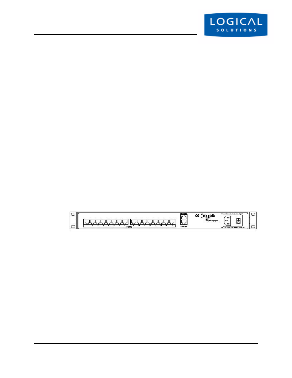
All connections are found on the rear of the SCS chassis. Each Port jack is clearly
labeled with the Port number.
Figure 3.1 SCS160 Chassis Rear View
3.2.1 Power
The SCS product has an internal universal AC power supply. Each SCS unit
requires approximately 15w of electrical power. The switching power supply accepts
nominal AC input voltage between 100-240 VAC with a frequency range of 50/60 Hz.
3.2.2 AC Input
A single IEC-type AC power entry module with an integral safety fuse and power
switch is found on the rear of the chassis for your AC power input. The power inlet to
the chassis uses a removable IEC-type cordset; one is provided with each system. Be
sure that your AC Power source is properly grounded.
SCS160 / SCS320 / SCS480 Page 22 www.thinklogical.com
SCS160R / SCS320R
Page 23

ConnectionsSECURE CO NSO LE S ERVERS
3.2.3 Connecting to the Network Port
Use a conventional fully-pinned Category 5 cable to connect your network connection to the NETWORK jack (RJ45) on the rear of the chassis.
The SCS’s network port (auto-selecting 10/100) allows remote access to the
attached networking components by the users and the sysadmin functions by the root
user. You can change the network parameters from the front panel of the SCS, or you
may ssh in to the default address and make changes using Linux commands.
3.2.3.1 SCS160R / SCS320R Dual NIC Interface
The SCS160R / SCS320R has dual Network Ports. The default configuration of
these Network Ports has the second Network Port disabled. Initially, only the first NIC
is functional (NETWORK 1 = device eth0). The second NIC (NETWORK 2 =
device eth1 ) must be enabled by the sysadmin.
To configure the second NIC, the sysadmin will log in and use one of the following
commands:
netconfig -d eth1
or
netconfig --device=eth1
Refer to Section 6 for other System Commands.
3.2.4 Connect your Console
The Console port is used for local access to the SCS. Connect your terminal or
computer with a terminal emulation package to the Console port. The SCS’s Console
port has a DCE configuration with adjustable parameters.
The default communication parameters for the Console port are:
• 9600 baud,
• 8 data bits,
• No parity,
• 1 stop bit, and
• Xon/Xoff flow control
Use a conventional fully-pinned Category 5 cable to connect your terminal or computer connection to the CONSOLE jack (RJ45) on the rear of the chassis.
tel (203) 647-8700 Page 23 Product Manual - MAN-000001C
Page 24

Installation
as DCE and the Console Port 2 pinned as DTE. The default configuration of these
Console Ports has the second Console Port disabled. To use the second Console port,
the root user must enable it.
SCS for consolidated system administration. Server Ports are individually configurable.
Consult your server documentation, as necessary.
data parameters and as DTE or DCE types.
3.2.4.1 SCS160R / SCS320R Dual Console Interface
The SCS160R / SCS320R has dual Console Ports, with the Console Port 1 pinned
The second console port is activated by editing the file /misc/inittab .
Refer to Section 6 for other System Commands.
3.2.5 Connect to the Ports
Any system (e.g., server, router, switch) with a serial port may be connected to the
The default communication parameters for the server Ports are:
• 9600 baud,
• 8 data bits,
• No parity,
• 1 stop bit,
• Xon/Xoff flow control, and
• Port type of DCE
Each Port can be individually configured for baud rates of 300-115,200 baud, the
Note
Ports may also be individually disabled, if desired.
3.2.5.1 Port Adapters
You may need to adapt the cable connection for your server device. Logical Solutions offers serial-to-RJ45 adapters for serial ports, both DB9 and DB25, for many
common network-equipment product applications.
SCS160 / SCS320 / SCS480 Page 24 www.thinklogical.com
SCS160R / SCS320R
Page 25
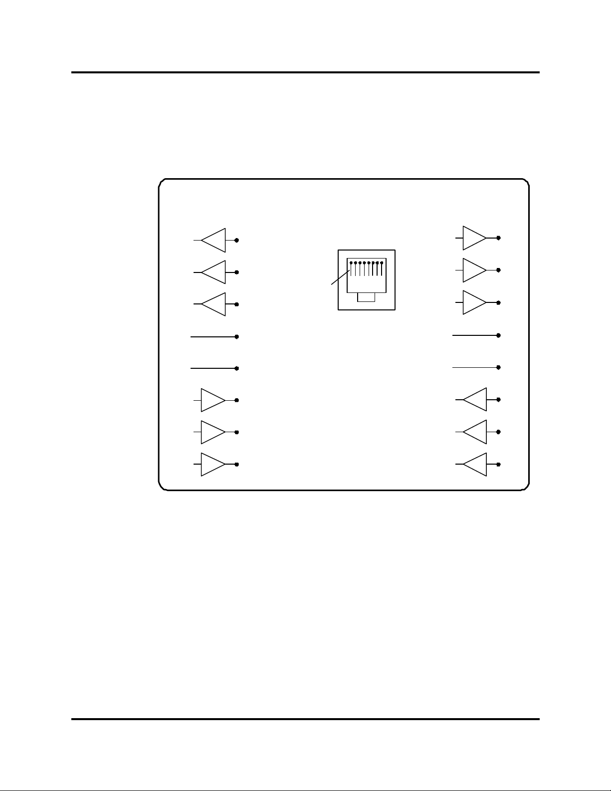
3.2.5.2 Serial Port Pinout
Figure 3.2 Serial Port Pinout - DCE (default) and DTE
ConnectionsSECURE CO NSO LE S ERVERS
EIA-232 Port
(DCE)
RTS
DTR
Tx
SG
SG
Rx
DSR
CTS
EIA-232 Port
(DTE)
1
2
RTS
DTR
1
2
Pin 1
3
Tx
EIA-232
4
5
6
RJ45-type Connector
SG
SG
Rx
Note: Default Setting
7
8
for Ports is DCE
DSR
CTS
3
4
5
6
7
8
Use a conventional fully-pinned Category 5 cable to connect the Console Port
from each of your networking components to the Port jacks on the rear of the chassis.
tel (203) 647-8700 Page 25 Product Manual - MAN-000001C
Page 26

Installation
which connect to the rear panel of the SCS chassis. Each Power Module has a power
entry connection with an IEC-type power connector. The SCS160R and SCS320R
have a Power Monitoring display shown on the front panel to indicate if one of the
power supplies is not powering the system (either AC power failure, a Module is turned
off, or the supply has failed).
the intended design is to have two AC power sources to keep your SCS system running
in the event one of your commercial AC sources fails. When both supplies are active,
they will share the system load. If one fails, the remaining supply takes the load.
3.3 SCS160R / SCS320R Power Modules
The SCS160R and 320R provide dual AC power inputs which are field-replaceable,
Note
The Power Module in the SCS160/320/480 is not field serviceable.
This option only applies to the SCS160R and SCS320R.
Each Power Module can support the SCS160R/SCS320R system fully, however
Figure 3.3 SCS Front Panel Display, Left AC Power Module Failed
Left Supply Failed
Tue Mar 18 15:43:07 2003
The SCS160R and SCS320R ships with two AC power cordsets, one for each module, to allow separate AC power source connection. Plug in the IEC connection to the
SCS Power Module, and connect the AC plug to an acceptable AC power source.
SCS160 / SCS320 / SCS480 Page 26 www.thinklogical.com
SCS160R / SCS320R
Page 27
SCS160R / SCS320R Power ModulesSECURE CO NSO LE S ERVERS
3.3.1 AC Power Module Replacement
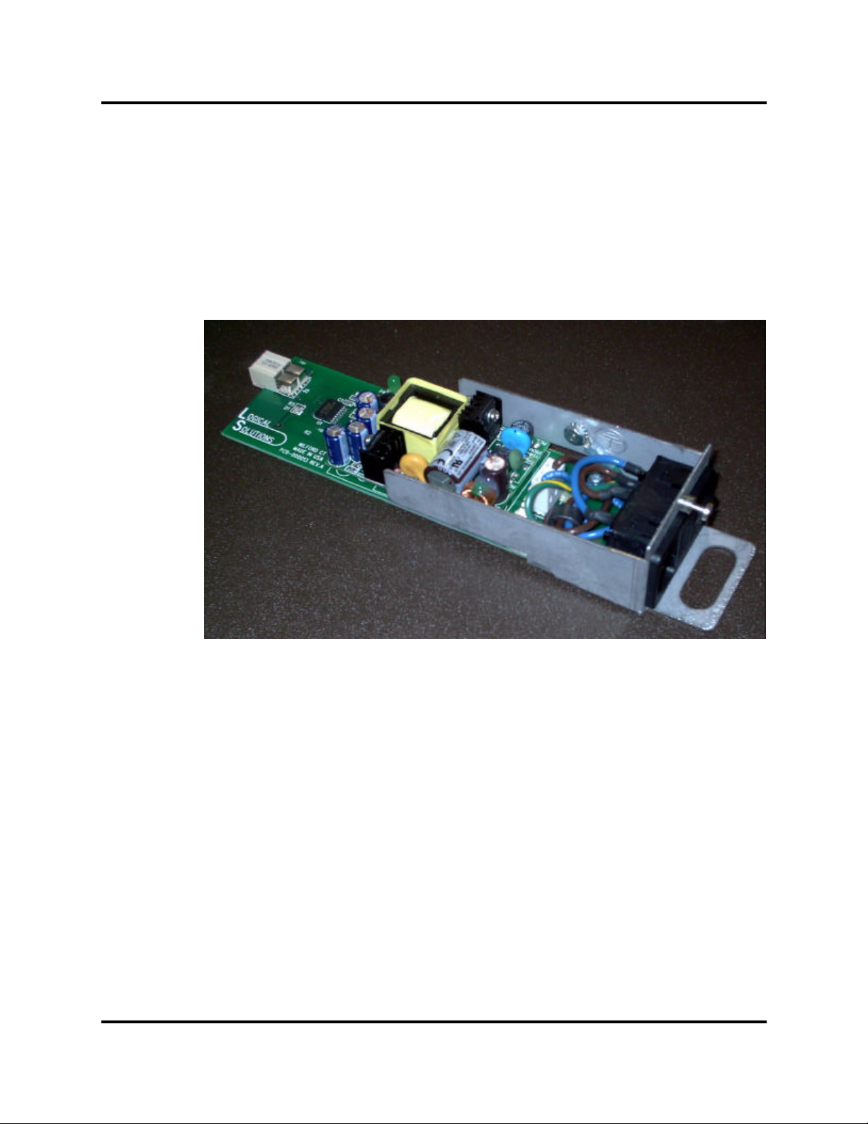
The AC Power Modules of the SCS160R and SCS320R may be hot-swapped if
necessary by a competent technician. Each slide-in power module is held in place with
a single screw and does not need to be removed except for replacement.
Figure 3.4 AC Power Module (shown removed from SCS-R)
If you need to replace one of the power supply modules, determine which module
has failed (left or right, if looking at the rear of the chassis) by reading the front panel
display. The module slides in from the rear of the chassis.
A single captive screw (visible from the rear of the chassis) holds the AC Power
Module in place, and also establishes a protective Earth ground connection for the system. Be certain to turn off the failed Power Module (switch on Module to O position),
then remove its power cord connection. You can then unscrew that Module and pull
it firmly from the chassis using the metal loop on the module.
tel (203) 647-8700 Page 27 Product Manual - MAN-000001C
Page 28
Installation
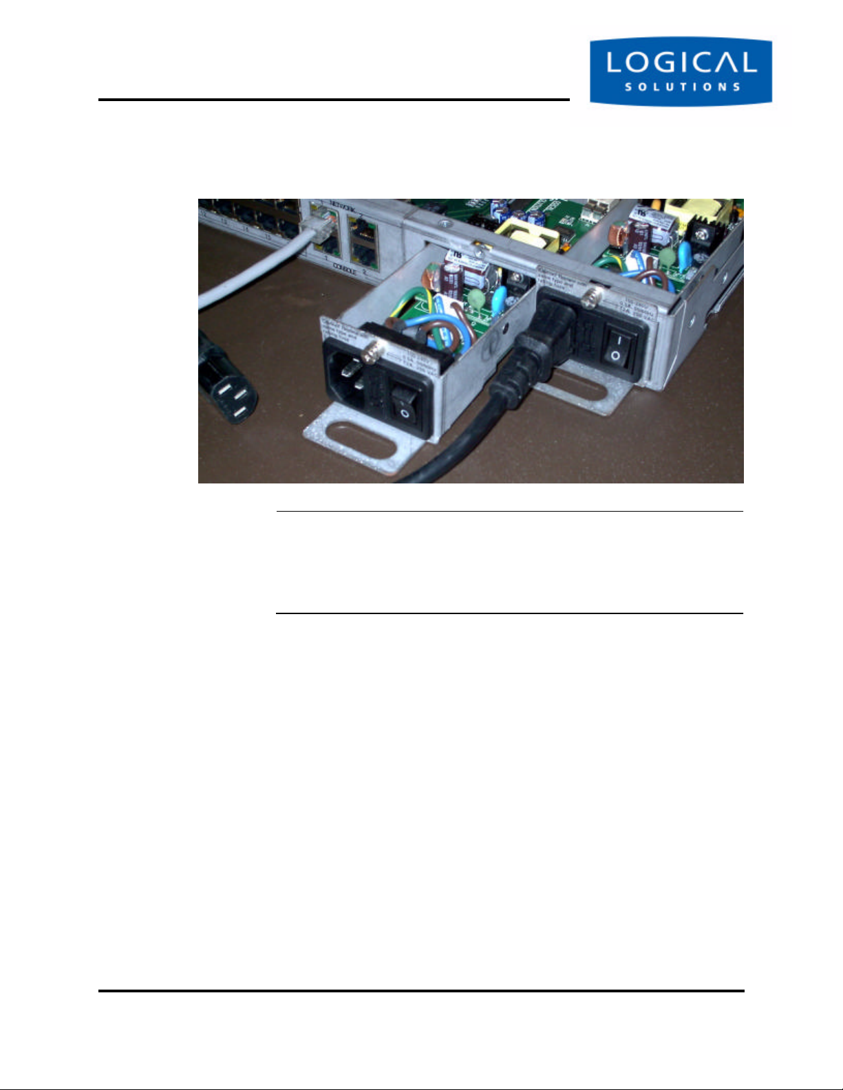
Figure 3.5 Replacing an AC Module (Left Module shown partially removed)
Note
To remove the AC Module, you only need to loosen the one captive
screw on the Module. You do not need to remove the chassis from
your rack, or remove the cover of the chassis for any reason. The
photo above shows the cover removed for clarity only.
Insert the replacement Power Module in its place (it will require a slight amount of
force to insert), and tighten the screw. After the screw is tightened, reconnect the IEC
cordset to the Module, and then you can turn the switch on the Module to the On (I)
position. When proper power is restored, the front panel display indicating a module
has failed will clear after a few moments.
SCS160 / SCS320 / SCS480 Page 28 www.thinklogical.com
SCS160R / SCS320R
Page 29

Default ConfigurationSECURE CO NSO LE S ERVERS
4 Initial Configuration
It’s Pre-Configured. Set your IP Address. Just Add Users.
4.1 Default Configuration
Out of the box, the SCS is pre-configured, ready to generate ssh keys, and has an
IP address set to a generic default value of 10.9.8.7 / NetMask 255.0.0.0. It is likely
that the sysadmin will want to change from this default IP address to your local IP
information. The sysadmin will only need to add user information specific to his site.
Note
The default IP address of the SCS is 10.9.8.7, with a default subnet
mask of 255.0.0.0.
When you first connect the unit to your network and turn the power on, it will take
about two minutes for the SCS to perform the initial ssh host key generation. The front
panel display will show the following display after the SCS’s power-up is complete and
the system is ready.
Figure 4.1 SCS Front Panel Display, default, normal mode shown
scs.localdomainname
Tue Mar 18 15:53:03 2003
The top line of the display is the SCS’s network and domain name, while the second line is a clock display showing day and date (initially set to Eastern Time Zone).
tel (203) 647-8700 Page 29 Product Manual - MAN-000001C
Page 30

Initial Configuration
4.2 Initial System Security Concerns
The first login will require several steps to fully secure the SCS.
When you first connect the SCS and turn it on, the SCS will build the ssh host keys
during the first two minutes of system startup. During this time, the front panel LCD
bottom line reads 'start sshd', and the console port reads 'Starting sshd'. The system is not dead or locked up, but is generating ssh host keys.
The root user should also configure the ntp and the ssh files.
4.3 Initial Connection via Network
You can access the SCS using ssh commands using your existing network. If you
add a route to your workstation, you can connect to the SCS via its default address.
4.3.1 Network Connection Requirements
• Have your SCS system connected to your network, and turn it on.
• Know your computer’s IP address
4.3.2 Route via Linux workstation
If using a Windows workstation, go to the next section.
If you are accessing the network from your Linux / Unix workstation, enter:
route add -net 10.9.8.7 netmask 255.255.255.255 gw <your workstation's IP address>.
Now, from your command line, to access the SCS system using ssh, enter:
You should be at the SCS’s root command prompt now.
You should change your SCS’s network address as one of the first changes you
make. See Section 7.2, Change Network Address, on page 53.
SCS160 / SCS320 / SCS480 Page 30 www.thinklogical.com
SCS160R / SCS320R
Page 31

Initial Connection via NetworkSECURE CO NSO LE S ERVERS
4.3.3 Route via Windows workstation
If using a Linux workstation, ignore this section.
If using Windows 9x/2000/XP, you can connect to the SCS using your networked
Windows PC and an ssh-capable terminal emulation package.
Note
If you don’t have an ssh-capable terminal package, try using PuTTY,
a freely-distributed package you can download at
http://www.chiark.greenend.org.uk/~sgtatham/putty/.
If you must use a Windows PC to login to the SCS, do the following:
1. Determine your PC’s IP network address.
One method: open a DOS prompt window and type ipconfig, and press Enter.
Your PC’s IP address is listed, among other things.
2. Add the route between the PC and the SCS.
From a DOS prompt, enter:
route add 10.9.8.7 mask 255.255.255.255 <workstation's IP
address> [press Enter]
3. Ping the SCS to be sure that your network connection is now functioning.
Verify that this route now functions by typing ping 10.9.8.7 at the DOS
prompt, and pressing Enter. Review the results for a positive response.
4. Connect to the SCS using your terminal package, using ssh.
Launch your terminal package, and connect to the default IP address of the SCS
of 10.9.8.7 using ssh.
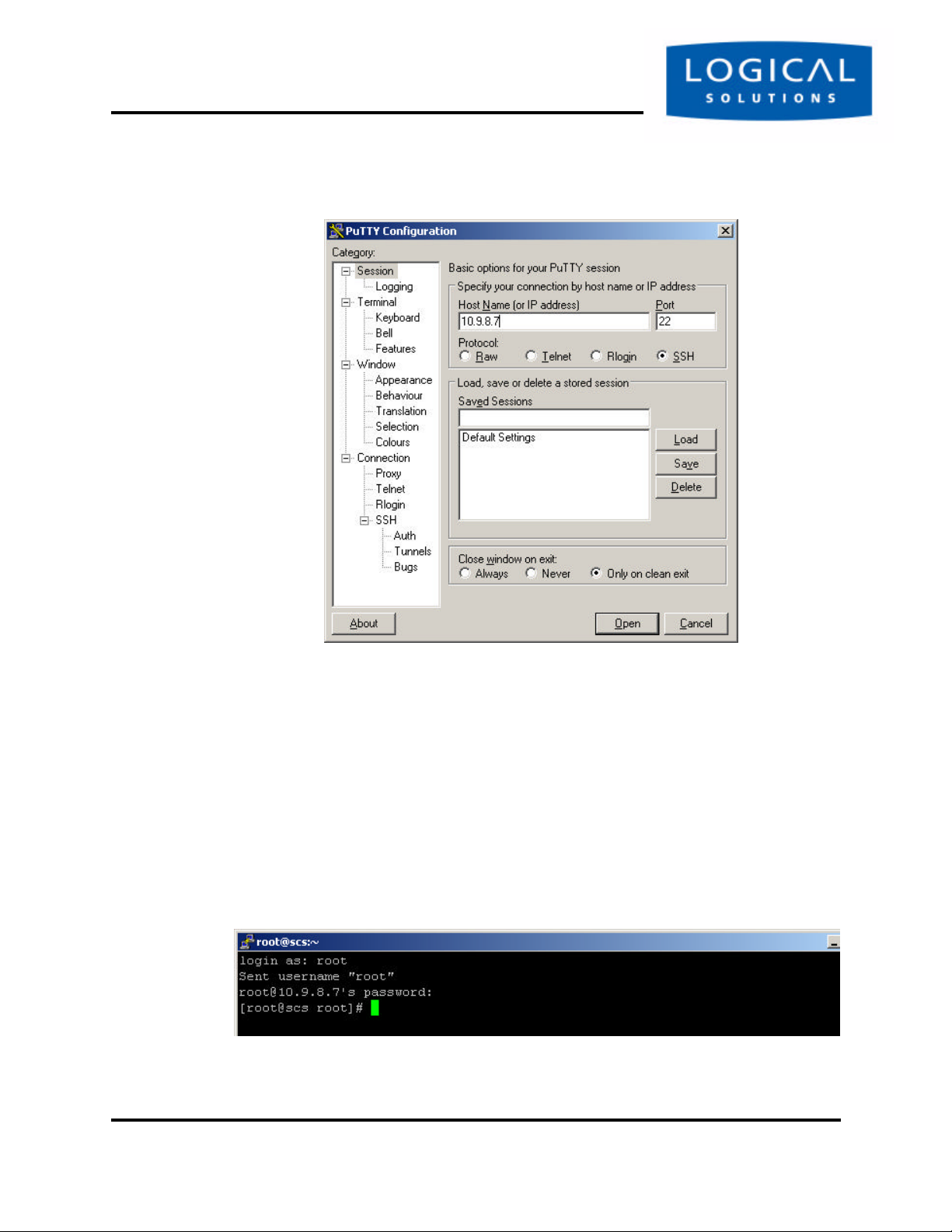
If using PuTTY (shown below), set the Session window IP address to 10.9.8.7, and
select the ssh radio button, and press ‘Open’.
tel (203) 647-8700 Page 31 Product Manual - MAN-000001C
Page 32
Initial Configuration
Figure 4.2 PuTTY Configuration Screen
The first time you connect using ssh, you will get a warning about the ssh authentication keys. Accept the newly-generated keys by choosing ‘yes’.
5. Login to the SCS
When connected to the SCS, the ‘login as:’ prompt will appear. You want to
log in as root . Press Enter to continue.
The ‘password:’ prompt comes up next. Enter root (the default root pass-
word) and press Enter.
You should at the SCS’s root command prompt after pressing the Enter key. In
our case, we connected using PuTTY to ssh into 10.9.8.7:
Figure 4.3 Terminal screen, showing a typical root login to SCS
SCS160 / SCS320 / SCS480 Page 32 www.thinklogical.com
SCS160R / SCS320R
Page 33

Front Panel Network SetupSECURE CO NSO LE S ERVERS
When successfully logged in, you will see the command prompt ending with # followed by your cursor.
You should change your SCS’s network address as one of the first changes you
make. See Section 7.2, Change Network Address, on page 53.
4.4 Front Panel Network Setup
If you changed the Network settings via netconfig, you can skip this section.
By default, the Front Panel Display and buttons can be used to set the basic network parameters. There is one ‘ENTER’ button and four arrow buttons (Left, Right,
Up and Down). The front panel can change the IP Address, Subnet Mask, and Gateway settings. By default, the front panel will show the Hostname and the Date/Time.
Figure 4.4 Default Normal Front Panel Display (Hostname and Date/Time)
scs.localdomainname
Tue Mar 18 15:53:03 2003
4.4.1 Front Panel Edit Mode
By default, the Front Panel Display’s Edit mode is enabled. The View Mode is
similar to Edit mode except that the front panel cannot be used to change the settings.
This is described in Section 7.7, Front Panel Display Options, on page 57 of this manual.
Note
The Front Panel Edit Mode can be disabled, if required. See Section
7.7, Front Panel Display Options, beginning on page 57.
With Edit mode enabled, use the arrow buttons on the front panel to access the
front panel edit subroutine and change the default network settings (showing the IP
address, Netmask, and Gateway) for your SCS system. The front panel controls are
self-prompting for the appropriate entries.
Figure 4.5 SCS Front Panel Display, showing first LCD Mode display
Press Enter to
Program Network Settings
tel (203) 647-8700 Page 33 Product Manual - MAN-000001C
Page 34

Initial Configuration
Note
Use the ENTER button to ‘continue’ or to ‘accept current setting’,
whichever is appropriate at that time.
Your front-panel entries must be no longer than 30 seconds apart, or the front
panel entry program will time out and discard any of your entries. An asterisk to the
far right indicates there is a parameter that has changed from the currently-stored
value. Your entries will be accepted and held; then, as you are exiting this programming
mode, you are given the opportunity to Save or Cancel your new changes. If you do
not Save your settings at this time, your new changes will be discarded.
Note
Front panel changes are not written to the Compact Flash memory
until the sysadmin uses the command-line ‘save’ command. Therefore, do NOT turn the system power off or these changes will be lost.
4.4.1.1 Start Front Panel Edit Mode
To start the Edit mode, press the UP or DOWN Arrow button on the front panel.
The display will change from the default Domain Name / Date & Time to the Edit
Mode. This mode will time out after 30 seconds, and revert to the normal display.
Figure 4.6 SCS Front Panel Display, showing first Edit Mode display
Press Enter to
Program Network Settings
You can scroll through the Edit functions (plus the normal display) that are available by pressing the UP or DOWN arrows:
• Program Network Settings
• View SCS Settings
Note
If you do not press any buttons, the display will revert to the normal
display in approximately 30 seconds, and no changes will be made.
Stop scrolling when you reach the Program Network Settings display.
SCS160 / SCS320 / SCS480 Page 34 www.thinklogical.com
SCS160R / SCS320R
Page 35

Front Panel Network SetupSECURE CO NSO LE S ERVERS
4.4.1.2 Program Network
When you select the Program Network Settings mode, you step through the
parameter entry for Network IP Address, Net Mask and Gateway, and Exit to the previous menu. The Up and Down arrows are used to scroll through the available options.
Network IP Address
Figure 4.2 SCS Front Panel Display, for Network Programming mode
Press Enter to
Program Network Settings
Press the ENTER button to continue.
Figure 4.3 SCS Front Panel Display, showing the current IP Address
IP Address
010.009.008.007
The current IP Address will be displayed, shown with leading zeroes. The factory
default is 10.9.8.7. If you do nothing, the display will revert to the previous display after
30 seconds, and no changes will be made.
Let’s change the IP Address. Press the ENTER button to continue.
Figure 4.4 SCS Front Panel Display, showing Edit IP Address
Edit IP Address
010.009.008.007
A cursor appears under the first character of the existing address. Press the Left or
Right arrow button to move the cursor to the first digit to be changed. To change a
digit, use the Up or Down arrows to change the number.
Note
Ignore any leading 0’s in the display entry. The SCS will adjust for
them and will not store the leading zeroes when saving the data.
tel (203) 647-8700 Page 35 Product Manual - MAN-000001C
Page 36
Initial Configuration
As soon as you change a digit, an asterisk (*) will appear to the right on the top line,
indicating that a parameter has changed.
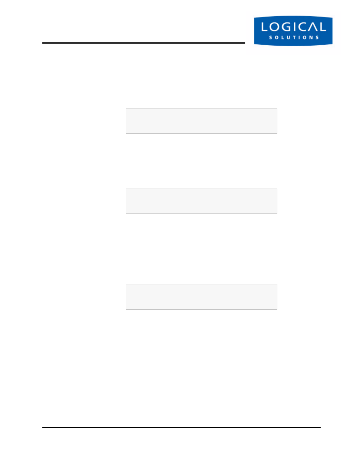
Figure 4.5 SCS Front Panel Display, Asterisk indicating a change
Edit IP Address
*
192.168.075.239
When you have the complete parameter value as it should be, press the ENTER
button to complete the entry.
The display will show the following:
Figure 4.6 SCS Front Panel Display, after editing the IP Address
IP Address
192.168.075.239
Your new value will be stored when you are finished setting all the Network parameters.
Net Mask
Press the Down Arrow once to advance to the Net Mask parameter.
Figure 4.7 SCS Front Panel Display, showing the current Net Mask
Net Mask
255.000.000.000
Press the ENTER button to change the Net Mask parameter. The current Net
Mask setting will be displayed, with a cursor under the first digit. The factory default is
255.0.0.0.
Press the Left or Right arrow button to move the cursor to the first digit to be
changed. To change a digit, use the Up or Down arrows to change the number.
SCS160 / SCS320 / SCS480 Page 36 www.thinklogical.com
SCS160R / SCS320R
Page 37

Front Panel Network SetupSECURE CO NSO LE S ERVERS
Figure 4.8 SCS Front Panel Display, editing the Net Mask setting
Edit Net Mask
*
255.200.000.000
As soon as you change a digit, an asterisk (*) will appear to the right on the top line,
indicating that a parameter has changed. Change the Net Mask as desired.
Note
Ignore any leading 0’s in the display entry. The SCS will adjust for
them and will not store the leading zeroes when saving the data.
When you have the complete parameter value as it should be, press the 'ENTER'
button to complete the entry. The display will show the following:
Figure 4.9 SCS Front Panel Display, showing the new Net Mask display
Net Mask
255.255.000.000
Your new value will be stored when you are finished setting all the Network parameters.
Gateway
Now, enter your Gateway parameter information. Press the Down Arrow once to
continue.
Figure 4.10 SCS Front Panel Display, showing the current Gateway setting
Gateway
010.001.002.003
Press the ENTER button to edit the Gateway parameter. The current Gateway setting will be displayed, with a cursor under the first digit.
tel (203) 647-8700 Page 37 Product Manual - MAN-000001C
Page 38
Initial Configuration
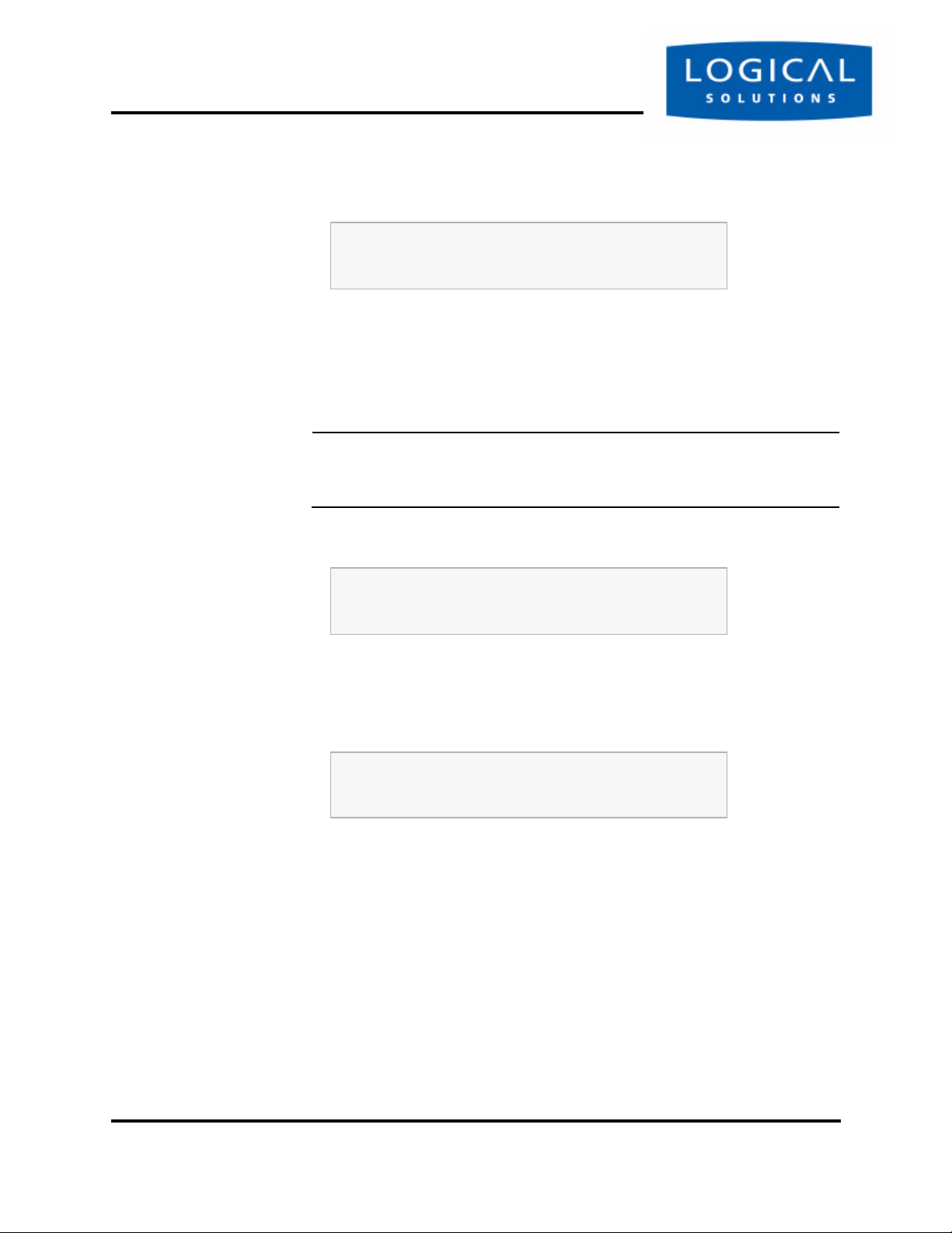
Figure 4.11 SCS Front Panel Display, Edit the Gateway setting
Press the Left or Right arrow button to move the cursor to the first digit to be
changed. To change a digit, use the Up or Down arrows to change the number. As
soon as you change a digit, an asterisk (*) will appear to the right on the top line, indicating that a parameter has changed.
Note
Ignore any leading 0’s in the display entry. The SCS will adjust for
them and will not store the leading zeroes when saving the data.
Edit Gateway
010.001.002.003
Figure 4.12 SCS Front Panel Display, editing the Gateway setting
Edit Gateway
192.168.102.001
When you have the complete parameter value as it should be, press the 'ENTER'
button to complete the entry. The display will show the following:
Figure 4.13 SCS Front Panel Display, showing new Gateway setting
Gateway
192.168.102.001
Your new value will be stored when you are finished setting all the Network parameters.
Exit to Main Menu
You are now prompted to Exit to the Main Menu. Press Enter to continue.
SCS160 / SCS320 / SCS480 Page 38 www.thinklogical.com
SCS160R / SCS320R
Page 39

Front Panel Network SetupSECURE CO NSO LE S ERVERS
Figure 4.14 SCS Front Panel Display, exiting the LCD Mode
Exit to Main Menu
You are given the choice to Save your changes or to Cancel them.
Figure 4.15 SCS Front Panel Display, Save or Cancel Changes
Enter = Save
Cancel = UP
Press 'ENTER' to save your network changed, or press the Up Arrow to discard
them.When you are done with your network settings, and have made changes, the system must restart the network daemon. Progress of this process will be displayed on the
front panel display, and you will see a normal display when the network is restored.
Figure 4.16 SCS Front Panel Display - Saving and Restarting
Saving and Restarting
Network Services
When the system is done restarting the network services, the display will show:
Figure 4.17 Returned to normal SCS Front Panel Display
Save / Reset Complete
Any Key to Continue
To permanently save your new Network settings in the system, you must use the
save command (described later) to write the values to the Compact Flash memory.
Note that if your system loses power before you use the command-line ‘save’ command, your front-panel-entered network parameters changes will be lost.
tel (203) 647-8700 Page 39 Product Manual - MAN-000001C
Page 40

Initial Configuration
For Your Notes
SCS160 / SCS320 / SCS480 Page 40 www.thinklogical.com
SCS160R / SCS320R
Page 41

SCS Systems are Linux-basedSECURE CO NSO LE S ERVERS
5 System Administration
5.1 SCS Systems are Linux-based
The Logical Solutions Secure Console Server products use the GNU/Linux operating system.
5.1.1 Linux General Public License
The GNU/Linux source code used in this product has been distributed under a
General Public License (GPL) from the Free Software Foundation. You may read
about the GNU GPL by reviewing the text version of the GPL, which can be found
at http://www.gnu.org/licenses/gpl.txt.
You will find additional GNU license information online
at http://www.gnu.org/licenses/licenses.html#GPL.
Please contact Logical Solutions Product Support, should you need to obtain a
copy of this source code.
5.1.2 Understanding Linux
Each SCS system is a “Linux box”, meaning you will use Linux commands to
administer it. We must assume a certain level of Linux understanding for our audience.
If you do not know your way around Linux, you may have some difficulties and might
want to get some Linux help. This document is not meant to teach you all about Linux
or the other applications and features available since this system is running Linux.
Those that use this type of system and know Linux should have no trouble configuring
the SCS.
tel (203) 647-8700 Page 41 Product Manual - MAN-000001C
Page 42

System Administration
5.1.3 SCS System Architecture
The SCS software design uses both RAM (volatile) and Compact Flash (non-volatile) memory. Any system changes are maintained in RAM until they are written to the
Compact Flash memory. A read-only memory system is used since Compact Flash
memory devices have a limited number of read-write cycles.
After making administrative changes to the system, the root user must run the
save command to write the changes to the non-volatile memory. If the data changes
are not saved, the parameter changes will be lost in the event of a power failure.
5.2 Initial Sysadmin Access
When the SCS is first powered up, you may want it to be configured to operate
with your network. You will use ssh to access the SCS.
The SCS product uses familiar Linux commands to administer the system. This
manual will list those Linux commands that are important for the SCS sysadmin to
know; other Linux / UNIX commands are discussed in a myriad of Linux reference
and training manuals.
5.2.1 Connect using a Terminal
Connect the SCS’s Console port to your terminal, or to a computer using a terminal
emulation program. When you successfully connect with the SCS, your terminal will
show the header and login prompt:
Figure 5.1 SCS login display (default)
Logical Solutions Inc Secure Console Server
Kernel xxxxxxxxxxxx on an i486
scs.localdomain login:
Later, after you change your SCS’s Hostname, your new hostname information will
be shown in your login line (in place of scs.localdomain, above).
SCS160 / SCS320 / SCS480 Page 42 www.thinklogical.com
SCS160R / SCS320R
Page 43

Initial Sysadmin AccessSECURE CO NSO LE S ERVERS
5.2.2 Log In as root
At the command prompt, type root to access the SCS as the root user. The
default password is root.
Note
The root user should change the default root password (use the
passwd command) as soon as possible to prevent undesired SCS
system access.
You will see the short Hostname (e.g., “scs”) in the root login (#) prompt.
Figure 5.2 SCS login display, showing root user logged in
Logical Solutions Inc Secure Console Server
Kernel xxxx
scs.localdomain login: root
Password:
[root@scs root]#
5.2.3 Enter Commands
The system administrator enters Linux commands using the command-line interface. Unless otherwise shown, commands are all lower-case and may have modifiers.
SCS commands are discussed in Section 6, Commands, beginning on page 47.
5.2.4 Log Out
To log out from a session, use the command logout. If logging out from a network session, the Console Server will disconnect the ssh session.
tel (203) 647-8700 Page 43 Product Manual - MAN-000001C
Page 44

System Administration
5.3 Default Services
The following Services are enabled by default:
• network
• ssh
• syslog
• cron
You may add other features and services, depending on your application. When
you first log into the system, you will get a reminder message for configuration:
Figure 5.3 SCS login advice (displayed on-screen when you first log in)
To customize the SCS configuration for your location,
we suggest you do the following:
* CHANGE THE ROOT PASSWORD!!!
* reconfigure the network (netconfig)
* set the timezone, if not in the Eastern U.S. (timeconfig)
* add users (adduser)
* edit the ntp.conf file and then enable the ntpd service
For extra security:
* edit the sshd_config file to not allow root logins
* when all settings are changed, reboot the system to save any
changes
5.3.1 Configure the Services
To configure the existing features, use the following commands:
For the Network parameters, use netconfig
To change the host and domain name, use changehostname
For the Date/Time, use timeconfig
For the authentication protocols, use authconfig
SCS160 / SCS320 / SCS480 Page 44 www.thinklogical.com
SCS160R / SCS320R
Page 45

Default ServicesSECURE CO NSO LE S ERVERS
5.3.1.1 Configure the Services
When you first install the SCS system, you should configure the default services for
your needs. This addresses the network, the date/time, authorizations, and the system
hostname. The feature commands described below are discussed in Section 7, System
Administration, beginning on page 53.
In order to properly configure the basic services, you must:
1. make all of the changes to the commands (netconfig, changehostname,
timeconfig, authconfig).
2. run save
3. run service network restart to restart the system clock
4. The next time that you ssh in, you will need to make a new ssh connection.
tel (203) 647-8700 Page 45 Product Manual - MAN-000001C
Page 46

System Administration
For Your Notes
SCS160 / SCS320 / SCS480 Page 46 www.thinklogical.com
SCS160R / SCS320R
Page 47

6 Commands
A summary of special SCS Commands
6.1 System Commands
System CommandsSECURE CO NSO LE S ERVERS
The SCS products use Linux command formats, and man pages are available and
online for all system commands. The root user can access the following commands to
configure the special features of the SCS:
COMMAND PURPOSE CH.
adduser
deluser
editbrk
editesc
edituser
lsp
lsc
save
stty
versions
Add a User (creates a new user account) 8
Delete a User account 8
Edit the 'break' sequence 8
Edit interactive mode 'escape' sequence 8
Edit user settings for existing User accounts 8
list port names
list active connections
Commit your programming changes to non-volatile memory 6
Configure Port parameters (see Linux commands)
Show version information
The commands are discussed in the Chapter numbers noted.
tel (203) 647-8700 Page 47 Product Manual - MAN-000001C
Page 48

Commands
power is applied and the system remains in a normal operating condition. To permanently store your parameters, the system has a save command. In order to prevent
the inadvertent loss of your precious data due to an inadvertent power failure, the root
user must use the save command to write the data changes to the non-volatile Com-
pact Flash memory card. This will ensure your data is maintained as desired.
6.2 save Command
The SCS systems will maintain your settings in RAM memory as long as system
The save command does not store buffered port data, which is held in RAM.
Note
The root user should run save any time that the system configuration
has been changed. This includes user password changes and any
command-line system administration changes
The save command is automatically run when you have executed the reboot or
the poweroff commands.
6.3 reboot
During the course of administering the SCS, you may have to reboot the system to
enable certain changes. For example, certain network settings require the service
network restart, which is accomplished during a reboot.
reboot may be manually run at any time, if required. The save command is auto-
run as a part of the reboot command. Reboot occurs immediately after your data has
been saved. After the reboot has properly run the underlying commands, the system
will ‘reset’ and then begin the start up process, as if you had just turned the power on.
Note
No ‘break’ commands will be sent on the serial Ports during a SCS
system reboot. Your servers will not be adversely affected.
The Logical Solutions SCS systems are “break-safe”, meaning that they will not
send a ‘break’ command (unless user initiated) or other data on the serial ports connected to your servers. A ‘break’ might cause problems with your server.
A reboot takes a short period of time, a minute or so, to complete.
SCS160 / SCS320 / SCS480 Page 48 www.thinklogical.com
SCS160R / SCS320R
Page 49

poweroffSECURE CO NSO LE S ERVERS
6.4 poweroff
If you want to turn the system power off (e.g., to move the chassis, etc.) you must
first run the poweroff command before turning the power switch off.
Note
No ‘break’ commands will be sent on the serial Ports during a SCS
system poweroff cycle. Your servers will not be adversely affected.
poweroff may be manually run at any time, if required. The save command is
auto-run as part of the poweroff command. Once you have entered the poweroff
command, the operating system will properly shut down and the SCS will cease operating (almost immediately), and the front panel display will show “OK to Power
Off ” when it has completed the underlying commands. You may then safely turn the
power switch off.
The only way to recover from a poweroff command is to turn the system power
off and then turn the power back on.
6.5 Other Linux Commands
The following Linux commands, among others, will be used with the SCS systems.
logout
Use logout to quit your session with the system.
man
Use man <command name> to search for a help file (online manual pages) or
descriptive information for that Linux / UNIX command.
passwd
The default root password should be changed by the root user, as soon as possible
to prevent access by anyone other than authorized personnel. To change the default
root password, type passwd (all lower case) at the root login prompt.
scp
Use scp for secure copy, using ssh, between two hosts. The process is encrypted
and inherently secure.
tel (203) 647-8700 Page 49 Product Manual - MAN-000001C
Page 50

Commands
sftp
process is similar to ftp except that it is encrypted for security.
ssh
files or data between the systems. With the SCS, the Secure Console Server is a client
device, and will be connected to an ssh host elsewhere. The security keys for ssh may
need to be generated using ssh-keygen, depending on your application of ssh.
Refer to the man pages for scp for a description and any command options.
Use sftp for a secure file transfer transaction using ssh, between two servers. This
Refer to the man pages for sftp for a description and any command options.
The SCS systems use ssh to establish secure connections over your network.
The configuration file for ssh is /etc/ssh/sshd_config.
You use ssh to establish a secure connection between two hosts, or to transfer
Refer to the man pages for ssh for a description and any command options.
ssh-keygen
Use ssh-keygen to create keys for users so passwords don’t have to be used for
ssh login. You can generate the security keys for your client system (in this case, the
SCS is the client) to interact with an ssh host elsewhere. After the keys have been generated, the user can establish a secure shell connection using ssh over a network.
Refer to the man pages for ssh for a description and any command options.
stty
Use stty to change the configuration for each Port. The system provides a
default configuration for the system Ports (ttyB1 through ttyB48), and for the Con-
sole Port (ttyS0).
Note
Port changes made using stty are temporary (not written to memory). In order to keep any changes, you must edit the configuration file
in /etc/rc.d/rc.serial .
The Ports are identified as /dev/ttyB1 through /dev/ttyB48 for ports 1
through 48, respectively, and /dev/ttyS0 for the Console Port.
SCS160 / SCS320 / SCS480 Page 50 www.thinklogical.com
SCS160R / SCS320R
Page 51

Change Logging LevelSECURE CO NSO LE S ERVERS
Note
For example, to administer Port 7 you would edit the file rc.serial
and would use stty -F /dev/ttyB7.
Refer to the man pages for stty for a description and any command options.
versions
Use versions to see a listing of the release versions of the LSI files in the SCS.
6.6 Change Logging Level
The sysadmin may wish to change the logging level of syslog.
1. Login as root
2. Edit the file /etc/syslog.conf (vi /etc/syslog.conf)
3. Restart the system logger by entering: service syslog restart
4. Run save.
tel (203) 647-8700 Page 51 Product Manual - MAN-000001C
Page 52

Commands
For Your Notes
SCS160 / SCS320 / SCS480 Page 52 www.thinklogical.com
SCS160R / SCS320R
Page 53

7 System Administration
This section outlines the administration functions and commands,
accessed using your Network or the Console port.
SecuritySECURE CO NSO LE S ERVERS
7.1 Security
The Logical Solutions Secure Console Servers use ssh to provide encryption for a
secure network connection. There is only one level of system administration access in
the SCS, and that is at the root level.
Caution
Anyone with the root password has the ability to access all SCS features and functions. Your root password should be carefully guarded.
Users do not have the ability to interact with the system-level features. Users that
are granted permission to interact with a Port can access the Buffers and may also clear
the buffered data.
7.2 Change Network Address
You may use the Front Panel setup (see Section 4.4, Front Panel Network Setup, begin-
ning on page 33) to configure the SCS’s IP address. This will temporarily change the
IP address to allow you to connect to the SCS. Front panel changes are temporary in
that there is no way to write the new parameters to non-volatile memory using just the
front panel keys.
You must run netconfig once you have accessed the SCS to change all of the
network parameter options, and then save the parameters to non-volatile memory.
tel (203) 647-8700 Page 53 Product Manual - MAN-000001C
Page 54

System Administration
7.2.1 Run netconfig
After you establish a connection to the SCS using your network, you may want to
change the IP address setting of the SCS to the desired address on your network, using
netconfig.
The netconfig script is a self-prompting program to set up your system’s net-
work information. It supports DHCP/BOOTP setup, or static addressing.
Use the space bar to select / deselect a value (e.g., DHCP). Use the arrow keys
to move up and down between the entry fields.
Note
Use of a static IP address is recommended with the SCS.
You will need the following information before running netconfig:
• Using BOOTP/DHCP (yes/no)? If No, you need the following:
• IP Address
• Net Mask
• Default Gateway
• Primary Nameserver
You can add the secondary and tertiary nameservers (if required) by editing your
resolv.conf file at a later time. After entering the requested information, you are
returned to the root prompt.
SCS160 / SCS320 / SCS480 Page 54 www.thinklogical.com
SCS160R / SCS320R
Page 55
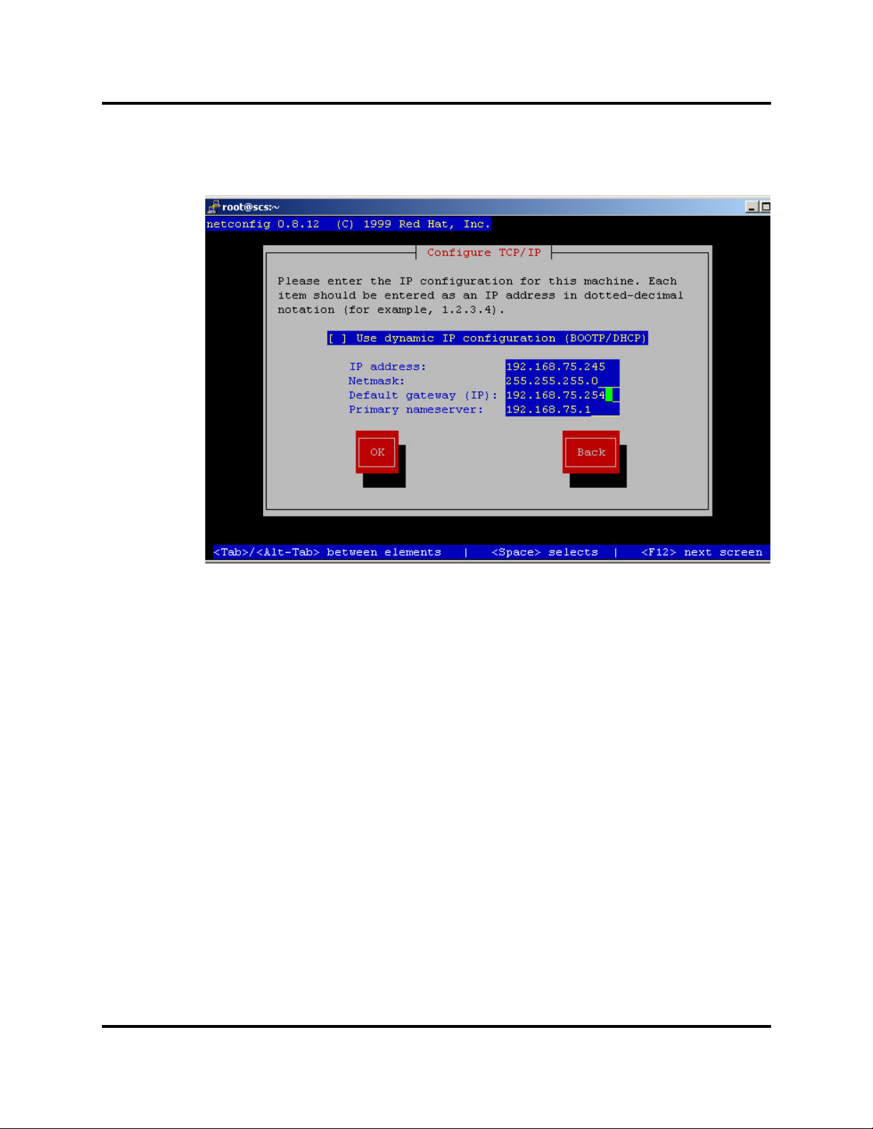
Figure 7.1 Example of netconfig fill-in fields
Change Network AddressSECURE CO NSO LE S ERVERS
When you have filled in the fields, arrow down to the OK button and press Enter
to accept your entries.
7.2.2 More Than One Nameserver
The netconfig command allows the user to set up one nameserver’s IP address.
It is possible to have multiple nameservers, which must be done outside of the
netconfig routine. The nameserver data is in the file /etc/resolv.conf.
If you want to have more than one nameserver, you must edit the file
/etc/resolv.conf . For more information, refer to the MAN page for
resolv.conf.
In this file, you will find the IP address you entered with netconfig. You can
add more lines (maximum of 3 nameservers is allowed) to this file with the address of
additional nameservers.
The format of a line is: nameserver <IP address>.
tel (203) 647-8700 Page 55 Product Manual - MAN-000001C
Page 56

System Administration
7.3 Change Hostname
The SCS includes a command changehostname which allows the root user to
change the long hostname of the SCS unit.
1. Log in as root.
2. Type changehostname. The current hostname is displayed, and you are
prompted to choose y/n to proceed.
3. If you select y to change, you are prompted to enter the new hostname.
Note
If you make a mistake in your entry, simply continue (do not attempt
to edit); you can reject your bad entry and re-enter the value properly.
4. Enter your new hostname value. Accept it (y) to accept the new value.
Remember to run save when done to keep your new values.
7.4 Time Configuration
Use the command timeconfig to set up the date/time and time coordinates.
This is a self-prompting utility. Remember to run save when done to keep your values.
Note
If changing the Time Zone (during timeconfig changes) it is neces-
sary to restart the lcd display service in order for the front panel display to update. This is done by using the command service lcd
restart after completing the timeconfig options.
7.5 Change NIC Speed
You can change the NIC interface configuration from auto-sensing to be fixed, for
full or half duplex, and 10Mbit or 100Mbit. The following file information is found in
the file /etc/module.conf, but with some additional instructions added to as to
how to set the NIC speed.
SCS160 / SCS320 / SCS480 Page 56 www.thinklogical.com
SCS160R / SCS320R
Page 57

Configure AuthenticationsSECURE CO NSO LE S ERVERS
This file already has the various commands in place, but they are commented out.
Edit your /etc/module.conf as appropriate. Remove the '#' from one of the four
options lines above, and then reload the NIC driver.
alias eth0 eepro100
alias char-major-72 exser
alias char-major-4 off
options -k exser
##
## options to control NIC speed and mode
## remove the leading '#' from ONE of the options lines below
##
### 100Mbit half-duplex
#options eepro100 options=0x20
### 100Mbit full-duplex
#options eepro100 options=0x30
### 10Mbit half-duplex
#options eepro100 options=0x40
### 10Mbit half-duplex
#options eepro100 options=0x50
The SCS system should be power cycled (using poweroff, not reboot). The poweroff is done to convince whatever switch the NIC is connected to, that it is indeed off.
7.6 Configure Authentications
Use authconfig to set up the authentication protocols (e.g., ssh). Refer to the
man page nscd for configuration options.
The first checkbox, cache information , will start the nscd daemon if
selected. This is not required for normal operation and need not be selected.
Other aspects of the authentication options in authconfig are self-prompting
for parameters for NIS, LDAP and/or Hesiod.
Remember to run save when done to keep your new values.
7.7 Front Panel Display Options
The front panel Display is a two line, 24 character backlit LCD. It shows system
messages during certain system events (e.g., network restart, poweroff), but most of
the time is idle and shows a ‘normal’ display.
The LCD Display offers several ‘normal’ display features. The default display
shows the Hostname on the top line, and the Date/Time on the lower line. The display
can be customized, if desired, to show other information in the top line or the bottom
line, or both. This might be useful to provide method of labeling each SCS in a rack
with multiple units installed. The normal display can also be turned off.
tel (203) 647-8700 Page 57 Product Manual - MAN-000001C
Page 58

System Administration
Figure 7.2 Default ‘Normal’ Front Panel Display,
scs.localdomainname
Tue Mar 18 15:53:03 2003
The front panel will display system messages (e.g., during reboot or save events)
but will return to the ‘normal’ display after these events are done.
Note
The Edit Mode can be disabled, and the front panel display’s normal
display can also be changed.
The default setting allows the editing of the IP address information using the front
panel buttons. This can be disabled to prevent unauthorized changes.
7.7.1 Display Mode Parameters
The various LCD Display modes are controlled by the entries maintained in
the /etc/sysconfig/lsi directory for the following files:
LCD_LINE_1=
LCD_LINE_2=
LCD_DISPLAY_SETTING=
• LCD_LINE_1= and LCD_LINE_2= allows text entry of up to 24 characters to be displayed.
• LCD_DISPLAY_SETTING= can be set to EDIT (default), VIEW, or OFF.
7.7.1.1 Edit
The Edit mode (LCD_DISPLAY=EDIT) allows the front panel display to normally
show the current Display information, and allows anyone to use the front panel display
to change the network parameters (IP Address, Net Mask, and Gateway).
7.7.1.2 View
The View mode (LCD_DISPLAY=VIEW) allows the front panel display to show
the current information, but disables the editing using the front panel buttons. This
prohibits unauthorized changes to your network settings from the front panel.
SCS160 / SCS320 / SCS480 Page 58 www.thinklogical.com
SCS160R / SCS320R
Page 59

Network Time ServiceSECURE CO NSO LE S ERVERS
7.7.1.3 LINE_1
LINE_1= info allows the Customer to show any data they choose on the upper
line of the display. The root user enters a left-justified text line, up to 24 characters,
which will be displayed. The upper line of the display is otherwise the SCS’s Hostname.
Figure 7.3 LINE_1 Changed in SCS Front Panel Display,
24 characters for Line 1
Tue Mar 18 15:53:03 2003
7.7.1.4 LINE_2
LINE_2= info allows the Customer to show any data they choose on the lower line
of the display. The root user enters a left-justified text line, up to 24 characters, which
will be displayed. The lower line of the display is normally a clock/date display.
Figure 7.4 LINE_2 Changed in SCS Front Panel Display,
scs.localdomain
SCS320 SerNum 1234567890
7.7.1.5 Display OFF
The Off mode (LCD_DISPLAY=OFF) disables the front panel LCD display during
normal mode. The backlighting will remain on, but the display is blank. The display
will still show certain system events to the front panel display.
7.8 Network Time Service
Network Time Service is supported. To use the network time service, you must
edit two files (/etc/ntp.conf and /etc/ntp/step-tickers) and start the
ntpd service.
Note
More information is available at www.ntp.org
tel (203) 647-8700 Page 59 Product Manual - MAN-000001C
Page 60

System Administration
7.8.1 Configure NTP
The file /etc/ntp.conf has many options. We want to define the time servers
to use. You need the hostname (or IP address) of the time servers you wish to access.
Using your editor, edit the file and add the line:
server <my time server name or IP address>
to the end of the file.
For example, let's use the name ts1.mydomain . Your entry is
server ts1.mydomain
You need the hostname (or IP address) of the time servers you wish to access.
You should also add the server names to the file /etc/ntp/step-tickers.
This file just needs the name of the time servers (the word 'server' as used in the
file /etc/ntp.conf is not needed)
7.8.2 Start the NTP Service
To start the NTP service manually:
service ntpd start
To cause NTP to start automatically on startup:
chkconfig ntpd on
SCS160 / SCS320 / SCS480 Page 60 www.thinklogical.com
SCS160R / SCS320R
Page 61

NIS and User Port PermissionsSECURE CO NSO LE S ERVERS
7.9 NIS and User Port Permissions
The SCS can use NIS to control user access to the Ports in addition to controlling
user access to the SCS itself. This is an extension to the normal NIS capabilities. Some
of the NIS files must be installed on your NIS server. The user must create/modify
their NIS database to include records containing user port permissions.
Note
Source documents, including this information, is stored on the hard
drive of the SCS system.
NIS information is located in /usr/doc/nis.
7.9.1 User Port Control
The SCS can use NIS to control which user can access a port on the SCS. To utilize
this feature, a database must be created on the NIS server. The following files are
needed to set up the port access database:
lsi_port_access Port Access Permission Definition file
lsi_port_user Port Access User Definition file
lsi_port_awk Port Access AWK file (required for the
Make file)
Makefilenis.portAccess Make file used to build the LSI database
7.9.2 Changing Serial Port settings
Use 'stty' to change things like the port name, baud rate, hard/soft flow control.
Note that these changes are temporary, and will but lost on the next reboot. To make
the changes permanent, the file /etc/rc.d/rc.serial must be edited. This file
contains a list of stty commands (one for each port).
tel (203) 647-8700 Page 61 Product Manual - MAN-000001C
Page 62

System Administration
7.9.3 NIS Port Access
The file lsi_port_access contains the port permissions for connect, monitor
and clear. It is referenced by a group; you may define any number of groups you need.
The following example will illustrate how the group file is constructed.
group name : console server name : connect perm : monitor perm : clear perm
where:
console server name is the SCS’s hostname
For example:
pbxgrp : tvscs320 : 1,2-6,13 : 5-9 : 1,7
itgrp : tvscs160 : 8-16 : 7 : 1,3,5,7-11
The above example shows two groups (pbxgrp and itgrp) that are allowed to
access port on a secure console server.
group name is the name of the user’s group
connect perm port that a group can connect with
monitor perm ports that a group can monitor
clear perm ports that a group are allowed to clear
The first group, pbxgrp, can access an SCS with the hostname of tvscs320. The
group can connect to ports 1,2,3,4,5,6 and 13. It can monitor ports 5,6,7,8 and 9. This
group is allowed to clear ports 1,2,3,4,5,6 and 7.
The second group, itgrp, can access the SCS with a hostname of tvscs160. This
group can connect to ports 8,9,10,11,12,13,14, 15 and 16. It can monitor port 7, and
can clear ports 1,3,5,7,8,9,10 and 11.
# LSI Port Access Permission file...
# Port Access Permission for the user defined group name(s) are defined below
# Permissions can be any or all of the forms:
# - decimal value
# - decimal range using a dash (-) as the range indicator
# - a comma (,) is used to separate digits and/or ranges
# - a colon (:) is used as the field separator.
#
# group name : console server name : connect perm : monitor perm : clear perm
user_group1 : scs160_milford : 1-16 : 1-3,5,8,16 : 0
user_group2 : scs320_boston : 1-6 : 12,15 : 3-7
SCS160 / SCS320 / SCS480 Page 62 www.thinklogical.com
SCS160R / SCS320R
Page 63

NIS and User Port PermissionsSECURE CO NSO LE S ERVERS
7.9.4 User Names and Groups
The LSI Port User Definition file (/nis/lsi_port_users) is used to assign a
user to a given Port Access group. This file information is found in /usr/doc/nis.
The following example will illustrate how it is set up.
user name : group name
where
user name a valid SCS user
group name a valid user’s group
Example:
tomv : pbxgrp
billf : itgrp
The above example shows two users, tomv and billf. User tomv is in the group
pbxgrp and billf is in the group itgrp. When user with the lsi_port_access file, it illus-
trates how tomv can log into tvscs320 and be able to connect, monitor and clear the
ports that were set up in the previous example. The same goes for billf.
# LSI Port Access User definition file...
# Port Access user and their respective ‘port access group name is defined
# below.
# Users must be valid system usernames.
# Group names are those defined in the “lsi_port_access” file.
#
# user_name : group_name
lsiuser1 : user_group1
lsiuser2 : user_group1
lsiuser3 : user_group2
lsiuser4 : user_group2
Group Permissions
A user may not get access to a port, depending on their group permissions. Only
members of the scsusers group (group id of 701) may access SCS ports. Only members
of the monitor group (group id of 702) may access SCS monitor ports.
7.9.5 NIS Database file
The lsi_port_awk file is used to create the lsi database file (lsiportdbase)
on the NIS server. It contains the awk code that the Make file needs.
tel (203) 647-8700 Page 63 Product Manual - MAN-000001C
Page 64

System Administration
7.9.6 NIS Make file
The file Makefile.nis.portAccess is used to create the lsi port database.
To build the database, the above files (listed in Section 7.9, NIS and User Port Permis-
sions, on page 61) need to be loaded on the NIS server. The system has been tested on
a linux machine running RedHat 8.0. The files were placed in the /var/yp directory.
After the make file executed, the lsi database file was placed in the NIS host directory.
7.9.7 NIS Configuration File
The NIS configuration file (located at /etc/nsswitch.conf) must be edited
by the user to support your NIS server. To do this:
1. Open the file /etc/nsswitch.conf using your editor.
2. Edit (add or modify) a line to your config file that supports local files for local users,
and if not assigned locally, refers to the NIS database. The line should read:
port_access : files nis
3. Save your updated nsswitch.conf file.
7.10 NFS
NFS information can be obtained from the MAN pages. Refer to the following
man pages: nfs, mount, fstab.
This section is an overview of setup information for an NFS application, as it pertains to the SCS.
7.10.1 Remote NFS Directory
To mount a remote directory onto the SCS, you must start the portmap service
and the nfslock service.
To manually start these services (portmap and nfslock):
service portmap start
service nfslock start
You may have these services start automatically at power on. To do so, enter the
commands:
chkconfig portmap on
chkconfig nfslock on
Determine which local directory name you will use to refer to the remote directory.
The standard name used is /mnt. If you need more than one remote directory
SCS160 / SCS320 / SCS480 Page 64 www.thinklogical.com
SCS160R / SCS320R
Page 65

SNMPSECURE CO NSO LE S ERVERS
mounted, then create the additional directories under the /mnt directory
(e.g., /mnt/dir1, /mnt/dir2, /mnt/dir3...).
To test the mounting, enter the following:
mount -t nfs <remote server name>:<remote directory name>
<local directory name>
Example: mount -t nfs nyc:/usr/local/cvs /mnt/dir2
Note
To have this mount happen at startup, you must edit the
file /etc/fstab. See the man pages above for details.
Here is a sample entry:
nyc:/isr/local/cvs /mnt/dir2 nfs hard,intr
7.11 SNMP
SNMP is supported in the SCS. SNMP is ‘read only’. Refer to the MAN pages for
SNMP for more details.
7.11.1 Start SNMP
SNMP is started with the command service snmpd start
chkconfig snmpd on
7.12 syslog
Using default settings, the SCS will log all warnings and higher events. The SCS
keeps a system log file called /var/log/messages. The level of logging is con-
trolled by the file /etc/syslog.conf.
The SCS products can log the following:
• Notice level events:
• port settings changed
• begin and end interactive mode
• port buffer cleared
• Info level events:
• user settings modified
• Port buffer accessed
tel (203) 647-8700 Page 65 Product Manual - MAN-000001C
Page 66

System Administration
The default file entry is *.notice, with lower level settings (a lower level
generates more messages) in *.info .
7.13 Timeouts
The SCS system supports timeout on the network port. Refer to the man
page for timeout options.
Use the commands timeoutd and timeouts.
SCS160 / SCS320 / SCS480 Page 66 www.thinklogical.com
SCS160R / SCS320R
Page 67

User SetupSECURE CO NSO LE S ERVERS
8 Administering Users
The following commands are used to change settings for Users. You can define as
many Users as you wish, up to the memory capacity of the system. The limiting factor
when it comes to Users is not the number of users but rather the number of simultaneous sessions invoked by any number of users (250 sessions maximum).
8.1 User Setup
Each user account must have a unique name, and each has its own password. Each
User account has the following parameters:
Parameter Constraints
name A unique user name made up of contiguous characters. Cannot
be renamed. This name will be displayed at the command
prompt when a user has logged in.
password Linux password for this user account.
port range or
port group
(used below)
ESCAPE_SEQ Escape sequence. Default is “Esc-A”. Displayed in ASCII (x1bA)
BREAK_SEQ Break sequence. Default is “Esc-B”. Displayed in ASCII (x1bB)
ALLOW_CLEAR Range or group of Ports for which this User account can Clear
ALLOW_CONNECT Range or group of Ports to which this User account can connect
Default is set to access all ports in the SCS chassis (1-16, 1-32
or 1-48). Ports can be assigned individually (1), in a contiguous
range (2-7), in random ports (3,6,9,15) or any combination of the
above (1,4-7,12,15-16) of valid port numbers for that chassis.
the Port Buffers.
ALLOW_MONITOR Range or group of Ports which the User can monitor
tel (203) 647-8700 Page 67 Product Manual - MAN-000001C
Page 68

Administering Users
There are three permissions in the user config files:
ALLOW_CONNECT
User can enter interactive mode (file name is /dev/ttyBnnn). In order to browse
a buffer, a user must have connect permissions on that port.
ALLOW_MONITOR
A user can watch a port (file name is /dev/monitor_portnnn , must be opened
in Read-only mode)
ALLOW_CLEAR
A user can clear a buffer (file name is /proc/port_buffers/nnn)
8.1.1 adduser
SCS Users are identified by a name. The adduser command is used to create a
new user account. The user’s name, password, and port access configurations are set,
along with the Escape and Break command keystrokes. After a user has been added,
this user can log into the system from a network or console port connection.
8.1.2 edituser
The edituser command is used to change the parameters for an existing user.
The user name cannot be edited using edituser; in order to modify a user’s name,
you must generate a new user account and enter the appropriate assignments. You
should then delete the original user account.
8.1.3 deluser
The deluser command is used to delete an existing user account.
Note
The following command modifiers (options) apply to the adduser and
edituser commands.
8.1.4 Other Editing Commands
The following commands may be entered to change the following parameters. The
root user may change the preset values for these parameters, and a User may also use
this command to change the parameter for the Port to which they are connected.
SCS160 / SCS320 / SCS480 Page 68 www.thinklogical.com
SCS160R / SCS320R
Page 69

User SetupSECURE CO NSO LE S ERVERS
8.1.4.1 editbrk <name>
Use editbrk <name> to edit the break sequence for a user. The break
sequence (user key strokes, default is 'ESC - B') is presented in its ASCII form.
8.1.4.2 editesc <name>
Use editesc <name> to edit the escape sequence for a user. The escape
sequence (user key strokes, default is 'ESC - A') is presented in its ASCII form.
tel (203) 647-8700 Page 69 Product Manual - MAN-000001C
Page 70

Administering Users
For Your Notes
SCS160 / SCS320 / SCS480 Page 70 www.thinklogical.com
SCS160R / SCS320R
Page 71

User AccountsSECURE CO NSO LE S ERVERS
9 User Operations
Commands that an End User needs to connect to their Servers through the SCS
9.1 User Accounts
The SCS has two types of user accounts: user, and root.
The SCS supports multiple user accounts, each having a unique combination of
read, write and review privileges to each of the Ports. Each defined user may or may
not have the ability to interact with any of the attached servers, in any possible combination. Each user account is password protected.
9.1.1 SCS Users
SCS users are individuals that must connect with any or all of the attached networking devices, for service, support or access needs. There can be many users
defined, many more than would normally be required. Each user, when connecting to
the system, establishes a session with a selected device by entering the connect com-
mand. There may be up to 250 simultaneous user sessions.
9.1.2 root user
The root user is not like other SCS users. The root user will act as the System
Administrator of the SCS and has full access to the each of the SCS Ports. There is only
one root user for each SCS system.
The root user defines the access rights of all users in the SCS system. The root
user’s access is secured with the root password (default password is root). The root
password should be changed and carefully guarded to prevent undesirable access.
tel (203) 647-8700 Page 71 Product Manual - MAN-000001C
Page 72

User Operations
9.2 Port Identities
Each Port is numbered (1 through 48) and have default names (port1 through
port48, respectively) and may also be given a familiar name by the sysadmin. The
Users interact with the servers connected to the ports by entering a command associated with either the port number or port name.
9.3 What Can A User Do
Summary: use connect <Port number or name> to access a specific server
or network device.
9.3.1 Access via Network
To access a connected server via the SCS network port, the user should use an ssh
client to ssh to the IP address of the SCS.
9.3.2 ssh to a Port
You can ssh directly to a port by logging in and using the following:
ssh user@scs -t -t connect <port number or name>
9.3.3 Access via Console Port
The Console port is normally used by the System Administrator during service
events, however it can be used by any user that has access to the terminal and that has
a password to log into the system and access system Ports.
9.3.4 Interactive Mode
If a user desires to interact directly with an attached server they must enter interactive mode. Use connect <port name or number> to connect to a port
(only applies to ports for which this user is allowed CONNECT access).
The user's terminal will then be directly connected to the server, and will act as if
the terminal was physically connected to the server. The SCS displays the last page of
the port buffer along with a system information message indicating which Port is
selected as the user enters interactive mode.
When a user attempts to connects to a port that is already in use, they will receive
a message Device or Resource busy.
SCS160 / SCS320 / SCS480 Page 72 www.thinklogical.com
SCS160R / SCS320R
Page 73

What Can A User DoSECURE CO NSO LE S ERVERS
To escape from interactive mode, the interactive mode escape sequence must be
used. The interactive mode escape sequence is a series of two to ten characters that
allow the user to leave interactive mode and return to the system prompt. The default
for the interactive mode escape sequence is <ESC> A (escape key, then uppercase
"A"), but the user may change the sequence by using the command editesc.
9.3.5 Break Sequence
The user is not directly connected to the server, but rather is connected through
the SCS, and therefore cannot use their ‘break’ key. While a user is connected to a port
in the interactive mode, the user can send a break signal to the port by entering a command to cause the Break sequence to occur.
The default value for this sequence is 'ESC - B'.
9.3.5.1 editbrk
When no in the interactive mode, a user can enter editbrk to edit or view their
preset break sequence. The break sequence (user key strokes, default is 'ESC - B') is
presented in its ASCII form (x1bB). If the user wishes to keep the existing sequence,
they need only to press <ENTER> to keep the existing setting.
Caution
It is generally best to have the sysadmin change the Break sequence,
as there may have been an equipment change or other issue that a
remote user might not be aware of.
9.3.6 Escape Sequence
A user-defined sequence of keys is used to leave the interactive mode.
The default value for this sequence is 'ESC - A'.
Note
It is best to NOT use combinations of the <CTRL> key and other keys
for the Escape sequence, as these combinations are usually reserved
for sending and receiving special characters through a terminal.
tel (203) 647-8700 Page 73 Product Manual - MAN-000001C
Page 74

User Operations
9.3.6.1 Edit Escape Sequence
The User can edit the Escape command sequence, if necessary. The user only
change the escape sequence if it causes problems with the hardware or software used.
When logged in, a user can enter editesc to edit or view their preset ‘Escape’
sequence. The escape sequence (user key strokes, default is 'ESC - A') is presented
in its ASCII form (x1bA). If the user wishes to keep the existing sequence, they need
only to press <ENTER> to keep the existing setting.
Caution
It is generally best to have the sysadmin change the Escape
sequence, as there may have been an equipment change or other
issue that a remote user might not be aware of.
SCS160 / SCS320 / SCS480 Page 74 www.thinklogical.com
SCS160R / SCS320R
Page 75

10 Regulatory & Safety
Regulatory Information and Contact Information
10.1 Safety Requirements
Safety RequirementsSECURE CO NSO LE S ERVERS
10.1.1 Symbols found on the Product
Markings and labels on the product follow industry-standard conventions. Regulatory markings found on the products comply with requirements.
10.1.2 Product Serial Number
The SCS products have a unique serial number, imprinted on a small silver label
that is placed on the bottom of the chassis. The serial number includes a date code.The
serial number is also found on the original shipping carton.
10.1.3 Connection to the Product
Connections and installation hardware for the product use industry-standard
devices and methods. All wiring connections to the customer equipment is done in a
fashion to minimize proprietary or customized connectors or cabling. Power connections are made with regionally appropriate power cords and approved methods. Rack
mounting equipment is designed for industry-standard 19-inch rack units.
tel (203) 647-8700 Page 75 Product Manual - MAN-000001C
Page 76

Regulatory & Safety
10.2 Regulatory Compliance
The Logical Solutions Inc. SCS products are designed and made in the U.S.A. The
SCS products have been tested by a nationally recognized testing laboratory and found
to be compliant with the following standards (both domestic USA and many international locations).
10.3 North America
These products comply with the following standards:
Safety
• UL60950 : 2000
• CAN/CSA C22.2 No. 60950-00
Electromagnetic Interference
• FCC CFR47, Part 15, Class A
• Industry Canada ICES-003 Issue 2, Revision 1
10.4 European Union
10.4.1 Declaration of Conformity
Manufacturer’s Name & Address
Logical Solutions Inc.
100 Washington Street
Milford, Connecticut 06460 USA
Telephone (203) 647-8700
Product Name
• Model: SCS160 Secure Console Server, SCS1601 Secure Console Server
• Model: SCS320 Secure Console Server, SCS3201 Secure Console Server
• Model SCS480 Secure Console Server, SCS4801 Secure Console Server
These products comply with the requirements of the Low Voltage
Directive 72/23/EEC and the EMC Directive 89/336/EEC.
SCS160 / SCS320 / SCS480 Page 76 www.thinklogical.com
SCS160R / SCS320R
Page 77

European UnionSECURE CO NSO LE S ERVERS
10.4.2 Standards With Which the Products Comply
Safety
• IEC60950:1992+A1, A2, A3, A4, A11
Electromagnetic Emissions
• EN55022: 1994 (IEC/CSPIR22: 1993)
• EN61000-3-2/A14: 2000
• EN61000-3-3: 1994
Electromagnetic Immunity
• EN55024: 1998 Information Technology Equipment-Immunity Characteristics
• EN61000-4-2: 1995 Electro-Static Discharge Test
• EN61000-4-3: 1996 Radiated Immunity Field Test
• EN61000-4-4: 1995 Electrical Fast Transient Test
• EN61000-4-5: 1995 Power Supply Surge Test
• EN61000-4-6: 1996 Conducted Immunity Test
• EN61000-4-8: 1993 Magnetic Field Test
• EN61000-4-11: 1994 Voltage Dips & Interrupts Test
10.4.3 Supplementary Information
The following statements may be appropriate for certain geographical regions and
might not apply to your location.
Note
This equipment has been tested and found to comply with the limits
for a Class A digital device, pursuant to part 15 of the FCC Rules.
These limits are designed to provide reasonable protection against
harmful interference when the equipment is operated in a commercial
environment. This equipment generates, uses and can radiate radio
frequency energy and, if not installed and used in accordance with the
instruction manual, may cause harmful interference to radio communications. Operation of this equipment in a residential area is likely to
cause harmful interference in which case the user will be required to
correct the interference at his own expense.
tel (203) 647-8700 Page 77 Product Manual - MAN-000001C
Page 78

Regulatory & Safety
Note
This Class A digital apparatus complies with Canadian ICES-003 and
has been verified as being compliant within the Class A limits of the
FCC Radio Frequency Device Rules (FCC Title 47, Part 15, Subpart
B CLASS A), measured to CISPR 22: 1993 limits and methods of
measurement of Radio Disturbance Characteristics of Information
Technology Equipment.
This Class A digital apparatus meets all requirements of the Canadian InterferenceCausing Equipment Regulations.
Cet appareil numérique de la classe A respecte toutes les exigencies du Règlement
sur le matérial brouilleur du Canada.
WARNING
This is a Class A product. In a domestic environment this product may cause radio interference, in which case the user may
be required to take adequate measures.
10.5 Australia & New Zealand
This is a Class A product. In a domestic environment this product may cause radio
interference, in which case the user may be required to take adequate measures.
10.6 Lithium Battery
The SCS products have a replaceable long-life Lithium battery for support the system BIOS, which will likely never need field replacement. However, if it must be
replaced, the following caution statement applies:
Caution
RISK OF EXPLOSION IF BATTERY IS REPLACED BY AN INCORRECT TYPE. DISPOSE OF UNUSED BATTERIES ACCORDING TO
THE MANUFACTURER’S INSTRUCTIONS.
SCS160 / SCS320 / SCS480 Page 78 www.thinklogical.com
SCS160R / SCS320R
Page 79

SCS160R / SCS320R Power ModulesSECURE CO NSO LE S ERVERS
10.7 SCS160R / SCS320R Power Modules
The SCS160R and SCS320R systems have hot-swappable AC Power Modules
which can be replaced by a competent technician in the field without interrupting service. Each Module is held in place with a single captive screw.
When servicing the product, it is very important for the user to heed the following
Caution:
Caution
When replacing an AC Power Module in the field, you must first turn
its power switch off, then remove its AC Power Cord, BEFORE you
loosen the screw and pull the module out. When replacing the module, fully insert the module and tighten its screw before replacing its
power cord.
tel (203) 647-8700 Page 79 Product Manual - MAN-000001C
Page 80

Regulatory & Safety
For Your Notes
SCS160 / SCS320 / SCS480 Page 80 www.thinklogical.com
SCS160R / SCS320R
Page 81

Customer SupportSECURE CO NSO LE S ERVERS
11 How to Contact Logical
11.1 Customer Support
Thank You to our Customers for choosing a Logical Solutions product for your
application. We appreciate your business and are interested in helping you successfully
use our products.
Logical is here to help you. To contact Logical Solutions, use the following telephone numbers and internet-based methods.
If you’re not yet a Customer, but are interested in finding a Logical Solution for
your application, we’ll be glad to help you. Our expert Sales staff will help determine
the best solution for your needs, and will help you be certain that you’ve come to a
Logical Solution, too.
Any information we gain about our customers is held in confidence. We do not
share customer names or contact information with other companies.
11.1.1 Website
Check out our website for current product offerings, support information, and
general information about all of the Logical Solutions we offer.
Our internet website offers product information on all current systems, including
technical specification sheets and installation guides (for viewing on-line or for download), product diagrams showing physical connections, and other information you
might need. We are constantly updating our website, so be sure to “refresh” your
browser when visiting the Logical Solutions website to see the most up-to-date information.
Internet: www.thinklogical.com
tel (203) 647-8700 Page 81 Product Manual - MAN-000001C
Page 82

How to Contact Logical
Note
Most online documents are stored as Adobe Acrobat “PDF” files. If
you do not have the Adobe Acrobat Reader needed to view PDF files,
visit www.adobe.com for this free download.
11.1.2 E-mail
Logical Solutions is staffed Monday through Friday from 8:30AM to 5:30PM,
Eastern Time Zone. We will try to respond to your email inquiries promptly, using the
following email addresses for your different needs:
[email protected] -- Information on Logical Solutions and our products
[email protected] -- Sales Department - orders, questions or issues
[email protected] -- Product support, technical issues or questions,
product repairs, requests for Return Authorization, any other issue.
11.1.3 Telephone
Telephone Sales: Contact our expert technically-oriented Sales staff via telephone in Milford, Connecticut, at (203) 647-8700 or if in the continental US, you may
use our toll-free number (800) 291-3211. We’re here Monday through Friday, 8:30AM
to 5:30PM, Eastern Time Zone. Ask for their direct dial phone number when you call!
Telephone Product Support: Contact Product Support via telephone in Milford,
Connecticut, at (203) 647-8700. The support lines are manned Monday through Friday,
9AM to 5PM, Eastern Time Zone.
International Sales: Please contact our US Sales staff in Milford, Connecticut, at
(203) 647-8700. We’re here Monday through Friday, 8:30AM to 5:30PM, Eastern
Time Zone (same as New York City). If leaving a voice message, please provide a ‘best
time to call back’ so we may reach you at your convenience.
We have an automated attendant answering our main telephone switchboard 24
hours a day. You can leave voice messages for individuals at any time. Our Sales Representatives have direct numbers to speed up your next call to us.
11.1.4 Fax
Our company facsimile number is (203) 783-9949. Please indicate the nature of the
fax on your cover sheet, and provide return contact information.
SCS160 / SCS320 / SCS480 Page 82 www.thinklogical.com
SCS160R / SCS320R
Page 83

Product SupportSECURE CO NSO LE S ERVERS
11.2 Product Support
Logical Solutions Inc.’s support personnel are available Monday through Friday
from 8:30AM to 5:30PM, Eastern Time Zone.
If your application might require assistance at some time outside of our normal
business hours, please contact us beforehand and we will do our best to make arrangements to help you with your Logical Solutions products.
11.2.1 Warranty
Logical Solutions Inc.’s products carry a one year warranty, with longer-term warranties available at time of purchase on most products. Please refer to your product
invoice for your product’s Warranty Terms and Conditions.
For specific details about the product warranties, please contact Sales.
11.2.2 Return Authorization
If, for some reason, you need to return your Logical Solutions product to us, please
get a Return Authorization Number (RA# or RMA#) from Logical’s Product
Support department before sending the unit in. Return Authorization must include
contact information (phone preferred) in the event we have any questions.
After receiving your RA Number, please ship the unit postpaid, with the RA#
prominently displayed on the shipping container.
We will contact you about your product once we determine its status.
Products received without Return Authorization and/or Contact information may
require additional attention on our part that may delay any desired service or support
with your system.
11.2.3 Our Address
If you have any issue with the product, have product questions, or need technical
assistance with your Logical SCS system, please call us (203) 647-8700 and let us help.
If shipping something with an RA#, or if you’d like to write us, we are located at:
Logical Solutions Inc.
100 Washington Street
Milford, CT 06460 USA
tel (203) 647-8700 Page 83 Product Manual - MAN-000001C
Page 84

How to Contact Logical
For Your Notes
SCS160 / SCS320 / SCS480 Page 84 www.thinklogical.com
SCS160R / SCS320R
Page 85

Product SupportSECURE CO NSO LE S ERVERS
Appendix A File System
A.1 Read-Only vs. Read-Write
You may choose to interact directly with the SCS’s file system, in which case, you
must mount it for read-write access before your changes will be saved to the system’s
Compact Flash memory device. It is not necessary to do this, to use the SCS.
Caution
Regular SCS use does not require changes to Read-Write operation.
An experienced sysadmin may only need to use this if they need to
interact with the SCS’s Linux file system directly. Do not leave the system in read-write mode.
The SCS’s file system is normally mounted in a read-only mode and is run from
RAM, to prolong the life (read-write cycles) of the system’s Compact Flash memory
card. If the system were left in read-write mode, the life span of the SCS can be shortened considerably.
A.1.1 Read-Write Mode
Note
It is VERY IMPORTANT to remount root as read-only when you are
done with any changes (e.g., mount –o remount,ro /).
During system startup, the tar file is expanded into RAM. The root filesystem is
then mounted as read-only. It must be remounted read-write in order to make changes
(e.g., mount –o remount,rw /).
tel (203) 647-8700 Page 85 Product Manual - MAN-000001C
Page 86

How to Contact Logical
A.1.2 LSI Directories
The following LSI directories are important for the SCS products:
/etc
/home
/var
/root
/lsi
The save command tar’s these directories and stores the tar file in /misc.
SCS160 / SCS320 / SCS480 Page 86 www.thinklogical.com
SCS160R / SCS320R
Page 87

Appendix B FAQ
A few frequently-asked questions
B.1 How do I do this?
Product SupportSECURE CO NSO LE S ERVERS
This section is a collection of tips and hints for various setup items. The root user
can change the following features using the following command steps:
B.1.1 Change Port Parameters
Serial Port settings are modified via the stty command (see man page stty). The
serial port settings must be modified in the rc.serial file in order to be permanently
changed. Note the following:
• Changing port names is persistent over a reboot
• Changing port communication settings (baud rate, parity etc.) is tem-
porary - the file /etc/rc.serial must be edited in order to save the
settings
To change the Port Parameters, you edit the file:
/etc/rc.d/rc.serial
For example, to change the baud rate for Port 5 to 19,200 baud, you enter:
stty -F /dev/ttyB5 19200 {other options}
B.1.2 Change the Name of a Port
You can change the name of a Port if you know the original name. For example,
to change the Port <current name> to “payroll”, you enter:
stty --name=payroll -F /lsi/ports/<current name>
tel (203) 647-8700 Page 87 Product Manual - MAN-000001C
Page 88

How to Contact Logical
B.1.3 View a Buffer
You use less, cat, etc.to view a port’s buffer. There are at least two methods:
/lsi/ports/buf_<portname>
or
/proc/port_buffers/<portnumber>
B.1.4 Control the Output of Debugging Messages
There is an option to control the output of debugging messages. This is a very
handy option to have for sysadmins who are integrating NIS port access.
This option allows one method of isolating a problem area during NIS configuration. You may output to syslog, but be careful sending to anything else.
port_access is called by the driver, and stdin, stdout, stderr, are not open.
See the --quiet option. The driver uses the -q option.
SCS160 / SCS320 / SCS480 Page 88 www.thinklogical.com
SCS160R / SCS320R
Page 89

Product SupportSECURE CO NSO LE S ERVERS
tel (203) 647-8700 Page 89 Product Manual - MAN-000001C
Page 90

For Your Notes
SCS160 / SCS320 / SCS480 MAN-000001C - 90 pages www.thinklogical.com
SCS160R / SCS320R
 Loading...