

Page 1

1
WM1
-
TRM120
TRM120
T
R
M
–
ROT
ARY MOWERS
OPERATORS MANUAL
Page 2

2
TRM120
Serial Number:
Date of Purchase:
SECTION:
DESCRIPTION
PAGE
1 Introduction 3
HSE Information Sheet 4 - 7
2 In the interest of safety: DO NOT 8
3 In the interest of safety: DO 9
4 Instruction & Warning Decals 10
5 Transporting and lifting 11
6 Operating principles 11
7 Settings and adjustments
7.1 Before use inspection 12
7.2 Attachment to towing vehicle 12
7.3 Adjusting the mower 12
Drawbar pitch adjustment 12
Drawbar offset 13
Mowing cutting height 13
Starting the engine 14
Electric start 14
Remote throttle control 14
Throttle park 15
Stopping the engine 15
Transport position 15
8 Maintenance
Maintenance schedule 16
Maintenance history 16
Maintenance procedures 17 - 20
Specifications 20
9 Parts diagram 21
Parts list 22 - 24
10 Guarantee 24
Declaration of conformity 25
IN
DEX
Page 3

3
With the purchase of your LOGIC TRM - ROTARY MOWER you have made an excellent
choice.
This machine should give first class service for a long time, if used correctly, and maintained as
described in this manual.
Fitted with an easy to start engine it has been designed to cope with a wide range of conditions.
The Logic TRM - Rotary mower incorporates easy height adjustment, range of engine options
and three grass cutter blades for maximum life and durability. The Cutter blades have built in
deflectors to clean the blade and create a sucking action, all resulting in a better cutting finish
The mower incorporates a clutch to ensure the engine is protected and that the drive belts have
a longer life.
The mower deck is constructed from 4mm steel for added strength; all fittings are of high quality
to ensure years of trouble free use.
There are different wheel options available for the TRM - Rotary Mower
Engines used may vary, but all are accompanied by the maker’s usual warranty.
If after reading this manual there are any queries, please get in touch as we will be pleased to
help.
NORTH & EXPORT SOUTH
LOGIC MANUFACTURING LTD LOGIC MH LTD - New Whiteway Works,
Foundry Industrial Estate Fossecross Industrial Estate
Bridge End, Hexham Chedworth. Cheltenham
Northumberland NE46 4JL Gloucestershire GL54 4NW
Tel: 01434 606661 Fax: 01434 608143 Tel: 01285 720930 Fax:01285 720840
E-mail: sales@logic.gb.com E-mail: sales@logic.gb.com
www.logic.gb.com
www.logic.gb.com
INTRODUCTION
1
Page 4

4
Page 5
5
Page 6
6
Page 7
7
Page 8

8
1. DO NOT – Operate the mower without all the correct guards fitted.
2. DO NOT - Tamper with engine unless stated by Engine manufacturer.
3. DO NOT – Touch any moving or rotating parts during working conditions
4. DO NOT – Stop the engine immediately after heavy use, ensure engine is run at idle for
a short period to allow drive belts and engine to cool down, this will reduce wear.
5. DO NOT – Operate the mower without suitable ear and eye protection
6. DO NOT – Allow passengers.
7. DO NOT – Leave machine un-attended while operating
8. DO NOT – Run the engine in an enclosed area, exhaust gases contain Carbon
Monoxide and are fatal if inhaled.
9. DO NOT – Operate the mower on excessively steep slopes.
10. DO NOT – Operate the mower unless all safety features are fitted to the mower and are
used correctly
11. DO NOT – Operate the mower until you have read and understood the entire operators
manual
12. DO NOT – Wear loose fitting clothing, to avoid catching on parts of the machine
13. DO NOT – Try to remove blockages while the engine is running. Ensure engine is
stopped and blades have stopped rotating before any servicing/repairs are carried out.
14. DO NOT – Operated the mower in Dark conditions unless suitable artificial light is used.
15. DO NOT – Operate if excessive vibration occurs, stop the machine immediately and view
maintenance chart.
16. DO NOT – Climb on the mower.
2
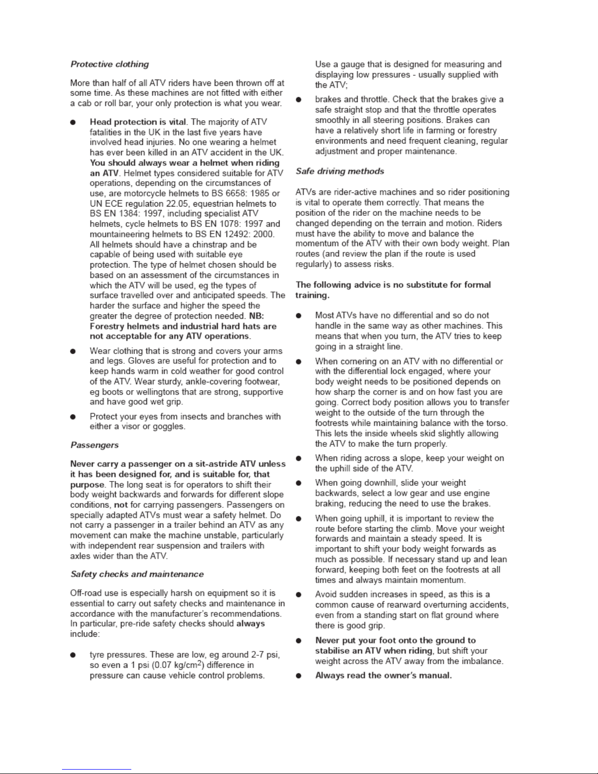
IN THE INTEREST OF SAFETY:
DO NOT
This symbol means WARNING or CAUTION Personal safety or damage will be at
risk if these instructions are ignored. Most accidents are caused by neglect or
carelessness; Avoid needless accidents by following the safety precautions
listed below.
Page 9

9
1. DO – Follow Engine manufactures guidelines.
2. DO – Ensure all spectators are a safe distance away when operating.
3. DO – Carry out regular servicing and checks before use.
4. DO – Clear cutting area from potential damaging components e.g. stones etc.
5. DO – Reduce speeds when working on hillsides or rough terrain
6. DO – Be aware components can be hot after operation
7. DO – Follow any towing guidelines stated by towing vehicle manufacturer.
8. DO – Show some caution when filling the tank with petrol, especially if engine
components are hot.
9. DO – Ensure all safety decals are in good condition, replace any that are damaged.
10. DO – Keep hands and feet away from rotating blades
11. DO – Ensure mower is in transport position before transporting to and from the workplace
3
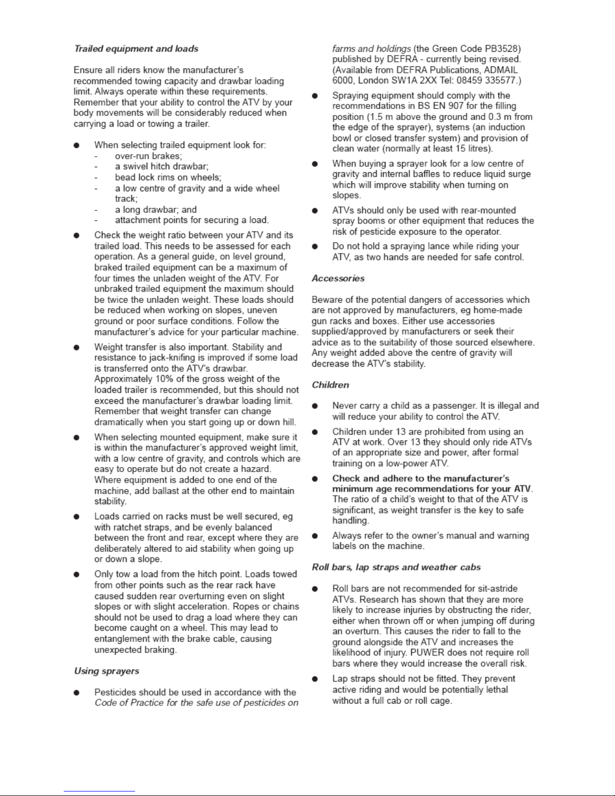
IN THE INTEREST OF SAF
ETY:
DO
Page 10

10
INSTRUCTION / WARNING DECALS
4
The above decals should be located on your TRM120. If any of the above decals
are not located on your TRM120 or are damaged in any way contact Logic for some
replacement decals before use.
Page 11

11
Ensure the vehicle used to lift and transport the TRM120 has the necessary lifting and loading
capacity. Follow all vehicle manufactures guidelines for lifting. Unladen weights are clearly
marked on the Manufactures plate attached to the TRM120 deck. Check the lifting weight
complies with the vehicle lifting limits
When lifting the TRM120 for transporting / delivery purposes always ensure to locate the lifting
straps on each of the four corners ensuring the straps/chains are all the same length before
lifting, or if using forklift tines ensure the mower is secure on the tines before lifting.
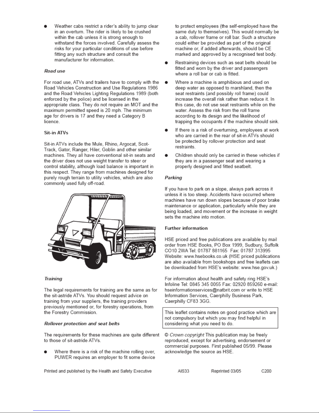
The LOGIC TRM ROTARY MOWER is designed to give safe and dependable service if
operated according to instructions and intended use.
Read and understand this manual before operating the mower, as failure to do so could result in
personal injury or equipment damage.
The amount of grass or weeds to be cut dictates the forward speed; slow forward speeds give
better results in most cases. Ensure you follow the procedure below.
NORMAL FORWARD SPEED (1 kph - very heavy use - 10 kp
h - very light use)
Start off in the slowest speed possible; ensure the mower is working efficiently with the engine
set at maximum RPM and not labouring. (If this is not possible due to very heavy cutting
conditions, raise cutting height of blades and be prepared to go over twice with machine set
lower on 2nd pass, leave at least 24 hours in between 1st and 2nd cut to allow grass to dry out)
Increase forward speed until the RPM of the engine starts to slow down (This is working the
engine too hard for conditions) - slow down, let the engine regain full RPM and go through the
same process but stop short of speed which made engine labour previously. It is important
always to listen to note of engine to ensure engine and mower are working efficiently, slow
down or stop once engine starts to labour.
FAILURE TO DO THIS WILL RESULT IN CLUTCH SLIP AND
ULTIMATELY SEVERE DAMAGE TO THE CLUTCH AND DRIVE BELTS.
TRANSPORTING & LIFTING
5
OPERATING PRINCIPLES
6
When moving from normal working conditions to heavier cutting, it may be evident that
the engine dies down and loses revs. SLOW DOWN IMMEDIATELY to allow the engine revs
to build up again to normal working speed if engine does not recover stop the engine
immediately by using the kill switch cord remove the blockage and follow all engine staring
procedures. Follow the procedure detailed above in “Normal Forward Speed”. Expected
forward speed will be much lower in heavy conditions.
Page 12

12
7.1 – BEFORE USE INSPECTION:
Ensure that all nuts, bolts and fittings are secure before using the TRM120.
Ensure the tyres are in good condition and have the correct pressures.
Ensure the swivel hitch is in good condition; replace any worn or damaged parts.
7.2 – ATTACHMENT TO TOWING VEHICLE
Any suitable vehicle can tow the Logic TRM120 normally by its 50mm swivel hitch coupling.
Ensure the hitch is securely attached to the towing vehicle and the handle indicator points to
“OK” before moving the vehicle.
Use the raise and lower levers to lift the TRM120 clear of the ground. Drive around for a short
period of time in a wide open space to ensure you become familiar with the operating width and
handling of the machine.
7.3 – ADJUSTING THE MOWER
MOWER ENGINE MUST BE SWITCHED OFF WHEN ADJUSTING THE MOWER!
DRAWBAR PITCH ADJUSTMENT
The hitch attachment height of the towing vehicle can vary. To accommodate this adjustment, a
screw link is located on the drawbar. This should be lengthened or shortened so that the cutting
deck is horizontal to level ground. (This ensures a better cutting efficiency)
1. Unlock the locking nut (A)
2. Lengthen the link to lower the front of the deck or shorten to raise the deck, by turning
handle (B).
3. Once the deck is level, re-tighten locking nut (A).
SETTINGS &
ADJUSTMENTS
7
A
B
Page 13

13
QUICK OFFSET DRAWBAR
Remove the ‘R’ clip and locking pin; slide the drawbar to the desired position and reposition the
locking pin into the securing hole as shown below. There are 4 hole positions as shown below
that allow the mower to move to an ‘Off set’ position. Hole position 1 (Zero offset) would mean
the mower would follow the towing vehicle straight behind, if the position was then changed to
hole 4 this would mean the mower would move by approx 700mm to the right hand side (Based
on the below image)
MOWER CUTTING HEIGHT
The main cutting height adjustment is achieved by using the spring assisted handles on either
side of the deck.
There are 5 cutting heights available, including transport position (See below diagram)
1. Remove ‘R’ clip and pin (A)
2. Raise or lower the spring assisted lever to the new cutting height replace the pin in the
correct hole (Ensure both height adjusters are on the same setting, never operate the mower
with different height settings) Ensure the deck runs parallel to the ground see drawbar
adjustment section in this manual.
3. Replace ‘R’ clip and pin (A)
A
Locking Pi
n
& ‘R’
clip
Hole Settings
(4 positions)
Transport position
1 4 3 2
Example: Setting number 4 is used the mower will be
700mm ‘Offset’ to the right
Page 14

14
STARTING THE ENGINE
READ AND UNDERSTAND THE ENGINE OPERATORS MANUAL BEFORE USE
OBSERVE ALL SAFETY PRECAUTIONS; KEEP HANDS AND FEET AWAY FROM
THE ROTOR AND OTHER MOVING PARTS.
KEEP SPECTATORS AT A SAFE DISTANCE
1. Make sure there is a gap between the blades and the ground / crop
2. Select an area clear of loose debris.
3. Set the engine choke (if necessary) and suitable idling speed with the throttle.
4. Place one foot on top of the deck body to give a firm and balanced position. Pull the starter
cord firmly, allowing the cord to return to the housing slowly (one or two strong pulls should
start the engine).
5. After a few seconds warming up at idling speed, move the throttle to the factory pre-set max
engine RPM.
ELECTRIC START
Push button electric start engine options can be supplied if required. Simply hitch up the
mower, connect the electrical supply plug to the ATV socket and press the ignition button to
start the mower. Observing all the precautions mentioned above in ‘Starting the mower’.
REMOTE THROTTLE CONTROL
When a remote throttle control option is fitted, normally to the rear carrier frame of an ATV or
other suitable position on the towing vehicle, it gives the operator the facility of controlling the
mower engine from the operating position.
If the throttle is altered to increase the engine R.P.M beyond the recommended level, the
guarantee will become invalid. In addition to this, cutting efficiency will be reduced, fuel
consumption will increase and excessive vibration could be caused, resulting in a potential
danger to personnel and damage to components.
Page 15

15
THROTTLE PARK
The mower deck is fitted with a throttle park. To use the throttle park clip the throttle to the
bracket as shown below.
DO NOT USE THE THROTTLE PARK DURING OPERATION. THE THROTTLE
SHOULD BE POSITIONED NEAR THE OPERATOR DURING WORKING CONDITIONS.
THROTTLE PARK IS FOR STORAGE WHEN THE MOWER IS NOT IN USE ONLY
STOPPING THE ENGINE
When stopping the mower after a period of heavy use. Run the machine at half working speed
in a stationary position for at least 4 minutes to allow the drive belts/clutch to cool down.
Shut the throttle down to lowest RPM and switch off engine.
1. Show caution to hot parts e.g. engine exhaust, belts etc after engine is switched off.
2. When the mower has cooled down (Min1hr after last used) Ensure all grass has been
removed from engine cooling fins, drive belt area and rotors before operating again.
TRANSPORT POSITION
When the mower is being moved from one site to another it is advisable to raise the deck to the
highest position (See section called ‘mower cutting height’)
The engine must be stopped and the blades at a standstill before adjusting to the transport
position. (Transport position is the highest deck setting available).
Remove any crop particles from the deck before leaving the field. Never move from one site to
another with the engine running. Ensure the mower drawbar has been adjusted to allow the
mower to run directly behind the towing vehicle and is not in an offset position
NB: TRM – Rotary mower is not road legal, and should not be used on public roadways.
If you have any specific questions regarding mowing or adjusting the TRM120 to suit your
conditions please contact Logic
Page 16

16
All servicing should be carried out by qualified mechanics. Contact your Local dealer for more
details.
MAINTENANCE
8
Maintenance Schedule
Maintenance Operation:
Hourly Daily Weekly Seasonal
Engine (See Engine manufacturer’s manual)
SEE ENGINE MANUFACTURES MANUAL
Remove excess crop gathered on deck
Remove excess crop wrapped around rotors
Visual check to ensure nothings loose
Grease Drive Pulleys
Grease Height Adjuster
Grease Rear Roller
Grease Rotor Bearings
Drive belt tension
Tyre Pressures
Rotor Bearing inspection
Wheel Bearing Inspection
Oil coupling
Coupling Bush Wear
Check All Fasteners are tight and intact
Safety projectile deflectors front/rear (inspection)
Safety Decals intact
Safety Guards Intact
Sharpen Rotor Blades
Check Metal Fatigue
Clutch Wear / Function
Maintenance History
Service Date: Service Performed: By:
Page 17

17
ENGINE MAINTENANCE
Refer to engine manufacturer’s manual, for servicing and maintenance of the engine.
EXCESS CROP BUILD UP
Remove all crop deposits from the deck and engine area. Build up of crop deposits could result
in heat build and fires. NB: Disconnect the spark plug lead.
Remove any crop that is wrapped around the rotors on the underside of the deck, as shown
below. Raise the deck to its max height to assist access to the rotor shafts.
VISUAL CHECK
Make a visual check around the mower, check for missing / loose parts or damaged / worn
components. All faults must be either repaired or replaced.
DRIVE BELT ADJUSTMENT
1. Remove drive belt covers by removing the 3x mounting bolts on each guard.
2. Slacken 4 x engine mounting plate bolts, so the plate is free to move (A) See figure 8.1
3. Tighten the tensioner bolt (B) until the tension on the belt allows one and a half the belts
thickness in deflection ether side of the belt centreline (C). Belt deflection should always
be tested on the longest and central part of the belt.
4. Replace drive belt covers.
NB: New drive belts stretch a little after the first f
ew hours of use; so be sure too check belt
tension after the first few hours of use. (DO NOT OVER TIGHTEN DRIVE BELTS)
Replace any worn or cracked drive belts. Only use Logic specified drive belts as
replacements.
Always stop and switch off the engine and wait for the rotor blade movement to
stop before carrying out any inspection or adjustment. CAUTION some Drive belts /
Drive pulleys could be hot after use
Page 18

18
TYRE / PRESSURES
DO NOT EXCEED RECOMMENDED TYRE PRESSURES
1. Remember that temperature affects pressures: in cold weather the pressure needs to be
higher than in hotter temperatures.
2. Never adjust the pressure immediately after driving because driving heats up the tyres.
There are many individual causes of tyre troubles. However, the three abuses which will cause
most problems and the greatest costs are under-inflation, overloading and speeding. When you
check the tyre pressures also look for bumps and bulges in the side of the tyre or tread. Check
the tyres for cuts, slits or cracks, nails or foreign objects embedded in the side of the tyre or
tread. Check the tread for excess wear. Replace or repair any defect or fault with tyres before
use.
ROTOR BEARING INSPECTION
NB: Disconnect the spark plug lead.
Rotate each rotor shaft by hand and feel for any roughness in the bearings. Also try to pull the
shaft from side to side if any movement is found check all mounting and blade bolts are tight
and repeat the test. If symptoms persist strip down the rotor-housing unit and inspect bearings.
C
B
A
A
Figure 8.1
WHEEL/TYRE TYPE
RECOMMENDED PRESSURE
CARLISLE AT 20 x 7 – 8 7 - 10 PSI
KINGSTYRE 16 x 6.50
- 8
28 PSI (Max)
Page 19

19
WHEEL BEARING INSPECTION
Jack one side of the mower body up, so the wheel is just off the ground. Rotate the wheel by
hand, and check the wheel alignment. To check the bearings, try to move the wheel from left to
right and feel for any play in the bearings (A), ensure the wheel-locating bolt is tight before you
start and follow any jacking procedures. If any play is found remove the wheel and inspect
bearings. Replace any faulty bearings.
OIL COUPLING / COUPLING BUSH WEAR
Check coupling for signs of damage or wear, swivel the coupling 360 degrees and check that
the yellow bushes aren’t to worn. Replace any warn or damaged parts. Oil the coupling regularly
GENERAL INSPECTION
Check the mower to ensure all fasteners are tight and all safety guards / chains are intact and
fitted securely. Check all safety-warning decals, Replace any defected guards or decals.
SHARPEN ROTOR BLADES
To remove the individual blades:
1. Disconnect the spark plug.
2. Block the blade to prevent it from rotating by using a block of wood. (A)
A
B
A
Page 20

20
3. Remove the blade bolt (B)
4. Remove the blade, replace or sharpen the blade.
5. Reinstall the blade ensure the blade-securing bolt has a torque setting of 60ft/lbs.
6. Inspect any fasteners before re-assembly, replace if necessary.
7. Reconnect spark plug.
SPECIFICATIONS
TRM120B12*** TRM120H13***
Max machine width
(CARLISLE) :1790mm
(KINGSTYRE) : 1770mm
Max machine height
(CARLISLE): 730mm
(KINGSTYRE): 690mm
Max machine length
2190mm
Max cutting width
1200mm
Cutting range
(CARLISLE): 20mm – 160mm
(KINGSTYRE): 20mm – 120mm
Weight
(CARLISLE): 168kg
(KINGSTYRE): 166kg
(CARLISLE): 173kg
(KINGSTYRE): 171kg
Hitch:
50mm swivel coupling
Drawbar
Adjustable and Offset facility (approx 700mm Offset)
Raise / Lower
Manual spring assisted lift handles
Wheel / Tyres
(CARLISLE AT 20 x 7 – 8): 4-10 Psi
(KINGSTYRE 16 x 6.50
–
8):
28 Psi
FOR REPAIRS BEYOND THE MINOR ADJUSTMENTS LISTED ABOVE CONTACT
YOUR LOCAL DEALER
Page 21

21
9:
PARTS DIAGRAM
Page 22

22
Item
Part Number
Description
01
TRM120-01A Mower Deck
02
TRM120-14 Rear Deflector Flap
03
FRP06014 Rivet Mono 6.5mm X 14mm (2mm X 9.5mm Panel)
04
FSH12035 S/Screw Hex Head M12 X 35
05
-09L Rear Discharge Deflector L/H
05
TRM120-09R Rear Discharge Deflector R/H
06
-22 Rear Clamping Plate
07
S216-1013 Self Locking Nut
08
S216-1012 Blade (Lg412)
09
S216-1026 Spindle
10
LRM120-41 Key Outer Pulley
11
S216-1025 Bearing Cover
12
FSH10030,FWF10,FNN10 S/Screw M10 X 30, Flat Washers, Nyloc Nut
13
MF120-1048 Bearing
14
TA102-03 Grease Nipple
15
S216-1024 Hub
16
S216-1023 Spacer
17
FSH10025,FWF10,FNN10 S/Screw M10 X 25, Flat Washers, Nyloc Nut
18
TRM120-23 Clamp plate front Outer
19
TRM120-12 Deflector front Flap: End
20
TRM120-13 Deflector front Flap: Centre
21
TRM120-24 Clamp plate front Centre
22
FSH08025,FWF08,FNN08 S/Screw M8 X 25, Flat Washers, Nyloc Nut
23
WP05,FRP03010 Manufacturers Plate Universal, Rivet Pop 1/8 X 3/8
24
WS01 Sticker: Logic – 240 X 75 MM
25
WS146 Sticker: Mower Hazard Sticker
26
WS147 Sticker: TRM120
27
S215-096 Sprocket Spacer Bush 2 MM
28
S215-091 Castor Bottom Collar 12 MM
29
S215-092 Castor Bush 6 MM
30
LRM120-38 Pulley Single V ‘B; Section 4”
31
S216-1027 Washer
32
S216-1015 Self Locking Ring Nut
33
FBH716200 Bolt Hex Head 7/16 UNF X 2”
34
LRM123-01 Top Hat Washer
35
TRM120-39 2 Vee Centrifugal Clutch (Purple Springs)
36
LRM123-04 Clutch Spacer 12 MM
37
LRM120-39 Pulley Double V ‘B’ Section 4”
38
WS36 Sticker: Design Right
39
Sticker: Ser No: N/Plate 50.4 X 19.1
40
-1054 Dust Cap
41
10
S/Screw M10 X 25, Spring Washer, Repair –
Washer
42
-1048 Outer Wheel Bearing
43
WT142 WL/TY 16 X 650 – 8 Kingstyre
Page 23

23
Item
Part Number
Description
43
WL/TY 20 X 700 – 8 Carlisle/Max 4
44
MF120-1063 Spacer
45
TRM120-20A Guard Rail
46
FSH08030,FWF08,FNN08 S/Screw M8 X 30, Flat Washers, Nyloc Nut
47
TRM120-37 Spring Tension 5.38 MM Dia
48
-25LA Axle L/H
48
-25RA Axle R/H
49
TRM120-10 Wheel Arm Locking Pin
50
-S100 Sleeve Flat Grey 31.75 MM X 9.5
51
FSH12035,FWF12,FNN12 S/Screw M12 X 35, Flat Washers, Nyloc Nut
52
TRM120-02LA Height Adjuster Bracket Assembly L/H
52
TRM120-02RA Height Adjuster Bracket Assembly R/H
53
FCG03064 Clip R3 X 64 MM
54
FNN20 Nut Nyloc M20
55
LRM123-05 Belt V BX49
56
FBH16090,FWF16,FNN16 Bolt M16 X 90, Flat Washers, Nyloc Nut
57
TRM120-05A Drawbar Mounting Assembly
58
MFG104-15 Turnbuckle
59
TRM120-03A Drawbar Offset
60
WS82 Sticker: Mfg300 Warning
61
CM100-04 Drawtube
62
CM100-03A Bush Nylon
63
TRM120-16A Drawbar Assembly
64
CM100-01A Thrust Washer
65
C900 Coupling 50 MM H/D Winterhoff
66
FBH12065,FNN12 Bolt M12 X 65, Nyloc Nut
67
FBH12070,FNN12 Bolt M12 X 70, Nyloc Nut
68
TRM120-11 Drawbar Locking Pin
69
FBH16065,FWF16,FNN16 Bolt M16 X 65, Flat Washers, Nyloc Nut
70
LRM120-02A Engine Mounting Stool
71
TRM120-07L Transmission Guard L/H
71
TRM120-07R Transmission Guard R/H
72
WS118 Sticker: Grease Symbol
73
FSH08015,FWF08 S/Screw M8 X 15, Flat Washer
74
WS103 Sticker: Keep Wheel Nuts Tight
75
WS11 Sticker: Mow General Warning
76
FSH08010,FWS08,FWF08 S/Screw M8 X 10, Washer Spring, Washer Flat
77
LRM120-37 Plastic Plug-Kill Switch Mounting
78
LRM126-01A Kill Switch Assembly
79
-013A Engine Mounting Plate
80
S/Screw M10 X 60, Flat Washers, Nyloc Nut
81
LRM123-03 Key Engine Pulley
Page 24

24
This Logic Manufacturing product is guaranteed against faulty workmanship and materials for a
period of 6 months from the date of purchase.
On Engine-Powered equipment, the engine manufacturer’s guarantee will apply, any claims
being subject to their terms and conditions.
All claims must be made in writing within 28 days of the alleged failure.
All claims must be made through the dealer who originally supplied the machine.
Any defective parts must be kept for inspection and if requested, sent to the factory or dealer.
The customer must bring equipment for repair to the dealer.
This guarantee becomes void if unauthorised modifications have been made, or if parts not
manufactured, supplied or approved by Logic Manufacturing have been fitted to the machine.
We accept no liability for normal wear and tear, misuse or abuse, or where recommended
maintenance has not been carried out.
All guarantee work must be authorised by Logic manufacturing prior to any work being done.
Work carried out without our consent may not be reimbursed.
LOGIC MANUFACTURING PR
ODUCTS OWNER
10
Item
Part Number
Description
82
FCF06 Clip Fix Rubber Lined 6.0mm
83
FSH06020,FWF06 S/Screw M6 X 20, Flat Washer
84
S216-048 Durite Heavy Duty Terminal
85
S216-047 Stadium Clip 21 MM OD
86
FSH06035,FWF06 S/Screw M6 X 35, Flat Washer
87
MFG109-04 Clip Base Plate
88
LRM123-03 Cable Clip
BRIGGS & STRATTON:
89
ME-S034 Switch Rocker On/Off 12v 6A B/S
90
FSC08035,FWF08,FNN08 Screw C/Sunk M8 X 35,Flat Washers, Nyloc Nut X2
91
EBV121 Engine B+S 12.5hp Recoil Start
92
TRM127-01 Throttle Control 2.7mt Fast/Slow Only
HONDA:
93
FSC516100,FWF08 Screw C/Sunk Sckt 5/16 X 1”, Flat Washer
90
Screw C/Sunk M8 X 35, Flat Washers, Nyloc Nut
91
EHV131 Engine Honda 13hp Electric Start
91
EHV132 Engine Honda 13hp Recoil Start
92
LRM127-01 Throttle Control 2.7metre
S216-060A Battery Lead ATV End (Electric Start Only)
Page 25

25
DECLARATION OF CONFORMITY
DECLARATION OF CONFORMITYDECLARATION OF CONFORMITY
DECLARATION OF CONFORMITY
93 / 44 EEC
93 / 44 EEC93 / 44 EEC
93 / 44 EEC
LOGIC MANUFACTURING LTD
Foundry Industrial Estate
Bridge End
HEXHAM
Northumberland
Product Type: TRM120 – ROTARY MOWER RANGE
C
overed By Technical File Number: CE – LRM120
Serial Number:
Standards and Regulations Used:
The Supply of Machinery (Safety) Regulations 1992
HSE Guide Lines on ATV Equipment (Agric Sheet No. 11)
HSE Guide lines On Agricultural Mowers (Agric Sheet No.25)
Place of Issue: United Kingdom
Name of Authorised Representative: P. G. RIDLEY
Position of Authorised Representative: RESEARCH & DEVELOPMENT MANAGER
D
eclaration,
I declare that as the authorised representative, the above information in relation to the
Supply / manufacture of this product, is in conformity with the stated standards and other related
documents following the provisions of 93/68EEC directives
Signature of Authorised Representative
Date: 02/04/07
 Loading...