

Page 1
Technical Manual 1.00, PNM-220
Technical Manual for the
PNM-220
Version 1.00
Logic IO ApS. Ph: (+45) 7625 0210
Holmboes Allé 14 Fax: (+45) 7625 0211
8700 Horsens Email: info@logicio.com
Denmark www.logicio.com / www.rtcu.dk
Page 1 of 16
Page 2

Technical Manual 1.00, PNM-220
Introduction
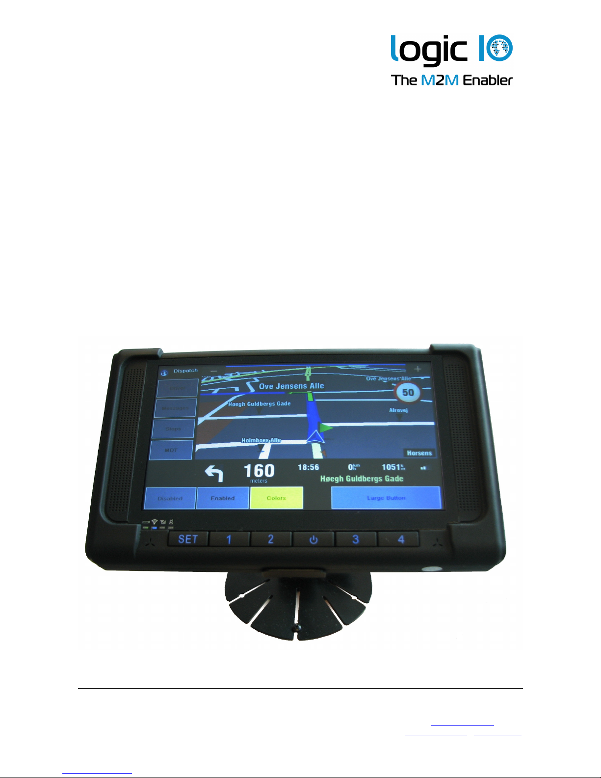
The Logic IO PNM-220 is a complete solution using the Navigation and Messaging
Platform designed for the most demanding and professional fleet management
applications. The PNM-220 device is a ruggedized 7-inch, easy to read, screen optimized
for finger touch usage. A powerful processor and generous RAM and flash ensure a
delightful experience. The PNM-220 also offers support for connecting up to two cameras
used for rear-view or cabin view etc.
The PNM-220 comes with the PNM software/maps pre-installed and interface cables for
the RTCU MX2i pro/pro+. Ready to go!
This technical manual describes the installation of the PNM-220, and the technical details
of the system. For controlling the PNM device from the VPL user application, please refer
to the RTCU online help, and for detailed information on the NMP software interface,
please refer to the documentation of the Navigation and Messaging Platform.
The NMP software and the Sygic maps are pre-installed on the PNM device and activated
according to the user agreement. Please refer to the NMP software documentation for
detailed information.
Logic IO ApS. Ph: (+45) 7625 0210
Holmboes Allé 14 Fax: (+45) 7625 0211
8700 Horsens Email: info@logicio.com
Denmark www.logicio.com / www.rtcu.dk
Page 2 of 16
Page 3

Technical Manual 1.00, PNM-220
Table of Contents
Introduction.............................................................................................................................2
Table of Contents...................................................................................................................3
Graphical view........................................................................................................................4
Package overview..................................................................................................................5
PNM-220 Overview............................................................................................................6
Typical System Connection................................................................................................8
Typical Application.................................................................................................................9
Interfacing to the RTCU MX2i Pro/Pro+.............................................................................9
Analog camera interface..................................................................................................10
Interfacing to the RTCU IDE Simulator................................................................................11
Technical Specifications......................................................................................................12
Appendix A – Mounting the dashboard bracket...................................................................13
Appendix B – Installation and removal of the SD card........................................................15
Logic IO ApS. Ph: (+45) 7625 0210
Holmboes Allé 14 Fax: (+45) 7625 0211
8700 Horsens Email: info@logicio.com
Denmark www.logicio.com / www.rtcu.dk
Page 3 of 16
Page 4
Technical Manual 1.00, PNM-220
Graphical view
Logic IO ApS. Ph: (+45) 7625 0210
Holmboes Allé 14 Fax: (+45) 7625 0211
8700 Horsens Email: info@logicio.com
Denmark www.logicio.com / www.rtcu.dk
Page 4 of 16
Page 5

Technical Manual 1.00, PNM-220
Package overview
The PNM-220 package includes the following items:
Quantity Item Description
1 PNM-220 device Windows CE6.0 device.
1 Mounting Bracket PNM-220 device mounting bracket
1 8 GB SD-CARD With pre-installed software.
Typically already installed in the PNM-220
device.
1 PNM-220 series device cable Connection cable between PNM device and
the PNM interface box
Logic IO ApS. Ph: (+45) 7625 0210
Holmboes Allé 14 Fax: (+45) 7625 0211
8700 Horsens Email: info@logicio.com
Denmark www.logicio.com / www.rtcu.dk
Page 5 of 16
Page 6

Technical Manual 1.00, PNM-220
PNM-220 Overview
Interface Description
Power No built-in functionality. May be used for power by the application.
SET User-defined key.
Key 1 User-defined key.
Key 2 User-defined key.
Key 3 User-defined key.
Key 4 User-defined key.
LEDs 1 power LED and 3 status LEDs
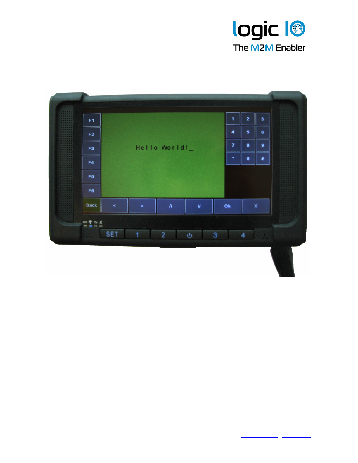
Touch Screen To interact with the application using finger touch or attached stylus
Please note that all the keys and the status LEDs on the PNM-220 device can be
configured by the VPL application. Please refer to the RTCU IDE online-help for further
information.
Logic IO ApS. Ph: (+45) 7625 0210
Holmboes Allé 14 Fax: (+45) 7625 0211
8700 Horsens Email: info@logicio.com
Denmark www.logicio.com / www.rtcu.dk
Touch
Screen
Power
Set
Key2Key1
Key3
Key4
Speaker
Speaker
LEDs
Page 6 of 16
Page 7

Technical Manual 1.00, PNM-220
Interface Description
Reset Button Reset button of the PNM-220 device
Stylus Stylus for the touch screen
Interface Cable
Connector
The connector for the PNM-220 device interface cable
SD card compartment
Cover
The cover for the compartment where the SD card reader is
located.
The PNM-220 device can be reset asynchronously using the reset button, located at the
backside of the device. Please do not use the button unless it is absolutely needed.
The stylus can be used for more accurate handling of the touch screen. As the touch
screen is resistive, a finger can be used as well. The stylus is mounted tightly at the
backside of the device. It can be removed by sliding it out sideways.
Logic IO ApS. Ph: (+45) 7625 0210
Holmboes Allé 14 Fax: (+45) 7625 0211
8700 Horsens Email: info@logicio.com
Denmark www.logicio.com / www.rtcu.dk
Mounting
Jack
Stylus
Interface
Cable
Connector
USB and
SD Card
Cover
Reset
Button
Page 7 of 16
Page 8

Technical Manual 1.00, PNM-220
Typical System Connection
A typical system installation is illustrated below:
The application in the RTCU unit controls the power to the PNM device.
Unlike the other PNM devices with external interface box, this device will only shut down
directly while it is communicating with the RTCU. If asked to shut down while the
connection is lost, it will either wait for a timeout1 before shutting down, or it can be
manually shut down by pressing the reset button on the back. Note that the reset button
should not be used unless absolutely necessary, as it cuts the power immediately, while
the two other ways allows the device to perform a controlled shut down.
1 See the setting DisconnectTimeout in the Navigation and Messaging Platform User Guide.
Logic IO ApS. Ph: (+45) 7625 0210
Holmboes Allé 14 Fax: (+45) 7625 0211
8700 Horsens Email: info@logicio.com
Denmark www.logicio.com / www.rtcu.dk
Page 8 of 16
RTCU Unit
External
Power Supply
Page 9

Technical Manual 1.00, PNM-220
Typical Application
This is a quick start guide to connect the PNM device to the supported RTCU units. It is
easy to install the PNM system on location with the supplied cable for the RTCU MX2i
pro/pro+. The following section will describe the system connection to the supported
RTCU units.
Interfacing to the RTCU MX2i Pro/Pro+
The data cable with the RJ-45 connector needs to be connected to the 8-pole serial port 2
connector on the RTCU unit. The power cable, with the read and black wires at the end,
must be supplied from an external DC supply.
An example of the connection to RTCU MX2i pro is shown in the drawing below.
1. Connect the PNM device interface cable to the PNM device.
2. Connect the RJ-45 data cable of the PNM device interface cable to the serial Port 2
of the RTCU MX2i pro.
3. Connect the power supply to the power connector cable. The power requirement is
9..32VDC. The black wire is (-) and the red wire is (+).
Note that the power to the PNM device is controlled by the RTCU MX2i pro
application. The module will not power on unless the RTCU MX2i pro is powered on
and the application enables the module. Please refer to the RTCU IDE online help
for enabling and using the NMP interface.
Logic IO ApS. Ph: (+45) 7625 0210
Holmboes Allé 14 Fax: (+45) 7625 0211
8700 Horsens Email: info@logicio.com
Denmark www.logicio.com / www.rtcu.dk
Page 9 of 16
9..32VDC
Data cable
Power cable
Page 10

Technical Manual 1.00, PNM-220
Analog camera interface
PNM-220 offers connection for up to two analog cameras using the BNC connectors
available at the PNM device interface cable. Analog camera #1 must be connected to the
cable labeled with BNC-1 and analog camera #2 must be connected to BNC-2.
The use of the cameras is under full control of the VPL application. Please consult the
RTCU IDE on-line help for additional information.
Logic IO ApS. Ph: (+45) 7625 0210
Holmboes Allé 14 Fax: (+45) 7625 0211
8700 Horsens Email: info@logicio.com
Denmark www.logicio.com / www.rtcu.dk
Page 10 of 16
Page 11

Technical Manual 1.00, PNM-220
Interfacing to the RTCU IDE Simulator
The PNM-220 is supported by the RTCU IDE Simulator. In order to connect the PNM-220
series device to the PC, an optional cable with the order code RT-PNM-PC is needed.
1. Connect the PNM device interface cable to the PNM device.
2. Connect the RJ-45 data cable of the PNM device interface cable to the combiner.
3. Connect the combiner with one of the available serial ports on the PC with the
PNM-220 PC interface cable.
4. Connect the power supply to the power cable. The power requirement is 9..32VDC.
The black wire is (-) and the red wire is (+).
Note that the power to the PNM device is controlled by RTCU IDE application. The
module will not power on unless the RTCU IDE Simulator is running and the user
application enables the module. Please refer to the RTCU IDE online help for
enabling and using the NMP interface.
Logic IO ApS. Ph: (+45) 7625 0210
Holmboes Allé 14 Fax: (+45) 7625 0211
8700 Horsens Email: info@logicio.com
Denmark www.logicio.com / www.rtcu.dk
Page 11 of 16
9..32VDC
Power cable
Data cable
PC Cable
Page 12

Technical Manual 1.00, PNM-220
Technical Specifications
Logic IO ApS. Ph: (+45) 7625 0210
Holmboes Allé 14 Fax: (+45) 7625 0211
8700 Horsens Email: info@logicio.com
Denmark www.logicio.com / www.rtcu.dk
Page 12 of 16
Page 13
Technical Manual 1.00, PNM-220
Appendix A – Mounting the dashboard bracket
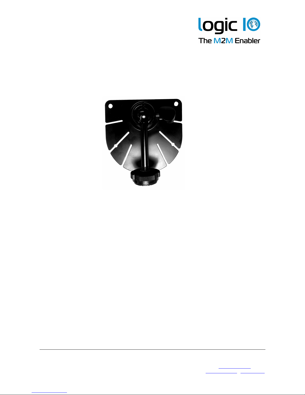
A dashboard mounting bracket is included for easy installation of the PNM-220 device. In
the following the mounting of the bracket will be described.
1. Loosen the adjustment screw handle, and set the bracket arm to an upraised
position
2. Loosen the securing screw until there is a gap between the bracket part and the
metal plate.
3. Place the metal part on top of the bracket at the starting point of the mounting jack
on the back side of the PNM device. Slide the bracket part until it is at the desired
position. Fasten the securing screw. Please note the orientation of the bracket
Logic IO ApS. Ph: (+45) 7625 0210
Holmboes Allé 14 Fax: (+45) 7625 0211
8700 Horsens Email: info@logicio.com
Denmark www.logicio.com / www.rtcu.dk
Bracket
Adjustment
screw handle
Page 13 of 16
Page 14

Technical Manual 1.00, PNM-220
4. The vertical angle and rotation of the PNM device can be adjusted using the screw
handle on the bracket.
5. Remove the protection paper of the adhesive and place the bracket on a proper
location at the dashboard. Please make sure that the bracket is mounted on the
correct location with the correct angle.
Logic IO ApS. Ph: (+45) 7625 0210
Holmboes Allé 14 Fax: (+45) 7625 0211
8700 Horsens Email: info@logicio.com
Denmark www.logicio.com / www.rtcu.dk
Mounting jack
Mounting jack
starting point
Securing
screw
Page 14 of 16
Page 15

Technical Manual 1.00, PNM-220
Appendix B – Installation and removal of the SD card
The SD card reader is hidden in a compartment for protection purpose.
Access the compartment with the SD-CARD reader as follows:
1. Unscrew the two M2 screw from the compartment cover.
2. Pull up the cover slightly until you see the gap.
3. Take out the cover
Please note that the compartment on the opposite side of the terminal is reserved and
should not be accessed.
For closing the cover, please follow the steps above at reverse order.
Logic IO ApS. Ph: (+45) 7625 0210
Holmboes Allé 14 Fax: (+45) 7625 0211
8700 Horsens Email: info@logicio.com
Denmark www.logicio.com / www.rtcu.dk
gap
Pull up
Pull out the cover
Page 15 of 16
Page 16

Technical Manual 1.00, PNM-220
A side view of the terminal when the cover is removed is as follows:
Interface Description
Mini USB Port Mini USB 2.0 service port.
USB Port USB host port.
Earphone jack Connection with a stereo earphone
SD card slot SD card reader for application / map card included with the product.
Logic IO ApS. Ph: (+45) 7625 0210
Holmboes Allé 14 Fax: (+45) 7625 0211
8700 Horsens Email: info@logicio.com
Denmark www.logicio.com / www.rtcu.dk
Mini USB port
USB port
Earphone
jack
SD card
slot
Page 16 of 16
 Loading...