

Page 1
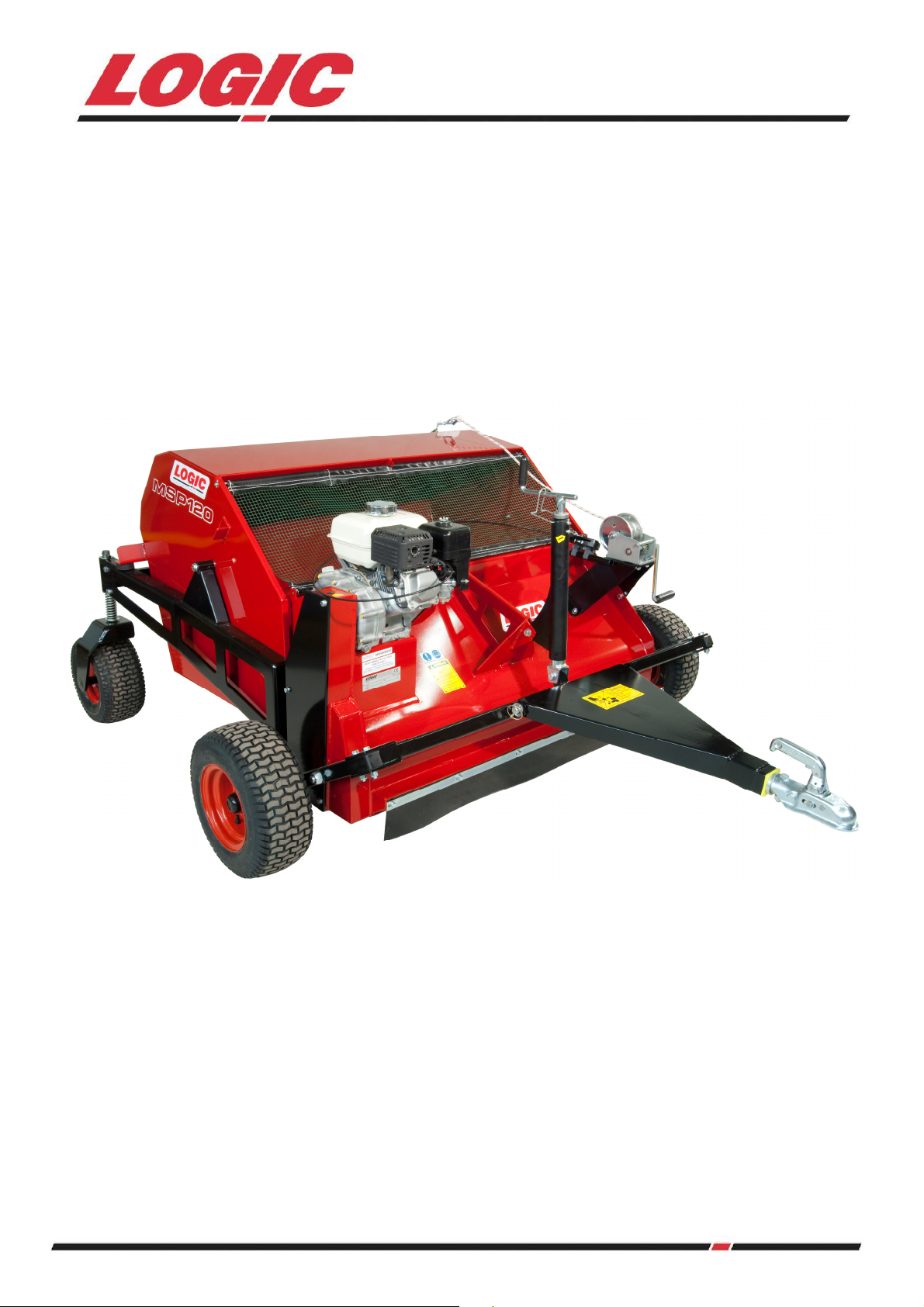
MSP120
SWEEPER / COLLECTOR
USER MANUAL
WM2-MSP120
Page 2

INDEX
Section:
1 Introduction 3
2 In the interest of safety: DO NOT 9
3 In the interest of safety: DO 9
4 Instructions / Warning Decals 10
5
6
6.1 Attaching to ATV (or suitable vehicle) 11
6.2 Brush Height Adjustment 12
6.3 Tine Bar Height Adjustment 13
6.4 Emptying The Hopper 14
7 Maintenance / Service 16
7.1 Brush Maintenance and Replacement 17
8 Specification 18
9 Parts Information 19-21
10
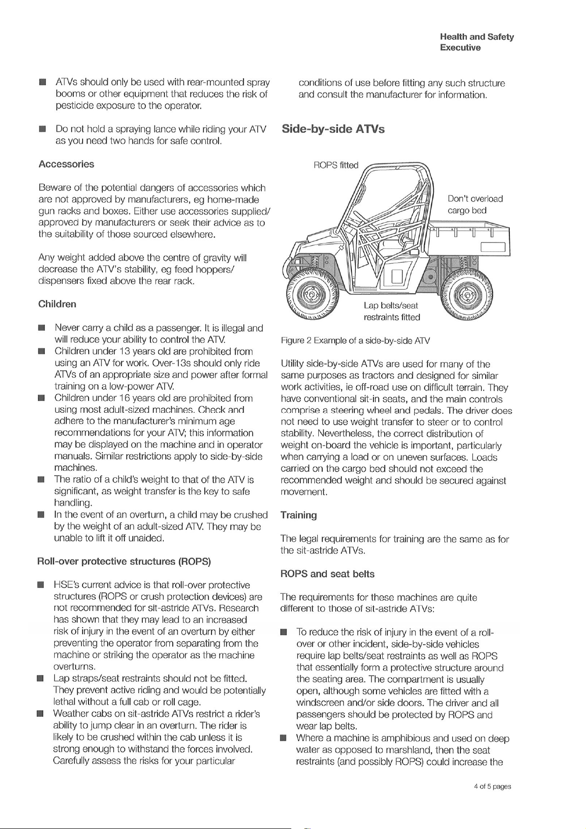
HSE Information Sheet 4-8
6.5 Starting The Sweeper / Collector 15
Description:
Transport Lifting and Storage 11
Operating Instructions and Adjustments 11
Logic Manufacturing Product Owner 22
LOGIC: Declaration of conformity 23
Page
No:
2
Page 3

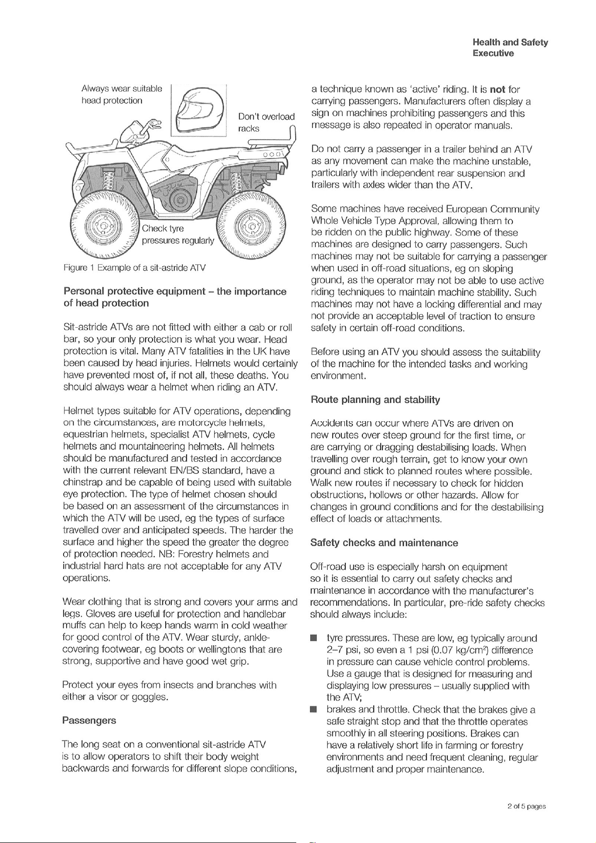
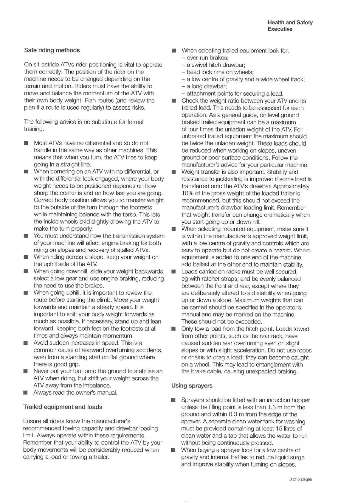
INTRODUCTION 1
With the purchase of your MSP120 sweeper collector you have made an excellent choice.
This machine should give first class service for many years, if used correctly, and maintained as
described in this manual.
The MSP120 is constructed from quality materials and components to ensure first class service for a
long time when used correctly.
This manual also has important H.S.E information and Guidelines.
If after reading this manual you have any queries, please get in touch as we will be pleased to help.
NORTH & EXPORT SOUTH
LOGIC MANUFACTURING LTD LOGIC MH LTD - New Whiteway Works,
Foundry Industrial Estate Fossecross Industrial Estate
Bridge End, Hexham Chedworth. Cheltenham
Northumberland NE46 4JL Gloucestershire GL54 4NW
Tel: 01434 606661 Fax: 01434 608143 Tel: 01285 720930 Fax:01285 720840
E-mail: sales@LogicToday.co.uk E-mail: sales@LogicToday.co.uk
www.LogicToday.co.uk www.LogicToday.co.uk
3
Page 4
4
Page 5
5 6 7 8
Page 6
Page 7
Page 8

Page 9

This symbol means WARNING or CAUTION. Personal safety or damage will be at risk if
!!!!
these instructions are ignored. Most accidents are caused by neglect or carelessness.
Avoid needless accidents by following the safety precautions listed below.
2 IN THE INTEREST OF SAFETY: DO NOT
DO NOT – Operate the MSP120 unless you have read this entire manual.
DO NOT – Operate the MSP120 if any part of the sweeper is defective, replace any parts before
use.
DO NOT – Touch moving parts.
DO NOT – Never carry passengers.
DO NOT – Exceed sensible towing speeds. (Max 15mph)
3 IN THE INTEREST OF SAFETY: DO
DO – Follow all manufacturer’s guidelines.
DO – Attach the MSP120 to a suitable towing vehicle.
DO – Follow all manufacturer’s service instructions.
DO – Be aware of travelling conditions – Do not exceed sensible speeds.
DO – Follow all safety instructions in this manual.
DO – Make sure all persons are a safe distance when operating the MSP120, especially when
operating in areas used by the public.
DO – Make sure all nuts bolts and fittings are secure before using and check at regular intervals
during operation.
DO – Avoid excessively steep slopes or adverse ground conditions.
DO – Have a clean working area before starting the machine.
DO – Stop the engine and wait for all movement to stop before inspecting the machine.
DO – After hitting an obstacle, stop the machine and check for damage.
DO – Use suitable ear protection.
9
Page 10

4 INSTRUCTIONS / WARNING DECALS
The above decals should be located on your MSP120. If any of the above decals are not
!!!!
located on your MSP120 or are damaged in any way contact Logic for some
Replacements decals before use.
10
Page 11

TRANSPORT LIFTING AND STORAGE 5
Ensure the vehicle used to lift and transport the sweeper has the necessary lifting and loading
capacity. Follow all vehicle manufacturer’s guidelines for lifting.
When lifting the MSP120 for transporting / delivery purposes always ensure to locate the lifting
straps on each of the four corners ensuring the straps/chains are all the same length before lifting,
or if using forklift tines ensure the sweeper is secure on the tines before lifting.
OPERATING INSTRUCTIONS AND ADJUSTMENTS 6
The LOGIC SWEEPER/COLLECTOR is designed to give safe and dependable service if operated
according to instructions and intended use.
Read and understand this manual before operating the unit, as failure to do so could result in
personal injury or equipment damage.
When used with an ATV or compact tractor, ear defenders should be worn. Under normal working
conditions a noise level of 78 decibels would be usual, in this case protection is advised.
INITIAL CHECK
a. Make sure that all nuts, bolts and fittings are securely fixed, and that all packaging materials e.g.
wire bands, tape etc have been removed.
b. Check that there is oil in the engine and petrol in the tank.
6.1 ATTACHING TO THE ATV (OR SIMILAR SUITABLE VEHICLE)
The MSP120 Sweeper is simply attached by the 50mm ball coupling
The remote throttle control should be fitted to the ATV rear carrier frame using the plastic clips to
clip onto a suitable point of the carrier frame, taking note to position the throttle quadrant in an
easily accessible position for the operator's hand.
On vehicles where there is no such carrier frame, a simple bracket may need to be fabricated to
mount the throttle holder.
Care should be taken to ensure the throttle cable is not kinked or close to any hot surfaces, use the
cable holder clip in a similar way to the throttle quadrant to hold the cable in a secure manner.
MSP120R MODELS
The MSP120R models come with a rope (tipping rope) attached to the hopper for tipping.
Position the tipping rope handle at a suitable point and secure with the plastic clip provided.
MSP120W AND WT MODELS
When the sweeper is remove from the towing vehicle the remote throttle should be attached to the
throttle park mounted on the winch bracket.
11
Page 12

6.2 BRUSH HEIGHT ADJUSTMENT
The height of the brush and subsequent contact on the ground is controlled by the height
adjustment jack. See figure 1.
As a general rule the brush should be just touching the ground. Each situation will be different
depending on what the surface is like and the type of material to be collected.
Too much contact with the ground will either damage the surface or increase the wearing on the
brush bristles leading to poor sweeping performance and early replacement.
ADJUSTING OF BRUSH HEIGHT
1. Unclip the height adjuster locking clip.
2. Turn the jack handle, anti-clock wise to increase the height of the brush, or clockwise to
reduce the height.
3. Try a test run to see if the brush is correctly positioned to perform effectively,
4. Clip the locking clip back over the adjuster handle to secure the jack in the desired position.
(this stops the handle turning)
Figure 1
RE –ADJUSTING OF BRUSHING HEIGHT
If the wrong height setting has been selected before starting, or different ground conditions require
another setting, it is easy to re-adjust.
a. Stop the engine and wait for the brush rotor to come to a standstill.
b. Follow the same procedure as described in the adjustment section above 1-4.
12
Page 13

6.3 TINE BAR HEIGHT ADJUSTMENT (MSP120WT ONLY)
The tine bar is engaged and disengaged with the main height adjuster for the brush.
To maximise the effectiveness of the tines they should be set so that the tips of the tines are just
off the ground. This will ensure that any dried droppings will be disturbed by the tines and give the
brush a better chance of picking them up.
If the tines have too much contact with the ground this will either damage the surface or increase
the wearing on the tines leading to early replacement.
ADJUSTING OF TINE HEIGHT
1. Slacken the hand wheel on each end of the tine bar. See figure 2.
2. Push the hand wheel back to enter the vertical slot.
3. Select one of the three height setting required by lifting or lowering the tine bar using the
handles provided. then pull the hand wheel forward again.
4. Tighten the two hand wheels to secure the tine bar in the desired position.
Figure 2
RE – ADJUSTING OF TINE BAR HEIGHT
As the brush of the sweeper wears, the tine bar may need adjusting to ensure it is being effective.
Follow steps 1 to 4 above.
13
Page 14

6.4 EMPTYING THE HOPPER
The operator can clearly see when the hopper is full through the hopper mesh.
It is advised that the hopper is emptied at the end of each sweeping session. This will stop the
contents drying out in the hopper which could be difficult to tip out.
HOPPER EMPTYING
1. Drive to the area where you would like to empty the contents of the hopper.
2. Wind the winch to tip the hopper forward till it hits the stops. See figure 3
3. Slowly drive forward to clear the ejected heap.
4. Wind the winch back to lower the hopper back down ready to sweep again.
Figure 3
If emptying is desired away from the field being swept the sweeper should be lifted
!!!!
on the main height adjuster to ensure the brushes and tines are not damaged during
transport over rough terrain such as gateways.
14
Page 15

6.5 STARTING THE SWEEPER / COLLECTOR
a. Observe all safety precautions, keep hands and feet away from rotor and other moving parts.
b. Keep spectators at a safe distance.
c. Make sure there is a gap between the brush and the ground.
d. Select an area clear of loose debris that could be picked up.
e. Set the engine choke, and suitable idling speed with the throttle
f. Pull the starter cord firmly, allowing the cord to return to the housing slowly (one or two strong
pulls should start the engine).
g. After a few seconds warming up at idling speed, move the throttle to the slowest setting
possible, to achieve a satisfactory performance.
Remember, slow brush speeds will increase the life of the bristles and reduce the amount of dust
created.
If the throttle is altered to increase the engine R.P.M beyond the factory pre-set
!!!!
maximum level, the guarantee may become invalid. In addition to this, brushing
efficiency will be reduced, fuel consumption will increase, and excessive vibration could be
caused resulting in a potential danger to personnel and damage to components
FORWARD SPEED
The amount of debris to be brushed dictates the gear selection and forward speed, slow forward
speeds give better results in most cases.
Start off in the slowest speed possible, then increase gradually to find the optimum working speed.
The machine should never be driven at excessive speeds which could cause bouncing, resulting in
poor brushing finish and danger to the operator and any personnel nearby.
MOVING FROM ONE SITE TO ANOTHER
When moving from one area to another close by, reduce the engine speed to idling using the remote
throttle control so that the brush comes to a standstill.
When approaching the next area to be swept, increase the throttle setting to the pre determined
position which will increase the engine speed and automatically engage the brush drive.
Excessive transit speed could cause castor wheel vibration and vehicle instability.
!!!!
15
Page 16

7 MAINTENANCE / SERVICE
SERVICE SCHEDULE
DAILY WEEKLY MONTHLY
Check tyre pressures
Check condition of tyres
Visual check to ensure nothing is loose
Check all nuts and bolts
Oil the coupling mechanism and check for wear
Check for debris wrapping on the brush shaft
Grease brush bearings and height adjuster
Grease rear caster bushings
Check brush and spring tine* wear
Check and lubricate the drive chain
Check oil levels in the engine and other periodical
checks according to the engine handbook
* When tines are fitted (MSP120WT only)
!!!!
The engine should be stopped and all brush rotor movement stopped before any
maintenance checks are carried out.
TYRE / PRESSURE
Tyre pressure for: KINGSTYRE Front 16 x 6.5 - 8 (Max 28 Psi)
Rear 13 x 6.5 - 6 (Max 23 Psi)
DO NOT exceed recommended tyre pressures.
!!!!
Remember that temperature affects pressures: in cold weather, the pressure needs to be higher
than in higher temperatures.
Never adjust the pressure immediately after driving, because driving heats up the tyres.
There are many individual causes of tyre troubles. However, the three abuses which will cause most
problems, and the greatest costs, are under-inflation, overloading and speeding. When you check
the tyre pressures also look for bumps, bulges in the side of the tyre or tread. Check the tyres for
cuts, slits or cracks, nails or foreign objects embedded in the side of the tyre or tread. Check the
tread for excess wear. Replace or repair any defect or fault with tyres before use.
SWIVEL HITCH HOUSING
Check coupling for signs of damage or wear, swivel the coupling 360 degrees and check that the
bushes are not too worn. Replace any worn or damaged parts.
Oil the 50mm coupling; follow the diagrams on the hitch to ensure oil is applied correctly.
16
Page 17

7.1 BRUSH MAINTENANCE AND REPLACEMENT
The brush sections are designed to give a long period of use, when adjusted correctly.
The rate of wear will vary depending on the surfaces being brushed. Under normal circumstances,
the complete set of brush sections would be changed at the same time, to ensure an even sweeping
performance.
If a brush section has been damaged through striking an object, it should be changed immediately.
Correct installation of brush sections on the main spindle, See figure 3.
Figure 3
DRIVE CHAIN MAINTENANCE AND ADJUSTMENT
Always switch off the engine and wait for all brush movement to stop before carrying out any
inspection or adjustment.
The chain drive guard should be removed before any inspection or adjustment.
Correct chain tension is automatically regulated by a spring loaded tensioner which should only
need turning or replacing after many hours use.
Regular lubrication of the chain is very important. The nature of work increases the
!!!!
need for frequent use of the chain lubricant provided. The lubricant is applied
through the hole on top of the chain sprocket housing, covered with a rubber grommet.
The engine should be at idling speed when the lubricant is applied. Once every eight
hours use, should be sufficient.
17
Page 18

8 SPECIFICATIONS
Max machine width 1880mm
Max machine Height 1630mm 1100mm
Max machine length (Not including drawbar) 1800mm
Max working width 1.2mm (48”)
Weight 235kg 245kg 255kg
Hitch:
Type 50mm swivel ball hitch
Height range 150mm to 600mm off ground level
Raise / Lower Manual lift
Wheel / Tyres KINGSTYRE Front 16 x 6.5 –8 Rear 13 x 6.5 – 6
Max speed 15mph
Spring tines:
Diameter of tine 8 mm
Tine spacing 100 mm
Number of tines 11
MSP120R MSP120W MSP120WT
18
Page 19

9 PARTS DIAGRAM
19
Page 20

Item Part Number Description
C900 Coupling 50mm H/D Winterhoff
001
FBH12065,FNN12 Bolt M12 X 65 Mm,Nut Nyloc M12
002
CM100-01A Swivel Hitch Thrust Washer
003
MSP120-06A Drawbar Panel
004
FBH12070,FNN12 Bolt M12 X 70,Nyloc Nut M12
005
CM100-03A Swivel Hitch Nylon Bush
006
CM100-04 Swivel Hitch Draw Tube
007
FPL06 Pin Linch 6mm
008
MSP120-31A Drawbar Pin
009
FBH08090,FWF08,FNN08 Bolt M8 X 90,Washer M8,Nyloc Nut M8
010
MSC120-43 Brush Clamping Strip
011
MSC120-44 Brush
012
MSP120-62A Brush Spindle
013
SSQ006K Square Key Steel 1/4” X ¼”
014
FSH10030,FWF10,FNN10 S/Screw M10 X 30,Washers M10,Nyloc Nut M10
015
MSP121-06 Spring Tine
016
FBH10080,FWF10,FNN10 Bolt M10 X 80,Washer M10,Nyloc Nut M10
017
MSP121-01A Tine Bar Bracket
018
FSH10030,FWR10030,FNN10 S/Screw M10 X 30,Washer Repair M10 X 30,Nyloc Nut M10
019
FSH10030,FWR10030,FWS10 S/Screw M10 X 30,Washer Repair M10 X 30,Spring M10
020
FHW1055 Hand wheel M10 X 55 Od Female
021
MSP121-03A Tine Bar Angle
022
FNN20 Nyloc Nut M20
023
MSP120-73A Chain Guard Cover
024
FBH10025,FWS10,FWR10030 Bolt M10 X 25,Spring Washer M10,Repair Washer M10
025
MSP120-08 Drive Chain ½” X 47 Links
026
MSC120-48 Spindle Drive Sprocket
027
MSU-B100 Bearing T 1025 25tr Cast
028
FSH10035,FWF10,FNN10 S/Screw M10 X 35,Washer M10,Nyloc Nut M10
029
MSP120-21A Rotor Bearing Shield
030
FSH08025,FWF08,FNN08 S/Screw M8 X 25,Washer, Flat, Nyloc Nut M8
031
FBH08020,FWS08,FWF08 Bolt M8 X 20,Spring Washer M8,Flat Washer M8
032
MSP120-05A Chain Guard Base
033
MSP120-14A Sweeper Hood
034
FSG06015 Grubscrew Skt M6 X 15
035
MSC120-47 Engine Sprocket
036
FSP06012 S/Screw Tri-Lobe Pozi Hd M6 X 12
037
FBC10050,FWF10,FNN10 Bolt/Nut Cup Sq M10 X 50,Washer M10,Nyloc Nut M10
038
MSP120-16 Chain Tensioner Block
039
MSP120-57 Spring Chain Tensioner
040
MSC120-51 Chain Tensioner
041
MSP120-32LA Castor Mounting Bracket L/H
042
WT112 Wl/Ty 13 X 650-6 Kingstyre
043
FBH10025,FWF10,FNN10 Bolt M10 X 25,Washer M10,Nyloc Nut M10
044
MSP120-03LA Hopper Frame Side Member L/H
045
FWF26 Washer M26 X 47 X 2 Thick
046
MSC120-72 Spring
047
20
Page 21

Item Part Number Description
TA102-03 Grease Nipple
048
FSH12085,FWF12,FNN12 S/Screw M12 X 85,3 Washers, Nyloc Nut M12
049
MSP120-38A Hopper Rear X Member
050
FSH12025,FWF12,FNN12 S/Screw M12 X 25,Washer M12,Nyloc Nut M12
051
MSU-R005 Rubber Buffer 60 X 19 X M12
052
FPS10060 Pin Spirol M10 X 60
053
FCG01025 Clip R 1.6 X 25
054
MSP120-58 Hopper Mesh Bottom Bar
055
FCG01025,FWF08 Clip R 1.6 X 25,Washer M8
056
MSP120-59A Hopper Mesh Top Bar
057
MSP120-64M Hopper Net
058
MSP120-01A Hopper
059
MSP120-70A Hopper Tip Anchor
060
FSH08025,FWR08025,FWF08,FNN08 S/Screw M8 X 25,Washer Repair+ Flat, Nyloc Nut M8
061
FBH08040,FWF08,FNN08 Bolt M8 X 40 ,Washers M8,Nyloc Nut M8
062
EHH052 Engine H0nda 5.5 Hp 2/1 Red
063
MSP120-69 Winch Rope
064
MSP120-67 Winch 454kg Ratio 3.5:1
065
MFG109 Throttle Control Kit 2 Meter
066
FSH06035,FWFO6 S/Screw M6 X 35,Washer M6
067
MFG109-04 Clip Base Plate
068
S216-047 Stadium Clip 21 MM OD
069
FSH06020,FWF06 S/Screw M6 X 20,Washer M6
070
S216-048 Durite Heavy Duty Terminal
071
WT142 Wl/Ty 16 X 650-8 Kingstyre
072
FIP040040 Insert Plastic 40 X 40 X 26-4 MM
073
MSP120-23A Front Wheel Mounting
074
MFP302 Height Adjuster
075
FBH12065,FWF12,FNN12 Bolt M12 X 65,Washer M12,Nyloc Nut M12
076
MSP120-43A Height Adjuster Cross Bar
077
FBH10070,FWF10,FNN10 Bolt M10 X 70,Washer M10,Nyloc Nut M10
078
MSP120-35 Plygene Clamping Bar
079
MSP120-63 Skirt Plygene
080
MSP120-07A Winch Mount
081
FWF20037 Washer Flat M20 X 37 X 2 MM Thick
082
MSP123-01A Tipping Rope Anchor
083
21
Page 22

10 LOGIC MANUFACTURING PRODUCTS OWNER
This Logic Manufacturing product is guaranteed against faulty workmanship and materials for a
period of 6 months from the date of purchase.
On Engine-Powered equipment, the engine manufactures guarantee will apply, any claims being
subject to their terms and conditions.
All claims must be made in writing within 28 days of the alleged failure.
All claims must be made through the dealer who originally supplied the machine.
Any defective parts must be kept for inspection and if requested, sent to the factory or dealer.
The customer must bring equipment for repair to the dealer.
This guarantee becomes void if unauthorised modifications have been made, or if parts not
manufactured, supplied or approved by Logic Manufacturing have been fitted to the machine.
We accept no liability for normal wear and tear, misuse or abuse, or where recommended
maintenance has not been carried out.
All guarantee work must be authorised by Logic manufacturing prior to any work being done. Work
carried out without our consent may not be reimbursed.
22
Page 23

DECLARATION OF CONFORMITY
93 / 44 EEC
LOGIC MANUFACTURING LTD
Foundry Industrial Estate
Bridge End
HEXHAM
Northumberland
Product Type: MSP120R/ W/ WT
Covered By Technical File Number: CE – MSP120
Serial Number:
Standards and Regulations Used:
The Supply of Machinery (Safety) Regulations 1992
HSE Guide Lines on ATV Equipment (Agric Sheet No. 11)
Place of Issue: United Kingdom
Name of Authorised Representative: S A WEIR
Position of Authorised Representative: PRODUCT DEVELOPMENT MANAGER
Declaration,
I declare that as the authorised representative, the above information in relation to the
supply / manufacture of this product, is in conformity with the stated standards and other related
documents following the provisions of 93/68EEC directives
Signature of Authorised Representative
Date: 19/05/2010
23
 Loading...