

Instruction Sheet
PICTURE FRAMING
Model F500-2
Dual DrivE Elite Point Driver
Operating Instructions
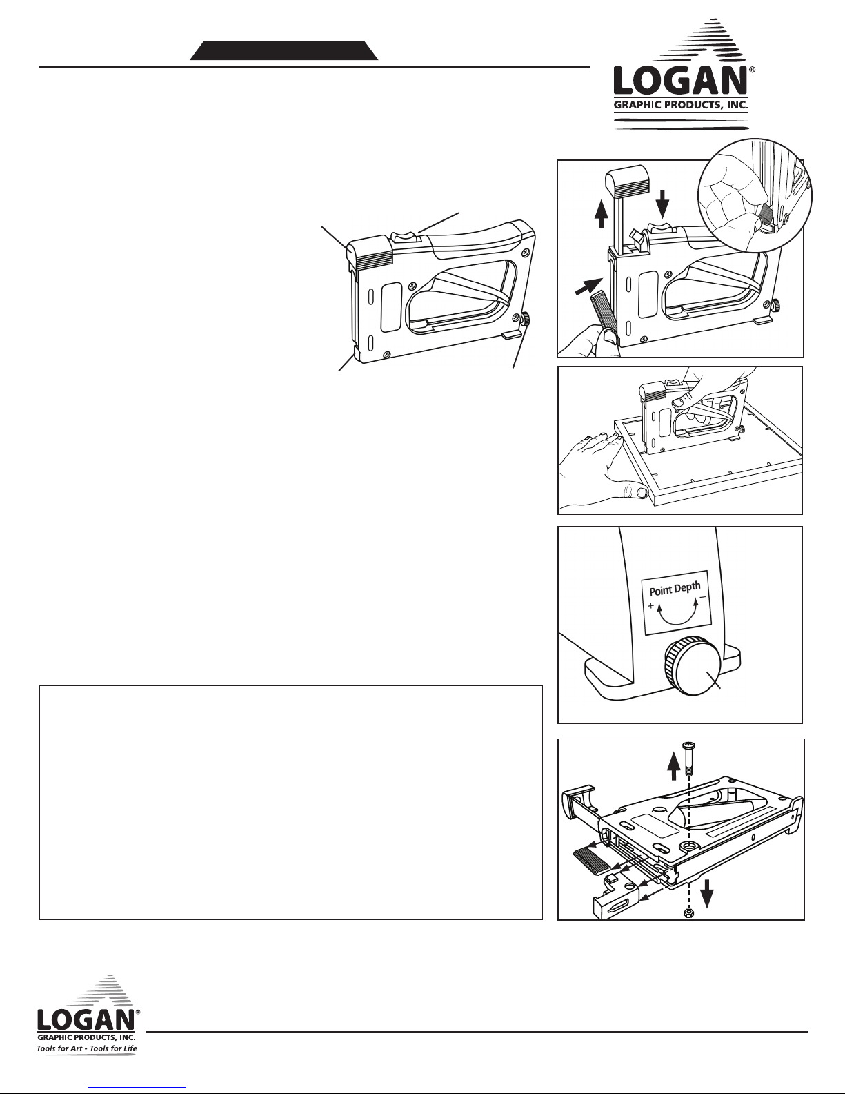
Loading Points
1. Press release button
2. Pull up cover
3. Install point strips with point facing
forward
NOTE:
down into nose piece.
4. Slide cover closed (Fig. 1)
Operation
1. Hold outside of frame
2. Press driver nose against inside frame
3. Keep drive flat on material - DO NOT
4. Squeeze trigger to insert point
5. Space points 6” apart, 3” from corners
Adjust Point Depth
1. Turn adjustment screw to increase
Make sure points are inserted
LIFT OR ANGLE
(Fig. 2)
tension for hardwoods or decrease
tension for softwoods.
(Fig. 3)
Identification
Cover Release Button
Point Loading Cover
Nose
Point Jammed
1. Remove points
2. Remove nose screw and nut
3. Remove nose piece and discard
jammed point (Fig. 4)
Replacement Points
Use only authentic Logan Points
F53 - Flex (600) F54 - Rigid (600)
F55 - Flex (2500) F56 - Rigid (2500)
Point Depth Adjustment
Fig. 1
3.
Fig. 2
Fig. 3
1.
2.
Troubleshooting
IF GUN JAMS & NO LONGER FIRES POINTS
• Keep 1” or higher stack of points in gun at all times
• Make sure you are using authentic Logan rigid or flexible points (F53, F54, F55, F56).
• Make sure points are loaded and seated correctly. Try removing and re-loading the point strip.
• To remove a point jammed in the nose piece, reference the instructions to remove the nose piece, clear
it and re-install it.
• If point does not leave the gun, try reducing or tightening tension.
• Check to see that main body screws holding two halves of the tool together are not loose. If necessary,
re-tighten with Phillips screwdriver.
IF THE POINT BENDS
• If flexible inserts are bending or not staying in the wood, try increasing the tension or switch to rigid
points.
• Try reducing the tension if handle is hard to pull.
Logan Graphic Products Inc. 1100 Brown Street, Wauconda, IL 60084 1-847-526-5515 1-800-331-6232
Fig. 4
1.
Adjustment Screw
2.
3.
LoganGraphic.com
N1329 1-15
Instruction Sheet
PICTURE FRAMING
Model F60
DUST COVER TRIMMER
Operating Instructions
Blade install: (Fig. 1)
1. Determine right hand or left hand usage.
2. Remove nut and three (3) blades.
3. Separate and install one blade, sharp edge down.
4. Slide cover to “safe” when not using and “blade” when ready to use.
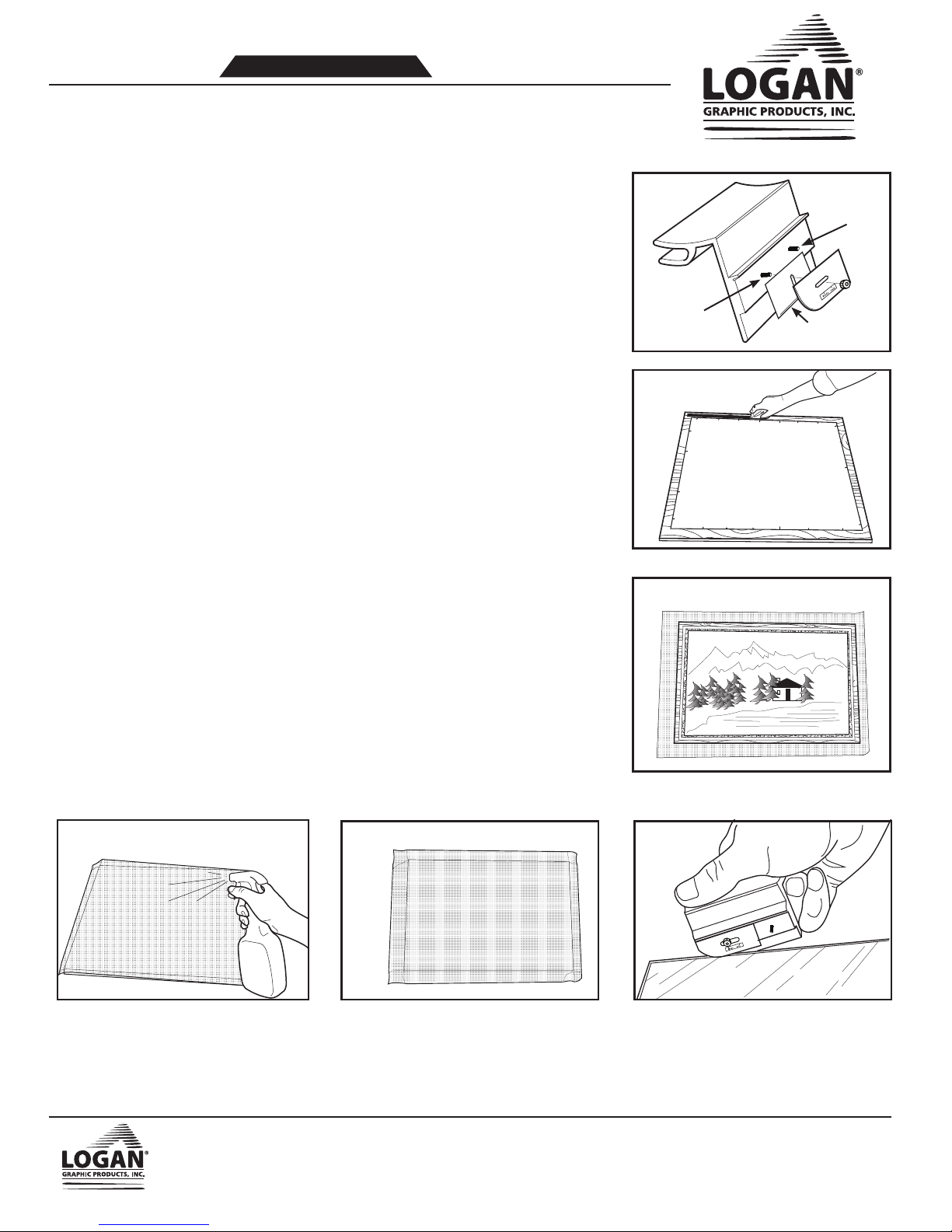
Apply dust cover:
1. Using double sided tape, ATG tape or glue, apply continuous line around
back of frame about 1/8” from edge. (Fig. 2)
2. Cut a piece of Kraft paper (30, 40, or 50 lb available at craft stores) that
is larger than overall outside of frame by a minimum of 1”.
3. Lay paper flat onto table and drop the frame straight down onto the
paper with taped side down and artwork side facing up. (Fig. 3)
4. Using water in a spray bottle, completely dampen Kraft paper evenly. As
water dries, the paper will shrink tight. (Fig. 4) NOTE: Use a hairdryer to
decrease drying time.
Fig. 1
Right hand
usage
mount side
Fig. 2
Fig. 3
Left hand
usage
mount
side
Sharp Edge
Artwork Side Up
5. Crease paper along the edges of frames. (Fig. 5)
6. Using trimmer, start beyond edge of a corner, hold on slight angle up
against frame edge. Draw trimmer along edge to trim. (Fig. 6)
7. Repeat for other three sides.
Fig. 4
Fig. 5
Fig. 6
Logan Graphic Products Inc. 1100 Brown Street, Wauconda, IL 60084 1-847-526-5515 1-800-331-6232
www.logangraphic.com
L2222 01/15
Instruction Sheet
PICTURE FRAMING
Installing Hanging
Wire and Bumper Pads
Several options exist for hanging your artwork, but the preferred method is picture hanging wire because it provides the greatest ease and flexibility with artwork of
any size. Traditionally screweyes have been used for attaching hanging wire to the frame, but in recent years strap hangers with D‑rings have grown in popularity
because they lie flat against the back of the dust cover and won’t scratch the wall.
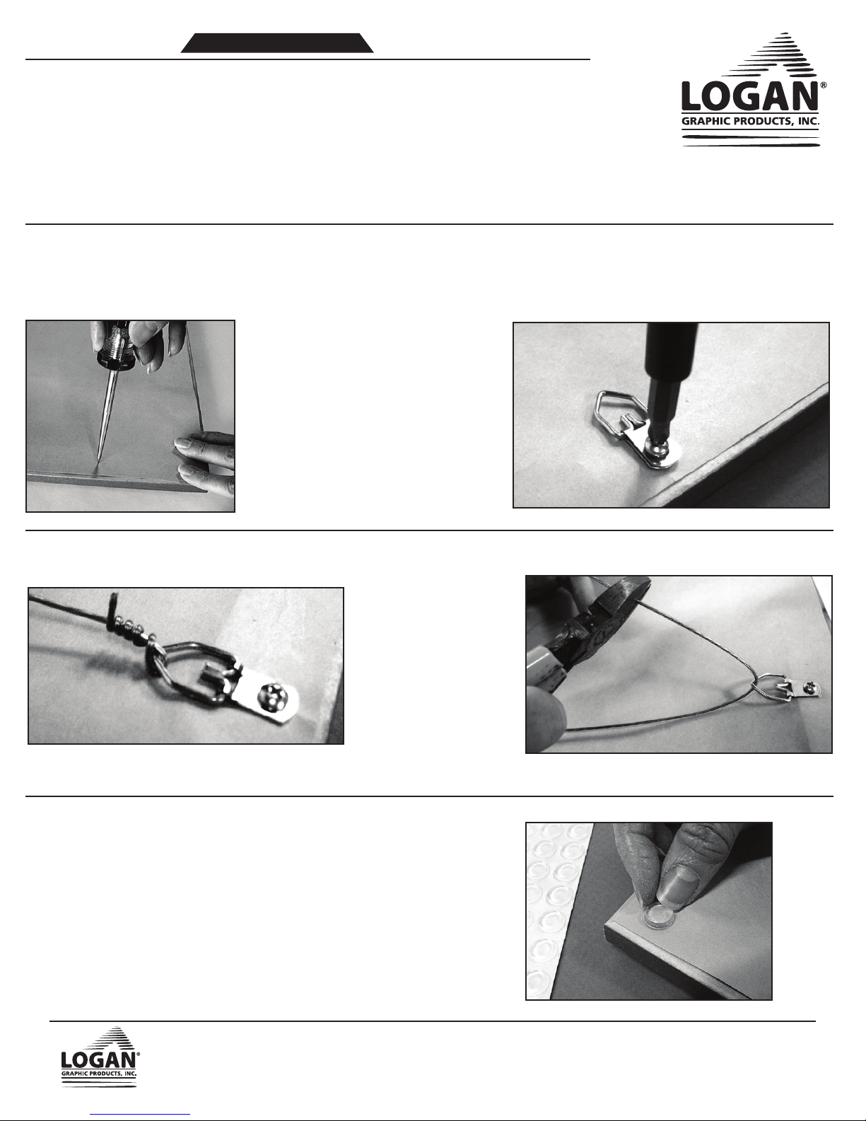
Installing D-Rings
To position D‑Rings, measure about one‑third down from the top of the frame and mark the location. Do this on both sides. Zerlon‑coated hanging wire comes in
three strengths: 19 lb., 25 lb. and 43 lb. Each strength is a measure of the weight‑bearing capacity of the wire. If the framed piece is too heavy for the wire, the wire
will unravel, pulling free of the hangers, regardless of the complexity of the knots used.
To attach D‑Rings to soft or medium wood frames,
make a pilot hole in the back of the frame with a
scratch awl. Turn the screw into the wood with a
screwdriver (Fig. 1). To attach a D‑Ring into hard‑
wood frames, drill a hole with a power drill and attach
the screw with a power screwdriver (Fig. 2).
Fig.1
Fig.2
Installing Wire
To attach the wire, insert one end
through the D‑Ring of your strap
hanger (Fig. 3) and coil it around
itself several times.
Stretch the wire across to the
other hanger and pull it taut.
Allow for about 3‑5 inches of
wire to feed through the D‑ring
on the opposite side. Clip off
the excess wire (Fig. 4) and coil
Fig.3
the remaining wire around itself
several times.
Attaching Bumper Pads
For a nice finishing touch, attach self‑adhesive bumber pads to each corner on the back of your
frame. These will prevent the frame from scratching the wall. The pads simply peel off a sheet of
release paper and adhere to the dust cover (Fig. 5).
Fig.4
Logan Graphic Products Inc. 1100 Brown Street, Wauconda, IL 60084 1‑847‑526‑5515 1‑800‑331‑6232
www.logangraphic.com
Fig.5
N1328 01/15

 Loading...