


85-Ton Open Loop Power Swivel

Contents
Overview................................................................................2
Uses ......................................................................................2
Important Safety Information .................................................2
Construction ..........................................................................3
Power Swivel
Control Units ......................................................................3
Basic Power System ..........................................................4
Hydraulic System ...............................................................4
Power Unit .........................................................................4
Trailer-Mounted Unit .......................................................4
Skid-Mounted Unit ..........................................................4
Installation .............................................................................4
Rig Up ................................................................................4
Pre-operation Start-up Procedure ......................................5
Operation ...........................................................................6
General Rules ....................................................................
Air Controls ........................................................................6
Electric Controls .................................................................
Maintenance ......................................................................7
Power Swivel Maintenance ................................................7
Lubrication ......................................................................
Breaking-In .....................................................................7
Storage ...........................................................................7
Replacing the Floating Washpipe Assembly
and Packing
Power Unit Maintenance ....................................................7
Swivel Disassembly .............................................................10
Swivel Reassembly .............................................................16
Troubleshooting ...................................................................18
Specications ......................................................................19
Assembly .....................................................3
..............................................................7 – 8
6
6
7
Drawings and Schematics
Floating Washpipe Assembly ................................................8
Swivel Head Assembly:
Front V
iew ........................................................................12
Side View .........................................................................13
Top View ..........................................................................14
Section A-A – Through Gear Train) ..................................
Swivel Head Dimensions .................................................
Bumper Pull Trailer-Mounted Unit .......................................22
Skid-Mounted Unit ...............................................................23
Hydraulic System and Controls ...........................................24
Torque Controller (for Air and Electric Controls) ..................25
Assembly and Replacement Parts Lists
Floating Washpipe .................................................................8
Power Swivel .......................................................................11
Power Unit ...........................................................................21
Torque Controller .................................................................25
1 • Logan 85-ton Open Loop Power swivel
15
20

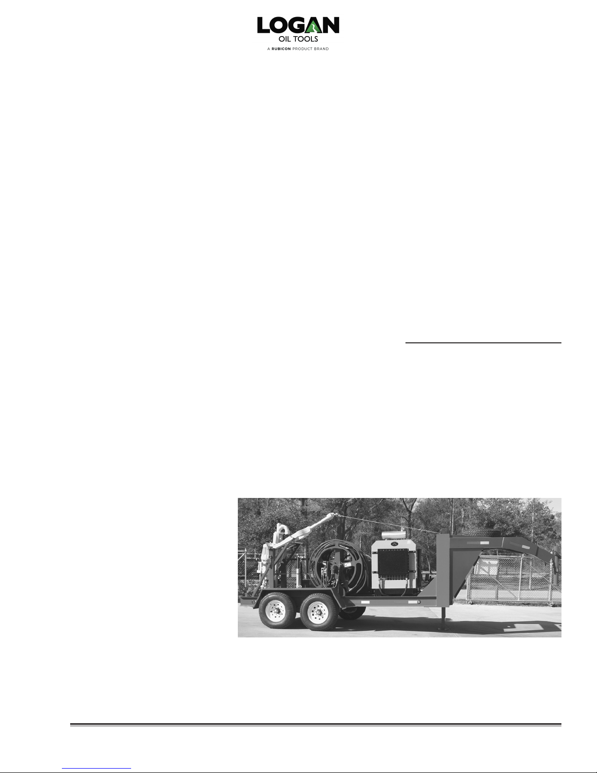
Logan 85-Ton Open Loop Power Swivel
OVERVIEW
The newly engineered, hydraulic motordriven, Logan 85-Ton Open Loop Power
Swivel provides smooth, shock-free
torque. It is rated to support tensile pipe
loads of 85 tons at zero rpm and 45
tons of dynamic load at 100 rpm. The
compact, swivel-head design weighs
only 1,163 lbs and ts into most drilling
or work-over masts.
The design incorporates a reliable,
custom drive train with hardened steel
gears. For most applications, the Logan
85-Ton Open Loop Power Swivel eliminates the use of dangerous spinning
chains, tongs, and kelly spinners. The
Power Swivel facilitates drilling with
longer drill string lengths before the rig
must be shut down to add pipe. Stops
and start-ups are thereby reduced
— improving rig efciency and reducing wear on the pump, drawworks, and
other rig equipment.
The Logan 85-Ton Open Loop Power
Swivel uses an open loop hydraulic
system with variable displacement,
reversible over center pumps, and air or
electric remote controls. Speed control
is continuously variable over the entire
operating range. Pressure compensating-type torque control overrides the
speed control to maintain maximum
torque. The power unit’s torque limits
can be set, thereby eliminating the
potential danger of twist-offs or swollen boxes in the drill string. An integral
rotary swivel bearing, oating washpipe
assembly, and gooseneck connection eliminates the need for a separate
rotary swivel.
A 2-1/2" bore gooseneck and washpipe
assembly allows circulation through the
2" I.D. stem while rotating or in static
mode. An access plug allows wireline
to be run through the unit.
Features include:
•
Smooth, shock-free torque reduces
drill string damage
• Fits most drilling and work over masts
• Allows use of longer drill string lengths
• Power unit torque limits can be set
• Separate rotary swivel is unnecessary
• Choice of diesel engines
• Increased environmental safety
features on skids and trailers
• Easy to service
Extra cost options include:
• Air- or hydro-start engine
• Special hydraulic motor
• Lifting frame
• Electric or hydraulic loading winch
• Dimetcote coating
(inorganic zinc primer)
• Control can be operated remotely
or from the power unit
Cold weather package
•
The complete Logan 85-Ton Open Loop
Power Swivel package includes an
elevator-type bail; a unitized washpipe
packing box assembly; a xed displacement, piston-type, hydraulic motor rated
at 5,000 psi; a torque rein assembly;
safety cable; and 1-inch swivel joints.
The components are available either
trailer- or skid-mounted with powered
hose reels to form a rugged unit. A
swivel carrying stand is standard.
CAUTION:
procedure outlined on page 4 before
installing the Logan 85-Ton Open
Loop Power Swivel on a rig. Failure
to install the Power Swivel properly
can result in injury to the operator
and/or rig floor personnel. Read I portant Safety Information below.
USES
The Logan 85-Ton Open Loop Power
Swivel is ideally suited for use in shing
and workover operations — such as
the internal or external cutting of casing,
tubing, or drill pipe; drilling out plugs,
packers, or cement; milling operations;
or scraping casing — whenever shockfree, controlled torque is essential to
eliminating the potential danger of twistoffs or damage to cutting tools.
The compact, lightweight swivel-head
design also makes it extremely effective
for light to medium drilling applications
including water wells, pilings for piers
and foundations, in addition to oil and
gas wells. Suspending the swivel from
a boom or crane eliminates a great deal
of set-up time or shifts to additional
locations.
The Logan 85-Ton Open Loop Power
Swivel is also ideal for coring operations. Any length of core may be taken.
Accurate and smooth torque ensures
against damage to core tools or strings.
IMPORTANT
SAFETY INFORMATION
Before operating the Logan 85-Ton
Open Loop Power Swivel, users are
advised of the following important safety
precautions and procedures:
1.
Verify the strength of the derrick
structure and torque rein guide cable
to ensure they are strong enough to
withstand the loads imposed by the
Power Swivel.
Refer to the installation
Logan 85-Ton Open Loop Power Swivel • 2

Logan 85-Ton Open Loop Power Swivel
2. A Logan Safety Cable (provided as
standard equipment on the Logan 85Ton Open Loop Power Swivel) should
be used for torque rein and should
be utilized at all times. Attach one
end of the safety cable to the torque
rein and secure the other end to the
swivel. In the event of torque rein
assembly failure, the safety cable will
prevent the assembly from falling to
the rig oor.
3. Carefully check the full range of
travel in the derrick or mast before
beginning operations. With the guide
cable as nearly vertical as possible,
ensure that the swivel can move
freely up and down under full torque
in either direction. Angles exceeding
5% can cause side loads on the
swivel.
4. Although Logan bails are not as
dangerous as “stepped” bails, tubing
elevators should not be used with
Power Swivel bails. Besides being
a potentially dangerous practice, the
use of an upset elevator reduces
the contact between the elevator and
bail, and accelerates wear.
5. Inspect elevators and bails for excessive wear according to guidelines
published in API RP-8B.
WARNING:
Failure to comply with
these safety procedures may cause
physical injury to the operator and/or
rig floor personnel
CONSTRUCTION
Power Swivel Assembly
The Logan 85-Ton Open Loop Power
Swivel is powered by a xed displacement, piston-type, hydraulic motor rated
at 5,000 psi. The motor is mounted
on the underside of the swivel and is
protected by a steel frame.
Lightweight, compact swivel-head design
fits most drilling or workover masts
Two high pressure hydraulic hoses and
the motor drain hose exit from the bottom of the assembly. The high pressure
hydraulic hoses connect to the motor
with swivel joints. The motor drain hose
is tted with a self-sealing quick dis-
connect coupling.
The one-piece gooseneck is construc-
ted of cast steel. A 2-inch I.D. NPT access plug located in the top allows passage of wireline and small tools through
the swivel for downhole operations.
The gooseneck and swivel packing are
hydrostatically tested and rated at 5,000
psi circulating pressure.
The oating washpipe assembly and
packing are self-aligning. Friction bearing surfaces of the washpipe (areas that
contact the packing) are hard-surfaced
for wear-resistance.
The elevator bail is machined or ame
cut from forged, heat-treated alloy
steel for maximum strength. The bail,
bail pins, and body are tested to API
guidelines.
The design incorporates a reliable,
custom drive train with hardened steel
gears consisting of: a motor drive gear,
reduction drive gear, an intermediate
gear, and the main drive gear. Roller
bearings keep the gears in close alignment.
A magnetic drain plug is located on the
lower cover plate of the swivel assembly. A tell-tale hole in the lower plate
indicates hydraulic oil leakage past the
motor shaft seal or lubricating gear oil
past the input pinion shaft. A ller/relief
plug is located on the upper cover plate.
The gear housing is equipped with an
oil level sight glass so the operator may
check oil level with a quick glance.
To protect the main stem oil seal from
dirt, an excluder seal is installed below
the packing nut.
Control Units
Control assemblies for the Logan
85-Ton Open Loop Power Swivel are
either air or electric. They can be operated remotely (extra cost option) for
operator convenience and safety, or
from the power unit. Remote control
assemblies are pedestal mounted. The
control assembly is lightweight and the
pedestal base is removable for easy
storage on the trailer or skid. A new
wireless remote with an operating range
of 150 feet is also available.
Air controls consist of an air compressor
and tank, an air lter/regulator/lubricator
unit, manual torque control, and a pedestal mounted control panel with extra
lines tted with quick disconnect coup-
lers. A lever-operated air valve controls
the engine speed. Another single-lever
air valve controls the direction and
speed of the Power Swivel. A torque
gauge, calibrated in ft-lbs, indicates
torque.
3 • Logan 85-Ton Open Loop Power Swivel
Logan 85-Ton Open Loop Power Swivel
The electric control panel consists of
a joy stick for controlling swivel direction and speed, an engine rpm control
switch, a torque gauge, and a master
kill switch. An emergency kill switch is
available for hazardous locations.
Torque limits can be easily and accurately set on both air and electric control
units. A torque control unit mounted
on the fuel tank can be preset to the
desired torque limit with the turn of
a knob. Torque will be indicated on the
control panel dial in ft-lbs.
Basic Power System
The Logan 85-Ton Open Loop Power
Swivel is equipped with a diesel engine
to pro-vide power. The engine is sized
to provide sufcient horsepower to
operate the swivel to full torque and rpm
limits. Control systems may be either air
or electric.
On units equipped with air control systems, an air compressor rated at 7.4
cfm, a three-gallon receiver tank, and
an air lter-lubricator are also provided.
A torque gauge, calibrated in ft-lbs, is
located on the remote control panel.
Hydraulic System
The hydraulic system includes a direct
driven, variable displacement hydraulic
pump that is mounted directly on the
engine ywheel housing. All piping,
valves, ttings, reservoirs, and other
components required to complete the
system are included. The hydraulic
system is designed and rated at 5,000
psi working pressure.
All hydraulic hoses are reel-mounted
on the power unit. They are connected
to the power swivel hydraulic motor with
swivel joints and quick disconnects.
A swivel carrying rack allows the swivel
to be loaded and unloaded without
breaking the hose connections.
Power Unit
The compact, easily transportable
Power Swivel units may be mounted on
a trailer or skid. All units consist of an
engine with a hydraulic pump, hydrau-
lic piping, a hydraulic uid reservoir, a
hose reel assembly and hoses necessary for supplying hydraulic power to
the power swivel motor. Brackets to
hold and transport the swivel and the
control panel are included.
Trailer-Mounted Unit
The compact, four-wheel trailer units
meet all ICC regulations and are
equipped with heavy-duty springs and
electric brakes. The trailer is equipped
with a gooseneck or bumper pull.
Tongue weight is designed to ensure
on-road stability and eliminate shtailing. Diamond-patterned deck plate
provides solid, skid resistant ooring
over the all welded, steel frame.
Skid-Mounted Unit
Skid units are rugged and made of
heavy-duty structural tubing with welded construction. Both ends are rounded
for easy skidding. Ends are tted with
an integral pipe that may be used to
attach boom lines or hoist slings. These
pipes are ush with the sides of the
skid. Main runners, running the length
of the skid, are strengthened by crossmembers for additional rigidity. The
entire frame is covered with diamondpatterned deck plate to provide a solid,
skid resistant oor.
To meet environmental regulations,
both trailer- and skid-mounted units are
equipped with skirts to eliminate uid
spills.
INSTALLATION
Rig Up
Check all components to ensure that
all accessory items (especially the portable control panel) and spare parts
are packed, and that all equipment is
in serviceable condition. If time permits, the operator should run the power
swivel for a short time to check control
indicators, lter, and response of con-
trols, etc. before leaving for the job site.
The hydraulic reservoir is designed to
dissipate heat and is adequately sized
to disperse foam that may be generated
during operation. A 10-micron suction
lter and high pressure loop lters provide continuous ltration of the hydraulic
uid. Visual registers on the suction
lter and high pressure loop lters indi-
cate when these elements need to be
replaced.
Gooseneck Trailer-Mounted Unit, Side View
Logan 85-Ton Open Loop Power Swivel • 4

Logan 85-Ton Open Loop Power Swivel
Be sure to have an ample supply of fuel
and that the hydraulic reservoir is full.
Upon arriving at the job site, the power
unit should be placed in a level position
a safe distance from the well head and
other hazards. All corners of skid units
should be supported. On trailer units,
wheel chocks should be set in front and
in back of the wheels and the jack lowered to level the trailer bed.
Using a catline or derrick line, lift the
swivel unit from the rack. Suspend
the swivel over the well head from the
drilling hook or elevators. Be sure the
elevator is the correct size for the elevator bail. Carefully inspect the elevator
for excessive wear (refer to API RP-8B
for guidelines).
Remove the control cable or air control
hoses and the pressure gauge hose
from their storage hangers on the skid
or trailer. Connect them to their respective connections on the power unit and
control panel.
Power Swivel Electric Control Panel
Pre-Operation Start-up Procedures
Electric Controls
1.
Move the engine throttle handle to
full “decrease” position.
2. Move the swivel control handle to
neutral position (center).
3. Start the engine:
a. Turn the engine ignition switch
to “on.”
b. Hold the engine throttle control in
“decrease” for 15 to 20 seconds.
c. Hold the engine ignition in “start.”
Release the switch when the en-
gine starts and allow it to return
to the “on” position.
4. Adjust the engine throttle to 800 to
1,000 rpm.
5. Check condition of suction lter. The
lter indicator is located on top of
the hydraulic reservoir. Replace the
lter if the suction gauge reads more
than 5" Hg.
6. Check the suction vacuum gauge
mounted near the pump. It should
not read over 5" Hg.
7. Set the torque control to the desired
maximum torque. The adjustment
knob and torque indicator gauge are
calibrated in ft-lbs. Turn the adjust-
ment knob until the desired maxi mum torque is indicated on the
gauge.
8. Move the swivel control handle
to the “forward” position.
9. Increase engine throttle until the
desired swivel rpm is attained and
the engine runs smoothly.
10. Check the high pressure lter.
Charge pressure should be 100
to 200 psi.
NOTE:
promptly, reset the trip lever on the
air intake manifold located inside
the right-hand engine panel if it has
been tripped.
If the engine fails to start
Air Controls
1.
Move the engine throttle control
lever to neutral position (center).
2. Move the swivel control lever to
neutral position (center).
3. Press and release the start button
on the power unit engine
NOTE:
promptly, reset the trip lever on the
air intake manifold located inside
the right-hand engine panel if it has
been tripped.
If the engine fails to start
4.
Adjust the engine throttle to 800
to 1,000 rpm.
5. Check condition of suction lter.
The lter indicator is located on top
of the hydraulic reservoir. Replace
the lter if the suction gauge reads
more than 5" Hg.
6. Check the suction vacuum gauge
mounted near the pump. It should
not read over 5" Hg.
5 • Logan 85-Ton Open Loop Power Swivel

Logan 85-Ton Open Loop Power Swivel
Power Swivel Air Control Panel
7. Check the air lter/regulator/
lubricator unit. Air pressure should
read 100 psi or more. Lubricator
should be full of oil. Filter should be
free of water. If water is present,
open the drain valve on the bottom
of air reservoir to drain the water.
Close the drain valve.
8. Set the torque control to the desired
maximum torque. The torque control system is mounted adjacent to
the pump. The adjustment knob and
torque indicator gauge are cali-
brated in ft-lbs. Turn the adjustment
knob until the desired maximum
torque is indicated on the gauge.
9. Move the swivel control handle to
the “forward” position.
10. Increase engine throttle until the
desired swivel rpm is attained and
the engine runs smoothly.
11. Check the high pressure lter.
Charge pressure should be 100 to
200 psi.
The Logan 85-Ton Open Loop Power
Swivel is now ready for operation.
OPERATION
General Rules
Logan Oil Tools recommends the following rules be observed when operating
the Power Swivel. These operational
rules apply to all power swivel units,
whether they are equipped with air or
electric controls.
1.
The pump displacement control
should always be used to change
the speed of the swivel. Setting the
engine at the rated rpm will prolong
engine and pump life, burn less oil,
and result in fuel economy.
2. Set the speed control at minimum
and allow the engine to idle before
changing the direction of rotation.
Allow the swivel to completely stop in
neutral before switching to reverse.
3. Filters should be checked on a daily
basis.
4. The hydraulic uid level should be
checked weekly. If the level is below
the sight gauge, add hydraulic uid.
5. Charge pressure and suction gauges
should be monitored daily.
NOTE:
Fluid (Part No. 06206) or approved
equivalent when adding or changing
hydraulic fluid.
Air Controls
The air control system utilizes a single
lever-type control valve that is mounted
on the remote control panel. This control provides variable air pressure from
0 to 100 psi to the actuator positioner
to control both engine speed and the
direction of swivel rotation.
When this lever is in the center position,
the pump is in neutral and the Power
Swivel is not rotating.
Electric Controls
Diesel engine speed is controlled by
the lever labeled “Engine Throttle” on
the control panel.
Swivel rotation is controlled by the lever
labeled “Swivel Control.” It utilizes a
forward/neutral/reverse switch to control
rotation direction. Moving the lever to
the “forward” position will cause the
Power Swivel to move in a right-hand
(clockwise) direction.
Push the “Engine Throttle” lever forward
until the desired speed is attained.
Increase the engine speed if the engine
begins to overload or if a higher swivel
rpm is required.
Pressure compensating-type torque
control overrides the speed control to
automatically maintain the maximum
pre-established torque limit. This is
accomplished by reducing the pump
stroke while maintaining engine speed.
If the engine speed continues to be
overridden, the engine speed should be
reduced until identical torque and speed
conditions exist at full pump stroke.
Use only Logan Hydraulic
6. Do not permit hydraulic oil temperature to exceed 190°F for extended
periods.
Logan 85-Ton Open Loop Power Swivel • 6

Logan 85-Ton Open Loop Power Swivel
MAINTENANCE
The following guidelines are intended
to ensure maximum life of the Logan
85-Ton Open Loop Power Swivel.
These are recommendations only.
Extreme peak load usage, temperature,
and other variables will affect suggested
service intervals.
Power Swivel Maintenance
Lubrication
1.
Check the gear lubricating oil prior
to service. The oil level should be
maintained at the oil level plug level
at all times. If necessary, bring oil to
the proper operating level by adding
Logan Gear Lubricant (Part No.
G14085-001). Some lubricating oil
may leak out when the oil level plug
near the top cover plate is removed.
If oil does not leak out, gear lubricating oil of proper type and grade
should be added to the correct operating level.
2. Gear lubricating oil should be
changed after the rst 100 hours of
initial operation. Check the magnetic
drain plug for metal lings when
changing the gear lubricating oil.
NOTE:
Ton Power Swivel is eight (8) quarts.
3. After the initial break-in period (rst
4. Regularly subject the elevator bail,
Oil capacity of the Logan 85-
100 hours of operation), the gear
lubricating oil should be changed
after each 1,000 hours of operation
thereafter, or if the unit has been out
of service for an extended period.
Always check the magnetic drain
plug for metal lings when changing
the gear lubricating oil.
stem, and saver subs to magnetic
particle inspection.
Breaking-In
During initial break-in, or after a long
period of idleness, run the Power Swivel
with a reduced load at slower speed
until it reaches normal operating temperature ranging between 120 – 200°F.
A somewhat higher operating temperature is permissible in very hot climates,
provided that it increases gradually.
Storage
If the Logan 85-Ton Open Loop Power
Swivel must be stored, it should be
completely lled with gear lubricating oil
to prevent oxi-dation. Thread protectors
or lift plugs should be installed on stems
or saver subs to prevent damage to the
threads. Grease or dope the threads
before installing the thread protectors or
lift plugs.
Open gear housings, ports, and removed motors should be covered with
clean drop cloths to prevent dirt and
trash from entering internal mechanisms. Before shipping parts for service,
all openings should be sealed and parts
wrapped in clean, heavy kraft paper.
Replacing the Floating Washpipe
Assembly and Packing
The entire Floating Washpipe Assembly,
including the upper and lower packing
nuts, can be removed from the swivel
without removing the gooseneck or
bonnet.
Remove the four retainers and retaining screws from the lower packing nut.
Loosen the lower packing nut by turning
it in a clockwise direction until it turns
freely. Secure the upper stem to keep
it from rotating while loosening and
removing the lower packing nut. Use
the same procedure to loosen and
remove the upper packing nut from the
gooseneck.
Remove the washpipe and packing
assemblies. Press the washpipe out
of the lower packing nut and slide the
upper nut off. Remove the three upper
packing locking pins and press the upper packing off the washpipe. Replace
the washpipe if it shows any signs of
wear (i.e., scoring or surface abrasion).
The average life expectancy of the
packing is 200 – 250 hours. Remove
the old packing from the packing nuts.
Thoroughly clean the inside of both
nuts. Using the drawing on page 8 as
a reference, install the new packing.
Assemble the packing and oating
washpipe assembly in reverse of assembly procedure. Tighten the packing
nuts securely, locking them in place with
the retaining screws and retainers.
Power Unit Maintenance
The Power Unit includes the engine,
piping, lters, reservoir, hoses, hose
reels, cables, electrical components,
and gauges.
Engine
Please refer to the specic engine man-
ufacturer’s maintenance instructions
included with your documentation.
Hydraulic Oil and Filters
The hydraulic uid reservoir (Logan
Part No. PS06206) should be maintained at the proper level at all times.
The oil level should be visible in the
sight gauge when cold.
Filters
The return lter located at the top of the
reservoir should be replaced when the
pointer indicates that it needs cleaning.
The indicator registers when the engine
is running.
The high pressure lter in the pressure line should be serviced when the
condition indicator displays red. Green
indicates that the lter is in satisfactory
condition. The lter indicator operates
when the swivel is rotating to the right.
7 • Logan 85-Ton Open Loop Power Swivel

Floating Washpipe Assembly
Gooseneck Pipe
PS77322
2" NPT
1
3
2
4
5
6
7
Plug
2-1/2 API
LINE PIPE
15
16
8
9
10
11
12
1413
Body
PS54075
FLOATING WAShPIPE ASSEMbLY (PS49028-001) REPLACEMENT PARTS
Item Logan Part no. Qty DescrIPtIon
1 PS09028 1 Gooseneck
2 ACSA8-500-13-150 4 1/2"
- 13 x 1-1/2" Socket Head Cap Screw
3 LKWA-500 4 1/2" Lock Washer
4 PS19028 1 Bonnet
5 568-236 2 O-Ring
6 PS79028 1 Upper Packing Nut Ring
7 PS50732-003 8 1/2" - 13 NC x 3/4 Socket Set Screw
8 PS20128 8 Washpipe Packing Nut Screw Retainer
9 PS99028 3 Washpipe Locking Pin
10 568-010 3 O-Ring
Item Logan Part no. Qty DescrIPtIon
11 PS72327 1 Packing Set
12 PS39028 1 Upper Packing Nut
13 ACSA8-625-13-150 4 5/8" - 13 x 1-1/2" Socket Head Cap Screw
14 LKWA-625 4 5/8" Lock Washer
15 PS49028 1 Washpipe
16 PS69028 1 Spacer
17 PS63672 1 Packing Nut Grease Fitting
18 PS62327 1 Plain Spacer Ring
19 PS42327 1 Packing Bottom Ring
20 PS29028 1 Lower Packing Nut
17
18
11
19
8
7
20
5
and Lantern Ring
Logan 85-Ton Open Loop Power Swivel • 8

Logan 85-Ton Open Loop Power Swivel
Hoses
Lubricate the hose reel swivel joints
with automotive chassis grease
monthly.
Inspect the torque control mechanism
every six months and coat all moving
parts with automotive chassis grease.
Avoid contaminating the hydraulic uid
and hydraulic system, including the
hoses and couplings, with dust, water,
or other foreign matter. Introduction of
foreign materials into the system will
damage the machinery.
Torque gauge hose end connections should be kept clean at all times
through the use of dust covers or by
wrapping them with a clean cloth when
not in use. Open, loose ends, especially
those that have been dropped on the
ground, should be thoroughly cleaned
inside and out, and ushed prior to use.
Extend the life of the hoses by never
allowing them to become twisted or
kinked, or unnecessarily stretched. Do
not allow any sharp or heavy objects
to drop or lay on the hoses. Doing so
may cut or crush them.
Thoroughly clean the power unit when
the job has been completed. Replenish
the engine fuel and hydraulic oil supplies. Make any necessary repairs at
this time. Hoses should be reeled after
cleaning and the hose ends covered.
Power Units with Air Controls
Expel water condensate from the tank
daily by opening the drain valve on the
bottom of the air receiver. Pressurize
the tank before opening the valve.
Visually inspect the lter/lubricator valve
twice a day. Drain any water that has
collected in the lter bowl and maintain
the lubricating oil at the proper operating level with SAE 10W motor oil.
Always keep the pump stroke cylinder
rod, rod bearing, and clevis coated with
chassis grease.
Power Units with Electric Controls
The electrical cable should be coiled
and stored on the cable bracket when
not in use. Cover the open end with
the provided dust cap. Avoid kinking
or placing undue tension on the cable.
Do not allow equipment to run over the
cable.
Open the relay cabinet at least once
a year (more often in humid climates)
for cleaning. All exposed terminals and
metal parts should be cleaned, dried,
and sprayed with silicone or varnish.
Power Swivel
Power Swivels should not be started
or operated in freezing weather until
the hydraulic system has been properly
prepared for cold weather service by:
1.
Charge the hydraulic system with
hydraulic oil rated for cold weather.
2. Prepare the engine according to the
manufacturer's recommendations.
3. Ensure the hydraulic system is
moisture-free.
Never allow the power unit to vibrate.
Vibration indicates mechanical misalignment or that the unit is not properly supported. The power unit should
be shutdown until the cause can be
determined and eliminated. Continued
excessive vibration will cause severe
damage to the hydraulic pump and
other components.
Machinery and hoses should not be
allowed to remain outdoors when not
in use.
In cold climates, it is particularly important to keep the hydraulic system free
of moisture caused by condensation or
water contaminated hydraulic uid. Any
moisture in the system may freeze and
cause severe damage, especially to the
pump and valves.
Power Unit
Inspect trailer-mounted units prior to
use to ensure that it is safe and roadworthy. Pay particular attention when
inspecting the following items:
1. Trailer hitch and safety chain
2. Brakes and tires
3. Tail and brake lights, and turn signals
4. Reserve fuel supply
5. Trailer tongue jack and supports
9 • Logan 85-Ton Open Loop Power Swivel
Gooseneck Trailer-Mounted Unit, Rear View

Logan 85-Ton Open Loop Power Swivel
SWIVEL DISASSEMbLY
Care should be taken to ensure that
no foreign material enters the interior
machinery of the swivel. All disassembly
and major repairs should be conducted
in a clean, well-equipped shop.
1. Remove all hydraulic hoses from the
swivel. Hose ends should be covered
to help prevent foreign matter from
entering the interior.
NOTE:
lic hoses should be reeled up to
prevent kinking and other damage.
Damaged hoses may cause blockage
or other interference that the unit
may not function properly.
2. Place the swivel on a suitable rack
3. Remove the hydraulic motor guard.
4. Place an open container under the
5. Remove the four retaining screws
6. Press the washpipe out of the lower
When not in use, all hydrau-
(similar to the bracket on the skid or
trailer) that supports the swivel on its
bail pins.
magnetic drain plug and remove
the plug. Check the drain plug and
drained hydraulic uid for metal lings
and other foreign matter.
and their retainers from the lower
packing nut. Secure the lower stem
of the swivel to keep the upper stem
from turning while loosening the lower
packing nut. Turn the lower packing
nut in a clockwise direction until it
turns freely. Back the lower packing
nut completely off the upper stem.
Repeat the above procedure to
remove the upper packing nut and
back it completely off the gooseneck.
Remove the oating washpipe and
packing assembly.
packing nut and slide the upper nut
off. Remove the three upper packing
locking pins and press the upper
packing off the washpipe. Replace
the washpipe if it shows any signs of
wear (scoring or surface abrasion).
7. Remove the packing assembly parts
from inside both nuts. (The lower
packing assembly consists of an
o-ring, packing bottom ring, plain
spacer ring, spacer and lantern ring,
and three packing rings. The upper
packing assembly consists of an
o-ring, upper packing nut ring, and
one packing ring.) When replacing
the packing, it is important that both
packing nuts are clean and free of all
old packing residue. Make sure both
packing nuts are clean and free of
foreign matter.
8. Remove and set aside the goose
neck and bonnet.
9. Turn the swivel upside down. Remove the hydraulic motor and set it
aside.
NOTE:
draulic motor. If trouble with the motor is known or suspected, carefully
plug the ports and return the motor
to Logan Oil Tools for inspection and
repair.
10. Remove the piping that runs from
11.Remove the lower bearing retainer
12. Remove the seal retainer snap ring
13. Turn the swivel upright and remove
14. Remove the cap screws from the
15. Remove the upper gear cover shim
Do not disassemble the hy-
the oil ller plug opening in the top
plate to the side of the swivel body
next to the rst reduction gear.
screws. Set the retainer aside and
remove the gasket.
from the bearing retainer and the
two lower oil seals.
the upper seal protector from the top
of the stem.
top cover plate. A rubber mallet may
be used to break the gasket seal
if necessary. Lift off the top cover
plate.
and gasket. A putty knife or other
thin tool may be used for prying and
cleaning.
16. Remove the oil seal from the upper
cover plate. Using the inside bearing
puller, pull the outer track of the
stem upper bearing from the top
cover plate. This will free the stem
for removal.
17. The inner tracks of the stem’s upper
and lower bearings and seal wear
ring at the bottom of the stem may
be removed with a bearing puller.
The nal reduction gear is removed
by rst removing the six ring groove
pins and then forcing the gear off the
main stem.
18. Remove the screws from the lower
gear cover plate. Tap the cover plate
gently with a rubber mallet to break
the seal if necessary. Scrape off
remaining residue with a putty knife.
19. Remove the rst reduction pinion
bearing spacer and the rst reduc-
tion pinion lower bearing from the
swivel body.
20. Lift out the nal reduction pinion,
main thrust bearing, second reduc-
tion pinion, and rst reduction
pinion. The gears may require
rotation to facilitate removal.
21. Remove the remaining roller bearings, second reduction lower bear-
ing with its retainer ring, and rst
reduction pinion upper bearing. As
with all bearings, exercise caution
when handling to guard against
possible damage.
NOTE:
oughly cleaned (with steam or a high
pressure washer for metal parts, or
with a good grade solvent applied
with a clean brush) as it is removed.
Check parts for repair or replacement as they are cleaned. Dry all
cleaned parts with compressed air
or a clean, soft cloth. Coat all clean,
dry parts with a thin coat of lubricating oil. Never leave parts exposed
overnight without a coating of protective oil.
Each part should be thor-
Logan 85-Ton Open Loop Power Swivel • 10

Swivel head Parts List
Item numbers refer to drawing callouts on pages 12 – 15
Item Part no. Qty. DescrIPtIon
1 PS09028 1 Gooseneck
2 ACSA8-500-13-150 14
3 LKWA-500 16 1/2" Lockwasher
4 PS19028 1 Bonnet
5 568236 2 O-Ring
6 PS79028 1 Upper Packing Nut Ring
7 PS50732-003 8 1/2" - 13 NC x 3/4" Long, Socket Set Screw
8 PS20128 8 Washpipe Packing Nut Screw Retainer
9 PS99028 3 Washpipe Locking Pin with 56810 O-Ring
10 568010 3 O-Ring
11 PS72327 1 Set Packing
12 PS39028 1 Upper Packing Nut
13 ACSA8-625-13-150 4
14 LKWA-625 4 5/8" Lockwasher
15 PS49028 1 Washpipe
16 PS69028 1 Spacer and Lantern Ring
17 PS63672 1 Packing Nut Grease Fitting
18 PS62327 1 Plain Spacer Ring
19 PS42327 1 Packing Bottom Ring
20 PS29028 1 Lower Packing Nut
21 HCSA8-625-13-150 9 5/8" - 13 x 1-1/2" Long, Hex Head Cap Screw
22 PS44322 2 Dowel Pin
23 AHSS-625-11-625 4 5/8" - 11 x 5/8" Long, Allen Head Set Screw
24 PS77122 1 Filler Plug Relief Fitting
25 PS98352 1 Oil Filler Plug
26 PS72602 1 Magnetic Drain Plug
30 PS78103 1 1" Wing Nut Quick Disconnect
31 PS22196 1 1-1/4" Quick Disconnect Set
33 PS55164 1 Lower Bearing Retainer Gasket
34 HCSA8-625-11-175 6 5/8" - 11 x 1-3/4" Long, Hex Head Cap Screw
35 PS50602 1 Saver Sub
36 HCSA8-500-13-150 4 1/2" - 13 x 1-1/2" Long, Hex Head Cap Screw
37 PS91764 4 1/2" Special Flat Washer
38 PS93456 2 1-1/4" Swivel Joint
39 PS55115-003 1 Shackle
40 PS55115-003 1 Torque Rein Assembly
41 PS697702 1 Torque Rein Eye
42 PS21415 1 Torque Rein Pull Pin
43 PS91875 1 Upper Gear Cover Shim
44 PS85-OL-KM40.109 1 Hydraulic Motor (Open Loop Gear)
45 PS65895-OL 2 Hydraulic Motor Manifold Assembly
47 ACSA8-375-13-275 8
48 LKWA-375 8 3/8" Lockwasher
1/2" - 13 x 1-1/2" Long, Socket Head Cap Screw
with Brass Point
5/8" - 11 x 1-1/2" Long, Socket Head Cap Screw
3/8" - 13 x 2-3/4" Long, Socket Head Cap Screw
Item Part no. Qty. DescrIPtIon
49 PS77322 1 Gooseneck Pipe Plug
50 PS20213 1 Elevator Bail
51 PS28444 1 Seal Protector
52 PS34813-001 1 Bolt and Nut for Bail Pin
53 PS65115 1 Bail Pin
54 PS12965 1 Final Reduction Gear
55 PS64702 6 Ring Gear Groove Pin
56 PS98402 1 Main Thrust Bearing
57 PS04685 1 Lower Stem Bearing Spacer
58 PS70602 1 Lower Stem Bearing
59 PS54075 1 Body
60 PS14685 1 Lower Stem Bearing Retainer
61 PS22602 2 Lower Oil Seal
62 PS16303 1 Seal Retainer Snap Ring
63 PS51602 1 Lower Seal Wear Ring
64 PS18444-001 1 Stem
65 PS64165 1 Second Reduction Pinion
66 PS05775 1 Second Reduction Gear Key
67 PS15165 1 First Reduction Pinion Upper Bearing
68 PS37965 1 First Reduction Pinion Upper Gear
69 PS05165 1 First Reduction Pinion Lower Bearing
70 PS44685 1 First Reduction Pinion Bearing Spacer
71 PS12685 1 Lower Gear Cover Gasket
72 PS25165 1 First Reduction Pinion Oil Seal
73 PS62516 1 Hydraulic Motor Adapter
74 PS08327 1 Retainer Ring
75 PS97327 1 Motor Adapter Sleeve
76 PS45165 1 Retainer Ring
77 PS85152 1 Second Reduction Shaft Lower Bearing
78 PS65165 1 Reduction Gear Key
79 PS95675 1 Lower Gear Cover Plate
80 PS27965 1 First Reduction Gear
81 PS84165 3 Roller Bearing
82 PS55935 1 Oil Seal Grease Fitting
83 PS90137 1 Oil Level Indicator Plug
84 PS88402 1 Upper Stem Bearing
85 PS02685 1 Upper Oil Seal
86 PS12165 1 Second Reduction Gear
87 PS53775 1 Upper Gear Cover Plate
88 PS03165 1 Final Reduction Pinion
89 PS95516-001 1 Motor Guard
90 PSWB3 3 Hose Safety Cable
91 G14085-001 2.5 Gal HD-85W-140 Gear Lube
11 • Logan 85-Ton Open Loop Power Swivel
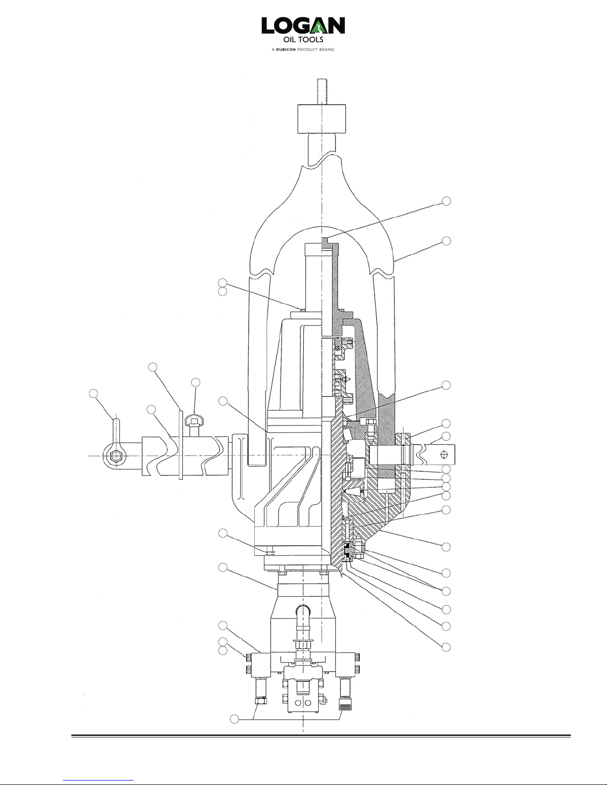
Swivel head – Front View
Refer to Parts List on page 11 for part numbers and descriptions
49
50
2
3
41
42
39
40
43
2
44
45
47
48
51
52
53
54
55
56
57
58
59
60
61
62
63
64
31
Logan 85-Ton Open Loop Power Swivel • 12

Swivel head – Side View
Refer to Parts List on page 11 for part numbers and descriptions
24
25
33
26
3 13
36 14
37
30
38
2
3
13
34
64
35
13 • Logan 85-Ton Open Loop Power Swivel

(See page 15 for Section A-A)
A
Swivel head – Top View
Refer to Parts List on page 11 for part numbers and descriptions
13 14
A
(See page 15 for Section A-A)
24 25
13 21
22
23
Logan 85-Ton Open Loop Power Swivel • 14

Section A-A – Through Gear Train
Refer to Parts List on page 11 for part numbers and descriptions
23
85
84
83
64
33
86 87
88 81
43
65
66
67
68
69
70
82
80
81
78
79
76
77
75
74
73
71
72
15 • Logan 85-Ton Open Loop Power Swivel

Logan 85-Ton Open Loop Power Swivel
22. Remove the bail only when absolutely necessary. Lay the bail and
swivel body down so the holes at
the bottom of the bail pockets in the
body can be reached. Set a 10inch-long dowel rod with a diameter
slightly smaller than the bail pocket
holes against the pin. Strike the
dowel with a hammer. Once the
grooved pin has been removed,
insert a rod in the pull pin hole. Use
a rubber mallet to loosen the bail
pin by tapping it in alternate direc-
tions. Pour penetrating oil around
the pin to aid the loosening process.
While pulling on the pin, repeat the
loosening process until the pin is
removed. Lift out the bail.
NOTE:
tors, hoses, or similar items are to be
stored or shipped for repair, all ports
and openings should be carefully
sealed to prevent foreign matter from
entering interior parts.
SWIVEL REASSEM
Care should be taken to ensure that
no foreign material enters the interior machinery of the swivel.
repairs and reassembly should be conducted in a clean, well-equipped shop.
In the event hydraulic motors, hoses, or
similar items are to be stored or shipped
for repair, all ports and openings should
be carefully sealed to prevent foreign
matter from entering.
NOTE:
ly cleaned, dried, oiled, and in good
operating condition. Never reuse the
gear lubricating oil drained from the
swivel. Always use new, fresh oil of
the recommended type and grade.
O-rings should never be reused. It is
also recommended that all oil seals
be replaced.
In the event hydraulic mo-
bLY
All major
All parts should be thorough-
1. Place the swivel on a suitable rack
(similar to the bracket on the skid
or trailer) that supports the swivel
on its bail pins.
2. Install component parts on the
stem:
a. Press nal reduction gear back
on the stem and install groove
pin.
b. Press on upper stem bearing.
c. Install main thrust bearing.
d. Install stem lower bearing spacer.
e. Press on lower stem bearing
inner race.
f. Press on lower seal wear ring.
3. Install component parts onto shafts:
a. Install key and second reduction
gear onto nal reduction pinion.
b. Press roller bearings onto each
end of nal reduction pinion.
c. Press roller bearing on upper end
of second reduction pinion.
d. Press rst reduction pinion lower
bearing onto rst reduction
pinion.
4. With the stem lower bearing in
place, set the main stem through
the stem lower bearing into position
in the body.
5. Check the top face of the body,
making sure that the surface is
clean and free of burrs. Place a
gasket on the face of the body.
6. Place a set of three shims (one
each in thicknesses of .005", .007",
and .020") on the body face.
7. With the upper cover plate upright,
press the upper oil seal into position. Press the outer race of the
stem upper bearing into the top
cover plate.
8. Position the upper cover plate over
the stem and into place on the
body. Insert cap screws with lock
washers into the upper plate and
tighten.
9. Place a small hydraulic jack under
the lower end of the stem and a
micrometer against the top of the
stem to detect and measure any
vertical movement (end-play). Apply
lift to the stem with the jack and
note any movement shown on the
micrometer.
10. Remove the jack, micrometer, and
the top cover plate. Remove the
shims and replace them with a
combination of shims that will allow
a sufcient total amount of end-play
between .004" and .005".
NOTE:
plate without sufficient shims or
over-tighten the upper plate cover
screws. Doing so will cause the bearings to bind.
1
12. Set the rst reduction pinion, rst
13. Remove the top cover plate and
14. Turn the swivel upside down. Check
Do not tighten the cover
1. Press the second reduction pinion
lower bearing into the lower cover
plate. Set the retainer ring into position above the bearing and press
the rst pinion upper bearing into
place in the body.
reduction gear, and rst reduction
pinion bearing spacer into place in
the swivel body.
set the nal and second reduction
pinion into place. Rotate the shafts
in order to mesh the gears. Reinstall the top cover plate and tighten
the screws.
the bottom surface of the body for
burrs and atness. Lay the lower
cover gasket on the face. Position
the lower cover plate on the body
and insert the cap screws with lock
washers. Tighten the screws.
Logan 85-Ton Open Loop Power Swivel • 16

Logan 85-Ton Open Loop Power Swivel
15. Place the two lower stem oil seals
into position on the stem’s lower
bearing retainer. Set the seal retainer snap ring on the bearing retainer.
When properly assembled, the lips
of the oil seals should point upward.
Exercise caution when assembling
the oil seals over the wear ring,
being careful not to tear or turn
back the lips of the oil seals or
cause other damage to the seals.
Dam
aged seals will cause leakage.
Set the lower bearing retainer over
the stem and in place on the body.
Insert the six lower bearing retainer
cap screws with lock washers.
Tighten the screws.
16. Insert the rst reduction pinion oil
seal. Place the hydraulic motor
with the hydraulic motor adapter
attached into position. Insert the
eight cap screws with lock washers.
Tighten the screws. Attach the
hydraulic motor guard.
17. Turn the body upright.
18. Grease the upper oil seal and place
the upper seal protector in position
on the stem. Make sure the seal
protector is right-side up with the lip
against the upper cover plate.
19. Assemble the bonnet to the upper
cover plate and bolt the gooseneck
to the bonnet. Insert the gooseneck
pipe plug and tighten.
20. Coat the packing elements (o-rings,
upper packing nut ring, packing,
spacer and lantern ring, plain
spacer ring, and packing bottom
ring) generously with Logan packing
lubricant and install them into their
respective packing nuts. Reassem-
ble the oating washpipe assembly
and packing in reverse of the dis-
assembly procedure outlined on
page 7. Reinstall the packing nuts,
retainers, and retainer screws, tight ening and locking the packing nuts
securely.
Securely tighten the packing nuts
and lock into place with their re
spective retainers and retainer
screws.
21. Lay the unit at on a workbench
and insert the bail into the bail
pockets of the body. Align the bail
pins with the lock pin holes in the
body. Secure the bail by driving
the bails pins into place with a rubber mallet. As the lock pins come
into alignment, drop a drift punch
through them, driving lightly to
laterally align them.
22. Drop the bail pin grooves into place
and snug-up with a hammer. Hang
up the swivel by the bail and support the underside of the swivel.
Using a medium weight (2-1/2 lbs)
sledge hammer, drive the pins in
straight through until the heads are
ush with the top of the bail pock-
ets.
17 • Logan 85-Ton Open Loop Power Swivel
23. Reattach all piping to the hydraulic
motors before reattaching the motor
guard.

Logan 85-Ton Open Loop Power Swivel
TROUbLEShOOTING
GENERAL
Loss of charge pressure — Charge pressure gauge registers zero. Gauge may be defective. Remove charge
pump in neutral. pump and inspect for broken parts.
Loss of charge pressure — Vacuum gauge reading is high Suction strainer may be clogged.
pump in neutral. (10" Hg or more). Replace lter.
Loss of charge pressure — Charge pressure is less than 60 psi when Pump or motor may be defective. Close
pump on stroke. power swivel is rotating at full rpm. the ball valve in the high pressure line.
Put pump stroke on stroke. If charge pressure is normal, the motor is defective.
Replace valve and bearing plates.
If charge pressure is not normal, the pump
is defective. Replace valve and bearing
plates in the pump.
Hydraulic oil overheats Temperature gauge registers 190°F Hydraulic oil has been aerated (a milky ap-
or higher. pearance indicates presence of air in the oil).
Check suction connections on charge pump.
Check oil level in reservoir.
AIR CONTROL SYSTEM
Unable to control speed Power Swivel has low rpm Low air pressure.
Adjust air pressure to 100 psi.
Sticky air cylinder.
Clean and lubricate air cylinder on pump.
Defective air control valve.
Replace valve section of pump control.
Swivel rotates when control is Visual Air cylinder rod is out of adjustment.
in neutral position (air controls) Remove bolt and allow rod to center.
Adjust rod end to match.
ELECTRIC CONTROL SYSTEM
Loss of speed control Visual Defective rheostat. Voltage to control valve
should be zero to 9 volts DC. Replace con
trol valve if defective.
Dirty or defective control valve. Free the
sticky spool by rapidly moving the lever on
the valve back and forth.
Loose electrical connection at control valve
or pressure safety switch. Clean and tighten
connections.
Loss of direction control Visual Defective forward/reverse switch. If no volt-
age to pump control valve. Replace with new
switch.
Swivel rotates when control Visual Control valve on pump is not properly cen-
is in neutral position (electric controls) tered. Loosen lock nut on hex bolt located on
the front of the control. Turn bolt in one direction until the swivel turns. Turn the bolt in the
opposite direction, counting the turns until
the swivel turns in the opposite direction.
Turn the bolt to midpoint and fasten the lock
nut.
Displacement control adjustment is not
centered. Consult hydro-transmission
manual.
Logan 85-Ton Open Loop Power Swivel • 18

Specications
POWER SWIVEL SPECIFICATIONS
MODEL NO. PS85-OL
NOMINAL LOAD RATING (tons) 85
DYNAMIC LOAD RATING @ 100 RPM (tons) 45
MAXIMUM TORQUE (ft-lbs) 3,356
MAXIMUM SPEED (rpm) 150
MAXIMUM CIRCULATING PRESSURE 5,000
STANDARD STEM CONNECTION 2-7/8 IF
GOOSENECK CONNECTION 2-1/2 NPT
SWIVEL HEAD ASSEMBLY WEIGHT (lbs) 1,163
POWER UNIT & CONTROL SPECIFICATIONS
MODEL NO. PS85-OL
DIESEL ENGINE * 4BTA
ENGINE CONT HP @ 2000 RPM 83
HYDRAULIC OUTPUT (max gpm/max psi) 60.7/3,000
* Choice of Cummins, Caterpillar/Perkins, or John Deere
CAUTION:
Before installing a Logan 85-Ton Open Loop Power Swivel on a rig,
refer to the installation procedure on page 4. Failure to install the Power Swivel
properly can result in injury to the operator and rig floor personnel
19 • Logan 85-Ton Open Loop Power Swivel

2" NPT PLUG
Swivel head – Dimensions
5
Ø
2-7/8
Ø
20-17/32
18-1/2
16-5/32
2-7/8 API IF
4-1/32
23-5/32
20-15/16
53-15/16
32-7/16
2-1/2 API
LINE PIPE
13-23/32
19-1/2
41-7/32 CLOSED
58-17/32 OPEN
Logan 85-Ton Open Loop Power Swivel • 20

Power Unit Parts List
PS85-OL POWER UNIT PARTS LIST
LOGAN PART NO. QTY DESCRIPTION
PS911712 1 14 ft Gooseneck Trailer
PS811712 1 14 ft Bumper Pull Trailer
PS81795 1 14 ft Skid
ENGINES
PS290412-007 1 Cummins T-II with Compressor
PS290413-003 1 Caterpillar T-II with Compressor
PS290414-001 1 John Deere T-II with Compressor
PS290412-001 1 Perkins T-II with Compressor
PS290412-005 1 Cummins T-II without Compressor
PS290414-002 1 John Deere T-II without Compressor
PS290412-005 1 Perkins T-II without Compressor
HYDRAULIC PUMP
PS85-OL-KP40/KP20 1 Hydraulic Pump for Air Controls
PS85-OL-Main Valve 1 Control Valve
PS255002 1 Pump Motor Adapter
HYDRAULIC RESERVOIR
PS89046-OL-Assy. 1 125 gal Hydraulic Tank Reservoir
Consisting of:
PS780412 1 Hydraulic Suction Strainer
PS754T08N 1 Hydraulic Suction 2" Ball Valve
PS099612 1 Hydraulic Return Filter Assembly
PS099612-001 1 Hydraulic Return Filter Element Only
PS80602 1 Hydraulic Vacuum Gauge
PS02311 1 Filler Breather Cap
PS30795-002 1 Oil Level Gauge with Temperature
PS89046-OL 1 Hydraulic Reservoir Only
PS233612 1 Relief Back Pressure Orice
FUEL TANK
PS96892-001 1 60 gal Fuel Tank Assembly
Consisting of:
PS96892 1 Fuel Tank Only
PS96892-2 2 Fuel Sight Tube
PS94626 1 1-1/4" High Pressure Ball Valve
PS61648 2 High Pressure Filter Assemblies
Consisting of:
PS921512-001 2 High Pressure Filter Element Lng
PS921412-002 2 High Pressure Filter Housing
PS921412-003 2 High Pressure Filter Head
PS02311 1 Filler Breather Cap
PS811412 1 Fuel Suction Tube
PS811412-A 1 Fuel Return Tube
PS96892 1 Fuel Tank Weldment
MISCELLANEOUS
PSMM9000-002 1 Electric Winch
PS558612-001 1 Hydraulic Winch
PSBattery Box 1 Battery Box
PSTool Box 1 Tool Box
PS211412 1 Power Swivel Stand
LOGAN PART NO. QTY DESCRIPTION
HOSE REEL
PS670712-OL 1 Hose Reel Assembly with Hydraulic Winch
PS97556 1 100 ft High Pressure Hose Assembly
PS24376 1 100 ft, 3/4" Case Drain Hose
PS195412 1 Hydraulic Valve for Reel
PS85-OL-HR/HW Valve 1 Hydraulic Valve for Reel with Hydraulic Winch
PS220712 1 Hydraulic Motor Hose Reel
PS89638-002 1 Flow Control Hose Reel
PS490412 1 Three-Port Coupling Hub
PS120712 1 Torque Hub
AIR TORQUE SET PANEL
PS223612-OL 1 Torque Set Panel Assembly
PS22236-OL 1 0 – 3,356 ft/lbs Torque Gauge
PS98126 1 Torque Set Relief Valve
PS220512 1 Torque Set Air Override Valve
AIR CONTROL PANEL
PS09966-003 1 Pump Control Valve
PS29966 1 Engine Throttle Control Valve
PS22236-OL 1 0 – 3,356 ft/lbs Torque Gauge
PS220512 1 Engine Kill Valve
PS80345-003 5 1/4" Quick Disconnect, Air Male x Male Pipe
PS70345 1 1/4" Quick Disconnect, Hydraulic Male x Male Pipe
PS217752 1 Control Umbilical Bundle
PS70345-001 5 1/4" Quick Disconnect, Air Female
PS80345-003 1 1/4" Quick Disconnect, Hydraulic Female
AIR PREPARATION PACKAGE
PS81455-002 1 Air Preparation Package
PS81455 1 3 Gallon Air Receiver
PS24695 1 Gauge
PS73585 1 Safety Pop-Off Valve
PS93646-001 1 Filter Regulator/Lubricator
PS81455-003 1 Tank Guard
PS57196-OL 1 Heat Exchanger
FILTERS
PS290412-009A 1 Cummins Oil Filter
PS290412-009B 1 Cummins Fuel Filter
PSAF1640 1 Cummins Primary Air Filter
PSAF1641 1 Cummins Secondary Air Filter
PS2654407 1 Caterpillar Oil Filter
PS26560201 1 Caterpillar Fuel Filter
PS26510380 1 Caterpillar Primary Air Filter
PS26510381 1 Caterpillar Secondary Air Filter
PSP550779 1 John Deere Oil Filter
PSP550759 1 John Deere Fuel Filter
PSAF1640 1 John Deere Primary Air Filter
21 • Logan 85-Ton Open Loop Power Swivel

bumper Pull Trailer-Mounted Unit
97-3/4"
232-1/2"
The hydraulic system has been omitted from the drawing for clarity.
Please refer to the hydraulic schematic on page 24.
79-1/2"
Logan 85-Ton Open Loop Power Swivel • 22

Skid-Mounted Unit
87"
74"
The hydraulic system has been omitted from the drawing for clarity.
Please refer to the hydraulic schematic on page 24.
23 • Logan 85-Ton Open Loop Power Swivel
79-1/2"
187"

hydraulic Schematic
Logan 85-Ton Open Loop Power Swivel • 24

Torque Controller
For Air and Electric Controls
PUMP STROKE
psi
ft lbs of Torque
TORQUE SET
TORQUE CONTROLLER ASSEMbLY (PS223612-OL) REPLACEMENT PARTS
Item Logan Part no. Qty DescrIPtIon
1 PS22236-OL 1 0 - 3,356 ft/lbs Torque Gauge
2 PS223612-001 1 Torque Set Panel
3 PS220512 1 Air Valve Push Button
4 PS98126 1 Torque Release Valve
5 PS2501-04-02 1 1/4" Male x 1/8" Male 90 Degree
Item Logan Part no. Qty DescrIPtIon
6 PS2405-04-08 1 1/4" Male x 1/2" Female Bushing
7 PS2501-04-04 1 1/4" Male x 1/4" Male 90 Degree
8 PS2404-04-02 1 1/4" Male x 1/8" Male Connector
9 LKWA-625 1 1/4" MT x 1/4" MT x 1/4" MP Tee
25 • Logan 85-Ton Open Loop Power Swivel

notes
Logan 85-ton Open Loop Power swivel • 26
 Loading...