


Framer's Edge Elite 60"
Professional Mat Cutter
from Logan Graphics - 660-1
Instruction Manual

INSTRUCTION MANUAL
MODEL 650-1 / 655-1 / 660-1
FRAMER’S EDGE ELITE
MAT CUTTER
INSTRUCTIONS AND OPERATION MANUAL
Professional Series mat cutting system with laminate board surface,
ball bearing guided cutting head, production stops, 9” & 32”
squaring arms, plus dual straight & bevel cutting heads
Model 650-1 Framer’s Edge Elite - 40” mat cutter
Model 655-1 Framer’s Edge Elite - 48” mat cutter
Model 660-1 Framer’s Edge Elite - 60” mat cutter
CAUTION!!
MAT CUTTING BLADES ARE SHARP
Mat border calculator
Mobile app
For best results use only
authentic Logan blades
Uses Logan Replacement
Blade #269 Blade #268
LoganGraphic.com
Purchase Date
ID Number (on bottom of board)
Date (on bottom of board)
L618DN4 Rev.2 10-13

Instruction Manual
Framer’s Edge Elite Mat Cutter
Model 650-1 / 655-1 / 660-1
Congratulations on your purchase of the Logan Professional Series, Framer’s Edge Elite Mat Cutter.
The Framer’s Edge Elite Mat Cutter is a well-designed mat cutter, combining the best of what Logan mat cutters have to offer. It’s designed specifically with the framer in mind.
All materials are heavy-duty to withstand the rigors of professional mat cutting and to provide the accuracy framers demand. Features which Logan introduced to the industry
years ago include squaring arm, mat guide, movable production stop, high-tech aluminum cutting bar, simple blade change and precision adjustment of the blade to maintain
straight cuts with no overcuts. In addition, the cutting head is ball bearing guided for smooth operation. We are confident that the quality, accuracy and dependability of the
Framer’s Edge Elite will be everything you expect in a professional mat cutter. This instructional manual is written to acquaint you thoroughly with this product. Referred to at
the outset, it will answer many questions that may arise during use. You will find that the time taken will be well worth it and you will be cutting top quality mats in no time.
Top
Work Surface
and Orientation
The work surface must be flat and
smooth. Any dips or warps in a table
top can cause the base board of the
mat cutter to also warp. Never lean the
mat cutter against a wall when not in
use. Always store flat. The procedure
detailed in the following instructions refer
to the right and left side and the top and
bottom of the mat cutter as shown.
Left Right
Bottom
Carton Contents
1. Squaring Arm Stop (1)
2. 32” Squaring Arm (1)
3. Logan Screwdriver (1)
4. Five pack of Logan #269 blades (2)
5. Five pack of Logan #268 blades (1)
6. Channel screws (2)
7. Mat guide channels (2)
8. Top production stop (1)
9. Mat Guide (1)
10. 9” Squaring Arm (1)
11. Allen Wrench (1)
9
2
10
7
8
6
1
11
4
3
5
Logan Graphic Products Inc., 1100 Brown St, Wauconda, IL 60084 847-526-5515 cs@logangraphic.com
2
LoganGraphic.com

Instruction Manual
Framer’s Edge Elite Mat Cutter
Model 650-1 / 655-1 / 660-1
Identification of Machine Components
Cutting Board
Squaring Arm
Right angle back stop
necessary to hold material
square to Cutting Bar
Bevel Cutting Head
Squaring Arm Stop
Aluminum stop that slides onto
either end of the Squaring Arm
and tightens into position
Cutting Board
3/4” thick laminate
surface Cutting Board
Cutting Bar
Heavy-duty extruded Cutting
Bar with non-stick coating
and polished surface
Bottom Production Stop
Production Stop tightens to the Cutting Bar Rod and stops the
cutting head at the location determined by the scale setting
Cutting Bar Scales
Dual inch/metric scale recessed into cutting bar to
be used together with the bottom production stop
Mat Guide
Movable, parallel guide bar
used to set border width of
the mat being cut
Handle Bar
Square shaped handle used to raise
Cutting Bar to vertical position
Slip Sheet
A piece of scrap matboard
that is placed beneath the
mat when bevel cutting
Top
Production Stop
Movable stop which
connects to cutting
head. Allows fast
production cutting
of mat board
Top Overcut
Adjustment
For adjusting overcut
at the top of the mat
Indicator Plate
Metal outrigger with green and
red arrow used to accurately
start and stop on marked lines
resulting in minimal overcuts
Depth Adjustment Screw
Adjustment screw used to
set bevel cutting head to cut
various thickness matboard.
Bottom Overcut
Adjustment
For adjusting overcut at
the bottom of the mat
Cutting Head
Mounting block that
glides on cutting bar
and contains both bevel
and straight cutting
blade holders
Lock-Down Pin
Pin for locking Straight
Cutter in down position
Depth
Adjustment Knob
Knob adjusts to 3
depth settings
Straight Cutting Head
Blade Holding Screw
Screw for tightening
blade in head
3
Logan Graphic Products Inc., 1100 Brown St, Wauconda, IL 60084 847-526-5515 cs@logangraphic.com
LoganGraphic.com

Instruction Manual
Framer’s Edge Elite Mat Cutter
Model 650-1 / 655-1 / 660-1
Set-Up
MAT CUTTING BLADES ARE SHARP
CAUTION!!
Bevel Blade Installation
NOTE: There are two blades from which to choose... #269 (Green tape) blades are used
for bevel cutting standard thickness matboard and have two beveled edges. #268 (Blue
tape) blades are used for bevel cutting 8-Ply thickness matboard and have one beveled
edge. (Fig. 1)
#269 (GREEN TAPE) DOUBLE BEVEL BLADE (STANDARD THICKNESS MATBOARD)
1. Using the handle bar, lift the cutting bar to full upright position.
2. Loosen blade screw.
3. Remove one blade from pack of five.
4. Slide blade, sharp edge down, fully into blade holder. (Fig. 2)
5. Tighten blade screw.
#268 (BLUE TAPE) SINGLE BEVEL BLADE (8-PLY THICKNESS MATBOARD)
NOTE: Only one corner of the #268 blade can be used.
1. Using the handle bar, lift the cutting bar to full upright position.
2. Loosen blade screw.
3. Remove one blade from pack of five.
4. Slide blade, sharp edge down, bevel edge visible, fully into blade holder. (Fig. 2)
5. Tighten blade screw.
Straight Blade Installation
1. Set cutting bar in down position on cutting board.
2. Pull out lock down pin & rotate blade holder as far back as it will go. (Fig. 3)
3. Loosen blade screw.
4. Determine desired depth setting using blade depth settings chart. (Fig. 4)
5. Rotate depth adjustment knob to desired setting. (Fig. 5)
6. Slide blade into slot under “blade” label. (Fig. 6)
NOTE: Only use blade #269 (Green tape) for straight cutting.
7. Tighten blade screw.
8. Rotate blade holder back until lock down pin “pops” into safety position. (Fig. 7)
Straight Blade Removal
1. Set cutting bar in down position on cutting board.
2. Pull out lock down pin & rotate blade holder as far back as it will go. (Fig. 3)
3. Loosen blade screw.
4. Rotate depth adjustment knob to setting 3.
5. Remove blade.
Mat Guide Assembly
1. Press each Mat Guide Channel into board slots with rounded end towards guiderail.
2.
Insert channel screw from the UNDERSIDE of board and tighten with Logan screwdriver. (Fig. 8)
3. Loosen each mat guide knob three full turns.
4. Hold mat guide at ends with your thumbs on the loosened knobs with raised edge facing
guiderail and evenly drop mat guide into channels.
5. Slide to adjust and tighten knobs to lock mat guide. (Fig. 9)
Fig. 1
Fig. 2
Fig. 3
Fig. 4
#269
#268
Fig. 5
Fig. 6 Fig. 7 Fig. 8
Logan Graphic Products Inc., 1100 Brown St, Wauconda, IL 60084 847-526-5515 cs@logangraphic.com
Fig. 9
E
L
A
C
S
T
E
S
LoganGraphic.com
4

Instruction Manual
Framer’s Edge Elite Mat Cutter
Model 650-1 / 655-1 / 660-1
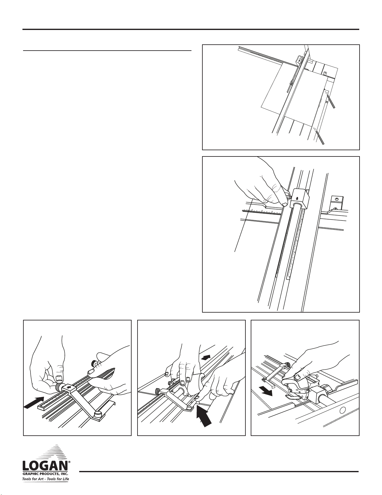
Squaring Arm Assembly
NOTE: There are two squaring arms from which to choose. The 32” arm is used for straight
cutting. The 9” is an option if straight cutting is unnecessary or saving space is required.
1. Line up squaring arm along side of slot, ensuring the bottom of the v-groove is
underneath screw. (Fig. 10)
2. Slide into the slot.
3. Align slots and tighten screw. (Fig. 11)
4. Slide stop onto squaring arm. (Fig. 12)
Top Production Stop Assembly
1. Slide top production stop onto measuring bar. (Fig. 13)
2. Tighten knob.
Straight Cutting Board to Size Using 32” Squaring Arm
1. Remove mat guide and slip sheet.
2. Loosen bottom production stop and move to bottom of cutting bar. (Fig. 14)
3. Lift Handle bar into up position.
4. Set squaring arm stop to dimension of cut. Place mat (color side down) against
squaring arm and stop. (Fig. 15)
5. Lower handle bar into down position so cutting bar rests on mat.
6. Slide cutting head past far end of mat.
7. Rotate straight cut blade holder down until lock down pin “pops” into lock slot.
(Fig. 16)
8. Holding the cutting head as shown (Fig. 17), pull the cutting head until the board is
completely cut.
NOTE: Do not apply downward pressure on blade holder. The lock down pin is holding blade
at proper depth.
9. IMPORTANT: After finishing the cut, pull lock down pin out and rotate blade holder to
safety position. (Fig. 18)
NOTE: It is dangerous to leave the blade set in the “cut” position.
Fig. 10
Fig. 11
Fig. 12
Fig. 13
Fig. 16
Fig. 14
Fig. 17
Fig. 15
3
2
1
Fig. 18
5
Logan Graphic Products Inc., 1100 Brown St, Wauconda, IL 60084 847-526-5515 cs@logangraphic.com
LoganGraphic.com

Instruction Manual
Fig. 22
Framer’s Edge Elite Mat Cutter
Model 650-1 / 655-1 / 660-1
Bevel Cutting Mat Openings
Using Line to Line Method
1. Install mat guide and set to desired border width. Tighten black knobs.
2. Loosen bottom production stop and move to bottom of cutting bar. (Fig.19)
3. Lift handle bar and replace/install slip sheet.
NOTE: For best results ALWAYS use a slip sheet when bevel cutting. A slip sheet is a scrap piece
of matboard which is at least as long as the mat you are cutting and at least 4” wide. Your first slip
sheet is included. The slip sheet will need to be changed periodically. Move the slip sheet slightly
after each cut to avoid cutting into previous scores that may cause the blade to flare out, causing a
curve in your cut.
3. Place the mat (color side down) against the squaring arm and against the mat guide. (Fig. 20)
4. Lower the handle bar. With a pencil, draw a line on the back of the matboard using the left side
of the cutting bar as a guide. Do this for the remaining three sides of the mat. (Fig. 21)
5. Slide the cutting head into position so that the edge of the metal near the green arrow on the
indicator plate is directly over the top marked line. (Fig. 22)
6. Rotate the bevel blade holder down completely to seat the blade into the mat.
NOTE: Press your finger against the side of the indicator and the mat firmly enough to not allow cut-
ting head to “creep forward” when inserting blade, which can cause an overcut. (Fig. 23)
7. Maintaining downward pressure, pull the cutting head toward yourself until edge of the metal
near the red arrow on the indicator plate is directly over the bottom marked line. (Fig. 24)
NOTE: Do not push down on the handle bar when cutting, as this will flex the cutting bar upwards
and prevent the blade from cutting through the matboard.
8. Rotate the bevel blade holder up to the neutral position and lift the handle bar to an upright position.
9. Turn the mat 1/4 turn to the right and make sure that the mat is down against the squaring arm
and against the mat guide on the left.
10. Continue steps 5 through 8 until all four sides are cut.
Fig. 19
Fig. 20
3
2
1
E
L
A
C
S
T
E
S
Fig. 21
Fig. 23
Fig. 24
Logan Graphic Products Inc., 1100 Brown St, Wauconda, IL 60084 847-526-5515 cs@logangraphic.com
6
LoganGraphic.com
Instruction Manual
Framer’s Edge Elite Mat Cutter
Model 650-1 / 655-1 / 660-1
Using Production Stops
1. Install mat guide and set to desired border width. Tighten black knobs.
2. Lift handle bar and replace/install slip sheet.
NOTE: For best results ALWAYS use a slip sheet when bevel cutting. A slip
sheet is a scrap piece of matboard which is at least as long as the mat you
are cutting and at least 4” wide. Your first slip sheet is included. The slip
sheet will need to be changed periodically. Move the slip sheet slightly after
each cut to avoid cutting into previous scores that may cause the blade to
flare out, causing a curve in your cut.
3. Place the mat (color side down) against the squaring arm and against
the mat guide. (Fig. 25)
4. Slide the bottom production stop up to the increment on the scale of
the border size you wish to cut. (Fig. 26)
5. Slide the top movable stop up to the increment on the scale of the
border size you wish to cut. (Fig. 27)
6. Slide the cutting head into position in front of the top edge of the
matboard. As the movable stop approaches the edge of the matboard,
press down on the stop foot with your left index finger until it gently
makes contact with the top edge of the mat. (Fig. 28)
7. Holding the stop foot in place with your finger, rotate the blade holder
down to enter the blade into the mat.
Fig. 25
Fig. 26
E
L
A
C
S
T
E
S
3
2
1
8. Release the stop foot with your finger, so that it raises above the edge
of the mat board and pull the cutting head towards yourself until it
makes gentle contact with the bottom production stop. (Fig. 29)
9. Turn the mat 1/4 turn to the right and make sure that the mat is down
against the squaring arm and against the mat guide on the left.
10. Continue steps 6 through 9 until all four sides are cut.
Fig. 27
Fig. 28 Fig. 29
Logan Graphic Products Inc., 1100 Brown St, Wauconda, IL 60084 847-526-5515 cs@logangraphic.com
7
LoganGraphic.com

Instruction Manual
Framer’s Edge Elite Mat Cutter
Model 650-1 / 655-1 / 660-1
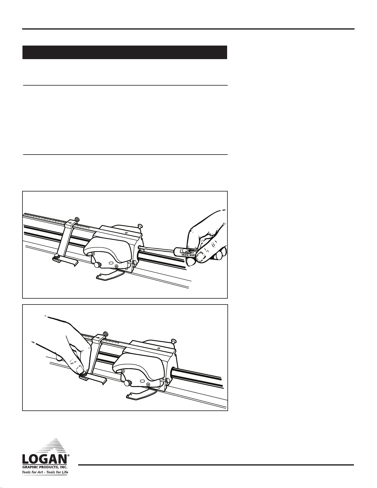
Adjustments
Bevel blade depth adjustment
1. Turn depth adjustment screw clockwise to increase depth or coun-
terclockwise to decrease depth. (Fig. 30)
NOTE: Use the blade window to reference various blade depths.
NOTE: It is always ideal to have just enough blade depth to slice through
the mat you are cutting and score slightly into the slip sheet. Extra blade
depth can allow the blade to flex, resulting in hooks or curves in the cut.
Extra blade depth can also cause the blade to start its cut sooner and
stop its cut later than needed, resulting in overcuts.
Cutting Head Slide Adjustment
If cutting head is too loose, wobbles up and down OR rocks side to
side, you will need to adjust the cutting head.
Bushing Adjustment
1. To eliminate side to side rocking, tighten each adjustment screw
a very small amount using Allen Wrench. (Fig. 32)
Fig. 30
Fig. 31
2. Test rocking and readjust until rock is eliminated and sliding
motion is smooth.
Bearing Adjustment
1. To eliminate wobble up and down, tighten adjustment screw a
very small amount using Allen Wrench. (Fig. 31)
2. Test wobble and readjust until wobble is eliminated and sliding
motion is smooth.
Fig. 32
Logan Graphic Products Inc., 1100 Brown St, Wauconda, IL 60084 847-526-5515 cs@logangraphic.com
8
LoganGraphic.com
Instruction Manual
Framer’s Edge Elite Mat Cutter
Overcut Screw Adjustments
NOTE: These adjustments are only needed when production stops are being used.
Bottom Overcut Adjustment
1. If over or under cuts appear at the BOTTOM of the cut when using the production
stops even after a blade depth adjustment, use the Logan screwdriver provided to
make slight adjustments on the overcut adjustment screw on the back of the cutting
head. This screw will fine tune the BOTTOM over/under cut only when using the
production stop.
2. To adjust, use Logan screwdriver to turn screw in (clockwise) to increase overcut or
turn screw out (counterclockwise) to decrease overcut. (Fig. 33)
Top Overcut Adjustment
1. Loosen knob to allow leg to slide. Slide leg away from cutting head to decrease
overcut or toward cuting head to increase overcut. Tighten knob to lock leg into
position. (Fig. 34)
Fig. 33
Model 650-1 / 655-1 / 660-1
Fig. 34
Logan Graphic Products Inc., 1100 Brown St, Wauconda, IL 60084 847-526-5515 cs@logangraphic.com
9
LoganGraphic.com

Instruction Manual
Framer’s Edge Elite Mat Cutter
Model 650-1 / 655-1 / 660-1
Cutting Board Adjustments
Fig. 35
Fig. 36
PLACE
SQUARE HERE
Re-Squaring the Squaring Arm
Tools needed: Screwdriver, Carpenter’s Square
Before making any adjustments to the squaring arm, make sure that the machine is truly
out of square, not the mat board, by using the squareness test.
ATTENTION: It is common for 32” x 40” sheets of mat board to be un-square when
bought. Take this into account before making any adjustments to the squaring arm.
Squareness Test
1. Place the carpenter’s square against the right hand side of the guide rail and
down against the squaring arm. (Fig. 35) Lock to see if there are any gaps
between the framing square and the squaring arm. If so, the squaring arm needs
to be adjusted.
To Re-Square
1. By looking at where the gap is, you can determine which way the squaring arm needs
to go, in order to be square again.
2. Remove the squaring arm and locate the two screws inside of the slot.
3. To adjust, you must turn screws A & B in equal but opposite directions. To move the
far right end of the squaring arm towards the top end of the machine, turn adjustment screw B inward (clockwise) about a quarter turn, and turn adjustment screw A
outward (counter-clockwise) a quarter turn. (Fig. 36)
4. Re-install the squaring arm and check for square. This is a trial and error method.
In some cases more than a quarter turn is needed, in some cases, less.
Logan Graphic Products Inc., 1100 Brown St, Wauconda, IL 60084 847-526-5515 cs@logangraphic.com
10
LoganGraphic.com
Instruction Manual
Framer’s Edge Elite Mat Cutter
Model 650-1 / 655-1 / 660-1
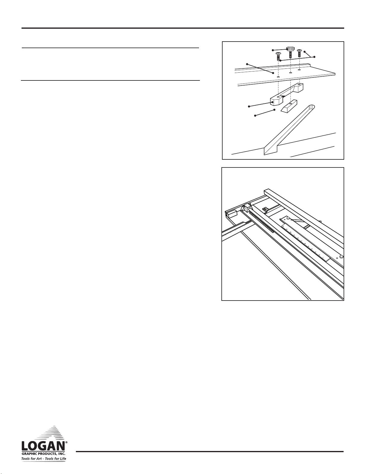
Mat Guide Assembly
If mat guide wedge becomes unscrewed from mat guide, reassemble making sure
angle of wedge is aligned correctly. (Fig. 37)
Re-parallel Mat Guide
Tools Needed: Phillips Screwdriver, Ruler
To re-parallel the Mat Guide, first determine that the Mat Guide is out of parallel by
doing a parallel test.
Parallel Test:
1. Lock the Mat Guide at the 2” mark on the scale.
2. Place a scrap piece of matboard under the Guide Rail and up against the Mat
Guide at the far end of the machine.
3. Using a pencil, mark a line across the matboard.
4. Slide the mat all the way down near where you are standing keeping under the
Guide Rail.
5. Mark another line across the matboard.
6. The piece of matboard should now appear to only have one single line across it.
If the two lines drawn do not line up with each other, the Mat Guide needs to be
re-paralleled.
To Re-parallel:
1. Release the Mat Guide.
2. Use a Phillips head screwdriver to loosen the four screws on either side of the
black knobs one turn.
Fig. 37
Mat Guide
#602 Slide
#603 Wedge
Fig. 38
#112N Mat
Guide Knob
#604 Mat
Guide
Screws (2)
3. Place a ruler or straight edge between the Mat Guide and the Guide Rail. (Fig. 38)
4. Slide the Mat Guide against the straight edge and the Guide Rail. Make sure
both the Mat Guide and the Guide Rail are making solid contact on both
sides of the straight edge.
5. Re-tighten the Black Knobs first.
6. Then re-tighten the four screws. Do another parallel test to ensure that the Mat
Guide is now parallel.
Logan Graphic Products Inc., 1100 Brown St, Wauconda, IL 60084 847-526-5515 cs@logangraphic.com
11
LoganGraphic.com

Instruction Manual
Troubleshooting
Problem Solution
•
Hooks or Curves
Overcut on Top Cut
Overcut on Bottom Cut
Mat Borders Uneven
Ragged Bevel Cut
Not Cutting Through
Blade depth set too deep.
•
Blade is dull.
•
Blade is catching on previous cut in Slip Sheet.
•
Uneven pressure being applied to
Cutting Head during cut.
•
Blade depth set too deep.
•
If too small - align start and stop indicator slightly below
pencil line and cut.
•
If too big - align start and stop indicator slightly above
pencil line and cut.
•
Mat Guide not parallel.
•
Cutting without a Slip Sheet.
•
Slip Sheet is worn out.
•
Not changing the blade often enough.
•
Machine not on a level surface.
•
Not using a Slip Sheet as least as long as the
mat you are cutting.
•
Blade depth set too shallow.
Framer’s Edge Elite Mat Cutter
Model 650-1 / 655-1 / 660-1
Helpful Hints
Avoid Board Warp - Always store your Mat Cutter flat.
Clean Guide Rail - Only use evaporative solvents such as lighter fluid or alcohol. Do not lubricate the Guide Rail.
Cutting a Border Less Than 3/4” - Mark mat (back side) using a pencil and do not use Mat Guide.
Blade Life - Use only authentic Logan blades to ensure best results. No two blades last the same amount of time. Size of mats and differences in
mat board effect blade life. It is best practice to use a new blade whenever starting a new project.
Warranty
Logan Graphic Products, Inc. (“Logan”) warrants the model 650-1 / 655-1 / 660-1 FRAMER’S EDGE ELITE to be free from defects in parts
and workmanship for a period of two years from the date of original purchase. Logan warrants that it will either repair or replace, in its sole
discretion, any necessary replacement parts found to be defective. Should the product need to be returned to Logan for repair or replacement
parts, authorization for any return must come from Logan in writing. Costs of returning the product to Logan, including insurances, shall be
borne by the purchaser. Logan shall not be liable for any damages or losses, incidental or consequential, direct or indirect, arising from the
use of this product. This warranty extends only to the original purchaser and is not assignable or transferable. This warranty is in lieu of all
other warranties, expressed or implied. Be advised that any Logan products purchased as “new” from an unauthorized dealer, such as an
online auction site or similar, may be void of their warranty.
Logan Graphic Products, Inc.
1100 Brown Street Wauconda, IL 60084
800/331-6232 847/526-5515
Logan Graphic Products Inc., 1100 Brown St, Wauconda, IL 60084 847-526-5515 cs@logangraphic.com
12
LoganGraphic.com
 Loading...