

Page 1
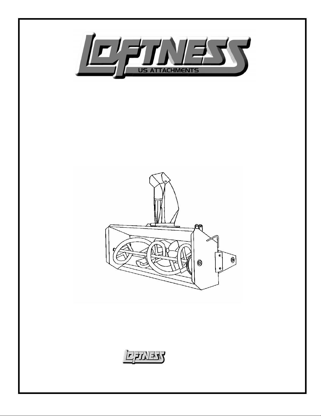
Snowblower
661S 721S 781S 841S
Operator’s Manual & Parts Book
(2001 2002 2003 2004)
Model Number: _________________
Serial Number: __________________
Date of Purchase: ________________
Equipment, Inc.
650 So. Main Street - PO Box 337 - Hector, MN 55342
Business Phone: 320-848-6266 * Fax: 320-848-6269 * Toll Free: 1-800-828-7624
N14810 December,
2003
Specialized
Page 2

LOFTNESS SPECIALIZED EQUIPMENT, INC.
WARRANTY POLICY
The warranty policy begins upon delivery of the unit to the original customer.
Loftness six (6) month warranty policy covers Timber Axes, Timber Ax Extremes, Carbide Cutters, Carbide Cutter
Extremes, Brush Shredders, Flail Mowers, and Orchard Shredders.
Loftness one (1) year warranty policy covers only the Crop Shredders, Snowblowers, and Kwik-Piks.
If any Loftness product is used as a rental unit, the warranty period extends for only 30 days from the delivery date to the
original customer.
Loftness Specialized Equipment, hereinafter referred to as LOFTNESS, a manufacturer of quality machinery since 1956, warrants new
LOFTNESS machinery and/or attachments at the time of delivery to the original purchaser, to be free from defects in material and
workmanship when properly set up and operated in accordance with the recommendations set forth in the LOFTNESS Operator’s
Manual.
LOFTNESS’ liability for any defect with respect to accepted goods shall be limited to repairing the goods at an authorized dealer or
other LOFTNESS designated location, or replacing them as LOFTNESS shall elect. The above shall be in accordance with
LOFTNESS warranty adjustment policies. This warranty shall not apply to any machine or attachment which shall have been repaired
or altered outside the LOFTNESS factory or authorized LOFTNESS dealership or in any way so as in LOFTNESS’ judgment, to
affect its stability or reliability, nor which has been subject to misuse, negligence or accident, nor to any machine or attachment which
shall not have been operated in accordance with LOFTNESS’ printed instructions or beyond the company recommended machine
rated capacity.
WARRANTY REQUIREMENTS
Warranty registration form must be filled out and returned to Loftness Specialized Equipment to validate all future warranty
claims.
LIMITATIONS OF WARRANTY
All Products – LOFTNESS products are designed to provide years of dependable service when proper use and maintenance is adhered
to. The potential for misuse in many applications exists, therefore a limited warranty is provided as follows:
All Shredders, Axes, Cutters & Mowers – Rotor Balance: Critical rotor balance can be affected by conditions beyond LOFTNESS’
control, such as the operation of a shredder beyond the Company’s rated capacity, improper knife replacement, missing knives, striking
foreign objects, lack of lubrication, etc. Any failure resulting from running in as “out-of-balance” condition, such as, but not limited to
bearing and or drive-line failure, metal fatigue, cracks, etc. will be considered abuse and will not be covered under warranty.
LOFTNESS may elect to have an area representative evaluate the condition of the machine before warranty is considered.
To receive a warranty claim, a return authorization from LOFTNESS must be obtained. The failed part may then be returned in an
untampered status. This warranty does not include freight or delivery charges incurred when returning machinery for servicing. Dealer
mileage, service calls and pick-up/delivery charges are the customer’s responsibility.
EXCLUSIONS OF WARRANTY
Except as otherwise expressly stated herein, LOFTNESS makes no representation or warranty of any kind, expressed or implied, and
makes no warranty of merchantability in respect to its machinery and/or attachments and makes no warranty that its machinery
and/or attachments are fit for any particular purpose. LOFTNESS shall not be liable for incidental or consequential damages for any
breach of warranty, including but not limited to inconvenience, rental or replacement equipment, loss of profits or other commercial
loss. Upon purchase the buyer assumes all liability, all personal injury and property damage resulting from the handling, possession or
use of the goods by the buyer.
No agent, employee, or representative of LOFTNESS has any authority to bind LOFTNESS to any affirmation, representation or
warranty concerning its machinery and/or attachments except as specifically set forth h
erein.
August, 2006
Page 3

Owner’s Manual (Snowblower)
Snowblower
Table of Contents
Section 1 - Safety
Safety Instructions ......................................................................................................................................................... 1
Safety Instructions for Operation ................................................................................................................................ 2
Section 2 - Operating
Equipment Set-up .......................................................................................................................................................... 5
Operating Instructions .................................................................................................................................................. 7
Section 3 – Maintenance
Maintenance .................................................................................................................................................................... 9
Lubrication ...................................................................................................................................................................... 9
Trouble Shooting ............................................................................................................................................................10
Storage ..............................................................................................................................................................................11
Bolt Torque Chart ...........................................................................................................................................................12
Page
Section 4 – Service Parts
Ordering Service Parts ...................................................................................................................................................14
Return Policy ...................................................................................................................................................................14
Decal List .........................................................................................................................................................................15
Decal Locations ...............................................................................................................................................................16
Parts Lists and Drawings ...............................................................................................................................................17
N14810 September, 2002
Page 4

Specialized
Equipment, Inc.
650 So. Main St. - PO Box 337 - Hector, MN 55342
Business Phone: 320-848-6266 * Fax: 320-848-6269 * Toll Free: 1-800-828-7624
Dear Customer:
Thank you for your decision to purchase a snowblower from Loftness Specialized Equipment, Inc. It has been
designed to provide years of profitable and dependable service. To insure maximum performance of your
snowblower, it is mandatory that you thoroughly study the owner’s manual and follow its recommendations.
Proper operation and maintenance are essential to maintain and maximize the life of the machine and to prevent
damage or injury.
It is the owner’s responsibility to:
• Operate and maintain this snowblower in a safe manner and in accordance with all
applicable local, state, and federal codes, regulations and/or laws, and in compliance
with on-product labeling and these instructions.
• Make sure that all personnel have read this owner’s manual and thoroughly understand
safe and correct operating, installation, and maintenance procedures.
• Provide impact-resistant shielding on the power unit to protect the operator from the
possible dangers of flying debris.
• Make sure the snowblower is set-up correctly before being placed in service. It should
be serviced at regular intervals thereafter, in accordance with procedures outlined in
this manual.
• Fulfill all warranty obligations so as not to void the warranties. The warranty section at th
beginning of this manual outlines the warranty policy of Loftness Specialized Equipment, Inc.
Loftness Specialized Equipment, Inc. reserves the right to make product improvements to the equipment at any
time.
We welcome you to the satisfied family of Loftness equipment owners.
Gloria Nelson, President
Steve Nelson, Vice-President
Dave Nelson, Vice-President
Page 5

Section
1
Safety
Page 6

WARNING
Because of the potential safety hazard to eyes from
hydraulic leaks and/or flying debris, “USE OF
PROTECTIVE EYEWEAR IS ABSOLUTELY
MANDATORY” for operator and others in the work
area.
Due to the possible danger of flying debris, it is
“ABSOLUTELY MANDATORY that IMPACTRESISTANT SHIELDING” be provided on the
power unit to protect the operator. The owner is
responsible for providing the operator protection
devices on the power unit.
Page 7

Owner’s Manual (Snowblower)
Safety Instructions
Safety First
Accidents can be prevented by recognizing the
causes or hazards before an accident occurs, and
doing something about them. Read this manual
carefully and become familiar with the controls and
proper use of the machine. Know how to stop the
unit by disengagement of the controls. Be sure the
operator knows how to exercise the “Mandatory
Shut-down Procedure” (section 1, page 2).
Regardless of the care used in the design and
construction of this equipment, there are some areas
that cannot be safeguarded without interfering with
accessibility and efficient operation.
These message alert symbols, shown below, are
intended to identify and provide information that
must be heeded for proper safe operation of the
equipment and to prevent damage or deterioration
of the equipment. In this manual and on labels used
on this snowblower the words “Danger”,
“Warning”, and “Caution” are used to indicate the
following:
The following safety information is a general
overview of precautions that should be adhered to:
1. Read this manual carefully. Become
thoroughly familiar with the controls
and proper use of the machine. Insure
that all operators know how to stop the
unit by disengagement of the controls
using the mandatory shut-down
procedure.
2. Remember, it is the owner’s
responsibility for communicating all
information on the safe use and proper
maintenance of this machine.
3. Never allow children to operate
equipment. Allow adults to operate the
equipment only after receiving the
proper instructions. Keep the area of
operation clear of all unauthorized
persons.
4. Remove from area of operation all
foreign objects such as sticks, wire,
rocks, etc., that might become tangled in
the rotor, causing damage to the
snowblower or thrown from the
DANGER - (white lettering on red back ground) Warns of an
immediate hazard which, if
not avoided, will result in
severe personal injury or
death.
snowblower striking other objects.
5. Never attempt to make any adjustments
while the engine is running or the key is
in the “ON” position of the power
source. Before leaving the operator’s
position, disengage power to the
WARNING - (black lettering on orange
background) Refers to a
potentially hazardous
situation which, if not
avoided could result in
severe personal injury
or death.
Safety Instructions for Operation and
Maintenance
snowblower and remove ignition key.
6. Disengage PTO, clutch, or hydraulic
valve and place power source controls in
neutral or park before starting engine.
The following safety warnings are used here and on
CAUTION - (black lettering on yellow
back-ground) Refers to a
potential hazard or unsafe
practice which may result in
the snowblower. Become familiar with them before
operating this machine.
minor personal injury.
N14809 1/01
1
Page 8

Owner’s Manual (Snowblower)
Safety Instructions for Operation and
Maintenance Continued:
Mandatory Shut-Down Procedure:
• Move throttle to slow idle position.
• Disengage all power to the snowblower
(hydraulic valve, or clutch, etc ).
• Shut off engine and remove the key.
• Wait until the auger has stopped completely
before inspecting the unit.
CAUTION:
• Failure to follow safety, operating, and maint-
enance instructions could result in death or
serious injury to the operator or bystanders, to
the operator or bystanders, poor operation, or
costly breakdown.
• Become familiar with and know how to use all
safety devices and controls on the snowblower
before attempting to operate the unit. Know
how to stop the unit before starting it.
• Should excessive vibration occur, disengage the
power take off or hydraulic valve immediately
and do not continue to operate the machine
until the problem has been determined and
corrected.
• Do not start, operate, or work on this machine
until you have carefully read and thoroughly
understand the contents of this manual, the
operator’s manual for your loader, and the EMI
skid-loader safety manual provided with the
snowblower (located in section 5 of this
manual).
• Keep children, spectators and other workers off
and away from the machine while it is operating
or engine is running. Do not carry passengers.
• Before inspecting, cleaning, lubricating,
adjusting or servicing any part of the snowblower, always exercise the “Mandatory ShutDown Procedure” (section 1, page 2). After
service has been performed, be sure to restore
all guards, shields and covers to their original
position.
• Read and observe all warnings decals on the
machine before attempting to operate the
snowblower. Do not attempt to operate this
machine unless all factory devices and decals are
in place. Keep safety decals clean of dirt and
grime. Keep all guards, shields and decals in
place.
• The operator must not use drugs or alcoholic
drinks which would impair his alertness or
coordination while working. An operator who is
taking prescription drugs must get medical
advice to determine if he can safely operate a
machine.
• Do not direct discharge spout towards people,
houses, vehicles, or other objects that could be
damaged.
• Stay alert for hidden hazards or traffic.
• Before using a snowblower on a new job site,
check the rules and regulations at the location.
The rules may include an employer’s work safety
requirements.
• Never operate the snowblower without good
light and visibility.
• Make sure all controls, (levers, pedals and
switches), are in a neutral position before
starting the loader engine.
N14809 1/01
2
Page 9

Owner’s Manual (Snowblower)
Safety Instructions for Operation and
Maintenance Continued
• To prevent serious personal injury from
escaping high pressure fluid, never attempt to
inspect, service or disassemble any part of the
hydraulic system until all pressure has been
relieved from the system.
WARNING:
• Keep all guards, shields and decals in place.
• Keep hands, feet and clothing away from
moving components.
• Do not wear loose or baggy clothing around
rotating machinery. Machine must be clear of
people, tools, and other objects before engaging
PTO or hydraulic valve.
• Before working under any hydraulically
controlled implement, be certain it is securely
blocked!
• Because of the potential safety hazard to eyes
from hydraulic leaks and/or flying debris, use of
protective eye ware is absolutely mandatory for
operator and others in the work area.
• Always use an approved roll bar and seatbelt for
safe operation. Overturning a loader without a
roll bar and seatbelt can result in injury or death.
• Use the handholds and step plates when getting
on and off the loader to prevent falls. Keep
steps and platform cleared of mud and debris.
• Operate the snowblower only from the
operator’s seat.
• Keep your feet on the pedals, (floor plates) seat
belt fastened snuggly and seat bar lowered, (if
equipped), when operating the snowblower.
• Never operate the snowblower in a lifted
position. Work only on the surface that the
loader is standing on.
• Do not operate the snowblower above the rated
rpm.
DANGER:
• Before leaving the operator’s position for any
reason or allowing anyone near the snowblower,
always exercise the following “Mandatory Shutdown Procedure” (section 1, page 2).
Operations Safety:
Because this machine will be operated in a
potentially hazardous environment, it is absolutely
mandatory that you read and follow these safety
precautions.
WARNING:
• Stay alert for hidden hazards or traffic. Do not
carry passengers.
• Never operate the snowblower without good
light or visibility.
• Engage the hydraulic valve slowly at idle speed
to prevent unnecessary stress to driveline.
• After striking a foreign object, be sure to
exercise “Mandatory Shut-down Procedure”
(section 1, page 2). Thoroughly inspect
snowblower for any damage before restarting
and operating.
• Should excessive vibration occur, disengage
hydraulic valve immediately. Do not continue
operation of snowblower until the problem has
been detected and corrected. Be sure to exercise
the “Mandatory Shut-down Procedure (section
1, page 2).
N14809 1/01
3
Page 10

Owner’s Manual (Snowblower)
Operations Safety Continued:
• Disengage power to snowblower when
transporting or not in use.
• When transporting the snowblower on the road
at day or night, provide adequate warning to the
operators of other vehicles.
• Never park on a steep incline.
• Do not leave equipment in raised position.
• Due to the possible danger of flying debris,
impact-resistant shielding must be provided for
the operator. The owner is responsible for
providing the operator protection devices on the
power unit.
• Do not allow any people or animals within 1000
feet of the work area while operating this
machine
• Thoroughly clear the work area of all foreign
objects such as bottles, rocks, wire, etc. before
starting shredder.
• Aways operate shredder level with the ground
WARNING:
• Never operate the snowblower without guards,
shields, plates or other safety precaution devices
in place. Shields are for your protection, please
keep all shields in place.
• Do not operate on extremely steep slopes.
• Always remove snow by traveling in an up and
down direction on slopes. To avoid loss of
control and to prevent overturn, never drive
diagonally across the slope.
• Reduce speed when turning.
• Before servicing or adjusting the snowblower, or
removing material from it, be sure to exercise
the mandatory shut-down procedure.
• Be sure the auger has stopped completely before
servicing.
• Be especially careful not to touch attachment
parts which might be hot from operation.
Allow such parts to cool before attempting to
maintain, adjust, or service.
(front to rear).
• Never operate snowblower over 2 feet above
the ground.
• When high pressure fluid escapes, it can be
almost invisible, yet have enough pressure to
penetrate the skin and enter the blood stream.
Never attempt to use hands to search for
suspected oil leak. If injured by escaping fluid,
consult a doctor at once! Serious reaction or
infection can occur if proper medical treatment
is not obtained immediately.
N14809 1/01
4
DANGER:
• Never get off skid-steer while it is in motion, as
entanglement can cause personal injury or death.
• Keep hands and feet out! Do not step on or
climb over the unit while machine is in
operation, or engine is running. Do not carry
passengers.
Page 11

Section
2
Operating
Page 12

WARNING
Because of the potential safety hazard to eyes from
hydraulic leaks and/or flying debris, “USE OF
PROTECTIVE EYEWEAR IS ABSOLUTELY
MANDATORY” for operator and others in the work
area.
Due to the possible danger of flying debris, it is
“ABSOLUTELY MANDATORY that IMPACTRESISTANT SHIELDING” be provided on the
power unit to protect the operator. The owner is
responsible for providing the operator protection
devices on the power unit.
Page 13
Owner’s Manual (Snowblower)
Set-up and Operating Instructions
Equipment Set-up:
The initial set-up of this machine will require you to
become familiar with all hazard warnings and safety
precautions listed in this manual. Review the
illustrated parts lists (section 4) to become familiar
with the component parts and how they are
assembled.
The snowblower may be shipped in a wooden
packing crate with the spout and rotator controls
packaged separately. The spout deflector controls
will be pre-assembled onto the spout. Unpack all
components and assemble the spout and rotator
controls onto the snowblower as follows:
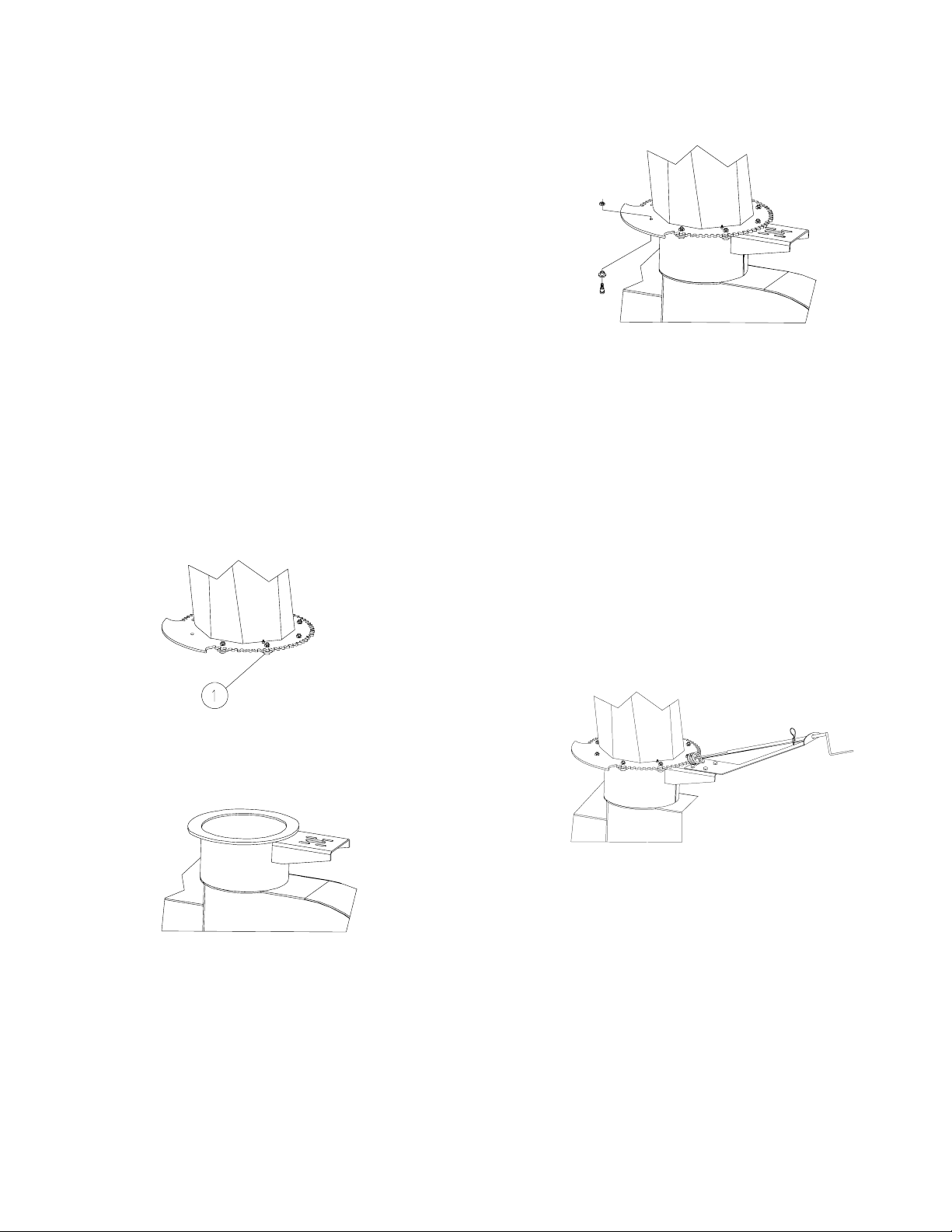
1. Assemble the 1/2” step washers (Figure 1, item
#1), 1/2” x 3/8” shoulder bolts and lock nuts
onto the spout gear on one side only of the
spout, but do not tighten down.
washers, shoulder bolts and lock nuts, then
tighten.
Figure 3
4. Rotate the spout by hand to check for binding,
re-adjust the bolts if binding occurs as the spout
should rotate freely.
5. Attach the spout rotator controls onto the
bracket as shown below (figures 4, 5 or 6).
• The standard hand crank control (figure 4)
will use (4) 3/8” bolts, flat washers, lock
washers and nuts to attach the crank onto
the bracket as shown, do not tighten the
bolts, then align the spout rotator gear and
the hand crank gear. Tighten the bolts and
check rotation of spout, adjust if binding
occurs.
Figure 1
2. Apply grease onto the spout base ring (Figure 2)
Figure 4
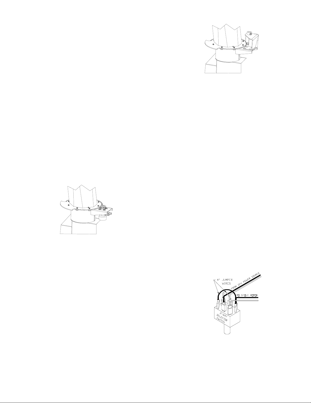
• The optional hydraulic spout control (figure
5) will be attached by first placing the spacer
Figure 2
washer (see parts breakdown in section 4)
on the motor and around the alignment ring.
3. Slide the spout onto the base ring (Figure 3)
checking to insure that the step washers catch
Make sure that the washer is properly seated.
Then position
the base ring, install the remaining step
N14809 1/01
5
Page 14
Owner’s Manual (Snowblower)
Set-up and Operating Instructions Continued
Equipment Set-up Continued:
the motor under the mounting bracket with
the output shaft protruding upward thru the
bracket and with the ports facing outward,
away from the snowblower. Use the (4) hex
head 3/8” x 1-1/4” grade 5 bolts, flat
washers and lock washers to secure the
motor into place, but do not
tighten. Slide the drive sprocket and 1/4” x
1” key onto the output shaft of the hydraulic
motor. Adjust the sprocket and spout gear
teeth for alignment. Tighten the bolts to
secure rotator motor. Adjust the drive
sprocket so that it’s centered on the spout
gear or evenly spaced between the sprocket
guides. Tighten the set screw on the
sprocket. Attach the hydraulic hoses
(supplied by customer), check rotation of
spout, adjust if binding occurs.
Figure 6
1. Mount the 2-way selector switch in a
convenient location near the operator.
2. Select an appropriate 12 volt power source
that will supply 10 amp’s continuously.
3. Install a 20 amp inline fuse to the power
source.
4. Connect a red 14 ga. wire from the outlet of
the fuse to the 2-way selector switch
terminal (figure 7). Avoid hot or moving
parts when routing wires.
5. Locate the main ground wire from the
battery. Install a black 14 ga. wire to the
main ground (Do Not ground to the frame
of the machine, connect directly to the main
ground wire). Securely torque the hardware
retaining the main ground to the harness
ground wires.
Figure 5
• The optional electric spout control (figure 6)
is pre-assembled and will use (4) 3/8” bolts,
flat washers, lock washers and nuts to attach
6. Connect the black 14 ga. wire from the main
ground to the 2-way selector switch terminal
(figure 7). Avoid hot or moving parts when
routing wires.
the control onto the bracket as shown, do
not tighten the bolts, then align the spout
rotator gear and the drive sprocket. Tighten
the bolts, and check rotation of spout, adjust
if binding occurs.
Attach the wiring harness for the electric spout
control option (figure 7) as follows:
N14809 1/01
Figure 7
6
Page 15

Owner’s Manual (Snowblower)
Set-up and Operating Instructions Continued
Equipment Set-up Continued:
7. Connect a second set of 14 ga. wires from
the 2-way selector switch to the electric
spout motor. Attach 4” jumper wires to
connect opposite terminals on the switch
(figure 7).
8. Check the sprockets and drive chain for
• The chain and sprockets should be inspected
should be inspected for alignment and tension
on the initial use, and a periodic check should
be made to keep them in alignment.
• Adjust the chain idler and re-tighten after one
(1) hour of use. Chain should have about one
inch of deflection.
alignment and proper tension on the chain.
Chain should have approximately one inch
(1”) of deflection.
9. Check all bolts and set screws to insure that
they are tight.
10. Check to make sure that all shields are in
place and secure.
The Loftness snowblower is an effective, reliable
machine used for the removal of snow. Before
operating this machine, become familiar with and
study all the hazard warning and safety precautions
listed in this book.
WARNING:
Keep all guards, shields, and decals in place.
• The gearboxes use SAE #90 gear oil and should
be checked regularly. Warranty will not be
allowed when it is evident that gears were run
dry.
• Operator should not raise and lower blower
under heavy loads to gain traction.
• Adjust the blower skid shoes so the cutting
blade is about 1/2” above the ground for best
results.
CAUTION:
Become familiar and know how to use all safety
devices and controls on the snowblower
before attempting to operate the unit. Know how to
stop the unit before starting it.
• Do not use the snowblower as a bulldozer to
push snow, let the blower work its way through
the snow.
• Wet sticky snow requires more power to blow.
The snowblower works better in this type of
snow if it is kept working at its full capacity.
WARNING:
Read and observe all warnings on the machine
before attempting to operate the snowblower.
Do not attempt to operate this machine unless all
factory installed safety devices are in place.
• Best operating speeds of fan depend on snow
conditions.
• Do not use your hands or feet to unplug the
chute. Do not attempt to clear a plugged chute
while the snowblower is under power.
CAUTION:
Before proceeding to perform any adjustments
on the snowblower, exercise the “Mandatory
Shut- down Procedure” (see section 1, page 2).
Disengage the PTO or hydraulic controls by
shutting off the power unit, remove ignition key,
wait for all movement to stop, and then clear the
snow from the chute using a wooden pole.
N14809 1/01
7
Page 16
Owner’s Manual (Snowblower)
Set-up and Operating Instructions Continued
Equipment Set-up Continued:
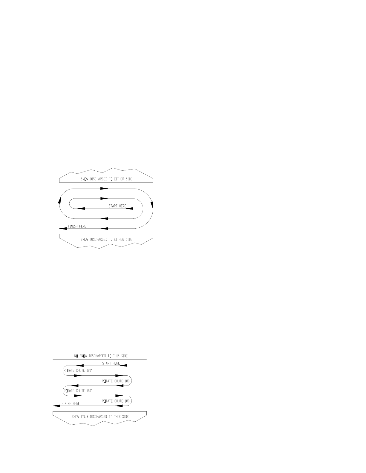
A definite pattern of operation is required to
thoroughly clean the snow area. The patterns shown
below will avoid throwing snow in unwanted places
as well as eliminating a second removal of snow.
Diagram “A” illustrates the removal of sow when it
is possible to throw the snow to the left and right, as
on a long driveway. Start in the middle and work
towards the opposite ends, throwing the snow to
both sides without changing the direction of the
discharge chute.
Diagram “A”
Diagram “B” illustrates the removal of snow when
snow can only be thrown in one direction of the
sidewalk or driveway. Start on one side of the area
that needs to be cleaned, set chute in the direction
required to discharge the snow and proceed. At the
end of the first pass, stop, turn the machine around,
rotate the chute 180 degrees for the return pass.
Completion of each pass will require rotating the
chute 180 degrees to maintain the direction of
discharge to be towards the same area.
Diagram “B”
N14809 1/01
8
Page 17

Section
3
Maintenance
Page 18

Page 19
Owner’s Manual (Snowblower)
Maintenance
The operation and component life of this machine
are very dependent on regular maintenance and
proper lubrication. The frequency of lubrication
recommended is based on normal conditions.
Severe or unusual conditions may determine actual
service requirements.
CAUTION:
Figure 8
Exercise all safety precautions before attempting
to service this equipment by securely blocking any
hydraulic controlled implement and use the
“Mandatory Shut-down Procedure” (section 1,
page 2).
• After service has been performed, be sure to
restore all guards, shields, and covers to their
original positions.
• Before working under any hydraulically
controlled implement, be certain it is securely
blocked!
• Always wear safety goggles or glasses when
working on hydraulic systems to avoid eye
injury and never check for hydraulic leaks by
using your hand. If injured by escaping fluid,
consult a doctor at once! Serious reaction or
infection can occur if proper medical treatment
is not obtained immediately.
Lubrication:
• Never attempt to lubricate the snowblower
with the engine running. Always be sure to
exercise the “Mandatory Shut-down Procedure
(section 1, page 2).
• Check oil levels at the beginning of each
season, before each use and every 25 hours of
operation thereafter. The gearbox should be
drained and refilled to a (1/2) half full level of
SAE 90 gear lubricant at the end of each
season.
• When the snowblower gear case is overfilled,
oil will be forced out breather vent, and
possibly damage seals.
• Lubricate the auger chain with heavy duty
lubricant every 4 hours of operation and after
each adjustment. Maintain approximately one
inch of deflection for proper adjustment.
WARNING:
The driveline and components on these
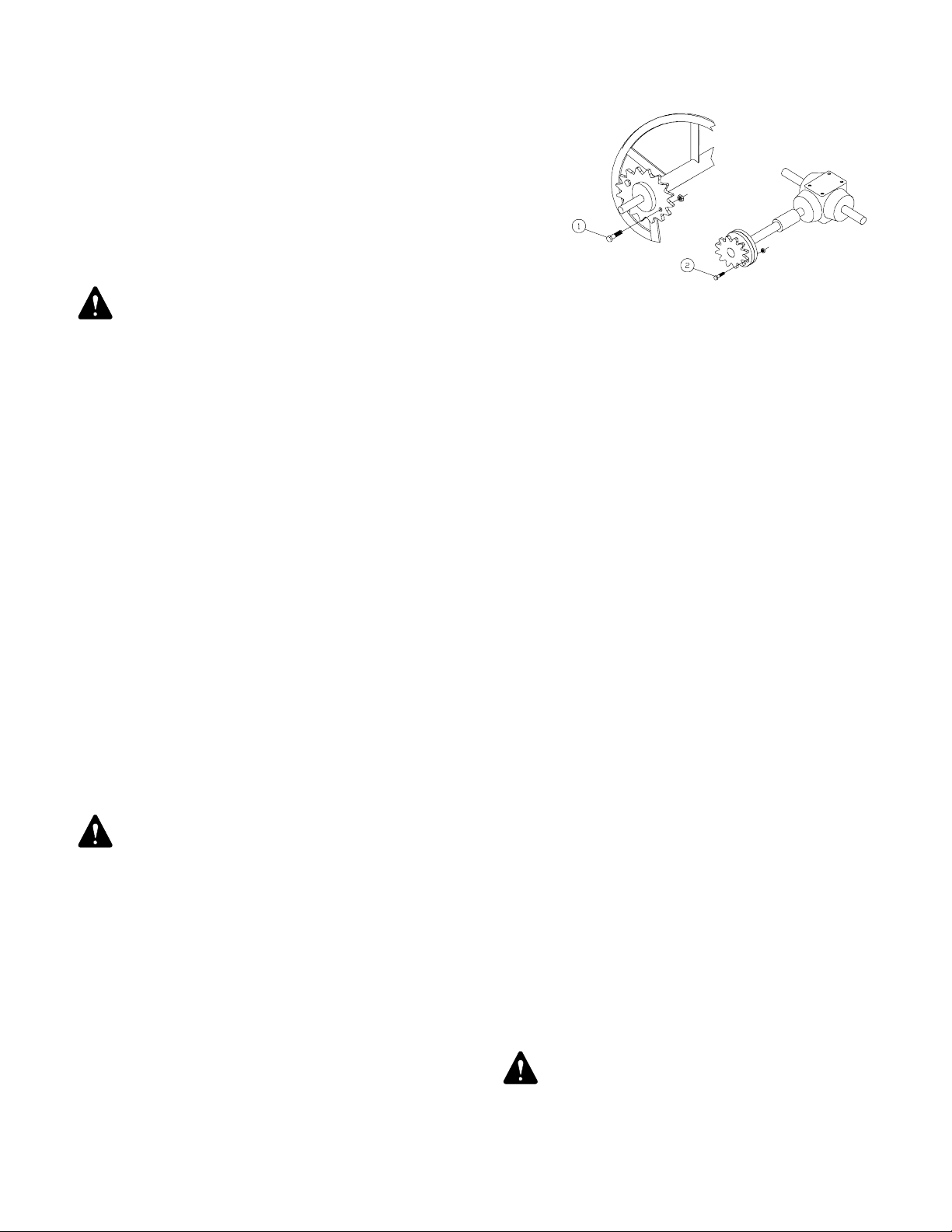
snowblowers are set-up to run at 540 or 1000
RPM with shear bolts placed at the appropriate
connections to protect the equipment if it
becomes clogged and can not run. Refer to figure
8, items #1 & #2 for location of shear bolts.
• Grease the PTO u-joints every 8 hours of
operation and separate the PTO halves to coat
sliding surfaces with oil every 24 hours of
operation.
• Spout bands, gears and worm gears should be
kept greased at all times.
• Grease all bearings every 25 hours.
WARNING: Keep all guards, shields, and
decals in place
.
N14809 1/01
9
Page 20

Owner’s Manual (Snowblower)
Maintenance Continued
Trouble Shooting:
To assist with maintenance, repair, or use of the snowblower, the following list of common problems and
corrections is provided:
Problems: Possible Cause: Solution:
Auger Will Shear Bolts Broken Check and replace any shear bolts located on the auger drive
Not Turn sprocket, cross shaft drive sprocket (see illustration of parts in
section 4).
Auger Chain Broken Replace drive chain (see illustrations of parts in section 4).
Gearbox Not Turning Check shear bolt on PTO, replace if broken (see illustration of
parts in section 4).
Gearbox Failed Repair or replace complete unit.
Internally
Hydraulic Hose Check to make sure they are connected into the correct outlet
Connection ports on the spool valve.
Spout Will Frozen Snow Snow or ice has become compacted on spout rotator gear,
Not Rotate remove as required and clean after each use to avoid freezing.
Gear Alignment Spout rotator gear and drive sprocket have become
misaligned. Realign per instructions given on page 6 & 7 in
section 2.
Hydraulic Hose Check to make sure they are connected into the correct outlet
Connections ports on the spool valve.
Snow Not Compacted with Snow Disengage PTO or hydraulic controls (release all hydraulic
Discharging pressure), turn the tractor off, then using a wooden pole clean
From Spout the snow from the spout.
Fan Not Turning Check shear bolt on PTO, replace if broken or check for
gearbox failure (see illustration of parts in section 4).
N14809 1/01
10
Page 21

Owner’s Manual (Snowblower)
Maintenance Continued
Storage:
Storage at the end of the snow removal season or
between each use, requires an inspection of the
snowblower for repairs and general upkeep to
insure it will be ready for future use. Below is a list
of suggestions.
• With engine stopped, ignition key removed,
and PTO disengaged, clean the snowblower,
especially in areas of drive chain, fan, spout,
and auger where it could become frozen or
rusted together and cause damage when unit is
used next time. Be sure to exercise the
“Mandatory Shut-down Procedure”, (section
1, page 2) before attempting any type of
cleaning or maintenance.
• Repair or replace worn parts.
• Coat moving parts and high wear areas with
oil, especially the chains and lubricate all grease
fitting.
• Repaint all parts and areas where the paint has
become removed to prevent rusting.
• Store the snowblower in a dry place.
N14809 1/01
11
Page 22
Owner’s Manual (Snowblower)
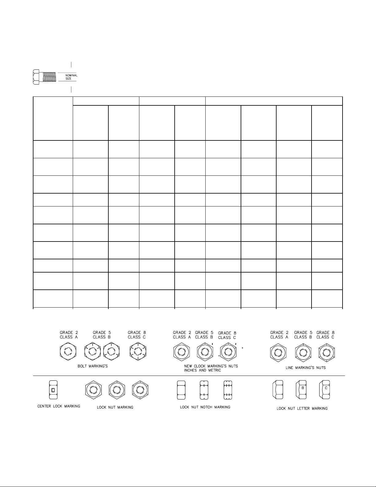
Torque Charts
Minimum Hardware Tightening Torques
In Foot Pounds (Newton-Metres) for Normal Assembly Applications
Inches Hardware and Lock Nuts
SAE Gr. 2 SAE Grade 5 SAE Grade 8 Lock Nuts
Nominal Unplated Plated Unplated Plated Unplated Plated Grade Grade
Size or W/ZnCr or W/ZnCr or W/ZnCr W/Gr.5 W/Gr.8
Plated Plated Plated Bolt Bolt
Silver Gold Silver Gold Silver Gold
1/4 55* (6.2) 72* (8.1) 86* (9.7) 112* (13) 121* (14) 157* (18) 61* (6..9) 86* (9.8)
5/16 115* (13) 149* (17) 178* (20) 229* (26) 250* (28) 324* (37) 125* (14) 176* (20)
3/8 17 (23) 22 (30) 26 (35) 34 (46) 37 (50) 48 (65) 19 (26) 26 (35)
7/16 27 (37) 35 (47) 42 (57) 54 (73) 59 (80) 77 (104) 30 (41) 42 (57)
1/2 42 (57) 54 (73) 64 (87) 83 (113) 91 (123) 117 (159) 45 (61) 64 (88)
9/16 60 (81) 77 (104) 92 (125) 120 (163) 130 (176) 169 (229) 65 (88) 92 (125)
5/8 83 (112) 107 (145) 128 (174) 165 (224) 180 (244) 233 (316) 90 (122) 127 (172)
3/4 146 (198) 189 (256) 226 (306) 293 (397) 319 (432) 413 (560) 160 (217) 226 (306)
7/8 142 (193) 183 (248) 365 (495) 473 (641) 515 (698) 667 (904) 258 (350) 364 (494)
1 213 (289) 275 (373) 547 (742) 708 (960) 773 (1048) 1000 (1356) 386 (523) 545 (739)
N14809 1/01
12
Page 23
Owner’s Manual (Snowblower)
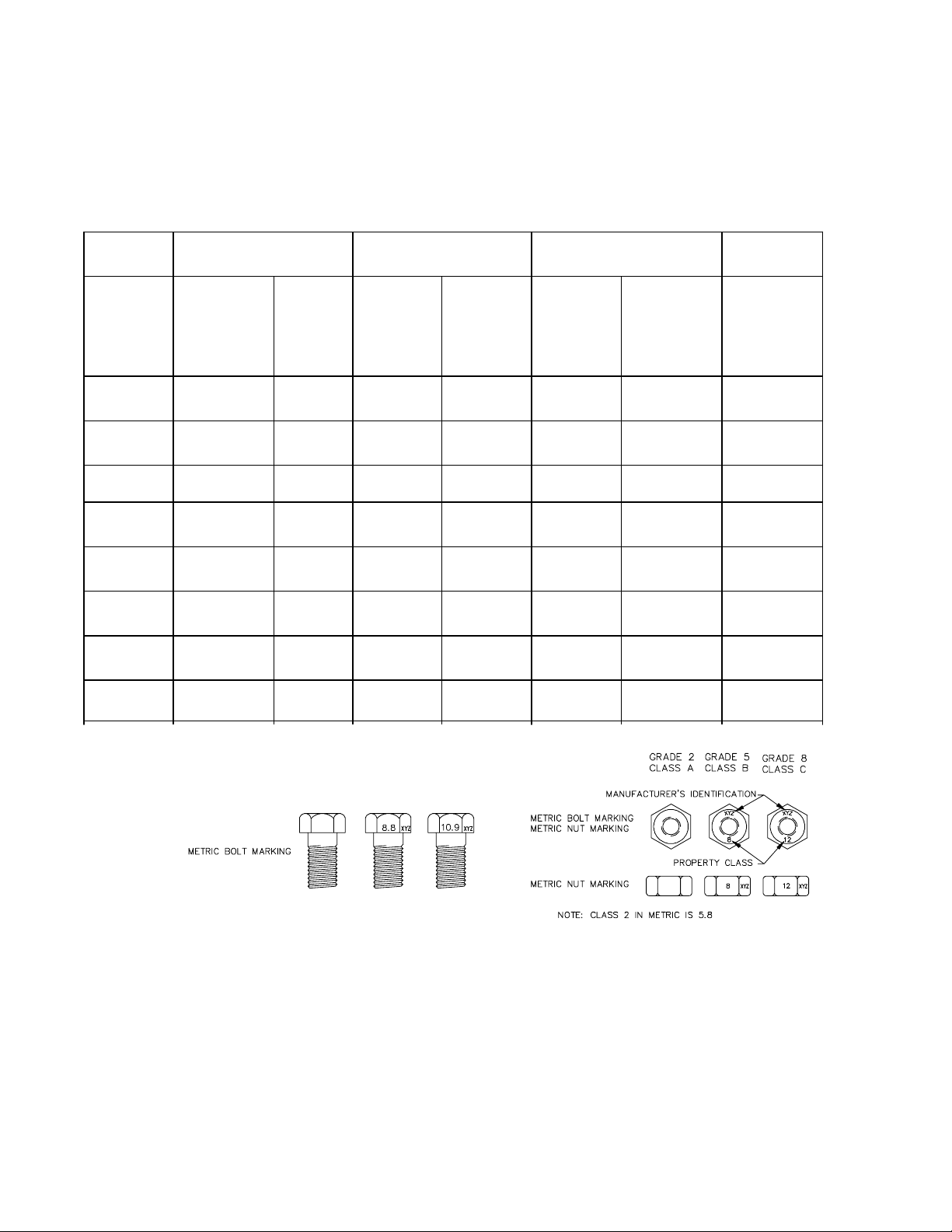
Torque Charts
Minimum Hardware Tightening Torque
Inch Pounds for Normal Assembly Applications
Metric Hardware and Lock Nuts
Class 5.8 Class 8.8 Class 10.9 Lock Nuts
Nominal Unplated Plated Unplated Plated Unplated Plated Class 8
Size or W/ZnCr or W/ZnCr or W/ZnCr W/CL.8.8
Plated Plated Plated Bolt
Silver Gold Silver Gold Silver Gold
M4 15* (107) 19* (2.2) 23* (2.6) 30* (3.4) 33* (3.7) 42* (4.8) 16* (1.8)
M6 51* (5.8) 67* (7.6) 79* (8.9) 102* (12) 115* (13) 150* (17) 56* (6.3)
M8 124* (14) 159* (18) 195* (22) 248* (28) 274* (31) 354* (40) 133* (15)
M10 21 (28) 27 (36) 32 (43) 41 (56) 45 (61) 58 (79) 22 (30)
M12 36 (49) 46 (63) 55 (750 72 (97) 79 (107) 102 (138) 39 (53)
M16 89 (121) 117 (158) 137 (186) 177 (240) 196 (266) 254 (344) 97 (131)
M20 175 (237) 226 (307) 277 (375) 358 (485) 383 (519) 495 (671) 195 (265)
M24 303 (411) 392 (531) 478 9648) 619 (839) 662 (897) 855 (1160) 338 (458)
N14809 1/01
13
Page 24

Page 25

Section
4
Service Parts
Page 26

Page 27

Owner’s Manual (Snowblower)
Service Parts
Ordering Service Parts:
To assist our customer service department in providing you with the correct replacement parts promptly and
accurately, follow the ordering instructions as listed below.
1. Order replacement parts by providing the following information:
A) Snowblower serial number – Refer to serial number plate, which also includes the model
number, located on center top of body (1” down). Or if the
plate is missing, check the top flange of the gearbox mounting
plate (serial number is stamped into the flange). Refer to page 16
for decal locations and additional service information.
B) Part description - Illustration drawings are provided to assist in identifying the
parts by description and part numbers. Use this information to
insure that correct service parts are ordered and sent to you.
C) Quantities - Order the exact number of parts required, do not order by
“sets”.
D) Shipping instructions - Give company/customer name, shipping point or will call and
mailing addresses notification if different than shipping point.
State whether freight, express, parcel or other handling is
desired. Confirm telephone orders in writing.
2. Inspection of parts when received is important. Damages or shortages should be brought to the attention of
the carrier at the time the parts are accepted. Shipper’s responsibilities cease upon delivery of shipment, in
good order, to the customer.
Return Policy:
Return of parts for either warranty or incorrect parts received, must have a “Return of Materials Authorization”
(RMA) number. Call Loftness Specialized Equipment, Inc. service department for this return number. To receive
this number, you will need your “Sales Order, Invoice and Part Numbers” with quantities of parts to be
returned. Credit information and shipping instructions will be given to you when you have received your “RMA”
number. Be sure to place this number on the outside of the shipping package and on any documents placed
inside.
Illustrated Parts Listings:
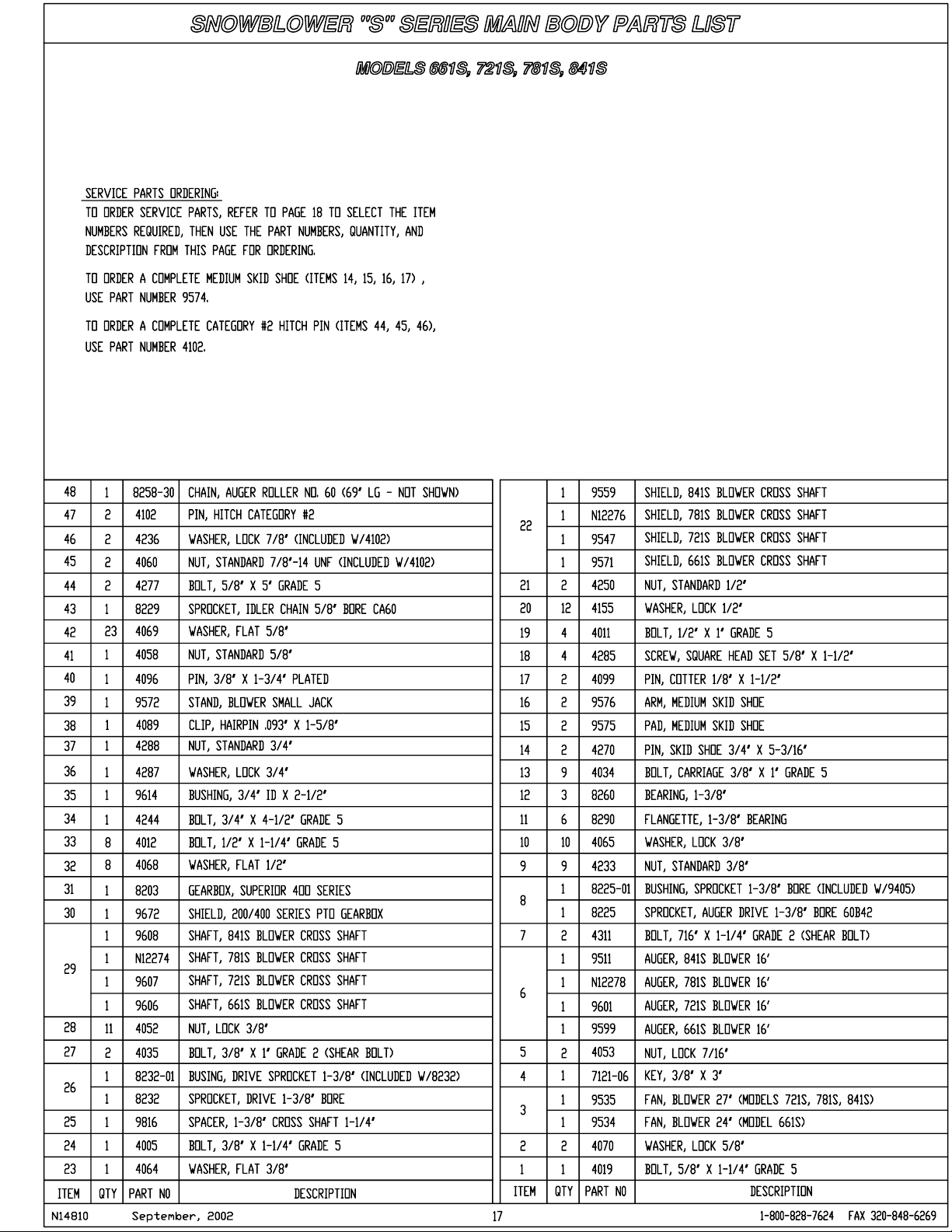
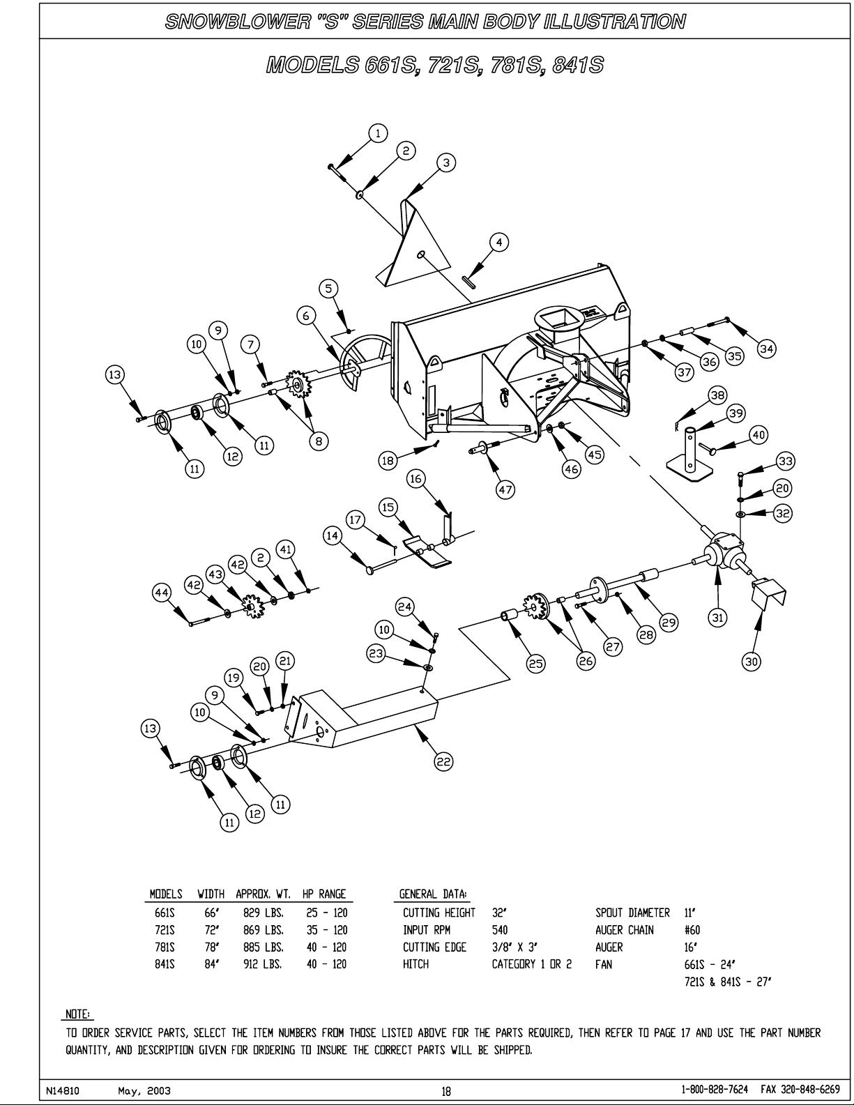
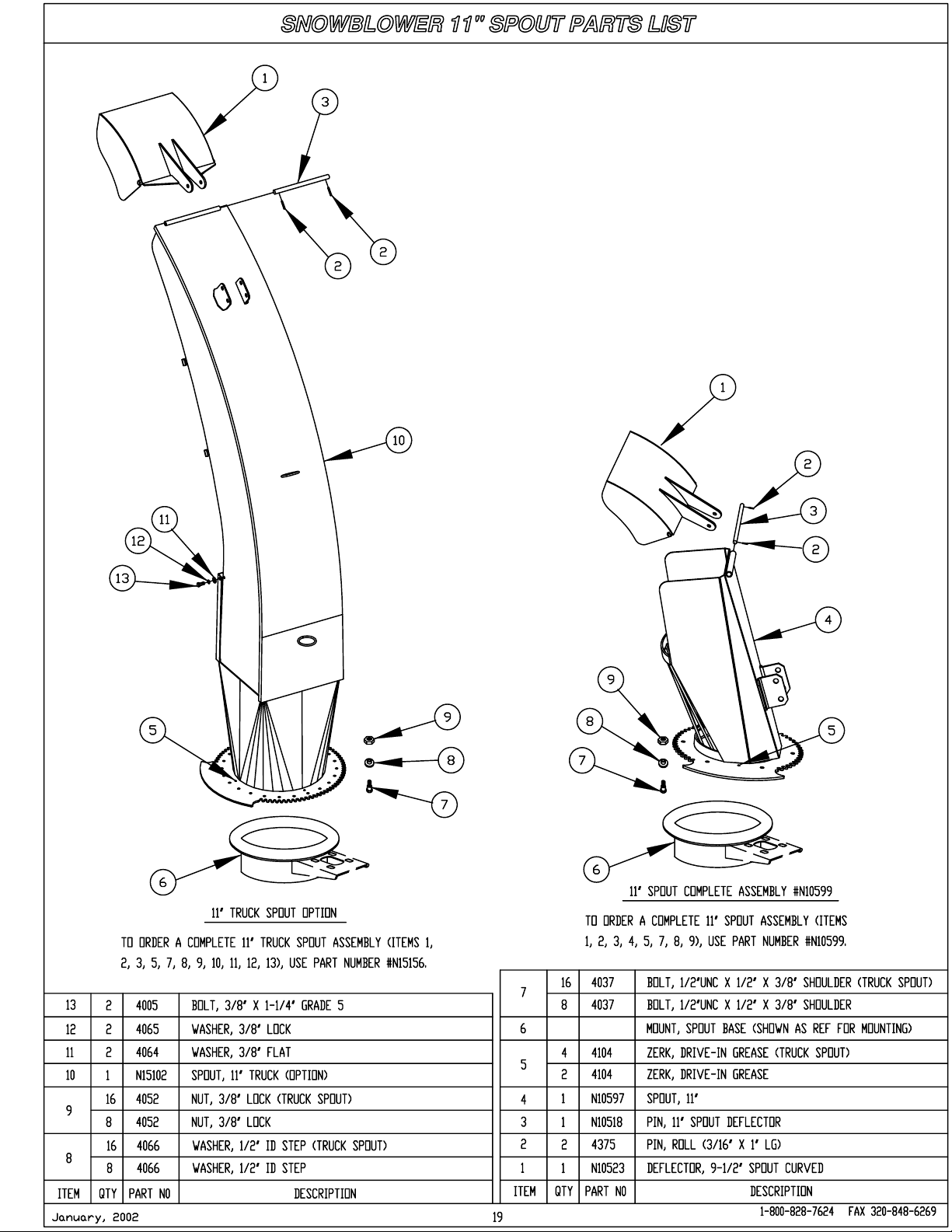
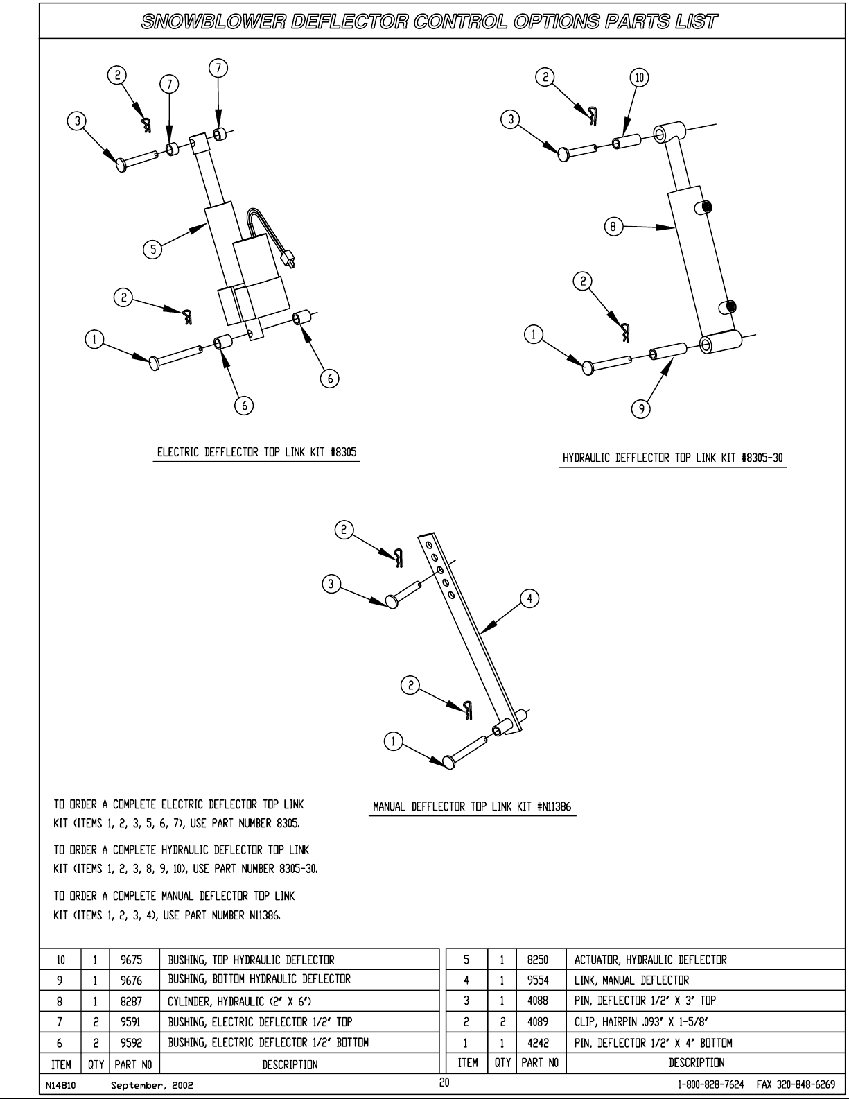
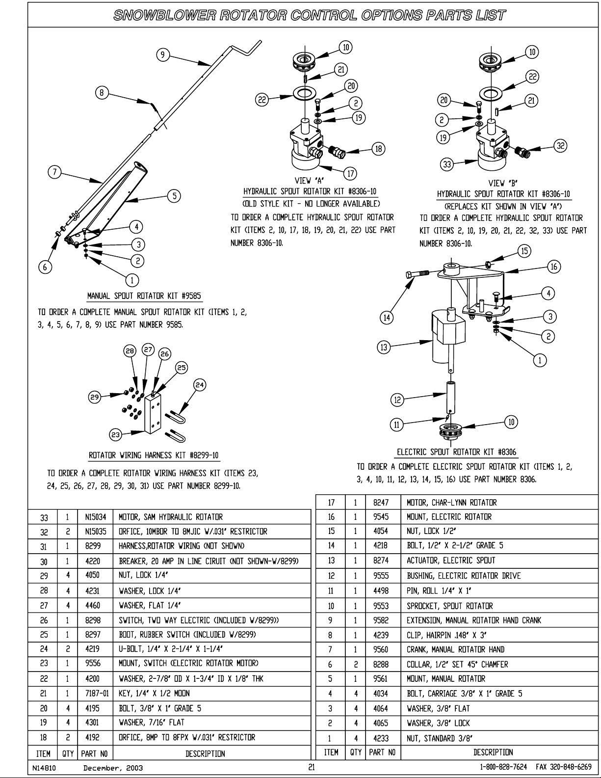
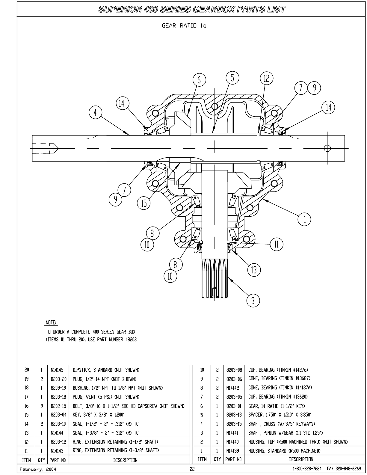
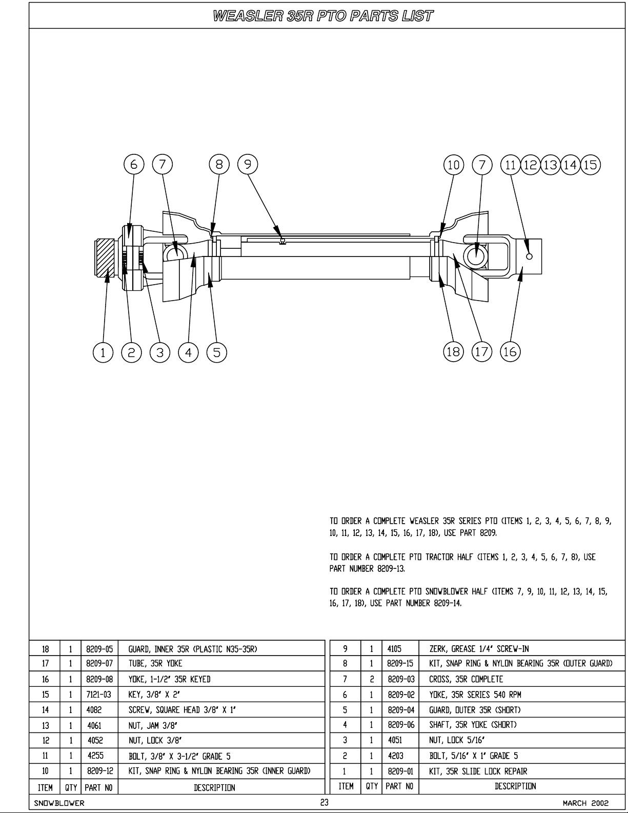
Illustrated parts drawings are included in this section, starting with page 17 that will assist you in identifying your
snowblower and the parts available for service. These pages include part numbers, descriptions and quantities
required for the various sizes of snowblowers. Include this information on your purchase orders to insure
correct receiving of replacement parts.
N14810 September, 2002
14
Page 28
Owner’s Manual (Snowblower)
Service Parts Continued
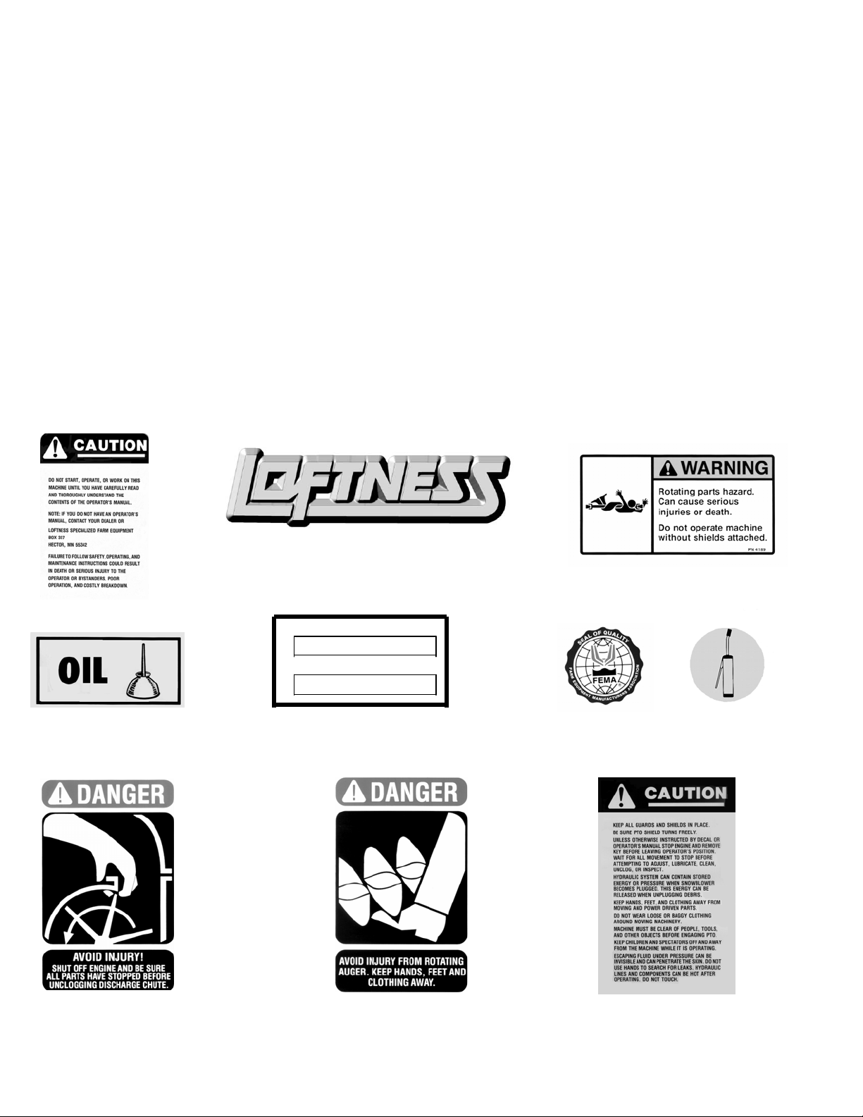
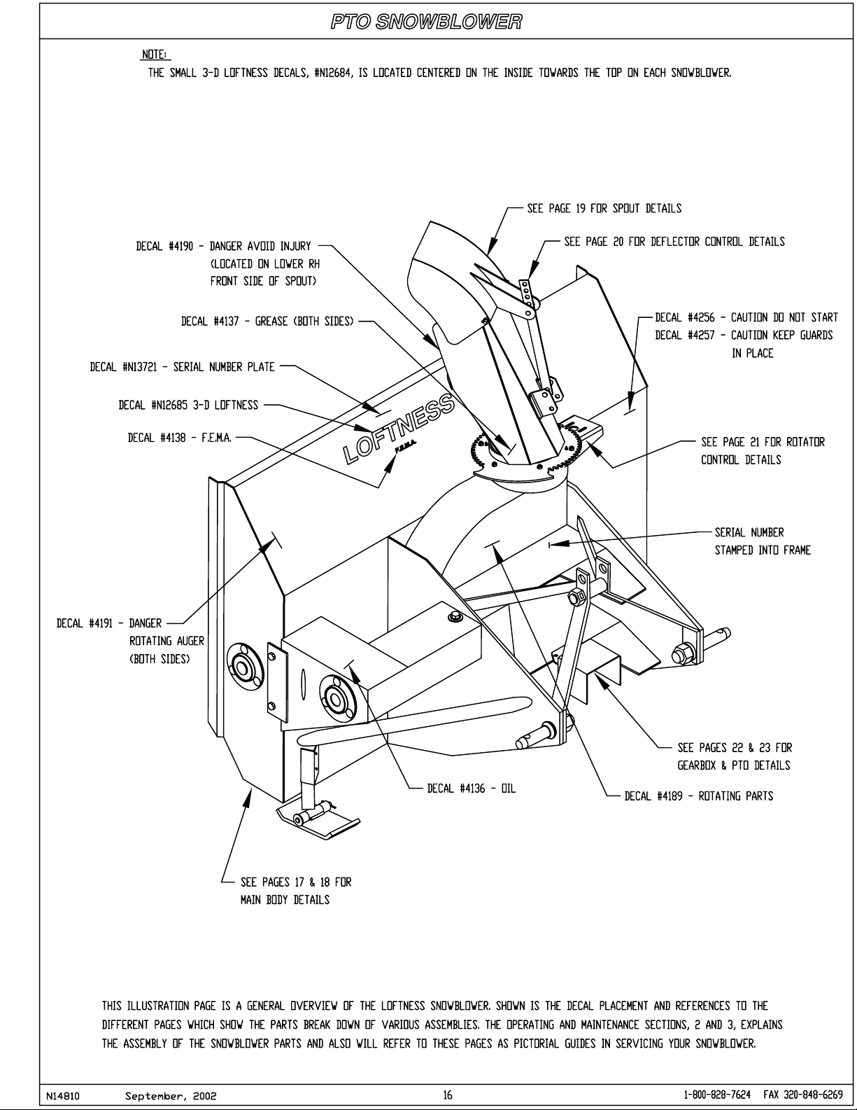
Safety and Operational Decals:
The following decals are placed in strategic positions on the unit to provide the operator with a continual
reminder of the safe operating practices. If they become damaged or lost, replace them immediately.
Replacement of Decals:
Surface must be free from dirt, dust, grease and other foreign material before applying the new decal. Refer to
illustration drawing on page 16 for placement of below listed decals:
4136 Oil – (1) required 4256 Caution – Do Not Start – (1) required
4137 Grease – (2) required 4257 Caution – Keep Guards – (1) required
4138 F.E.M.A. – (1) required N12684 Small 3D Loftness – (1) required
4189 Warning – Rotating Parts - (1) required N12685 Medium 3D – ((1) required
4190 Danger – Avoid Injury – (2) required N13721 Model & Serial Number tag – (1) required
4191 Danger – Keep Hands Away – (2) required
4189
4256
Model Number
Serial Number
4136
4190
N12684, N12685
N13721
4191
4138 4137
4257
N14810 September, 2002
15
Page 29
Page 30
Page 31
Page 32
Page 33
Page 34
Page 35
Page 36
 Loading...