

Page 1

Accessori Elettrici
Electric Accessories
Via Philips, 5 - 20052 Monza (MB) (Italy)
www.lofrans.com - e-mail: contact@lofrans.com
j^ab=fk=fq^iv
MANUALE DI INSTALLAZIONE E D’USO - INSTALLATION AND USER’S MANUAL
MANUEL D’INSTALLATION ED D’UTILISATION - MANUAL DE INSTALACIÓN Y USO
INSTALLATION UND BEDIENUNG
CONSERVARE QUESTO MANUALE A BORDO
STORE THIS MANUAL ON BOARD
CONSERVER CE MANUEL À BORD
DIESES HANDBUCH AN BORD AUFBEWAHREN
GUARDAR ESTE MANUAL A BORDO
2
Years Limited
Warranty
Iris
UK
IT
FR
DE
ES
Page 2

2
IRIS
Dear Customer,
Thank you for choosing a Lofrans product. Lofrans is a leader company in the production and worldwide distribution of nautical systems
manufactured according to the most modern technologies, in compliance with international regulation requirements and the most
important certifying bodies. All our products are manufactured with excellent materials suited for operations in marine environments and
are subject to continuous checks to improve the qualitative levels and make them without any manufacturing defects. Together with such
requirements, Lofrans anchor windlasses are a synthesis of reliability and efciency, by guaranteeing the maximum performances during
each phase of mooring, even in the most difcult. With a Lofrans product, years of reliable operations are guaranteed.
Lofrans declines any liability for possible inaccuracies due to print errors in this manual and reserves the right to introduce any changes
deemed appropriate.
For this reason, Lofrans does not guarantee the accuracy of the manual after the date of issue and declines all liability for possible errors
and omissions.
1 INTRODUCTION 3
1.1 Purpose of the manual 3
1.2 Assistance 3
1.3 Receipt and storage 3
2 INSTALLATION 3
2.1 Contents of the package 3
2.2 Recommended accessories 3
2.3 Installing the magnet on the anchor windlass 3
2.4 Installing the magnetic sensor for
vertical shaft anchor windlasses 4
2.5 Installing the magnetic sensor for
horizontal shaft anchor windlasses 4
2.6 Installing the chain counter 4-5
3 ELECTRICAL SYSTEM 5
4 TECHNICAL DATA 5
5 MENU 5
5.1 Starting up 5-6
5.2 Chain counter setting menu 6
5.3 Measurement menu 6
5.4 Alarm and functions menu 7
5.5 Settings menu 7
5.6 Language menu 7
5.7 Sensor calibration menu 8
Lofrans©copyright, 2015. All rights reserved.
PRODUCT COMPLIANT WITH CE REGULATIONS
TABLE OF CONTENTS
5.8 Table 1 - Standard and Project X. series sensor 8
5.9 Table 2 - 1000 – 1500 – 2000W
Project series sensor 9
5.10 Check menu 9
6 USΕ 10
6.1 Measurement reset 10
7 TROUBLESHOOTING 10
8 WIRING DIAGRAM 10
9 WARRANTY CONDITIONS 11
Page 3

3
www.lofrans.com
UK
DANGER!
A warning such as this indicates the existence of a serious risk that has high probabilities to cause death or a serious accident if
appropriate precautions are not taken.
ATTENTION!
A warning such as this indicates a reference to the application of safety practices, or draws the attention on unsafe behaviours
that might cause personal injuries or damages to the boat.
1.1 Purpose of the manual
This manual will supply information on safety and correct use of the product. Follow these warnings carefully to avoid possible
accidents or damages.
2.1 Contents of the package
- chain counter, seal and closure cover;
10-pole male connector with crimp-type10
- male contacts;
- magnetic sensor;
- support kit (support for the vertical shaft anchor windlass
sensor, supporting base, 2 fastening screws, O-ring);
- magnet;
- horizontal shaft anchor windlass sensor support;
- instructions for use.
1.2 Assistance
The Lofrans products are backed throughout the world by a network of authorised distributors and assistance. In case of need,
please contact your local Lofrans distributor. Details on website www.lofrans.com
2.2 Recommended accessories
Use exclusively original Lofrans accessories and spare parts, designed and manufactured to ensure performances, duration and for
keeping valid the warranty. For information on available spare parts, contact your local reseller or visit website www.lofrans.com
1.3 Receipt and Storage
Upon receipt of the package, verify the integrity of packing. Should it be necessary to store the product for a prolonged period,
keep it in a dry and protected place.
1 INTRODUCTION
2 INSTALLATION
2.3 Installing the magnet on the anchor windlass
On a few models of anchor windlass the sensor and the magnet are
already installed (chain counter setting).Therefore, the operations
described below are not necessary.
1. A hole having a diameter of 6.5 mm (~1/4”) and depth of 8 mm (5/16”) must
be drilled on a tooth of the gipsy, in a place outside the chain’s path.
2. In the case of vertical shaft anchor windlasses (see Fig.1B), drill the hole
in the lower circumference of the gipsy.
3. In the case of horizontal shaft anchor windlasses (see Fig.2B), drill the hole
in the outer circumference of the gipsy.
4. Also make sure that the protruding part of the magnet will not collide with
the base or sensor during rotation of the gipsy.
Insert the metal part of the magnet in the hole, allowing the protected part
to protrude by about 2 mm. Fix it in place using an adhesive for metals (two
component epoxy glue) or silicone. The glue used must be able to withstand
a marine environment.
Fig. 1B
Fig. 2B
Page 4

4
IRIS
2.4 Installing the magnetic sensor for vertical shaft anchor windlasses
Drill a 4 mm (~3/16”) hole in the cover through which to thread the sensor cable.
Fasten Part A of the support with the two screws provided, after having positioned the O-ring in the lower part of the support.
Fit Part B with the magnetic sensor on support A and adjust its height until it is aligned with the magnet fastened on the gipsy.
Bring the sensor to a distance of about 3 mm (~1/8”) from the magnet and secure it in place by tightening screw G1.
Then tighten screw G2.
OR
A
B
G1
G2
2.5 Installing the magnetic sensor for horizontal shaft anchor windlasses
(see Fig. 2A – 2B – 2C)
Drill a 4 mm (~3/16”) hole in the cover through which to thread the sensor cable. Fasten Part A of the support with the two screws
provided, after having positioned the O-ring in the lower part of the support. Cut Part C to measure using a hacksaw. The sensor must be
positioned at a distance of about 3 mm (~1/8”) from the magnet. Fit Part C with the magnetic sensor on support A and x it in place using
an adhesive for plastic (two-component epoxy glue) or silicone. Using the same glue, attach the sensor to Part C.
Part.C
Part.A
magnetic sensor
sensore magnetico
Fi g. 2A
Fi g. 2B
Fig. 2C
sensor cable
cavo sensore
2.6 Installing the chain counter
(see connection diagram)
The chain counter must be positioned so that the display will be easy to read. It should not be exposed to direct sunlight.
The rear part of the instrument must be protected from contact with water or moisture. The instrument may be fastened to dashboards of
any thickness. The screws used for clamping must be of the selfthreaded kind and with a diameter of 3.5 mm (~9/64”) and a maximum
length of 10 mm plus the thickness of the dashboard. In the part to the rear of the dashboard there must be minimum clearance of 35 mm
(1” 3/8) and there must also be adequate access to perform installation and maintenance work. On the dashboard make a hole with a
diameter of 30 mm (~ 1” 3/16), as indicated, and 4 holes with diameters of 4 mm (~5/32”) for the chain counter clamping screws. Use
cutting nippers to cut the three pins on the back of the instrument, position the chain counter and fasten it to the dashboard by tightening
the four screws. If the dashboard already has a hole with a 54 mm (2”1/8) diameter, it is not necessary to cut the pins on the back. The
seal must be positioned between the chain counter and the dashboard.
ALWAYS DISCONNECT THE BATTERY PRIOR TO INSTALLATION
Page 5

5
www.lofrans.com
UK
For instructions on making electrical connections, see the attached diagram. The wires must have a minimum cross section size
of 1.5 mm². Install a 4 A (ampere) fast safety fuse on the + wire of the battery. Do not use the voltage generated by the engine battery
set to provide power.
The instrument complies with EMC standards (EN55022) and must be positioned at a distance of:
- 30 cm (~1 Ft) from the compass; -50 cm (~1.5 Ft) from radio equipment;
- 2 metres (~6.5 Ft) from radio transmitter equipment; -2 metres (~6.5 Ft) from the radar beam.
3 ELECTRICAL SYSTEM
10 -POLE REAR CONNECTOR
PIN SIGNAL
1 + battery
2
3 - battery
4
5
6 UP command
7 DOWN command
8
9
10 Magnetic sensor
4 TECHNICAL DATA
Receiver
Power supply from 12 to 24 Vdc
No-load current intake min. 5 mA – max 40 mA
Protection rating IP67*
Operative temperature -10 : +60
Graphic display 128 x 64 pixels
Max. chain length 999 metres – 999 feet
Size (mm) 110 x 105 x 23**
Net Weight (g) 160**
*Excluding cable connection zone
** without protective cover
5.1 Starting up
The chain counter features a graphic display and three keys: (ON), (UP) and
(DOWN). There is also a buzzer that indicates the pressing of the keys or attracts
the user’s attention in particular conditions (alarm triggering). The ON key switches on
the display and enables the other two keys. It must be used to access the parameter
setting menus. For selecting the parameters to be modied and to conrm the values set.
The display backlight will switch off 30 seconds after the last command given (adjustable
default time – see “BkLight Time”).
The UP key commands the hoisting of the anchor and the DOWN key casts it. When the
key is released, the action is stopped. During parameter setting, the two keys allow the
User to move around the menu and vary parameter values.
5 MENU
Page 6

6
IRIS
When switched on, the instrument will make a beep and the following page will appear for a few seconds:
Once the initialisation procedure is complete, the main page will appear.
Where:
STATUS: indicates the status of the instrument and any failure.
SPEED’: indicates the chain speed during hoisting or lowering in meters per minute or feet per minute.
COUNT: indicates the measurement of the chain lowered (in metres or feet).
MONITORING: indicates the power supply voltage of the instrument and the power supply voltage of the boat.
ICONS: this is the part of the display bearing the icons that indicate the hoisting or casting of the anchor and any failure.
When the instrument is turned on for the rst time, it will set up as programmed in the factory (see table).
V=11.6 Vdc
Hold down the (ON) key for six seconds to
access the instrument setting menu. The following
page will appear on the display:
Use the (DOWN) and (UP) keys to
move around the menu options.
Once you are positioned on the item to be modied press the (ON) key to conrm your choice.
Use the (DOWN) or (UP) keys to move from one parameter to another.
Once one is positioned on the parameter press the (ON) key to enable modication.
According to the type of parameter, using the (DOWN) and (UP) keys it is possible to
reduce/increase the value of the same or disable/enable the function.
Once the modication has been performed, press the (ON) key to conrm.
Using the (DOWN) key go to the Exit option and press the (ON) key again to return to
the setting menu. The same procedure must be used to return to the main page.
5.2 Chain counter setting menu
Menu
Measure
Alarms &Function
Settings
Language
S ensor Calibration
5.3 Measurement menu
Use the (DOWN) or (UP) key to move around the parameters
Reset Measurement
Resets the chain measurement value (0.0).
Select with
= Yes = No
Conrm with
Units
Selects the unit of measurement:
Feet/ inches
Metres / centimetres
Select with
= Feet = Metres
Conrm with
Exit
To return to the settings menu.
Conrm with
Measure
ResetMeasure No
Unit
sF
eet
Exit
Page 7

7
www.lofrans.com
UK
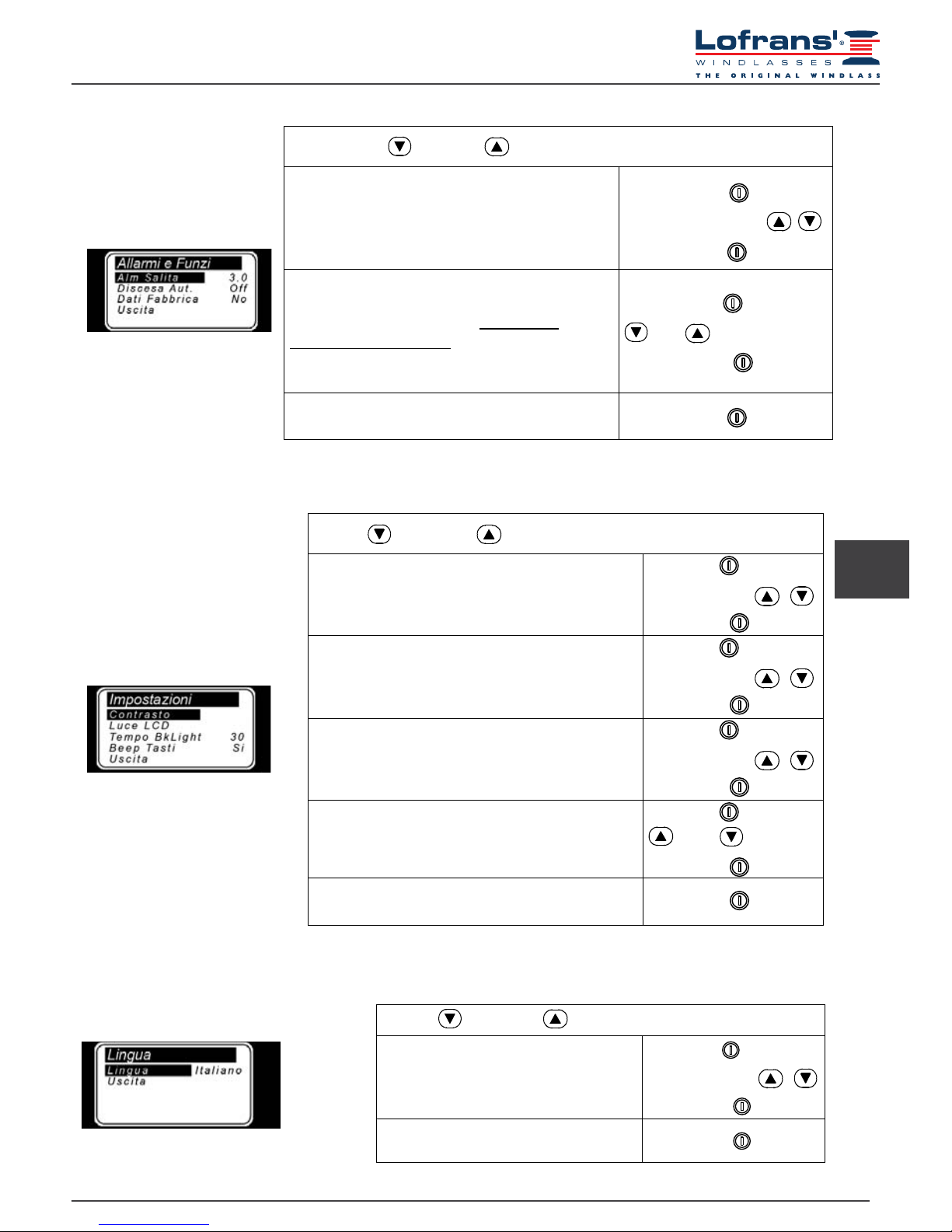
5.5 Settings menu
Use the (DOWN) or (UP) key to move around the parameters
Contrast
By enabling this function it is possible to start
the display contrast programming procedure.
Select with
Select value with
Conrm with
Back Light
This function allows the user to set the backlight on
time during which the display remains lit after the last
command given (default value 30 seconds).
Select with
Select value with
Conrm with
Light Time
By enabling this function it is possible to start the
display luminous intensity programming procedure.
Select with
Select value with
Conrm with
Keyboard Beep
This function allows the user to enable or disable the
buzzer (emitted each time a key is pressed).
Select with
= Yes = No
Conrm with
Exit
To return to the settings menu.
Conrm with
5.4 Alarm and functions menu
Use the (DOWN) or (UP) key to move around the parameters
Up Alarm
It is possible to enable the function and establish the
height at which the anchor-winch stops; after which it
is only possible to give pulsed commands.
Settable values: 1.0 - 1.5 - 2.0…5.0 (metres or feet).
Select with
Select value with
Conrm with
Load Default
This function allows the User to revert to the original
factory default settings, thus erasing all settings
memorised.
This command must only be used in the event of
programming errors.
Select with
= Yes = No
Conrm with
Exit
To return to the settings menu.
Conrm with
5.6 Language menu
Use the (DOWN) or (UP) key to move around the parameters
Language
The user may select the display language:
Italian, English, French, German,
Spanish, Greek
Select with
Select value with
Conrm with
Exit
To return to the settings menu.
Conrm with
Language
Langu age English
Exit
Page 8

8
IRIS
5.7 Sensor calibration menu
Once the “Sensor Detection” function has recognised a “Standard” type sensor instead of a “Project” sensor, when
the “Sensor Calibrat.” menu is entered again, the menu options will “congure” themselves according to the sensor
detected.
Standard and X.. Project series sensor menu
(magnet and sensor placed on barbotin)
1000 – 1500 –2000 W Project series sensor menu
(magnet and sensor placed on motor)
Barbotin Circumference
In this row the user must enter the circumference of the
gipsy (in centimetres or inches).
Use the Table 1 provided to calculate the circumference.
Settable values: centimetres or inches.
Default value, 33 cm.
Reduction Factor
In this row the user must enter the reduction factor.
See next Table 2 for the correct value to be entered
Default value, 57.
Select with
Select value with
Conrm with
Exit
To return to the settings menu.
Conrm with
Use the (DOWN) or (UP) key to move around the parameters
Sensor Selection
Select with
Press or
Conrm with
STD
PROJ
Sensor Selection
5.8 Table 1 - Standard and Project X.. series sensor
(magnet and sensor placed on barbotin)
Chain type Number of recesses Gipsy Circumference (cm) Gipsy Circumference inches)
6 mm 9 34 13
7 mm 6 25 9
8 mm
6 28 11
7 33* 13
8 38 15
10 mm
5 31 12
6 36 14
12 mm
5 36 14
6 43 17
13 mm 6 46 18
14 mm 5 42 16
3/8” BBB 7 38 15
3/8” HT 6 37 14
5/16” HT 7 36 14
1/2” BBB 6 40 16
1/2” HT 5 40 16
* factory setting of instrument
Page 9

9
www.lofrans.com
5.9 Table 2 - 1000 – 1500 – 2000W Project series sensor
(magnet and sensor placed on motor)
* factory setting of instrument
Type
Gipsy Circumf.
(cm)
Reduction
ratio
Number of
recesses
Chain type
(mm-inches)
Reduction
Factor
Project 1000
30 1:52 6 8-5/16”HT
57*
30 1:52 5 10 DIN 766
31 1:52 5 10 ISO-3/8”HT 59
34 1:52 9 6 65
Project 1500
30 1:70 6 8-5/16”HT 43
30 1:70 5 10 DIN 766 43
31 1:70 5 10 ISO-3/8”HT 44
36 1:70 5
12 ISO-13 DIN 766-
7/16”HT
51
Project 2000
39 1:75 6 3/8”HT 52
40 1:75 6 3/8”Proof Coil 53
41 1:75 6 10 DIN 766-3/8”BBB 54
44 1:75 7 10 ISO 58
45 1:75 5 14 ISO 60
46 1:75 6 12 ISO-13 DIN 766 61
47 1:75 5 13 DIN 764 63
5.10 Check menu
Tests
Software Version
Operat. Time
Sensor Test
Exit
LCD Test
3.0
0
Use the (DOWN) or (UP) key to move around the parameters
Software Version
Indicates the version of the software installed.
Operation Time
Indicates the time the instrument operates
Select with
Conrm with
LCD Test
This function switches on all the display’s pixels
thus making it possible to perform a check on
them.
Select with
Conrm with
Exit
To return to the settings menu.
Conrm with
Sensor Test
Sensor Test
UK
Sensor Test
The purpose of this function is to check the state
of the sensor:
contact open
contact closed
Page 10

10
IRIS
6.1 Measurement reset
Press the (ON) key to activate controls and to switch on the display lighting. The
display lighting switches off 60 seconds after the last command given (adjustable
default time – see “BkLight Time”).
To reset the measurement count
simultaneously press the (ON) and the
(UP) keys for at least three seconds.
Measurement reset may also be performed
in the Measurement menu by selecting
“Yes” in the Reset Measure row.
When any key is released (UP or DOWN) the corresponding action is stopped.
Press key (UP) to control the anchor ascending
Press key (DOWN) to cast anchor
V=11.6 Vdc
V=11.6 Vdc
6 USE
Measure
ResetMeasure No
Unit
sF
eet
Off
Exit
7 TROUBLESHOOTING
FAULT CAUSE CORRECTIVE ACTION
Though UP or DOWN keys
are pressed, the instrument
doesn’t receive any signal from
the magnetic sensor for more
than 5 seconds.
Check the sensor electric connections.
Check if sensor operates properly.
If not, replace it.
Check the position of sensor and magnet on
gipsy and their distance (3 mm).
Check the operation of electric
installation or anchor windlass.
The instrument’s power
supply voltage is lower than10Vdc.
Verify the battery charge or
operation of the electrics system.
V=11.6 Vdc
V= 7.9 Vdc
8 WIRING DIAGRAM
Page 11

11
www.lofrans.com
9 WARRANTY CONDITIONS
Lofrans warrants that in normal use and observing the maintenance schedules, the product is covered by warranty for a period of 3
years from the date of purchase by the original purchaser, without prejudice to the conditions, limitations and exceptions listed below.
Any product that proves defective in normal use during said period shall be repaired or replaced, as Lofrans chooses.
- Lofrans does not assume any responsibility for an incorrect choice of product made by the purchaser.
- The responsibility of Lofrans shall be limited to the repair or replacement of all parts of the product that originally present material and/
or manufacturing defects.
- Lofrans shall not in any way be liable for faults or any consequent damage originating from:
- use of the product in applications for which it was not designed;
- corrosion, degradation caused by ultraviolet rays and wear;
- failure to follow the maintenance schedule;
- incorrect or unsuitable product installation;
- any modication or alteration of the product;
- conditions of use exceeding the product specications.
- The warranty does not cover the additional costs borne for interventions, removal, transport and installation of the product;
- The warranty is cancelled if maintenance is carried out by people not authorised by Lofrans.
- Lofrans products are designed to be used only in the marine environment. Lofrans does not assume any
responsibility deriving from other uses.
- Lofrans reserves the right to not acknowledge this warranty if the electromechanical products are operated by unsuited
electrical accessories and/or in the case of failure to install an appropriate overload cutout switch on the electric power line.
9.1 Conditions and limitations
Coverage under warranty is limited to a period of 2 years from the date of purchase by the original purchaser for:
- Electrical or electronic control equipment
- Control box and contactors
- Overload cutout switches
Coverage under warranty is limited to a period of 1 year from the date of purchase by the original purchaser for:
- Electric motors
- Electrical boards
- Gaskets and seals
- All the products used on charter boats.
This warranty does not cover any loss or damage caused to the purchaser by the ascertained non-conformity of the product, except for
the case of fraud or gross negligence of Lofrans declared with a court ruling.
Some states and countries do not allow the exclusion or limitation of incidental or consequential damages, so the above-stated
limitations or exclusions might not be applicable.
The warranty application must be notied to Lofrans or to an authorised Lofrans service centre in writing and sent by fax or
email,attaching the product serial number.
If Lofrans does not give instructions to the contrary, any product subject to a warranty application must be returned directly
to Lofrans - via Philips 5 Monza (MB) 20900 Italy.
If any clause of this warranty is invalidated by a judge or other competent authority, the validity of the remaining clauses of this warranty
and the rest of the clause in question will not be affected.
This warranty is governed by the laws and in conformity with Italian laws.
The Court of Milan has jurisdiction over all disputes.
9.2 Exceptions
9.3 Liability
9.4 Procedure
9.5 Termination clause
9.6 Conformity
UK
Page 12

12
IRIS
Gentile cliente,
grazie per aver scelto un prodotto Lofrans. Lofrans è una azienda leader nella produzione e distribuzione mondiale di impianti nautici
realizzati secondo le più moderne tecnologie, in conformità ai requisiti indicati dalle normative internazionali e dai più importanti enti
di certicazione. Tutti i nostri prodotti sono costruiti con ottimi materiali adatti al lavoro in ambiente marino e sono soggetti a continui
controlli per migliorare i livelli qualitativi e renderli privi di difetti di fabbricazione. Accanto a tali requisiti, i salpa ancora Lofrans sono una
sintesi di afdabilità ed efcienza, assicurando le massime prestazioni durante ogni fase dell’ormeggio, anche in quelle più difcili. Con
un prodotto Lofrans si è sicuri di anni di afdabile funzionamento.
Lofrans declina ogni responsabilità per eventuali inesattezze dovute a errori di stampa contenuti nel presente manuale e si riserva il
diritto di apportare tutte le modiche ritenute opportune.
Per tale motivo Lofrans non garantisce l’esattezza del manuale dopo la data di pubblicazione e declina ogni responsabilità per eventuali
errori ed omissioni.
1 INTRODUZIONE 13
1.1 Scopo del manuale 13
1.2 Assistenza 13
1.3 Ricevimento e stoccaggio 13
2 INSTALLAZIONE 13
2.1 Contenuto della confezione 13
2.2 Accessori consigliati 13
2.3 Installazione del magnete sul salpa ancora 13
2.4 Montaggio sensore magnetico per salpa ancora
ad asse verticale 14
2.5 Montaggio sensore magnetico per salpa ancora
ad asse orizzontale 14
2.6 Installazione contametri 14-15
3 IMPIANTO ELETTRICO 15
4 DATI TECNICI 15
5 MENU 15
5.1 Prima accensione 15-16
5.2 Menù impostazione contametri 16
5.3 Menù Misura 16
5.4 Menù Allarmi e Funzioni 17
5.5 Menù Impostazioni 17
5.6 Menù Lingua 17
5.7 Menù Calibrazione Sensore 18
© Copyright Lofrans, 2015. Tutti i diritti riservati.
PRODOTTO CONFORME ALLE NORMATIVE CE
INDICE
5.8 Tabella 1 - Sensore Standard e
Project serie X 18
5.9 Tabella 2 - Sensore Project serie
1000 – 1500 – 2000W 19
5.10 Menù Veriche 19
6 USO 20
6.1 Reset della misura 20
7 ANOMALIE FUNZIONAMENTO 20
8 SCHEMA DI COLLEGAMENTO 20
9 CONDIZIONI DI GARANZIA 21
9.1 Condizioni e limiti 21
9.2 Eccezioni 21
9.3 Responsabilità 21
9.4 Procedura 21
9.5 Clausola di cessazione 21
9.6 Conformità 21
Page 13

13
www.lofrans.com
PERICOLO!
Un avviso come questo indica l’esistenza di un grave rischio, che ha alte probabilità di causare morte o un grave infortunio, se non
vengono adottate le precauzioni appropriate.
ATTENZIONE!
Un avviso come questo indica un richiamo all’applicazione di pratiche di sicurezza, oppure richiama l’attenzione su comportamenti
poco sicuri che potrebbero causare infortuni personali o danni alla imbarcazione.
1.1 Scopo del manuale
Attraverso questo manuale verranno date informazioni relative alla sicurezza e al corretto utilizzo del prodotto.
Seguire attentamente queste avvertenze in modo da evitare possibili infortuni o danneggiamenti.
2.1 Contenuto della confezione
- contametri, guarnizione e coperchio di chiusura;
- connettore maschio a dieci poli con 10
contatti maschio a crimpare;
- sensore magnetico;
- kit supporto (supporto del sensore per salpa ancora ad asse
verticale, base di supporto, 2 viti di ssaggio, guarnizione OR);
- magnete;
- supporto sensore per salpa ancora ad asse orizzontale;
- istruzioni per l’uso.
1.2 Assistenza
I prodotti Lofrans sono supportati in tutto il mondo da una rete di distributori e assistenza autorizzati. In caso di necessità
contattare il distributore locale Lofrans. Dettagli sul sito www.lofrans.com
2.2 Recommended accessories
Utilizzare esclusivamente accessori e ricambi originali Lofrans, progettati e costruiti in modo da assicurare prestazioni, durata e
mantenere valida la garanzia. Per informazioni sui ricambi disponibili, rivolgersi al rivenditore locale o visitare il sito www.lofrans.com
1.3 Receipt and Storage
Al ricevimento della confezione, vericare l’integrità dell’imballo. In caso sia necessario immagazzinare il prodotto per un
periodo prolungato, mantenere in luogo asciutto e protetto.
1 INTRODUZIONE
2.3 Installazione del magnete sul salpa ancora
Su alcuni modelli di salpa ancora il sensore ed il magnete sono stati già
installati (predisposizione contametri) non è quindi necessario eseguire
le operazioni indicate di seguito.
1. Il foro da praticare su un dente del barbotin - del diametro di 6,5 mm (~1/4”)
e della profondità di 8 mm (5/16”) - deve trovarsi in una zona non interessata
dal passaggio della catena.
2. Per i salpa ancora ad asse verticale (vedi Fig. 1B) eseguire la foratura nella
circonferenza inferiore del barbotin.
3. Per i salpa ancora ad asse orizzontale (vedi Fig. 2B) eseguire la foratura
sulla circonferenza esterna del barbotin.
4. Vericare, inoltre, che la parte sporgente del magnete, durante la rotazione
del barbotin, non urti contro la base o il sensore. Inserire il magnete, nel
foro, dalla parte metallica lasciando sporgere la parte protetta di circa 2 mm.
Fissarlo utilizzando un collante per metalli (colla epossidica bi-componente)
o silicone. Il collante utilizzato deve essere resistente all’ambiente marino.
Fig. 1B
Fig. 2B
IT
2 INSTALLAZIONE
Page 14

14
IRIS
2.4 Montaggio sensore magnetico per salpa ancora ad asse verticale
Praticare nella coperta un foro del diametro di 4 mm (~3/16”) per il passaggio del cavo del sensore. Fissare il Part. A del supporto,
con le due viti a corredo, dopo avere posizionato nella parte inferiore dello stesso la guarnizione OR. Inserire il Part. B, con il sensore
magnetico, sul supporto A e regolarlo in altezza in modo che si trovi in asse con il magnete ssato sul barbotin. Avvicinare il sensore a
circa 3 mm (~1/8”) dal magnete e ssarlo serrando la vite G1. Serrare successivamente la vite G2.
OR
A
B
G1
G2
2.5 Montaggio sensore magnetico per salpa ancora ad asse orizzontale
(vedi Fig. 2A – 2B – 2C)
Praticare nella coperta un foro del diametro di 4 mm (~3/16”) per il passaggio del cavo del sensore. Fissare il Part. A del supporto, con le
due viti a corredo, dopo avere posizionato nella parte inferiore dello stesso la guarnizione OR. Tagliare, con un seghetto, a misura il Part.
C. Il sensore deve essere posizionato a circa 3 mm (~1/8”) dal magnete. Inserire il Part. C, con il sensore magnetico, sul supporto A e
ssarlo utilizzando un collante per materiali plastici (colla epossidica bi-componente) o silicone. Fissare, con lo stesso collante, il sensore
al Part. C
Part.C
Part.A
magnetic sensor
sensore magnetico
Fi g. 2A
Fi g. 2B
Fig. 2C
sensor cable
cavo sensore
2.6 Installazione contametri
(vedi schema elettrico)
Il contametri deve essere posizionato in modo che il display sia facilmente leggibile e non esposto ai raggi solari. La parte posteriore del
contametri deve essere protetta dal contatto di acqua o di umidità. Lo strumento può essere ssato su plance di qualsiasi spessore. Le
viti per il ssaggio devono essere autolettanti con un diametro di 3,5 mm (~9/64”) e aventi una lunghezza massima pari a 10 mm più lo
spessore della plancia. Nella parte posteriore, alla plancia, vi deve essere uno spazio minimo pari a 35 mm (~1”3/8). Inoltre, deve essere
presente un accesso per l’installazione e la manutenzione. Sulla plancia praticare un foro del diametro di 30 mm (~ 1” 3/16), come
indicato, e 4 fori da 4 mm (~5/32”) per le viti di ssaggio del contametri. Tagliare con un tronchese i tre piolini posti sul lato posteriore
dello strumento, posizionare il contametri e ssarlo alla plancia serrando le quattro viti. Qualora sulla plancia sia già presente un foro da
54 mm (2”1/8) non occorre tagliare i piolini posteriori. La guarnizione deve essere interposta tra il contametri e la plancia
STACCARE SEMPRE LA BATTERIA PRIMA DI PROCEDERE L’INSTALLAZIONE.
Page 15

15
www.lofrans.com
Per il collegamento elettrico seguire le indicazioni dello schema allegato. I cavi devono avere una sezione minima di 1,5 mm².
Montare un fusibile di protezione rapido da 4 A (ampere) sul cavo + della batteria. Non utilizzare per l’alimentazione la tensione
proveniente dal gruppo batterie motori. Lo strumento risponde agli standard EMC (EN55022) e deve essere posizionato a una
distanza di:
- 30 cm (~1 Ft) dalla bussola; -50 cm (~1,5 Ft) da apparecchi radio;
- 2 metri (~6,5 Ft) da apparecchi radiotrasmettenti; -2 metri (~6,5 Ft) dal fascio radar.
3 IMPIANTO ELETTRICO
10 -POLE REAR CONNECTOR
PIN SIGNAL
1 + battery
2
3 - battery
4
5
6 UP command
7 DOWN command
8
9
10 Magnetic sensor
4 DATI TECNICI
Receiver
Power supply from 12 to 24 Vdc
No-load current intake min. 5 mA – max 40 mA
Protection rating IP67*
Operative temperature -10 : +60
Graphic display 128 x 64 pixels
Max. chain length 999 metres – 999 feet
Size (mm) 110 x 105 x 23**
Net Weight (g) 160**
*Excluding cable connection zone
** without protective cover
5.1 Prima accensione
Il contametri è dotato di un display graco e di tre tasti: (ON), (UP) e
(DOWN). Inoltre, è presente un buzzer che segnala la pressione sui tasti o attira
l’attenzione dell’utilizzatore in particolari condizioni (intervento allarmi). Il tasto ON
accende il display e abilita gli altri due tasti. Deve essere utilizzato per accedere ai
menù di impostazione dei parametri, per selezionare i parametri da modicare e per
confermare i valori impostati. Lo spegnimento dell’illuminazione del display avviene 30
secondi dopo l’ultimo comando dato (tempo di default modicabile – vedi “Tempo
BkLight”). Il tasto UP comanda la salita dell’ancora mentre il tasto DOWN la cala. Al
rilascio di ogni tasto la relativa manovra si interrompe. I due tasti, durante l’impostazione
dei parametri, permettono il movimento all’interno del menù e la variazione del valore
dei parametri.
5 MENÙ
IT
Page 16

16
IRIS
All’accensione lo strumento emetterà un suono e comparirà per alcuni secondi la seguente pagina:
Completata la procedura di inizializzazione comparirà la pagina principale.
Dove:
STATO: indica lo stato dello strumento ed eventuali anomalie.
VELOCITA’: indica la velocità della catena, in salita o discesa, in metri al minuto o piedi al minuto.
CONTEGGIO: indica la misura della catena calata (in metri o piedi).
MONITORAGGIO: indica la tensione di alimentazione +pgs dello strumento e la tensione di alimentazione della barca.
ICONE: è la parte del display dove appaiono le icone che indicano la salita o la discesa dell’ancora ed eventuali anomalie.
Alla prima accensione lo strumento si predisporrà come da impostazione all’uscita dalla fabbrica (vedi tabella).
5.2 Menù di impostazione contametri
5.3 Menù Misura
Mantenendo premuto il tasto (ON), per sei
secondi, si accede al menù di impostazione dello
strumento. Sul display comparirà la seguente pagina:
Utilizzare il tasto (DOWN) e (UP)
per spostarsi tra le voci del menù.
Una volta che si è posizionati sulla voce da modicare premere il tasto (ON) per confermare la scelta.
Utilizzare i tasti (DOWN) o (UP) per spostarsi tra i parametri.
Una volta che ci si è posizionati sul parametro premere il tasto (ON) per abilitare la modica.
In funzione del tipo di parametro, utilizzando il tasto (DOWN) e (UP), è possibile
diminuire/aumentare il valore dello stesso o disabilitare/abilitare la funzione.
Una volta effettuata la modica premere il tasto (ON) per confermare.
Utilizzando il tasto (DOWN) portarsi sulla voce Uscita e ripremere il tasto (ON) per ritornare
al menù di impostazione. La stessa procedura deve essere utilizzata per ritornare alla pagina principale.
Utilizzare i tasti (DOWN) o (UP) per spostarsi tra i parametri.
Azzera Misura
Azzera il valore della misura della
catena (0.0).
Selezionare con
= Si = No
Confermare con
Unità Misura
Si seleziona l’unità di misura:
Piedi / pollici
Metri / centimetri
Selezionare con
= Piedi = Metri
Confermare con
Uscita
Per ritornare al menù di impostazione.
Confermare con
Page 17
17
www.lofrans.com
5.5 Menù Impostazioni
Use the (DOWN) or (UP) key to move around the parameters
Contrast
By enabling this function it is possible to start
the display contrast programming procedure.
Select with
Select value with
Conrm with
Back Light
This function allows the user to set the backlight on
time during which the display remains lit after the last
command given (default value 30 seconds).
Select with
Select value with
Conrm with
Light Time
By enabling this function it is possible to start the
display luminous intensity programming procedure.
Select with
Select value with
Conrm with
Keyboard Beep
This function allows the user to enable or disable the
buzzer (emitted each time a key is pressed).
Select with
= Yes = No
Conrm with
Exit
To return to the settings menu.
Conrm with
5.4 Menù Allarmi e Funzioni
5.6 Language menu
Use the (DOWN) or (UP) key to move around the parameters
Language
The user may select the display language:
Italian, English, French, German,
Spanish, Greek
Select with
Select value with
Conrm with
Exit
To return to the settings menu.
Conrm with
IT
Utilizzare i tasti (DOWN) o (UP) per spostarsi tra i parametri.
Allarme Salita
È possibile abilitare la funzione e stabilire la quota
alla quale il salpa ancora si arresta;
dopodiché è possibile solo il comando a impulsi.
Valore impostabile: 1.0 - 1.5 - 2.0…5.0 (metri o piedi).
Selezionare con
Impostare il valore con
Confermare con
Dati Fabbrica
Questa funzione permette di richiamare i dati
originali, impostati in fabbrica, cancellando le
impostazioni memorizzate.
Usare questo comando solo in caso di
una errata programmazione.
Selezionare con
= Si = No
Confermare con
Uscita
Per ritornare al menù di impostazione.
Confermare con
Page 18

18
IRIS
5.7 Sensor calibration menu
UNA VOLTA CHE LA ROUTINE DI “RILEVAMENTO SENSORE” ABBIA INDIVIDUATO UN SENSORE DI TIPO
“STANDARD” PIUTTOSTO CHE “PROJECT” AL SUCCESSIVO INGRESSO NEL MENÙ “CALIB.SENSORE” LE
VOCI DELLO STESSO CAMBIANO IN FUNZIONE DEL SENSORE TROVATO.
Menù sensore Standard e Project serie X..
(sensore e magnete applicati nel barbotin)
Menù sensore Project serie 1000 – 1500 – 2000 W
(sensore e magnete applicati nel motore)
Circonferenza Barbotin
In questa riga si deve inserire la circonferenza del Barbotin (in centimetri o pollici). Per calcolare la circonferenza utilizzare la Tabella 1. Valore impostabile: centimetri
o pollici. Impostato di default sul valore di 33 cm.
Fattore Riduzione
In questa riga si deve inserire il fattore di riduzione. Per
scegliere il corretto valore da inserire riferirsi alla Tabella 2.
Impostato di default sul valore di 57.
Selezionare con
Impostare il valore con
Confermare con
Uscita
Per ritornare al menù di impostazione.
Confermare con
Utilizzare i tasti (DOWN) o (UP) per spostarsi tra i parametri.
Selezionare Sensore
Selezionare con
Premere o
Confermare con
5.8 Tabella 1 - Sensore Standard e Project serie X..
(sensore e magnete applicati nel barbotin)
Misura catena Numero di rientranze Circonferenza Barbotin (cm) Circonferenza Barbotin (pollici)
6 mm 9 34 13
7 mm 6 25 9
8 mm
6 28 11
7 33* 13
8 38 15
10 mm
5 31 12
6 36 14
12 mm
5 36 14
6 43 17
13 mm 6 46 18
14 mm 5 42 16
3/8” BBB 7 38 15
3/8” HT 6 37 14
5/16” HT 7 36 14
1/2” BBB 6 40 16
1/2” HT 5 40 16
* impostazione dello strumento all’uscita dalla fabbrica
Selezionare Sensore
PROJ
STD
Page 19

19
www.lofrans.com
5.9 Tabella 2 - Sensore Project serie 1000 – 1500 – 2000W
(sensore e magnete applicati nel motore)
* impostazione dello strumento all’uscita dalla fabbrica
Modello
Circonferenza
Barbotin (cm)
Rapporto
riduzione
Numero di
rientranze
Misura catena
(mm-pollici)
Fattore
Riduzione
Project 1000
30 1:52 6 8-5/16”HT
57*
30 1:52 5 10 DIN 766
31 1:52 5 10 ISO-3/8”HT 59
34 1:52 9 6 65
Project 1500
30 1:70 6 8-5/16”HT 43
30 1:70 5 10 DIN 766 43
31 1:70 5 10 ISO-3/8”HT 44
36 1:70 5
12 ISO-13 DIN 766-
7/16”HT
51
Project 2000
39 1:75 6 3/8”HT 52
40 1:75 6 3/8”Proof Coil 53
41 1:75 6 10 DIN 766-3/8”BBB 54
44 1:75 7 10 ISO 58
45 1:75 5 14 ISO 60
46 1:75 6 12 ISO-13 DIN 766 61
47 1:75 5 13 DIN 764 63
5.10 Menù Veriche
Utilizzare i tasti (DOWN) o (UP) per spostarsi tra i parametri.
Versione Sw.
Indica la versione del software.
Ore Funz.
Indica le ore di funzionamento del verricello.
Test Sensore
Questa funzione ha lo scopo di vericare lo
stato del sensore:
contatto aperto
contatto chiuso
Selezionare con
Confermare con
Test LCD
Questa funzione accende tutti i pixel del
display permettendone la verica.
Selezionare con
Confermare con
Uscita
Per ritornare al menù di impostazione.
Confermare con
IT
Tests
Test S ensore
Test LCD
Versione Sw
..
03
OreFunz.
Uscita
0
Page 20

20
IRIS
6.1 Reset della misura
Premere il tasto (ON) per attivare i comandi e illuminare il display. Lo
spegnimento dell’illuminazione del display avviene 30 secondi dopo l’ultimo
comando dato (tempo di default modicabile – vedi “Tempo BkLight”).
Per azzerare il conteggio della
misura premere il tasto
(ON)
econtemporaneamente il tasto (UP)
per almeno tre secondi. L’azzeramento
della misura si può anche effettuare nel
menù Misura selezionando “Si” nella riga
Azzera Misura.
Al rilascio di ogni tasto di comando (UP o DOWN) la relativa manovra si interrompe.
Premendo il tasto
(UP) si comanda la salita
dell’ancora.
Premendo il tasto
(DOWN) si cala l’ancora.
6 USO
7 ANOMALIE DI FUNZIONAMENTO
SEGNALAZIONE CAUSA RIMEDIO
Mentre si manteneva premuto
il tasto UP o DOWN lo
strumento non ha ricevuto
nessun segnale dal sensore
magnetico per più di 5
secondi.
Vericare i collegamenti elettrici del sensore.
Vericare il funzionamento del sensore e se
guasto provvedere alla sostituzione.
Vericare la posizione del sensore, del magnete
sul barbotin e la distanza tra i due (3 mm).
Vericare il funzionamento dell’impianto elettrico
o del salpa ancora stesso
La tensione di alimentazione
dello strumento è inferiore ai 10V.
Vericare lo stato di carica della batteria o il
funzionamento dell’impianto
elettrico.
8 SCHEMA DI COLLEGAMENTO
Page 21

21
www.lofrans.com
9 CONDIZIONI DI GARANZIA
Lofrans garantisce che in un uso normale e rispettando i programmi di manutenzione, il prodotto è coperto da garanzia per un periodo
di 3 anni dalla data di acquisto da parte dell’acquirente originale, fatte salve le condizioni, limitazioni ed eccezioni elencate di seguito.
Qualsiasi prodotto, che dimostra di essere difettoso in un uso normale durante tale periodo, sarà riparato o, a scelta di Lofrans, sostituito.
- Lofrans non si assume alcuna responsabilità relativa ad errata scelta del prodotto da parte dell’acquirente.
- La responsabilità di Lofrans srl sarà limitata alla riparazione o sostituzione di tutte le parti del prodotto che presentano difetti
di materiale e/o lavorazione all’origine.
- Lofrans srl non sarà responsabile in alcun modo per guasti, o qualsiasi conseguente danno che derivi da:
- utilizzo del prodotto in applicazioni per la quale non è stato progettato;
- corrosione, degradazione da raggi ultravioletti e usura;
- mancata osservazione del piano di manutenzione;
- installazione errata o non idonea del prodotto;
- qualsiasi modica o alterazione del prodotto;
- condizioni di utilizzo che eccedano le speciche del prodotto.
- La garanzia non copre i costi accessori sostenuti per interventi, rimozione, trasporto e installazione del prodotto;
- La garanzia è nulla in caso di manutenzione effettuata da persone non autorizzate da Lofrans srl
- I prodotti Lofrans srl sono destinati ad essere utilizzati solo in ambiente marino. Lofrans srl non si assume alcuna responsabilità
derivante da usi differenti.
-Lofrans si riserva il diritto di non riconoscere la presente garanzia in caso i prodotti elettromeccanici siano azionati da accessori
elettrici non adeguati e/o in caso di mancata installazione di un appropriato interruttore salva-motore sulla linea elettrica di potenza.
9.1 Condizioni e limiti
La copertura in garanzia è limitata ad un periodo di 2 anni dalla data di acquisto da parte dell’acquirente originale per :
- Apparecchiature di comando elettriche o elettroniche
- Control box e contattori
- Interruttori salva-motore
La copertura in garanzia è limitata ad un periodo di 1 anno dalla data di acquisto da parte dell’acquirente originale per :
- Motori elettrici
- Quadri elettrici
- Guarnizioni e tenute
- Tutti i prodotti utilizzati su imbarcazioni charter.
La presente garanzia non copre alcuna perdita o danno derivante all’acquirente dalla accertata non conformità del prodotto , salvo il
caso di dolo o colpa grave di Lofrans dichiarato con sentenza passata in giudicato. Alcuni stati e paesi non consentono l’esclusione
o la limitazione di danni incidentali o consequenziali, pertanto le suddette limitazioni o esclusioni potrebbero non essere applicabili.
La richiesta di garanzia deve essere noticata per iscritto a Lofrans srl o ad un centro di assistenza Lofrans srl autorizzato ed inviata via
fax o email, allegando il numero di serie del prodotto. Salvo diverse direttive date direttamente da Lofrans srl, qualsiasi prodotto soggetto
a una richiesta di garanzia deve essere restituito direttamente a Lofrans - via Philips 5 Monza (MB) 20900 Italia.
Se una qualsiasi clausola di questa garanzia sarà invalidata da un giudice o altra autorità competente, la validità delle rimanenti
clausole di questa garanzia e il resto della clausola in questione non verrà inuenzato.
Questa garanzia è regolata dalle leggi e in conformità con le leggi italiane. Per ogni controversia il Foro di Milano è competente.
9.2 Eccezioni
9.3 Responsabilità
9.4 Procedura
9.5 Clausola di cessazione
9.6 Conformità
IT
Page 22

Via Philips, 5 - 20052 Monza (MB) (Italy)
www.lofrans.com - e-mail: contact@lofrans.com
 Loading...