

Page 1
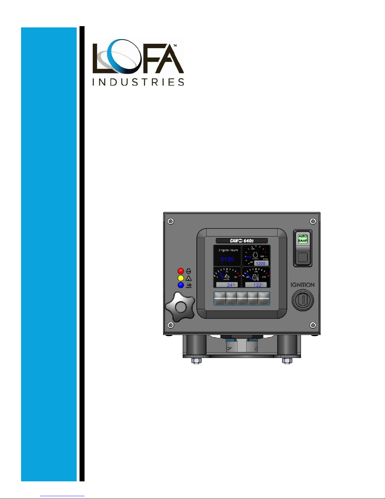
CANplus®640c Control Panel Operation Manual
October 2018
LOFA Document No. 463-3002-22
Page 2

Disclaimer: The contents of this document are not to be used for advertising, publication, or promotional purposes. Citation
of trade names does not constitute an official endorsement or approval of the use of such commercial products. All product
names and trademarks cited are the property of their respective owners.
DESTROY THIS DOCUMENT WHEN NO LONGER NEEDED. DO NOT RETURN IT TO THE ORIGINATOR.
Page 3

Table of Contents
1 Important Safety and Emissions Information ................................ .......................... 1
1.1 Safety Symbols ........................................... ........... ...................................... 1
1.2 Safety Instructions ............................... ........... ........... ................................... 1
1.3 Auxiliary Engine Stop Disclaimer.............. ........... ............................................. 2
1.4 General Emissions Disclaimer . ........... ........... ................................................. . 3
1.5 Exhaust Emissions Compliance Disclaimer ................................................. ....... 3
2 Overview ............................................... ........... ................................................. 4
3 Display .................... ........... ............................................................ ........... ........ 6
3.1 Adjusting Lighting and Contrast .......................................... ........... .................. 6
3.2 Button Bar ....... ........... ................................................. ........... ........... .......... 7
3.3 Analog Gauge Pages.................... ........... ........... ........................................... 7
3.4 Digital Gauge Pages............................... ........... ........... ................................. 8
3.5 Single Analog Gauge................... ........... ........... ............................................ 9
3.6 Active Alarms... ................................................. ........... ........... ..................... 9
3.7 Alarm List......................................... ........... ........... ..................................... 9
3.8 Service Timers ....................................... ........... ........... ............................... 10
3.9 Menus ...... ........... ........... ................................................. ........... ............... 10
3.9.1 Menu Tree......... ........... ........... ................................................. ........... 11
3.9.2 Access Levels .... ........... ................................................. ........... ........... 13
4 Manual Operation.................................................... ........... ................................ 15
4.1 Throttle Control .......................................... ........... ........... ........................... 15
4.2 Ramp Throttle ................. ........... ........... ................................................. ..... 16
4.3 Rotary Throttle Control... ............................................................ ........... ........ 16
4.4 Stopping the Engine ...... ............................................................ ........... ........ 16
4.5 Autoramp™ ................. ........... ............................................................ ........ 17
5 Configuration .... ............................................................ ........... ......................... 19
5.1 Display Menu .................. ........... ........... ................................................. ..... 19
5.2 LOFA CANplus®Software Suite and LOFA CANplus®Config kit ....................... ..... 19
5.3 LOFA CANplus®Software Suite and a USB drive ............................. ........... ....... 20
6 Miscellaneous .............................. ........... .......................................................... 21
6.1 Emissions System Functionality .. ............................................................ ........ 21
6.2 CP640c Panel Wiring.... ................................................. ........... ........... ......... 21
6.2.1 Typical J1939 Wiring Topology ......................... ........... ............................... 21
6.2.2 Engine Harness Connector ......... ........... ........... ........................................ 22
6.2.3 Sealed Connectors ...... ........... ................................................. ........... ... 22
6.2.4 Unsealed Connectors ................. ........... ................................................. 22
Page ii LOFA document No. 463-3002-22 Page ii
Page 4

6.2.5 Harness Routing ........ ........... ................................................. ........... .... 24
6.3 Engine Starter Excitation Connection ............................ ........... ........................ 24
6.3.1 Starter Relay...................................... ........... ....................................... 24
6.3.2 Battery Circuit Requirements ............ ........... .............................................. 24
6.3.3 Battery Positive Connection .................................. ........... ........... .............. 24
6.3.4 Voltage Drop ............................ ........... ................................................. 25
6.3.5 Suppression of Voltage Transients (Spikes) ......................... ........... ........... ..... 25
6.3.6 Welding on Equipment with Electronic Controls ... ............................................ 25
6.4 Control System Troubleshooting....... ................................................. ........... ... 26
6.4.1 Testing a Warning or Shutdown ..... ............................................................ . 27
6.4.2 Testing CAN .................... ........... ........... .............................................. 27
6.5 Diagnostic Trouble Codes (DTC)................ ........... ........... ............................... 27
6.5.1 Typical SPNs . ............................................................ .......................... 27
6.5.2 FMI......................................................... ........... ............................... 27
LOFA document No. 463-3002-22 Page iii
Page 5

This page has been intentionally left blank.
Page 6
1. Important Safety and Emissions Information
1 Important Safety and Emissions
Information
1.1 Safety Symbols
This manual uses the following conventions to present IMPORTANT SAFETY INFORMATION to you.
Please read and follow ALL SAFETY INSTRUCTIONS.
IMPORTANT AND URGENT SAFETY INFORMATION - A HAZARD THAT
WILL, IF NOT AVOIDED, CAUSE SERIOUS INJURY OR LOSS OF LIFE.
IMPORTANT SAFETY INFORMATION - A HAZARD THAT
SERIOUS INJURY OR LOSS OF LIFE.
ADDITIONAL IMPORTANT INFORMATION
1.2 Safety Instructions
Please read and follow all safety instructions.
This document must be completely read and understood prior to installing,
testing, or operating the equipment described within. Further, this document
must be retained for current and future users of this equipment. Failure to
strictly follow the warnings and dangers presented within this document
could result in damage to equipment, damage to property, bodily injury or
death.
MIGHT
CAUSE
LOFA products are not designed or approved for use as critical components
of any safety device or system that is intended to prevent bodily injury,
protect life, or prevent property damage.
LOFA document No. 463-3002-22 Page 1
Page 7
1. Important Safety and Emissions Information
The specifying Original Equipment Manufacturer (OEM) and/or installer of
any LOFA panel is responsible for all safety labeling and operator education
regarding the safe operation of this panel and the operation of the specific
machine that this panel is installed upon including conformance to exhaust
emissions regulations.
LOFA products are not designed for, or intended for use on, applications
requiring explosive proof components. Further, LOFA products are not
designed for, or intended for application within, hazardous or explosive
environments.
The installer of this LOFA product is solely responsible for ensuring that
all OSHA, ANSI, CE, or other applicable standards are met with respect
to LOFA panel applicability, machine guarding, general safety guidelines,
labeling, and warnings.
The installer of this LOFA panel and/or LOFA harness is responsible for the
correct sizing and integration of a suitable fuse/breaker on the un-switched
DC circuit supplying power to the LOFA panel.
Only trained and qualified persons may perform installation, testing, service,
or repair work on the LOFA product.
The seller hereby expressly disclaims all warranties, either expressed or
implied, including any implied warranty of merchantability or fitness for a
particular purpose, and neither assumes nor authorizes any other person
to assume for it any liability in connection with the sale of such products.
Please refer to www.LOFA.net for details on LOFA Industries, LLC warranty
policies.
LOFA Industries, LLC has provided this document as a reference. We
try to keep this document updated with the latest information regarding
your LOFA product. However, changes do occur and LOFA reserves the
right to make changes to the design of the LOFA products and supporting
documentation without notice.
Page 2 LOFA document No. 463-3002-22 Page 2
Page 8
1. Important Safety and Emissions Information
1.3 Auxiliary Engine Stop Disclaimer
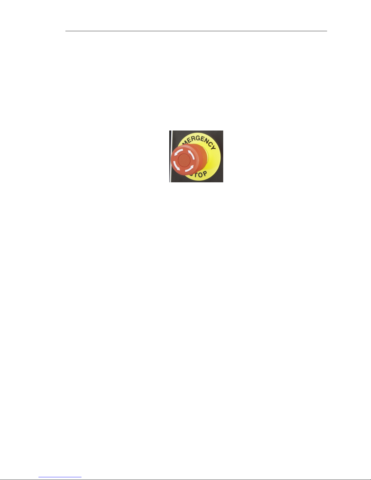
This panel or harness may include an optional Auxiliary Engine Stop feature.
the Auxiliary Engine Stop feature is NOT intended to function as the machine/equipment
Emergency Stop or be purposed as an Emergency Stop for safety purposes.
manufacturer must provide a separate Emergency Stop switch to meet safety mandates or emergency machine shutdown functionality. The sole design intent of the Auxiliary Engine Stop Feature
is to provide for engine shutdown in the event of a keyswitch malfunction. The panel key/lever switch
should always be used as the primary engine shutdown method.
Please note that
The machine
1.4 General Emissions Disclaimer
This panel may include provision(s) for operator input such as FORCE REGENERATION, INHIBIT
REGENERATION, INTERLOCK, and others specific to US and International emissions regulations.
Responsibility for emissions-related inputs and compliance with emissions regulations is solely that
of the owner and/or operator of the machine/engine on which this panel is connected.
1.5 Exhaust Emissions Compliance Disclaimer
This panel is equipped with operator-programmable parameters. The engine/machine as a function
of the emissions system can/could initiate, via the engine ECU (engine control unit), certain required
emissions operations such as regeneration of the DPF (diesel particulate filter), or other emissions
system maintenance, while the engine is running. The owner/operator of the engine/machine is
solely responsible for any adverse effects or damage to the engine, engine emissions system, or
other damage that could occur as a result of starting or stopping the engine/machine during any
ECU initiated emissions event.
LOFA document No. 463-3002-22 Page 3
Page 9
2. Overview
2 Overview
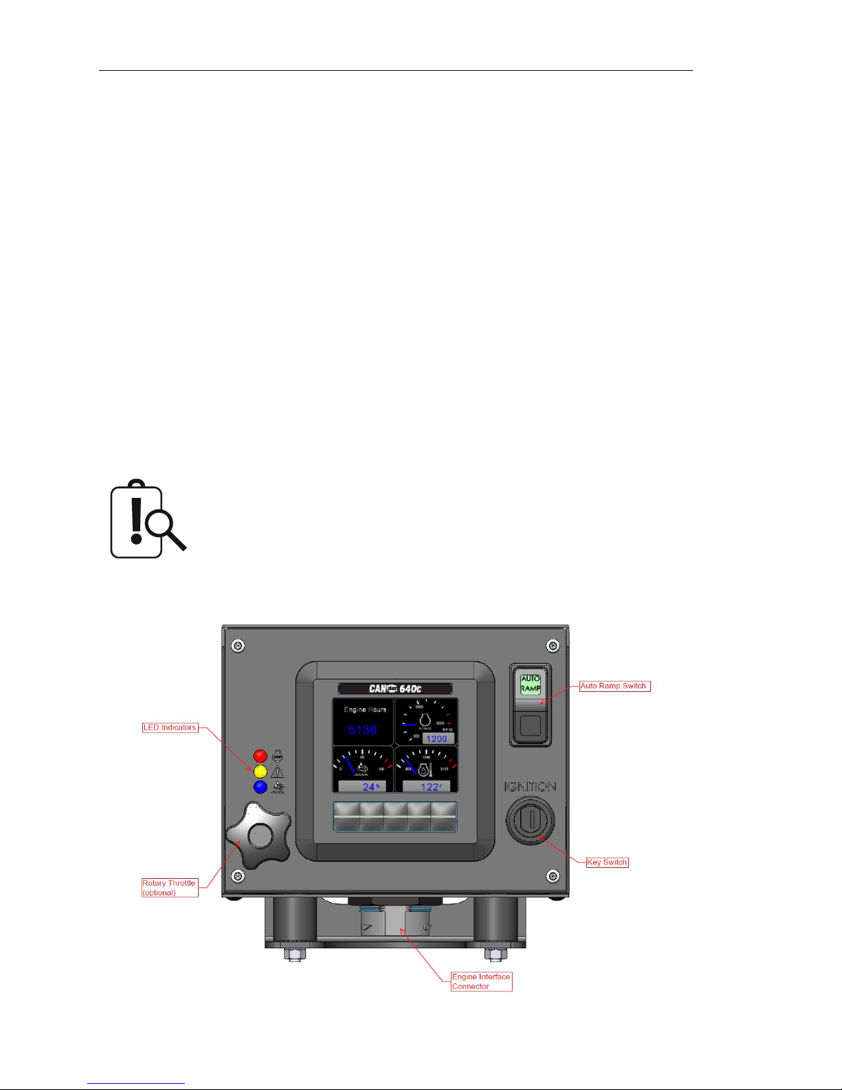
The LOFA CP640c control panel is an economical platform for EPA Tier 3, EPA Tier 4 (interim), and
EPA Tier 4 electronically governed diesel engines. Graphical gauge pages or a single large analog
gauge are displayed on the 3.5-inch diagonal LCD. Virtually any SAE J1939 parameter reported
by the ECU (Engine Control Unit) can be displayed including, but not limited to: RPM, coolant
temperature, oil pressure, engine hours, voltage, exhaust emissions system state, and diagnostic
codes. The backlit display is clearly readable in both bright sunlight as well as total darkness and
housed in a rugged IP66 rated housing. The CP640c can optionally include three (3) bright LEDs to
indicate Faults, Warnings, and Emission-Related Alerts.
All components are installed in a heavy-duty, vibration isolated, metal enclosure designed to withstand the most extreme industrial applications. External weather resistant switches and controls
facilitate convenient operator inputs/controls. Active fault conditions are displayed in plain language
on popup messages and can be viewed in the fault list. Various diagnostic screens allow detailed
investigation of the CAN bus data stream.
All diagnostic and emissions related messages displayed on the CP640c
are generated by the engine ECU or other attached devices. The operator
must be familiar with the engine manufacturer ECU messages and icons in
order to react accordingly with respect to emissions compliance, service,
and diagnostic message response.
Page 4 LOFA document No. 463-3002-22 Page 4
Page 10
2. Overview
LOFA document No. 463-3002-22 Page 5
Page 11
3. Display
3 Display
The CANplus®display is a robust, sunlight viewable 3.5” QVGA color display with five (5) integrated
backlit buttons housed in a rugged, water-tight IP66 rated enclosure. The five soft keys simplify and
enhance the user interface by providing a configurable auditory beep and positive tactile feedback
when pressed.
The display can show virtually any SAE J1939 parameter reported by the ECU, including RPM,
engine temperature, oil pressure, and diagnostic codes. It can be easily configured to customer
preference, including gauge type (analog or digital), gauge arrangements, gauge size, units, and
language.
Different software versions may have slightly different displays.
3.1 Adjusting Lighting and Contrast
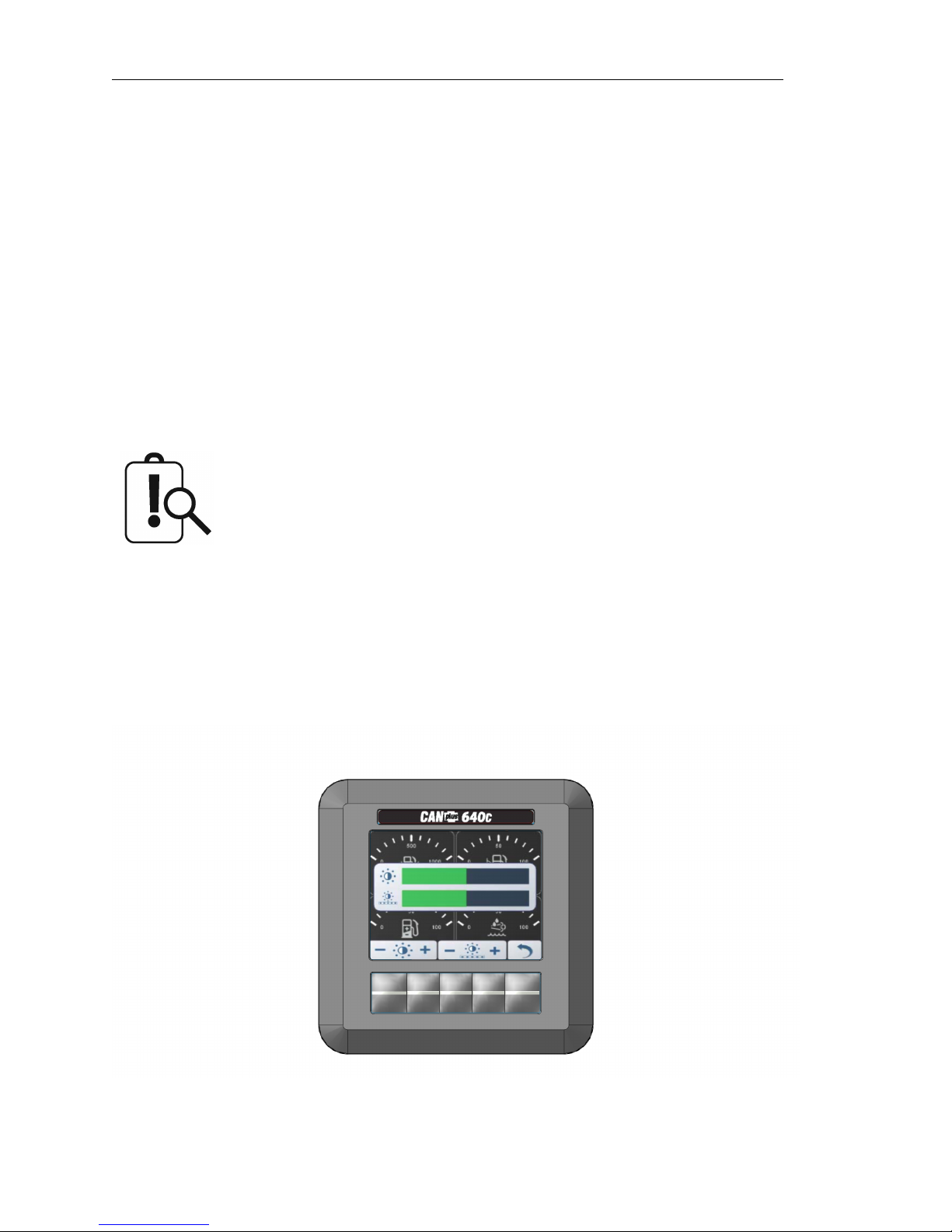
Pressing button 5 (the right-hand button) when there is no menu bar opens the lighting and contrast
menu bar. The display has a number of back-lighting levels allowing the display to be read in the
dark. The level is adjusted by pressing buttons 1 (decrease) or button 2 to (increase) illumination.
Contrast is adjusted in the same manner using buttons 3 and 4.
Page 6 LOFA document No. 463-3002-22 Page 6
Page 12
3. Display
The display adjusts the contrast with ambient temperature. Manual contrast
adjustments are only necessary with extreme climate change.
The menu is exited by pressing button 5. The lighting and contrast settings are retained after the
unit is powered off.
3.2 Button Bar
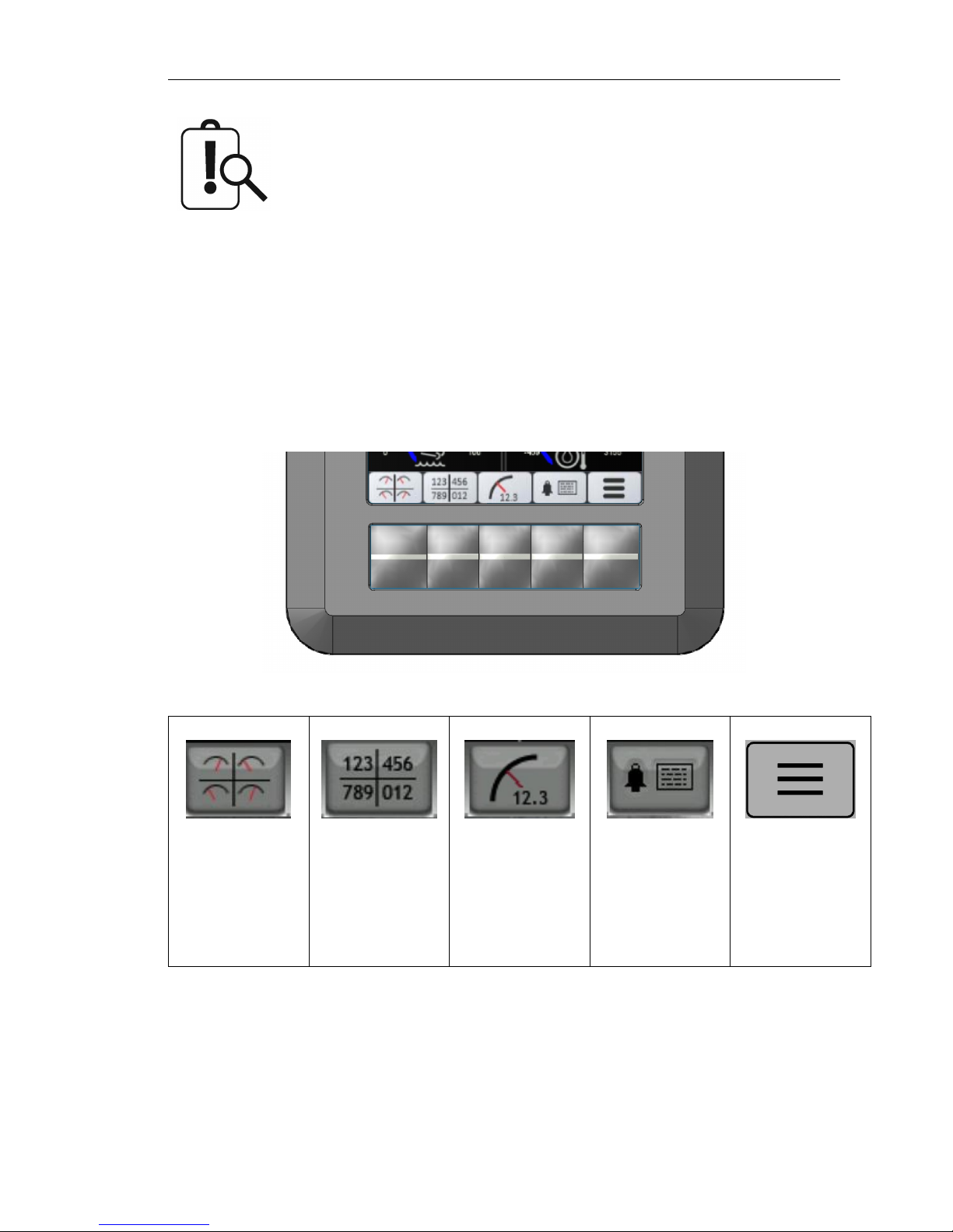
Pressing any of the first four (4) soft keys on the display will prompt the button bar key function
legend to appear at the bottom of the display above the keys. The button bar will show an icon above
the button which corresponds to its current function.
Button 1 Button 2 Button 3 Button 4 Button 5
Analog Gauge
Pages
Repeated
presses cycle
through the four
pages of analog
gauges
Digital Gauge
Pages
Repeated
presses cycle
through the four
pages of digital
gauges
Single Analog
Gauge
Repeated
presses cycle
through the
available digital
gauges
Active Alarm
Page
Displays active
alarms including
plain language
description
Menus
Opens Menus
3.3 Analog Gauge Pages
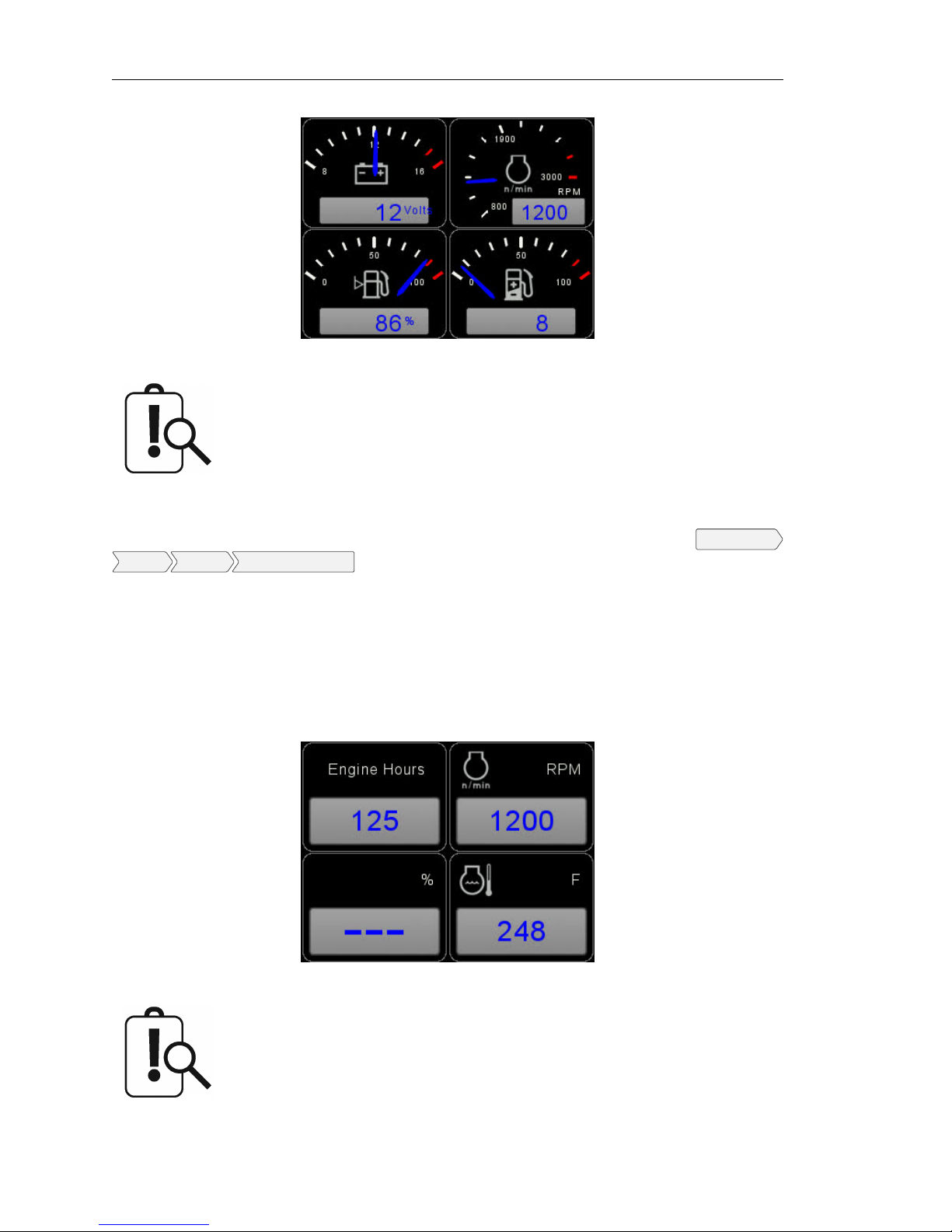
Analog Gauge Pages provide four (4) independently configurable pages of analog gauges. To enable
Analog Gauge Pages, press any of the first four (4) buttons to show the top level button bar and then
press button 1 to cycle through the pages.
LOFA document No. 463-3002-22 Page 7
Page 13
3. Display
Some items like Engine Hours are displayed as a digital value even on
Analog Gauge Pages.
All sixteen (16) gauges may be configured to create an application-specific view of data. With Tech or
Admin level access, the four (4) analog gauge pages can be configured using the menu
Display Gauges Quad Gauge Pages
.
Configuration
3.4 Digital Gauge Pages
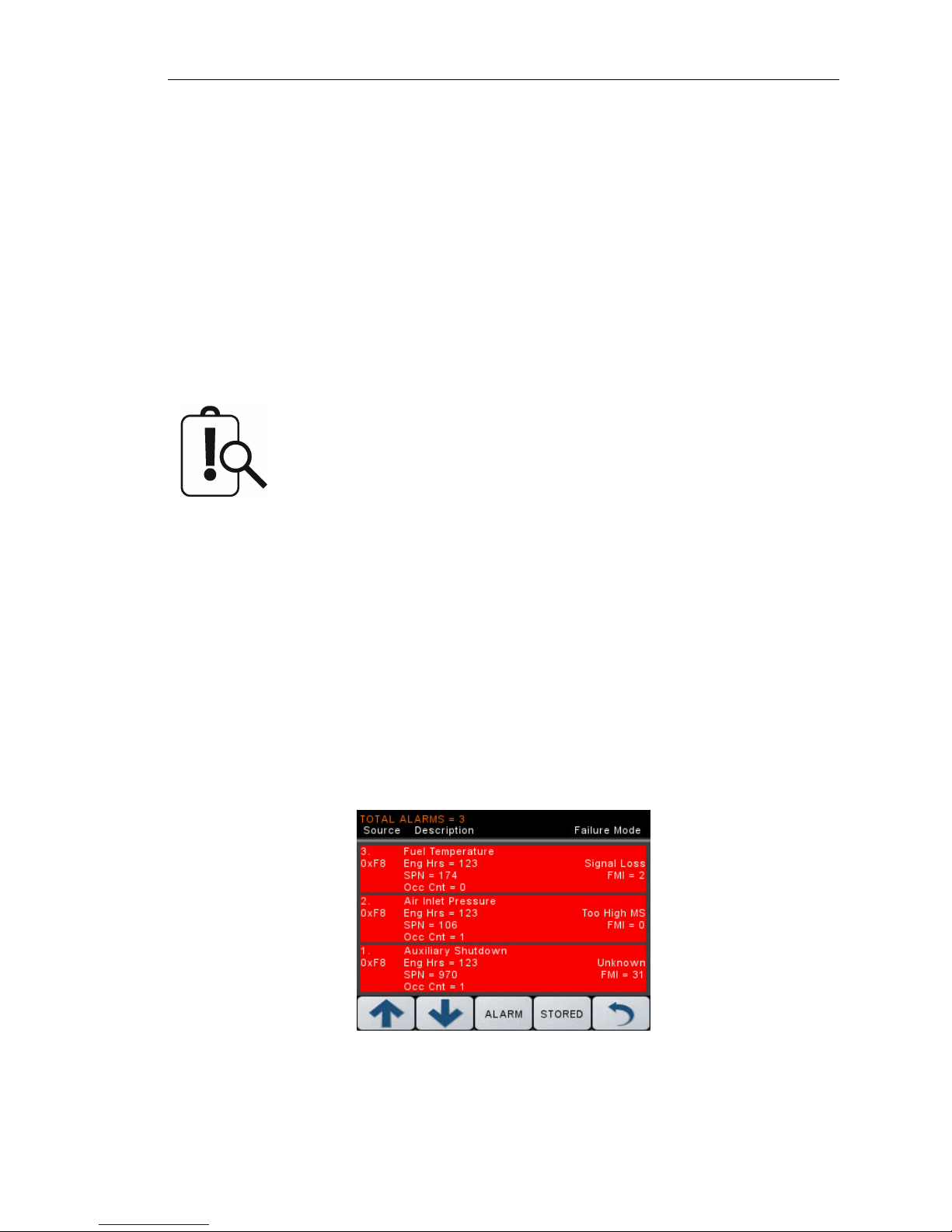
Digital Gauge Pages display the same data as the Analog Gauge Pages but in digital only format. To
enable Digital Gauge Pages, press any of the first 4 buttons to show the top level button bar and
then press button 2 to cycle through the pages.
The sixteen (16) gauges are the same for Analog and Digital Gauge Pages.
Adjustments in either Analog Gauge Pages or Digital Gauge Pages affect
the same gauge in the other mode.
Page 8 LOFA document No. 463-3002-22 Page 8
Page 14
3. Display
3.5 Single Analog Gauge
Single Analog Gauge uses the entire display for a single large analog gauge. This mode is enabled
by pressing any of the first 4 buttons to show the top-level button bar and then press button 3 to
cycle through the available gauges. The active displayed gauge is stored when power is removed
(see Preferred Screen Store).
3.6 Active Alarms
When an active alarm is received, a flashing popup window is overlaid on the current screen when
an active alarm is received. The popup includes a plain language description in addition to the
standard SPN/FMI (Suspect Parameter Number/Failure Mode Indicator) pair defined by the SAE
J1939 standard. Additionally, if enabled, the beeper sounds as an audible cue.
Standard J1939 abbreviations are used for alarms. MS = Most Severe,
MOD = Moderately Severe, LS = Least Severe.
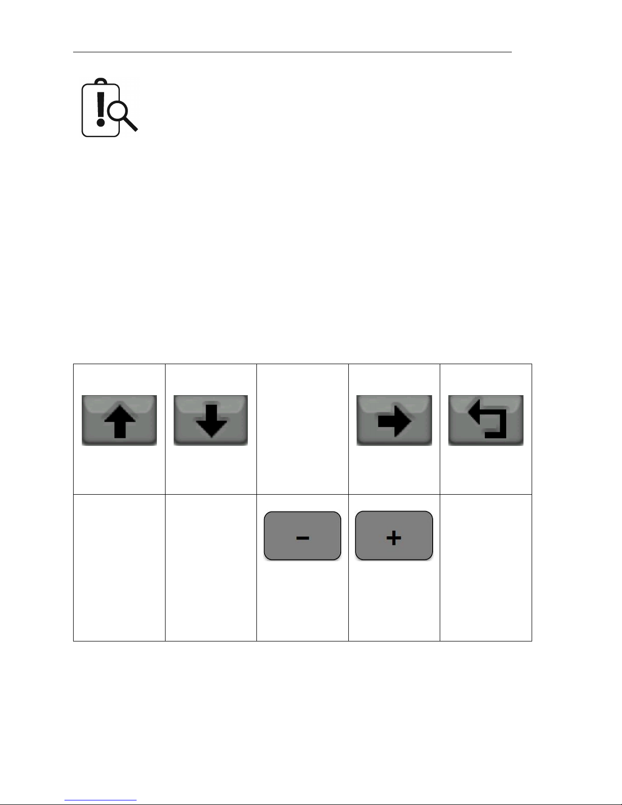
3.7 Alarm List
The Alarm List is accessed by pressing any button while an alarm popup is displayed or by pressing
any of the first 4 buttons to show the button bar and then button 4. Alarms not yet acknowledged are
shown in white on red while acknowledged alarms are shown in white on black. The list also indicates
when the alarm occurred if engine hours are available. The most recent alarm is displayed at the
top of the list. The list can be scrolled using buttons 1 and 2 and alarms acknowledged by pressing
button 3. The Alarm List can be closed by pressing button 5 once the alarms are acknowledged.
An alarm indicator is displayed near the upper right corner of the display as long as alarms are
active. The indicator and alarm messages in the list are automatically removed when the alarm has
not been received for a few seconds.
LOFA document No. 463-3002-22 Page 9
Page 15
3. Display
Only active faults are displayed in the alarm list. Once a fault is corrected it
is automatically removed from the list. To view previously active faults press
the ”STORED” button.
3.8 Service Timers
The CP640c display provides sixteen (16) service timers to alert the operator of required maintenance.
The time interval for each timer can be adjusted in increments of ten (10) hours. A popup message
is displayed after the display self-test if a timer (or timers) has expired alerting the user that service
is required. The message is displayed on each power up until the elapsed timer is disabled or reset.
The service timers can have their respective names customized to monitor engine- and pump-related
parameters. All sixteen (16) service timers can be monitored via wireless telemetry.
3.9 Menus
The menu pages can be accessed by pressing and holding button 5. After one (1) second, the
top-level menu page will appear. From there the functions of the five display buttons change to allow
navigation and selecting and modifying parameters.
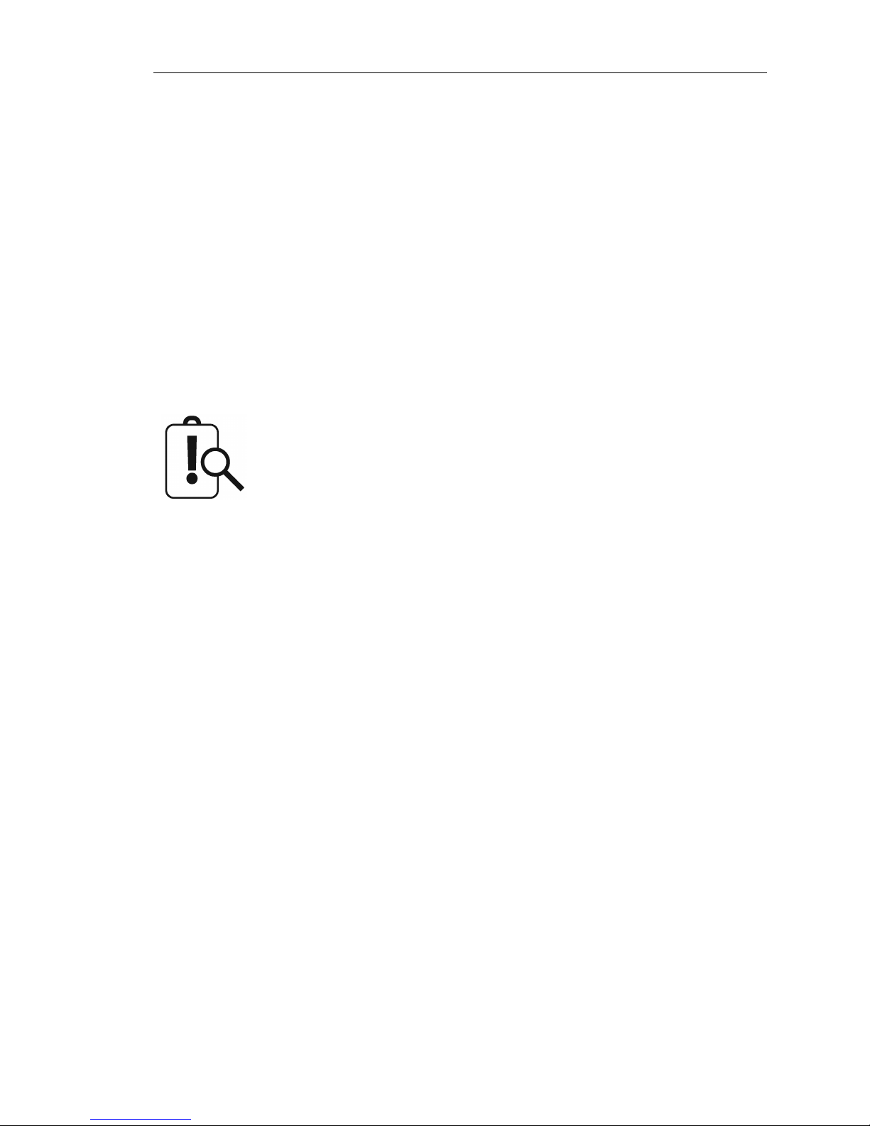
Button 1 Button 2 Button 3 Button 4 Button 5
Sroll Up Scroll Down [Intentionally
Blank]
Decrement Value Increment Value
or or
Previous
Selection
The menus pages can also be accessed by pressing and holding the optional Rotary Control using
LOFA’s RotaryPlus™ technology:
Go into Selected
Submenu
Next Selection
Return to
Previous Menu
• Push and hold the rotary for one (1) second to open menus main page
• Move down through the menu choices with clockwise rotations
Page 10 LOFA document No. 463-3002-22 Page 10
Page 16

3. Display
• Move up through the menu choices with counter clockwise rotations
• Select menus, options, and entries by pushing in the rotary knob (click)
• Increase numerical entries with clockwise rotations
• Decrease numerical entries with counter clockwise rotations
• Pushing in the rotary knob twice quickly (double click) backs up to the previous menu
•
At any time, pushing and holding the rotary for one (1) second causes the display to completely
back out of the menu mode showing the main gauges
3.9.1 Menu Tree
The menu tree is shown below. Some menus items are suppressed based on the access level
currently allowed. The color of the text in the tree indicates the minimum access level required for
this particular item to be available for displaying.
Black = User
Green = Tech
Red = Admin
Display
• Language
• Units
– Distance
– Pressure
– Volume
– Temperature
• Button Beep ON/OFF
• Gauges
– Quad Gauge Pages (configure which gauges will be displayed)
1-4
*
– Voltmeter - 12V/24V
LOFA document No. 463-3002-22 Page 11
Page 17

3. Display
System
• Restore Defaults (recall factory defaults)
• Import Config (import a new configuration file from the USB port)
• Export Config (export current configuration to a file on the USB port)
• PINs (see section 3.9.2)
– Elevate Access Level
– Entry - On/Off
– Change
• CAN bus
– TSC1 Address (panel sends the TSC1 messages from this CAN address)
– Panel Address (CAN address for the panel)
– CM1 Address (panel sends the CM1 messages from this CAN address)
– Config Address (panel address for Config program)
• Engine Type
• Engine Specific Settings
• Date and Time
• About
Throttle
• Min / Idle / Max RPM
• Switch/Rotary
– Increments
– Max Change Per Second
• Autoramp (see section 4.5)
– RPM Settings
Intermediate
*
Run
*
– Time Profile
Warm Up
*
Ramp to Intermediate
*
Ramp to Run
*
Ramp to Cooldown
*
Cooldown
*
Page 12 LOFA document No. 463-3002-22 Page 12
Page 18

3. Display
Telemetry
• Status
• Address (CAN address for the telemetry device)
Service Timers
• Timers 1-16 (each timer is listed separately)
– Hours remaining
– Reset
Tier 4 Control
• Inhibit - OFF/ON (inhibit Regenerations)
• Request Force (request a Force Regeneration; depending on conditions, ECU may not honor)
• Status (database Viewer for Tier 4 related status messages from the ECU)
Database Viewer
3.9.2 Access Levels
The available menu items are dependent upon the current access level. The current access level is
shown in the upper right corner while in the menus. The CP640c supports up to three (3) independent
PINs that are configurable. The standard LOFA configuration has the following PINs settings:
• User = 1000
• Tech = 1111
• Admin = 2222
• Menu PIN Required = OFF
Elevate Access Level
When the panel is turned on, the access level reverts to the User level. To gain access to
Tech or Admin levels, use the Elevate Access Level menu
Elevate Access Level
.
Configuration System PIN Settings
The panel will prompt for a PIN input. User, Tech, or Admin level access will be granted based on
which PIN is entered. Example: If the Tech level PIN is entered, Tech level access will be granted
and similarly if Admin or User level PINs are entered. If the entered PIN does not match User, Tech,
or Admin, then ”Incorrect PIN” is displayed and the access level reverts to User.
LOFA document No. 463-3002-22 Page 13
Page 19

3. Display
Once elevated, the access level stays in effect until the panel is turned off.
PIN Change
PINs can be changed via the Menu by selecting
The PIN being changed is the PIN for the current access level. Example: At User level, only the User
PIN can be changed. To change the Tech PIN, use the Elevate Access Level menu and enter the
correct Tech PIN. Then go to the PIN Change menu to change the Tech PIN.
Menu PIN Required OFF
• Accessing the menu is allowed with no PIN input required
• Only User access level items are displayed
• Use the Elevate Access Level menu to access Tech of Admin menu items
Menu PIN Required ON
• PIN is required to access the menu
•
User, Tech, or Admin level access will be granted based on which PIN was entered. If PIN does
not match the User, Tech or Admin PIN, then the panel will display invalid PIN.
Once an access level is granted, that level is retained until the key is turned off. When the key is turn
back to the ON position, the access level reverts back to User and follows the Menu PIN Required
setting.
Configuration System PIN Settings PIN Change
.
Page 14 LOFA document No. 463-3002-22 Page 14
Page 20
4. Manual Operation
4 Manual Operation
1. Ensure that the Auxiliary Engine Stop (if fitted) is not activated.
2. Turn the keyswitch to the run position.
3. Turn the keyswitch clockwise to the start position and hold until the engine successfully starts.
4. Release keyswitch.
If the engine fails to start, the keyswitch must be returned to the off position prior to subsequent start
attempts.
The ECU will not preheat unless conditions warrant. If necessary, starting
the engine may be attempted by turning the key to the start position without
waiting for preheat to expire.
4.1 Throttle Control
Throttle operation is determined by the type of throttle operator(s) installed along with the configured
values of:
• Minimum Requested RPM
• Idle RPM
• Intermediate RPM
• Run RPM
• Maximum Requested RPM
The ECU determines how the engine responds to the throttle requests and will not allow the engine
speed to fall below the ECU minimum RPM or go above the ECU maximum RPM. The ECU minimum
and maximum RPM values are determined by the ECU ”payload” and typically require the engine
manufacturer’s configuration tool to adjust. The ECU will honor RPM requests that are above the
ECU’s minimum RPM as well as RPM requests that are below the ECU’s maximum RPM.
Therefore, to avoid confusion it is best to NOT set the panel’s Minimum Requested RPM below the
ECU’s minimum RPM or above the ECU’s maximum RPM.
Example: The panel’s Minimum Requested RPM is set to 800 RPM yet the ECU payload defines the
engine minimum speed to be 900 RPM. In this case, the engine will not run at 800 RPM despite the
CP640c control panel requesting a lower engine speed. The ECU will ignore all RPM requests that
are below 900 RPM, resulting in a minimum speed of 900 RPM.
LOFA document No. 463-3002-22 Page 15
Page 21
4. Manual Operation
The panel’s Minimum Requested RPM and Maximum Requested RPM can
be configured using the CANplus®Suite Software, or via menus within the
display (if enabled by PIN). See Configuration section for more information.
4.2 Ramp Throttle
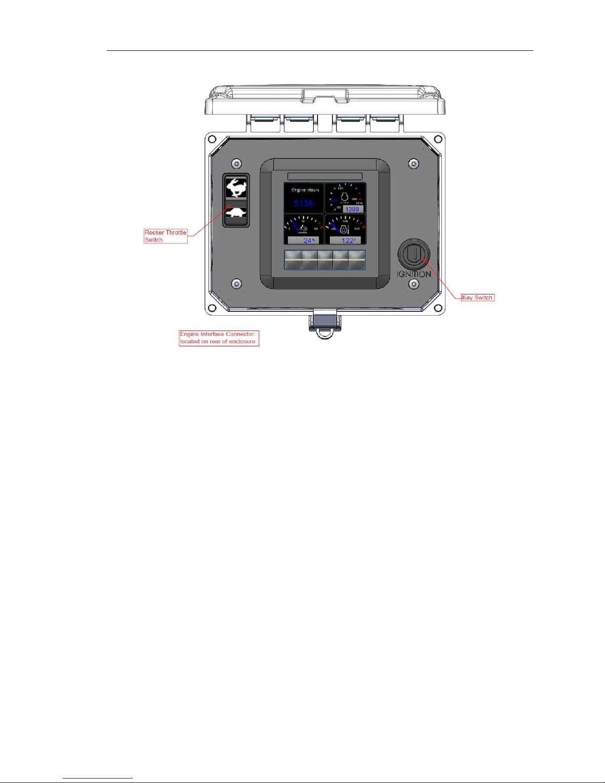
The standard Ramp Throttle uses a momentary rocker switch to adjust the requested engine speed.
All throttle requests are sent directly to the engine using CAN throttle control.
Throttle control requires CAN throttling to be enabled in the ECU. CAN
throttling is also known as Torque Speed Control or TSC1.
When first started the requested engine speed is Idle RPM.
•
Pressing and releasing the rabbit icon increases the speed by the switch/rotary increment
value (default = 50 RPM).
•
Pressing and holding the rabbit icon causes the speed to continue to increase (ramp) until
the maximum speed is achieved.
• Pressing and releasing the turtle icon decreases the speed by the switch increment value
(default = 25 RPM).
•
Pressing and holding the turtle icon causes the speed to decrease (ramp) until the minimum
speed is achieved.
•
The CP640c will smoothly ramp the RPM up and down using the Max RPM change / s value
(500 default). This value can be changed in the
Throttle Switch/Rotary Max Change / s
menu.
4.3 Rotary Throttle Control
The optional Digital Rotary Throttle uses a rotary switch to simulate the operation of a throttle. When
the engine is first started, the requested engine speed is always Idle RPM. Turning the throttle knob
clockwise increases the requested engine speed by the switch/rotary increment value (default = 50
RPM). Turning the throttle knob counter-clockwise decreases the requested engine speed.
4.4 Stopping the Engine
To stop the engine simply turn the key to the ”OFF”’ position. Do not use the Auxiliary Engine Stop
(if fitted) to stop the engine under normal conditions.
Page 16 LOFA document No. 463-3002-22 Page 16
Page 22
4. Manual Operation
4.5 Autoramp™
The optional Autoramp™feature allows the use of configurable warm up and cooldown profiles to
help protect engines and other assets such as plumbing, or to insure proper ramp up and down of
pressure or flow.
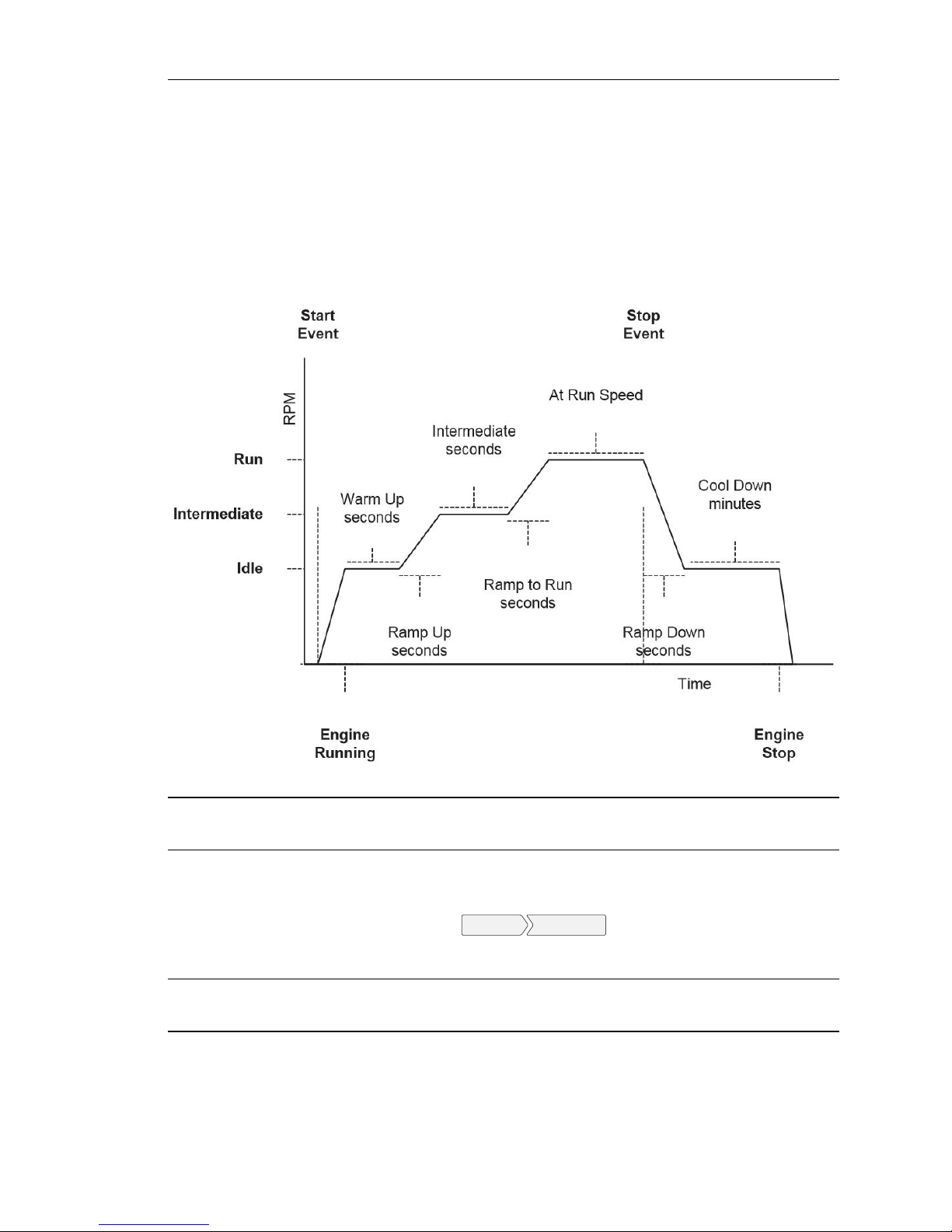
The Autoramp™feature uses the configurable Autoramp™RPM and time profiles. The following
diagram shows the settings and the relationship to each other.
Idle RPM
Intermediate RPM
Run RPM
Selects the RPM the control system will request for idle speed. If the engine
is started, it will always begin running at Idle speed.
Selects the RPM the control system will request for intermediate speed.
Intermediate speed is a specific speed point that the engine will pause at
during the ramping up cycle. The Intermediate speed pause duration is
configurable in the
can be used to prime pump or charge lines during the optional automatic
ramp operation.
Selects the RPM the control system will request for run speed. The run
speed is the normal operating speed.
Autoramp Time Profile
menu. The intermediate speed
LOFA document No. 463-3002-22 Page 17
Page 23
4. Manual Operation
The minimum engine speed is controlled by the ECU. Requesting a lower
speed causes the engine to run at the ECU minimum speed. RPM limits
are configured into the panel to limit the requested speed. Changing the
panel’s Minimum Requested RPM and Maximum Requested RPM requires
a Tech Level Password or higher to access those settings. Those values
can also be adjusted using the CANplus®Configuration Suite.
If an Intermediate RPM is not desired, it can be set to the same speed as
Idle RPM and also setting Ramp Up s (seconds) to zero (0) seconds (see
Ramp Profile).
Intermediate and Run RPM settings are only applicable during the optional
automatic ramp operation and have no affect when the panel is manually
started.
To utilize the optional Autoramp™feature, the Autoramp™RPM and Time setting must be configured.
Once configured, turn the key to the ON position from the OFF position without cranking the engine.
With the engine off, press and release the Autoramp™switch at the top right of the control panel.
After releasing the switch, the Autoramp™LED will start blinking, and the panel will automatically
start the engine. The panel will follow the configured Autoramp™RPM and time profiles until the
Run Speed is achieved, at which point, the LED will turn solid green.
Once the LED stays solid green, the engine’s RPM can be adjusted as desired. Once the job is
complete, pressing the Autoramp™switch will cause the Autoramp™LED to blink again and the
panel to automatically ramp the engine down following the configured RPM and time profiles. When
the Cooldown period is over, the panel will automatically shut down the engine and the LED will turn
off.
Page 18 LOFA document No. 463-3002-22 Page 18
Page 24

5. Configuration
5 Configuration
The CP640c has been preloaded with factory default or optionally a custom OEM-specific configuration to ensure easy start-up and commissioning. To support the diversity of applications, the control
panel is easily configured on demand. Accessing configurable settings can be accomplished in three
ways:
1. Display Menu
2. LOFA CANplus®Software Suite and LOFA CANplus®Config kit
3. LOFA CANplus®Software Suite and a USB drive
5.1 Display Menu
Most commonly, accessible parameters can be changed on-site or in a facility by navigating the
display using the soft keys to find the appropriate menu page and data field. The available menu
items are dependent upon the current access level (see section 3.9.1 for available menu items).
Easy to follow menu navigation diagrams are located throughout the user manual and accompany
each section which describes a configurable operation or setting.
5.2 LOFA CANplus®Software Suite and LOFA CANplus®Config kit
In situations where multiple units must be reconfigured, or in the case of a single unit which
requires complete reconfiguration, it is recommend to use the CANplus®Software Suite, which
is LOFA’s proprietary configuration software. The software suite is meticulously maintained and
regularly updated. These free updates include software enhancements and new functionality,
and they ensure compatibility with evolving technologies. The latest update can be found at
http://www.lofa.net/updates/.
The LOFA CANplus®Config kit (LOFA part number 010-6750-01) includes:
1. An adapter harness that connects to the panels engine interface connector
2. An AC power supply
3. A USB to CAN bus hardware adapter
With this kit, a panel’s configuration can be read from the panel or written to the panel via CAN bus.
During read or write operations, the panel must be the only CAN bus device (using the included
adapter harness insures proper operation during configuration read or writes). A demonstration
video that shows how to use the CANplus®Config kit and the software suite can be viewed at
http://www.lofa.net/product-support/videos/.
LOFA document No. 463-3002-22 Page 19
Page 25
5. Configuration
5.3 LOFA CANplus®Software Suite and a USB drive
The CP640c introduces the ability to import and export configurations using a USB drive avoiding
the need to purchase and have onsite a LOFA CANplus®Config kit as well as disconnecting the
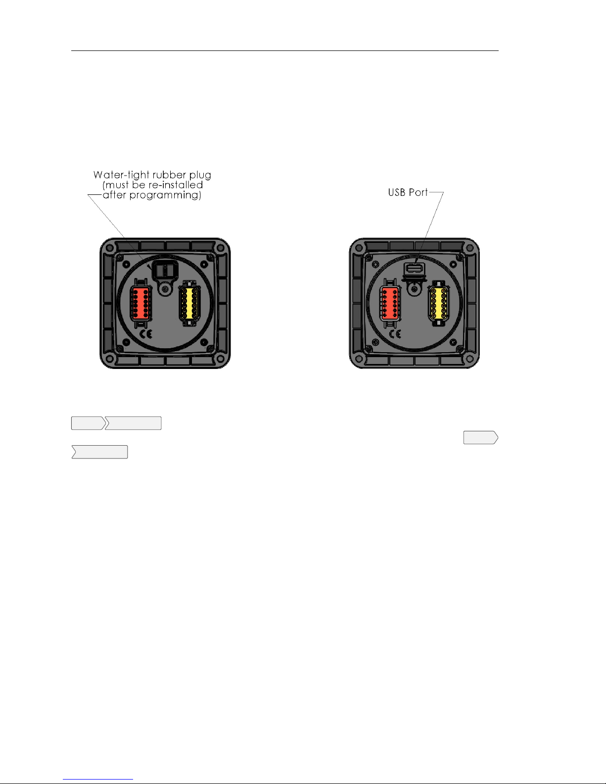
panel from the engine. The panels USB port can be accessed by simply removing the four (4) front
faceplate screws. The USB port location is shown below protect by a water-tight rubber plug.
Install the USB drive in the panel’s USB port. The current configuration can be exported by going to
System Export Config
Admin level (see section 3.9.2 Access Levels). A new configuration is imported by going to
Import Config
be running when importing a new configuration.
When finished with exporting of importing configurations, remove the USB drive, reinstall the
protective water-tight rubber plug, and secure the faceplate with the four (4) screws.
. New configuration changes take effect immediately. Therefore, the engine should not
. To import a new configuration, the menu access level must be at the Tech or
System
Page 20 LOFA document No. 463-3002-22 Page 20
Page 26
6 Miscellaneous
6.1 Emissions System Functionality
GENERAL EMISSIONS DISCLAIMER This panel may include provision(s)
for operator input such as FORCE REGENERATION, INHIBIT REGENERATION, INTERLOCK, and others specific to US and International emissions
regulations. Responsibility for emissions related inputs and compliance
with emissions regulations is solely that of the owner and/or operator of the
machine/engine on which this panel is connected.
CAUTION Carefully read and understand the engine manufacturer
owner/operator manual. Your engine manufacturer provides specific information regarding the exhaust emission system of your engine. This
information is maintenance, procedural, and safety related. Failure to
exactly follow the engine manufacturer instructions and schedules could
potentially result in harm or injury to you and/or others. Further, failure to
exactly follow the engine manufacturer instructions and schedules could
result in damage to your engine and/or equipment.
6. Miscellaneous
The LOFA CANplus®display reports emissions messages received from the engine ECU. Depending
on the received message, icons or symbols may be displayed on the screen. Some messages/icons
are displayed as an overlay (inhibit symbol shown at left). Other symbols/icons may cover most of the
screen. The operator MUST respond to the indications on the display following engine manufacturer
recommended procedures/actions. Please note that indications shown by the display may vary with
respect to engine manufacturer and may vary between engine models from the same manufacturer.
6.2 CP640c Panel Wiring
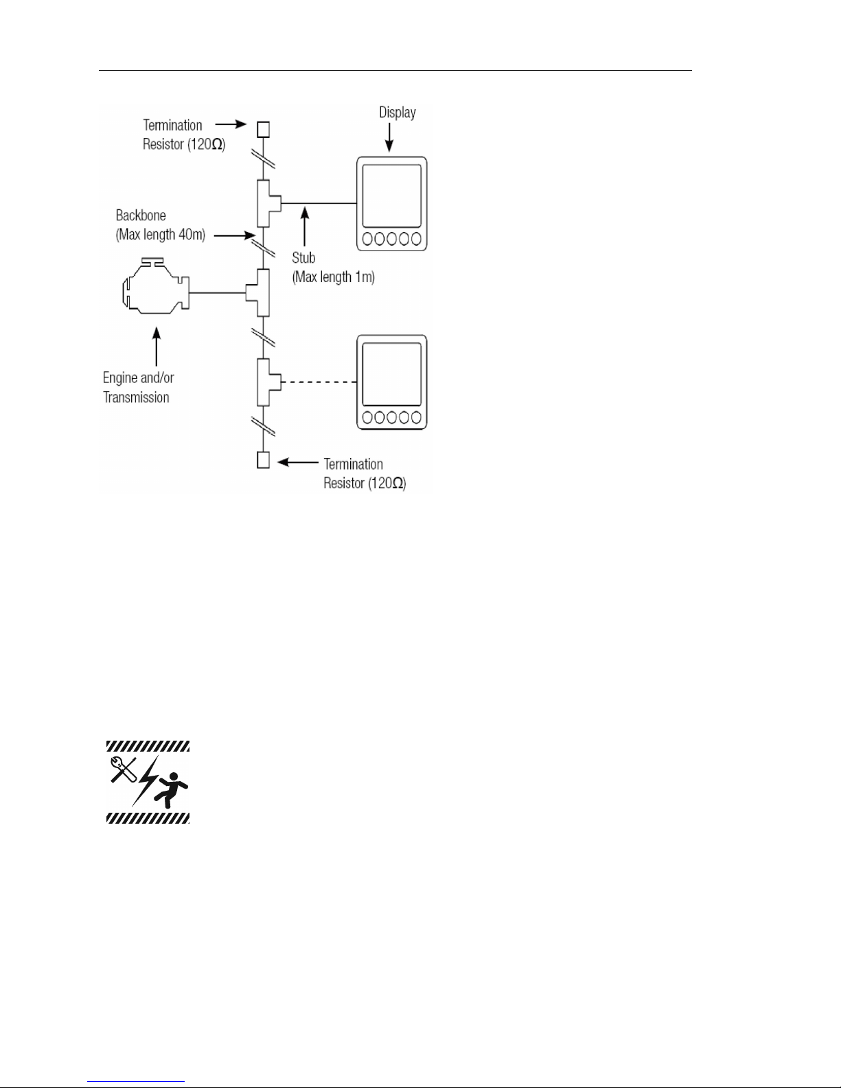
Most electronically governed engine installations include a harness with built in J1939 backbone.
Use twisted shielded pair with a drain wire for CAN wiring terminated with 120Ω resistors at each
end. The maximum length for the CAN bus is 131 feet (40 m) and stubs should not exceed 39 inches
(1m) in length.
6.2.1 Typical J1939 Wiring Topology
LOFA document No. 463-3002-22 Page 21
Page 27
6. Miscellaneous
6.2.2 Engine Harness Connector
Connection to the engine is provided by a Deutsch/TE 21 pin connector (part number HDP24-2421PE). The mating connector is Deutsch/TE part number HDP26-24-21SE.)
Signals are shown in table 1 on the facing page.
6.2.3 Sealed Connectors
The provided Deutsch sealed weather-proof plug includes a locking ring device which must be turned
counter clockwise to separate the connectors. To positively seat the connectors the locking ring is
turned clockwise.
LOFA does not recommend using dielectric grease or sealant with sealed
connectors. These chemicals may cause seal damage and allow water
entry. Use LOFA provided cavity plugs to seal the connector if wires are
removed.
6.2.4 Unsealed Connectors
For unsealed connectors exposed to the elements, LOFA recommends using dielectric grease to
protect contacts.
Page 22 LOFA document No. 463-3002-22 Page 22
Page 28

6. Miscellaneous
Pin Signal Description Direction Notes
A Preheat In/Out In/Out 10A Maximum Output
B Battery Supply In Connect direct to battery ‘+’ via 30A Fuse
C Ground N/A Connect direct to battery ‘-’
D Starter Out 10A Maximum
E Ground N/A Connect direct to battery ‘-’
F CAN Shield N/A
G ECU/Solenoid Out 10A Maximum
H Temperature Sender In Resistive
J Alternator Excitation Out 5A Maximum
K Tach In Alternator or single ended mag-pickup
L No Connect N/A
M Auxiliary Switch 2 In Ground Input
N Temperature Switch In Ground Input
P Oil Pressure Sender In Resistive
R Throttle Switch In Connected to ‘S’ via 390Ω resistor
S Throttle Switch Return Out
T Oil Pressure Switch In Ground Input
U CAN Low In/Out J1939
V CAN High In/Out J1939
W Auxiliary Switch 1 In Ground Input
X Fuel Sender In Resistive
Table 1. Engine Harness Connection
LOFA document No. 463-3002-22 Page 23
Page 29
6. Miscellaneous
LOFA does not recommend using sealant with unsealed connectors.
Sealant traps moisture in the connector and encourages corrosion.
6.2.5 Harness Routing
The minimum routing radius of the wiring harnesses should be at least two times the diameter of the
wiring harness. Bends should be avoided within 1 inch (25 mm) of any connector in order to avoid
seal distortion allowing moisture to enter the connector.
6.3 Engine Starter Excitation Connection
6.3.1 Starter Relay
General Starter Relay Specifications
Minimum Starter Relay (Continuous) Rating 60A@12V 30A@24V
Maximum Starter Relay Excitation Current Draw 5A@12V 3A@24V
LOFA provides suitable heavy duty relays and generic starter relay wiring kits in both 12v and 24V;
please contact your LOFA reseller for more information.
6.3.2 Battery Circuit Requirements
Improper wiring can cause electrical noise, unreliable operation and may
damage the control system or other components. All power connections
must be free from foreign materials, including paint, which may interfere with
proper connection. A reliable 30A maximum fused power circuit must be
provided for the control system. LOFA recommends the power connection
be made directly to the battery with the fuse electrically close to the battery.
Grounding through frame members is not recommended. All circuit paths
must be capable of carrying any likely fault currents without damage. Do
not reverse the battery polarity. Attempting to crank the engine when the
polarity of the battery connections is reversed may damage the control
system.
6.3.3 Battery Positive Connection
The electronic control system operates on either a 12 VDC or 24 VDC electrical systems. The
unswitched battery positive connection to the control system is made at the weather proof connector.
The control system provides switched positive battery protected by solid-state MOSFETs. These
outputs include integral protection against overloads and short circuits.
Powering the control system through a 30A fused dedicated circuit reduces the possibility of system
damage.
Page 24 LOFA document No. 463-3002-22 Page 24
Page 30
6. Miscellaneous
Disconnecting the battery while the engine is running may result in damage
to electrical components. When using a battery disconnect switch, LOFA
recommends using a 2 pole switch to disconnect both the battery and
alternator output.
A maximum of three ring terminals should be connected to a power stud
in order to ensure integrity of the connection. The use of more than three
terminals can cause the connection to become loose.
6.3.4 Voltage Drop
If control system voltage drops below 6 volts for more than one tenth of a second, the control system
may reset causing the self-test to reactivate. Resetting the control system is equivalent to quickly
turning the keyswitch to off and back to run without starting the engine. Voltage drops can be caused
by a discharged battery, transients from external equipment, improper wire sizes, faulty wiring or
nearby lightning strikes.
6.3.5 Suppression of Voltage Transients (Spikes)
The installation of voltage transient suppression at the transient source is
required. LOFA follows SAE recommended electrical environment practices.
Inductive devices such as relays, solenoids and motors generate voltage transients and noise in
electrical circuits. Unsuppressed voltage transients can exceed SAE specifications and damage
electronic controls.
Relays and solenoids with built-in voltage transient suppression diodes are recommended whenever
possible. Refer to the illustration for proper installation of diodes when built-in voltage transient
suppression is not available.
Locate inductive devices as far as possible from the components of the electronic control system.
When using electric motors it may also be necessary to add isolation relays to eliminate voltage
transients, noise and prevent back feed.
6.3.6 Welding on Equipment with Electronic Controls
Proper welding procedures should be observed to avoid damage to electronic controls, sensors and
associated components. The component should be removed for welding when possible.
The following procedure must be followed if the component must be welded while installed on
equipment with electronic controls. This procedure will minimize the risk of component damage.
LOFA document No. 463-3002-22 Page 25
Page 31
6. Miscellaneous
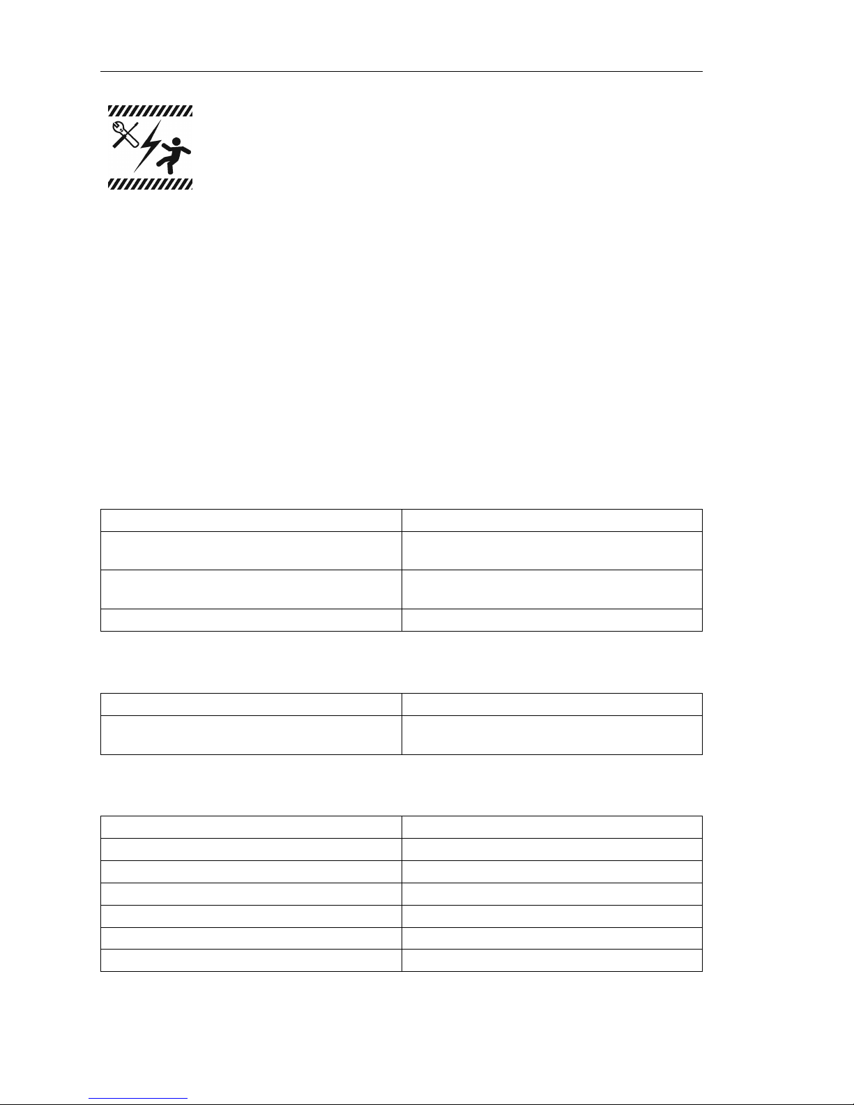
Do not ground the welder to electrical components such as the control
ground or sensors! Improper grounding can cause damage to electrical
components! Clamp the ground cable from the welder to the component
being welded. Place the clamp as close as possible to the weld to reduce
the possibility of damage.
1. Stop the engine. Turn the keyswitch to the OFF position.
2. Disconnect the negative battery cable from the battery.
3. Open any installed battery disconnect switch.
4. Unplug the control system if possible.
5. Connect the welding ground cable as close as possible to the area to be welded.
6. Protect the wiring harness from welding debris and spatter.
7. Use standard welding methods to weld the materials.
6.4 Control System Troubleshooting
Control system does not perform self-test
Possible Cause Possible Remedy
Tripped overcurrent protection
Faulty connection to battery
Faulty control system Repair or replace control system
Control system performs normal self-test, engine cranks, runs and shuts down
Possible Cause Possible Remedy
Engine Stop LED illuminated
Display does not display data
Possible Cause Possible Remedy
Display lost power
Engine Source address incorrect Change Engine Address in Configuration
Display Address incorrect Change Display Address to 40 (default)
Display configuration problem Reset display using Restore Defaults
CAN failure Check CAN (see Testing CAN)
ECU not sending data Repair or replace ECU
Correct fault, replace or reset overcurrent protection
Correct battery connections (see Battery Circuit
Requirements)
Correct ECU stop condition, use ECU diagnostics
Turn on key, verify display plugged into harness
Display shows Bad Device
Page 26 LOFA document No. 463-3002-22 Page 26
Page 32

6. Miscellaneous
Possible Cause Possible Remedy
Configuration file does not match firmware version
Reload configuration file from the config program with matching version
6.4.1 Testing a Warning or Shutdown
Shutdown simulation with ECU controlled engines requires using the ECU diagnostic tool. Refer to
the diagnostic tool documentation to simulate a warning or shutdown.
6.4.2 Testing CAN
Most information provided to the CANplus®display is sent by the ECU via the CAN bus. CAN is
an international data bus used to support SAE J1939. If this connection is broken or improperly
terminated, the CANplus®display cannot show ECU parameters such as engine hours, oil pressure
and diagnostic codes. This test procedure helps identify the problem location.
1. Disconnect the battery.
2.
Identify the engine diagnostic plug. Connect an ohmmeter across the CAN pins of the diagnostic
plug.
3.
A reading of 60±5Ω indicates both ends of the bus are correctly terminated and the bus is intact.
4.
A reading of 120±10Ω indicates only one end of the bus is terminated. (Note: The CP640c has
switchable termination via software. Please see CAN bus settings in the Tech menus for more
information.)
An ohmmeter reading of around 120Ω indicates the bus to the terminator in the panel is complete
and the problem is between the panel and the engine terminator.
An open circuit ohmmeter reading indicates the bus to the engine terminator is complete and
the problem is between the panel and the diagnostic plug.
5. Reinstall the terminator resistor and reconnect the battery.
If the ECU diagnostic tool is available, use it to verify the ECU is transmitting CAN data. Refer to
ECU documentation to identify and correct the error.
If another panel is available for testing, replace the panel to determine if the error is in the panel.
6.5 Diagnostic Trouble Codes (DTC)
CAN Diagnostic Trouble Codes are a pair of numbers; the SPN and FMI. The SPN indicates the
faulting subsystem and the FMI identifies the type of failure.
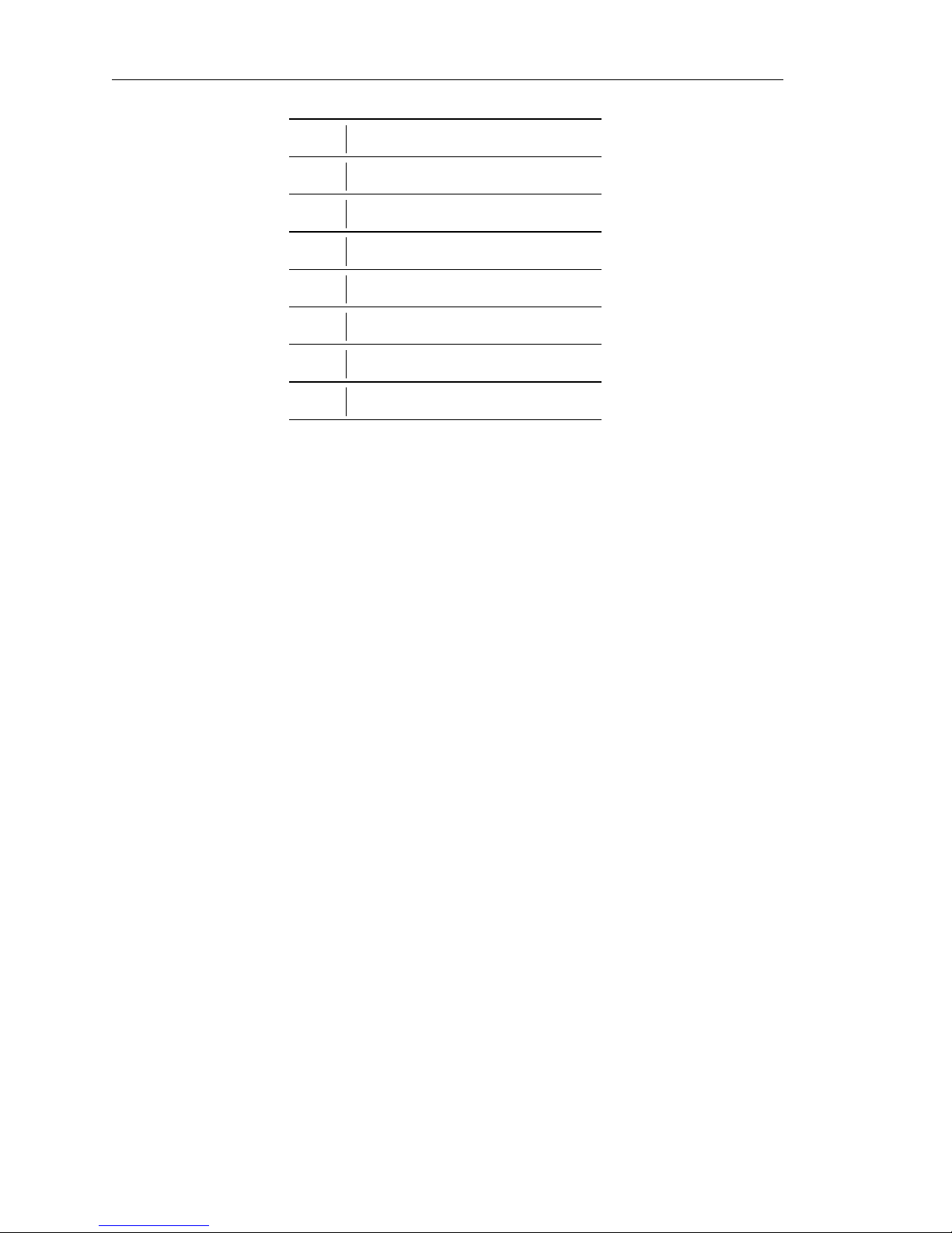
6.5.1 Typical SPNs
Standard SPN codes are defined by SAE J1939-71. Not all standard codes are provided by ECUs.
Manufacturers may add additional SPN codes beyond the codes identified in J1939-71. Refer to
ECU documentation for supported SPNs. Table 2 on the next page describes some example SPNs.
6.5.2 FMI
FMI codes are defined by SAE J1939-71. Refer to ECU documentation for correct interpretation of
FMI codes for a specific SPN. Table 3 on page 29 describes each FMI.
LOFA document No. 463-3002-22 Page 27
Page 33
6. Miscellaneous
SPN Description
51 Throttle Position
91 Accelerator Pedal Position
94 Fuel Delivery Pressure
98 Engine Oil Level
100 Engine Oil Pressure
110 Engine Coolant Temperature
111 Coolant Level
Table 2. Example SPN
Page 28 LOFA document No. 463-3002-22 Page 28
Page 34

FMI Description
0 Data valid but above normal operational range
1 Data valid but below normal operational range
2 Data erratic, intermittent or incorrect
3 Voltage above normal or shorted high
4 Voltage below normal or shorted low
5 Current below normal or open circuit
6 Current above normal or grounded circuit
7 Mechanical system not responding properly
8 Abnormal frequency, pulse width or period
9 Abnormal update rate
6. Miscellaneous
10 Abnormal rate of change
11 Failure mode not identifiable
12 Bad intelligent device or component
13 Out of calibration
14 Special instructions
15 Data valid but above normal operational range (least severe)
16 Data valid but above normal operational range (moderately severe)
17 Data valid but below normal operational range (least severe)
18 Data valid but below normal operational range (moderately severe)
19 Received network data in error
20
thru Reserved for future assignment
30
31 Not available or condition exists
Table 3. FMI Descriptions
LOFA document No. 463-3002-22 Page 29
 Loading...