

Page 1
Operating Instructions
3 2 9 6 1 0 2 0
TV
Individual 46 Compose Full-HD
Individual 40 Compose Full-HD
233–32961.020
+
+
Page 2

Contents
Remote Control – TV Functions ...............................................................3
Control unit front side of the device .......................................................4
Connections rear side of the device ........................................................5
Welcome ................................................................................................... 6
Scope of delivery ............................................................................................6
About this operating manual ..........................................................................6
TV set equipment ............................................................................................6
Trademarks .....................................................................................................6
Acknowledgements ........................................................................................6
Operating convenience with wizards ............................................................... 7
The wizards in overview ..................................................................................7
Info display and TV index ................................................................................7
For your safety ......................................................................................... 8
Environmental protection ........................................................................ 9
Initial installation ................................................................................... 10
Installing the TV set ......................................................................................10
Removing the protective foil .........................................................................10
Preparing the remote control unit .................................................................10
Connecting the TV set ...................................................................................10
Turning the set on/off ...................................................................................11
First installation wizard .................................................................................11
Positioning/aligning DVB-T antenna ..............................................................13
Operating convenience ..........................................................................13
General information on menu operation ........................................................13
The info display ............................................................................................14
The index in the TV set ..................................................................................14
TV menu – Overview diagram .......................................................................15
Radio menu – Overview diagram ..................................................................15
Daily operation ...................................................................................... 16
Select station ................................................................................................16
Select video source .......................................................................................17
Adjusting the sound .....................................................................................18
Adjusting the picture ....................................................................................19
Operation without remote control ................................................................. 19
Button functions ...........................................................................................20
Managing stations ................................................................................. 22
TV stations ...................................................................................................22
Put together – change favourites lists ...........................................................24
Picture in Picture .................................................................................... 26
Picture in Picture (PIP) ..................................................................................26
Configure Picture in Picture (PIP) mode .........................................................27
- 2
Electronic Programme Guide ................................................................. 28
Electronic Programme Guide – EPG ...............................................................28
Configuring EPG ........................................................................................... 29
Teletext ................................................................................................... 30
Teletext ........................................................................................................30
Teletext menu ...............................................................................................31
DVB ......................................................................................................... 32
Conditional Access Module (CA module) .......................................................32
Software update ...........................................................................................33
Radio ...................................................................................................... 34
Radio mode .................................................................................................34
EPG – Electronic Programme Guide (radio) ....................................................34
Operating additional equipment ........................................................... 35
Device connection wizard .............................................................................35
Connecting devices to the HDMI (DVI) connections and playback ..................37
Connecting devices to the PC IN connection and playback.............................37
Connecting devices to the Component IN connection and playback ...............38
Sound components wizard ............................................................................39
TV speakers ..................................................................................................39
Speaker system Loewe Individual Sound on the Dolby Digital Decoder
of the TV set .................................................................................................40
Connecting other speaker systems or active speakers to the Dolby Digital
Decoder .......................................................................................................41
Adjusting the speaker system ........................................................................41
Connecting audio amplifiers .........................................................................44
Assignment of the digital audio input ...........................................................45
Audio connection in HDMI (DVI) devices .......................................................45
The direct way to record ...............................................................................46
Timer recording with external devices ............................................................47
PhotoViewer .................................................................................................48
Operating Loewe equipment .........................................................................50
Rotating the TV set .......................................................................................51
Troubleshooting ..................................................................................... 52
Technical data ........................................................................................ 54
General data ................................................................................................54
Electrical data ..............................................................................................54
Connections .................................................................................................54
Accessories ............................................................................................. 55
Accessories ...................................................................................................55
Setup possibilities .........................................................................................55
Glossary .................................................................................................. 56
Index ...................................................................................................... 59
Service .................................................................................................... 60
Please fold out this page.
Page 3
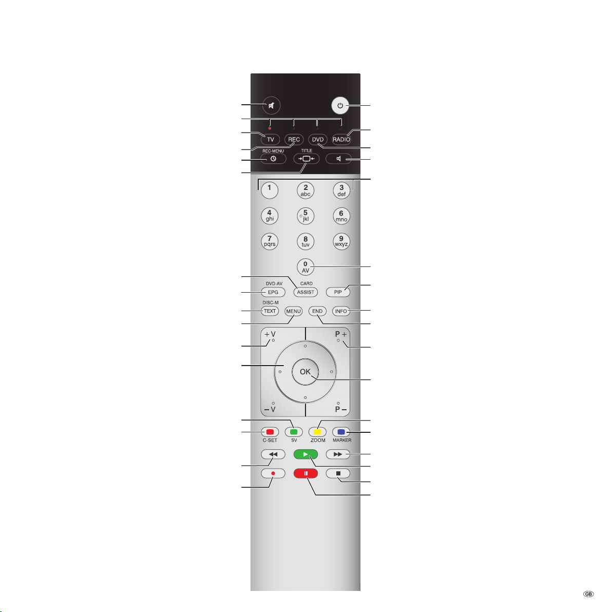
Remote Control – TV Functions
(Page 18) .............................................................. Sound off/on
(Page 50) .....................LED display for current operating mode
(Page 10; page 50) .............................Switch over to TV mode
(Page 50) .................................Switch over to operate recorder
(Page 47) .................................................Timer overview on/off
(Page 20) .......................................................Set picture format
(Page 20) ....................................................
Assist+ menu on/off
(Page 28) ........................... Electronic Programme Guide on/off
(Page 30) .............................................................Teletext on/off
(Page 13) ...............................................................Menu on/off
(Page 18) ......................................
(Page 27) ...................................
(Page 13) ........................................................
V+/V– volume louder/quieter
PIP: Position of the PIP picture;
MENU: select/set
Switch on/off
– to standby mode ..................................................(page 11)
Switch over to radio mode
(1
.....................(page 11; page 34)
Switch over to operate DVD player ..........................(page 50)
Set sound mode (page 18)
Select station directly;
MENU: Enter numbers or letters ..............................(page 16)
AV selection .............................................................(page 17)
PIP on/off (picture in picture)
....................................(page 26)
Index on/off
MENU: Info texts on/off ...........................................(page 14)
Status display on/off ................................................(page 21)
MENU: Hide menu
...................................................(page 13)
P+/P– select station up/down ..................................(page 16)
Station list on .....................................................(page 16)
MENU: confirm/call ..................................................(page 13)
(Page 20) ..........................................................Teletext subtitles
Green button:
Red button:
(Page 20) ............................................................Call DR archive
Digital Recorder:
Jump back/Rewind/Replay
(Page 11) ..................................................../in the wizard: Back
Direct recording
Yellow button: Last station ......................................(page 20)
Blue button: Programme info on/off .......................(page 20)
(2
Digital Recorder: Jump forward/Fast forward
Digital Recorder: Play/Set bookmark
Digital Recorder: Stop (live picture)
(2
Digital Recorder:
Freeze picture/Pause (start offset TV viewing)
(1
Radio only for DVB reception, provided the station broadcasts this.
Otherwise switch-over to an audio input.
(2
Description of the functions, see operating manual Digital Recorder.
(2
(2
(2
3 -
Page 4
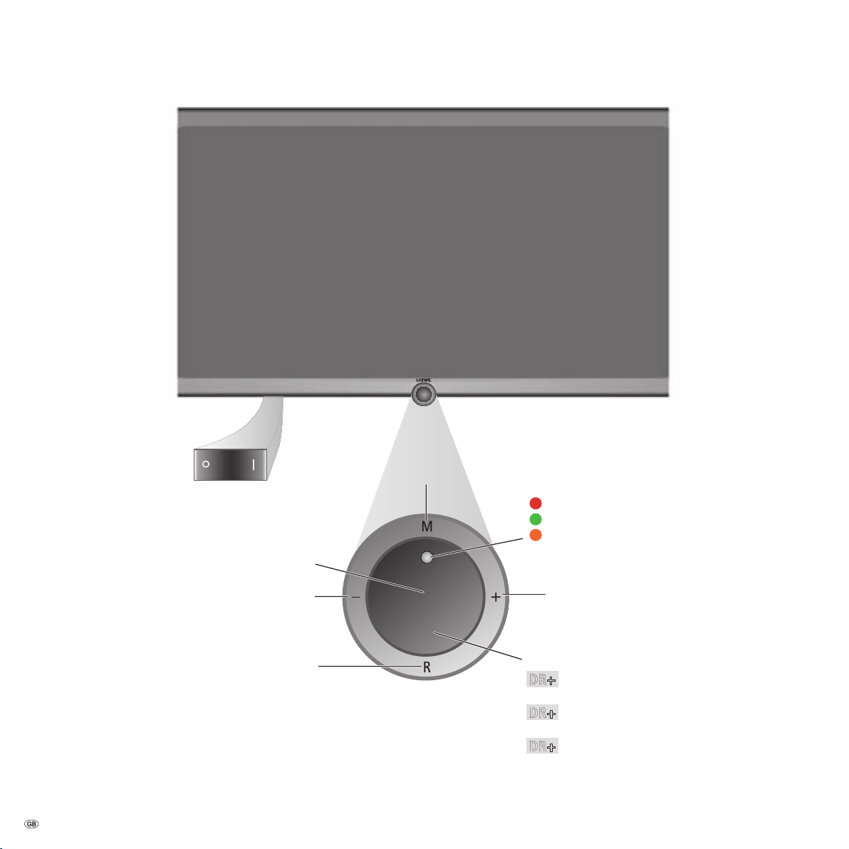
Control unit front side of the device
DR+
Button +:
Station up
in the menu: to the right
On/Off button:
Switch on from the standby mode
Switch off from the standby mode
Button – :
Station down
in the menu: to the left
Display:
= Standby
= Operation
= Operation without on-screen display
(Radio, EPG data capture or timer recording)
Button R:
Radio on/off(1 (back to TV mode).
Switch on the radio from the standby mode
in the menu: down
Button M:
Call the menu
in the menu: up/down
The mains switch is
on the bottom of the TV
DR+ = Digital Recorder integrated, but inactive
(no recording, no playback)
DR+ = Digital Recorder active (offset TV viewing
or archive playback)
DR+ = Digital Recorder active
(archive recording)
Display DR+:
(1
Radio only for DVB reception, provided the station broadcasts this.
Otherwise switch over to an audio input.
- 4
Page 5
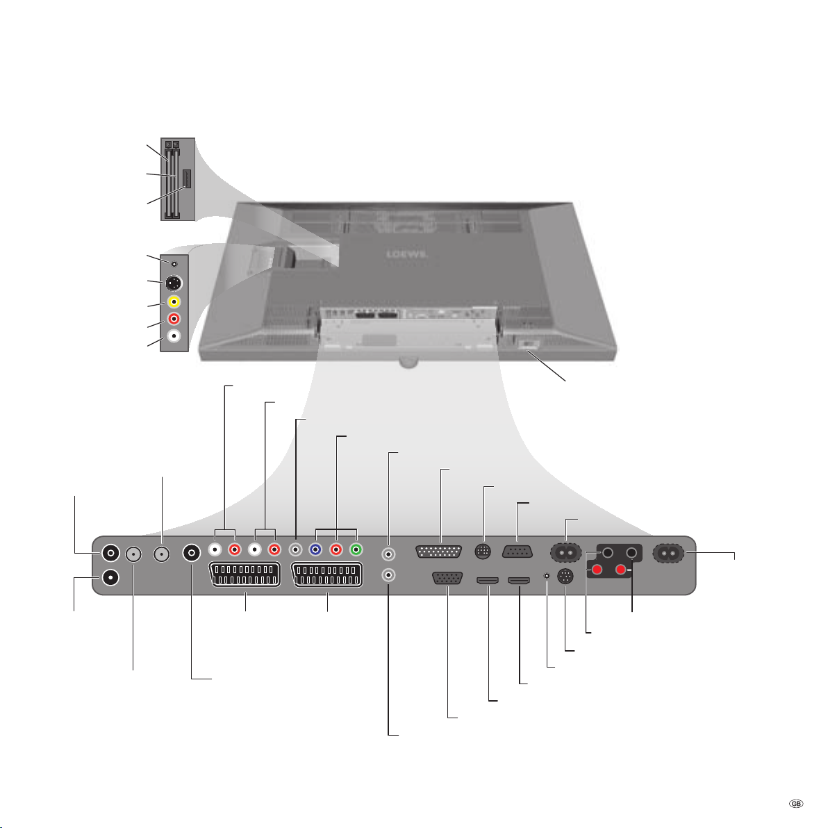
Connections rear side of the device
ANT OUT
Connect antenna
output with ANT-TV
(tuner 1)
ANT-TV
Antenna/cable
analogue/digital
(Tuner 1)
mains switch
CONTROL - rotating stand control
RS-232C - serial interface
AUDIO IN1 L/R - audio input left/right (analogue)
AUDIO OUT L/R - audio output left right (analogue)
ANT SAT2
Satellite antenna
(Sat tuner 2)
ANT2
Antenna/cable
analogue/digital
(Tuner 2)
AV1
Euro-AV
socket 1
AV2 (RGB)
Euro-AV
socket 2
220-240V~ 50/60Hz
mains connection
(2
SERVICE - service socket
PC IN - VGA-/XGA input
HDMI2 - HDMI (DVI) input 2
AUDIO DIGITAL IN - digital audio input
AUDIO DIGITAL OUT - digital audio output
SD/HD-COMPONENT IN Cb/Pb–Cr/Pr–Y - component video inputs
Headphones connection
Common Interface 1
(CI-Slot 1)
S-VHS connection (AVS)
(e.g. for camcorder)
Video in (AVS)
Audio in right (AVS)
Audio in left (AVS)
AUDIO IN1 C - centre audio input (analogue)
AUDIO LINK - surround audio outputs (analogue)
HDMI1 - HDMI (DVI) input 1
USB connection
(USB stick/card reader)
ANT SAT
Satellite antenna
(Sat tuner 1)
AUDIO IN2 - audio input (analogue)
Speakers Right (+/-) - Speakers Right (+/-)
Speakers Left (+/-) - Speakers Left (+/-)
Common Interface 2
(CI-Slot 2)
220-240V~ 50/60Hz - mains connection
(1
Factory settings:
AV1: DVD player
AV2: DVD recorder
You can change this during the
initial installation (page 11) or in
the
connection wizard (page 35).
Before you connect other devices
or make any changes, please start
the
connection wizard (page 35)
and the
sound components wizard
(page 39), and then follow the
instructions that are displayed on
the TV set.
(1
mains connection for Individual Compose 40.
(2
mains connection for Individual Compose 46.
5 -
Page 6

Welcome
VIRTUAL SPEAKER
SU RR OU ND
D I G I T A L
C
®
S
®
T
®
Thank you!
At Loewe, we combine the highest standards of technology, design and
user friendliness. This applies equally for TV, video and accessories.
Your new TV set is equipped for the TV standard "HDTV"
(High Definition Television). With its high resolution screen
and future-safe digital interfaces HDMI (High Definition
Multimedia Interface), it offers the possibility of present
ing HDTV programmes in outstanding picture quality.
HDTV is a worldwide, digital standard in the 16:9 format
which revolutionises normal TV viewing. It is broadcast
with an up to five times greater resolution than conven
tional signals and therefore creates an unexpectedly 3D
image.
The TV set is equipped for digital reception. You can use the already
frequently broadcast "everywhere television" (DVB-T) as well as digital
cable (DVB-C) and digital satellite reception (DVB-S).
The Loewe Digital
DVB-C and DVB-S.
The TV set is equipped with a Dolby Digital Decoder. You can connect
a speaker system (e.g. Loewe Individual Sound) or active speakers and
enjoy movie theater sound.
You can connect a card reader or a USB stick with digital photos to your
new TV set's USB connection and view your photos via the integrated
PhotoViewer software.
All the functions can be operated with the Loewe remote control.
We have designed the TV set in such a manner that you can easily
operate it with the help of wizards and menus. Information about the
menu settings is displayed automatically. You will quickly comprehend
the context.
+
HD platform even allows dual reception of DVB-T,
Scope of delivery
LCD-TFT TV set
•
Mains cable
•
Wall mount WM54 (incl. installation instructions)
•
Remote control Assist with two batteries
•
Marketing and service card
•
Operating instructions of the Digital Recorder
•
This operating manual
•
No speakers are included in the scope of delivery for the "Individual
Compose" TV set. You can custom configure the speaker equipment
with your TV set and adapt it to your requirements. Ask your dealer in
this regard.
About this operating manual
For many questions concerning the technology you will find an answer
in the index of your TV set. If your question concerns TV set operation,
you can access a function directly from the index of the TV set. Owing to
this possibility, this operating manual only explains the most important
operating steps.
The index/glossary from page 56 onwards gives explanations of certain
terms used in the TV set and the operating manual.
Paragraphs beginning with the symbol
or conditions for trouble-free operation.
-
Terms which you will find in the menu or printed on the TV are written
bold type.
in
In the functional descriptions, the necessary operating elements are ar-
ranged to the left of the text containing the handling instructions.
➠ indicate important hints, tips
TV set equipment
See the rating plate on the rear of the set for the precise product designation. The precise features are listed in the
the index of the TV set (see page 14).
Integrated features item in
Trademarks
"Dolby", "Pro Logic" and the double D symbol are protected trademarks
of Dolby Laboratories Inc. "DTS" and "DTS Digital Surround" is a trademark
of Digital Theater Systems Inc.
The screen font "LoeweL2700" is based on the "Tavmjong Bah Arev
(tavmjong.free.fr)" font, which in turn is based on "Bitstream Vera".
Bitstream Vera is a trademark of Bitstream Inc.
Acknowledgements
Loewe Opta GmbH
Industriestr. 11
D-96317 Kronach
www.loewe.de
Printed in Germany
Date of issue 01/07-1.0 Be/Ps
TV–SW: 0.26.1 / DVB–SW: 0.18.5
© Loewe Opta GmbH, Kronach
All rights including translation, technical modifications and errors
reserved.
- 6
Page 7

Welcome
END
OK
P+
P–
OK
a
z
-
Activate Previous/next letter
Select letter Page ↓↑
Index
Language
Integrated features
Repeat initial installation
*
Access code
ASSIST+
Automatic dimmer
Automatic station programming
You can select your language for operating the TV set.
Operating convenience with wizards
This TV set offers user prompting with wizards that take you through the
settings step-by-step.
You can return to the previous step or exit the wizard at any time.
The wizards in overview
Initial installation
The initial installation wizard helps you with the initial installation and
connection of any existing equipment (see page 11).
Setting up the antenna
You enter in the antenna wizard which antenna signals are available to
you. The antenna wizard is called in initial installation (see page 11). You
can also call the antenna wizard in the TV menu under
Antenna DVB
→ Antenna DVB-S or Antenna DVB-T.
Search wizard
If you want to search for new stations after the initial installation, or if
you have set up your antenna for the first time, then you can handle this
task with the help of the search wizard (see page 22).
Connecting external devices
The connection wizard ensures that all devices are correctly registered
and connected. It is started automatically at the end of the initial instal
lation wizard but can also be called separately (see page 35).
Connections →
Programming and managing recordings
The recording wizard can be called quickly via the timer overview and
helps you to program a video recording with a video recorder, DVD re
corder, or the integrated Digital Recorder (see page 46).
Station list
The station list is a list of all stored stations. You can also use the station
list for switching stations conveniently (see page 16).
Software update wizard
The latest software for your TV set can be loaded via satellite or via USB
stick (see page 33).
Info display and TV index
An information display for each menu item
The info display automatically shows content-based info texts in the
upper part of the screen for each menu item. It forms a convenient
operating system with the
An index in the TV set
The index gives you an overview of the functional scope of your TV set. You
can also start wizards and menu settings directly from here (see page 14).
-
index (see page 14).
-
Connecting sound components
The sound component wizard ensures that the components which re
produce the TV sound are correctly registered, connected and set. It is
started automatically at the end of the initial installation wizard but can
also be called separately (see page 39).
Assist+
You can select the most important modes directly via a menu. Digital Re
corder Archive,
Pages can be selected (see page 20).
Radio, Favourites, PhotoViewer, Index and Personal Text
-
-
7 -
Page 8
For your safety
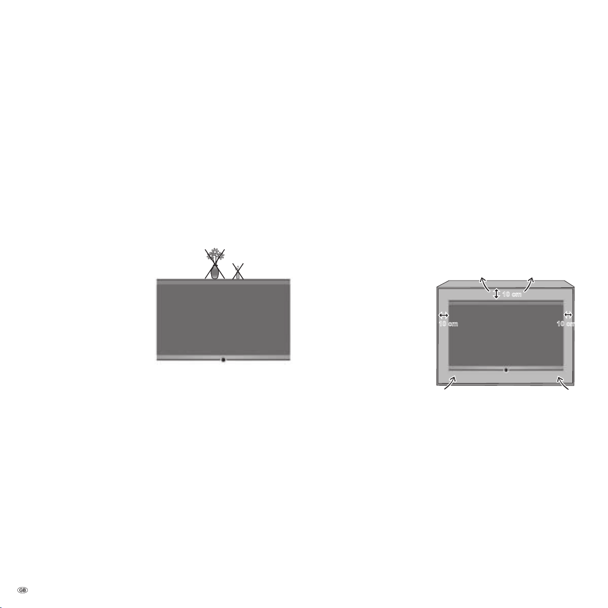
10 cm
10 cm 10 cm
For your own safety and to prevent unnecessary damage to your device,
read and comply with the following safety instructions:
Proper use and environmental conditions
This TV set is designed exclusively for reception and reproduction of
video and audio signals and is designed for living rooms or office facilities,
and should not be operated in rooms with high
bathroom, or sauna, or where there is a high
workshops).
If the set is used outdoors ensure that it is protected against
(rain, splashing water, or dew). High humidity and dust concentrations
cause leak currents in the device, which can cause a shock hazard if the
device is touched, or a fire.
If you have brought the set into a warm environment from the
wait for about 1 hour before switching it on to avoid formation of
densation.
Do not place any
with
liquid or burning candles on
the device.
The manufacturer‘s warranty is
only valid for use in the specified
permissible environment.
Do not install the TV where there
may be
to material overload.
Transporting
Only transport the device in
upper and lower edges of the housing. Never set the TV down on the
protruding control unit on the bottom of the TV set. This could damage
the control unit.
If the set has to be put down during packing/unpacking, place the TV
set with the entire front surface lying flat on a soft underlay such as a
blanket or the felt from the packing material.
The LCD screen is made of glass or plastic and can break if not handled
properly.
If the LCD screen is damaged and
gloves when moving the device. In the case of
wash thoroughly with water.
vibrations. This can lead
objects filled
vertical position. Grasp the device on the
liquid crystal escapes, wear rubber
humidity, such as a
concentration of dust (e.g.
skin contact immediately
moisture
cold, then
con-
Power supply
The
wrong voltage can damage the set. This equipment must only be
connected to a mains power supply which has the same voltage and
frequency as that specified on the rating plate; use the mains cable
provided. The
the device can be disconnected from the mains at any time. When you
unplug the mains plug, do not pull on the
housing. The cable in the mains plug could be damaged and cause a
short circuit the next time it is plugged in.
Lay out the
The mains cable must not be kinked or laid over sharp edges, stepped
on or exposed to
ment. A mains cable with damaged insulation can cause
and is a
Air circulation and high temperatures
The
vent slots on the rear panel of the set must always be kept free.
Please do not place newspapers or cloths on/over the TV.
Ensure that there is at least 10
cm free space on the sides and
above the set for air circulation,
if the set is placed in a
or on a
Like any electronic device, your
TV set requires air for cooling.
Obstruction of the air circula
tion can cause fires.
The set is suitable for different
installation solutions. See the
instructions for assembly for the different installation solutions.
Stand the TV set with the table or floor stand only on a level,
horizontal base. Particularly ensure that the set does not protrude to the
front when placed in or on pieces of furniture.
Set up the device where it is not exposed to direct
is not exposed to additional warming through
Prevent
from getting into the interior of the device through the
rear panel. Such objects can cause
possibly cause a fire.
If something should get into the
unplug the mains plug of the device and contact
more information.
mains plug of the TV set must be easily accessible so that
cable rather pull on the plug
mains cable in such a manner that it cannot be damaged.
chemicals; The latter also applies for the entire equip-
electrical shock
fire hazard.
cabinet
shelf.
-
sturdy,
sunlight and where it
heating elements.
metal items, needles, paper clips, liquids, wax, or similar items,
vent slots in the
short circuits in the set, which could
interior of the set then immediately
customer service for
- 8
Page 9
For your safety
Environmental protection
Repairs and accessories
Never remove the back of the TV set yourself. Only have your TV device
repaired or serviced by
Only use
cessories on page 55).
Supervision
Do not allow
the immediate vicinity of the TV set. The set could tip over, be pushed
off or pulled down from the stand surface and injure someone.
Do
Volume
Loud music can lead to ear damage. Avoid extreme volume especially
over long periods and when using headphones.
Cleaning
Clean the TV set, the screen, and the remote control unit with a soft,
moist, and clean cloth,only,
agents.
Thunder storms
Pull out the
set in a thunderstorm. Overvoltage caused by
set via the antenna system, as well as via the mains. The mains plug and
all connected antenna cables should also be pulled out during long pe
riods of
Note on the LCD screen
The TV set you have purchased with LCD screen satisfies the most rigor
ous quality requirements and has been inspected relative to
In spite of the utmost care in manufacturing the display, for technical
reasons the possibility that some
excluded. Please understand that these types of effects, as long as they
are within the standard of specified limits, cannot be considered as a
device defect in terms of the guarantee.
original accessories such as Loewe stands if possible (see Ac-
children to use the TV set without supervision or to play in
not allow the switched-on TV set to run unattended.
mains plug and all connected antenna cables from the TV
absence.
authorised television technicians.
without any aggressive or scouring cleaning
lightning can damage the
pixel errors.
pixels will have defects cannot be 100%
Energy consumption
Your TV set is equipped with an eco-standby power supply. In the standby
mode, the power consumption drops to low power (see technical data on
page 54). If you want to save even more energy then switch the device
off with the mains switch. However note that in this case, EPG (Electronic
Programme Guide) data will be lost, and it may be that programmed
timer recordings
Packaging and box
You have made a decision to purchase a high-quality technical product
with a long service life. For disposal of the packaging, in accordance with
national legislation we have paid a fee to a commissioned recycler to pick
up the packaging from the dealer.
the original box and
be transported with optimal protection if necessary.
The set
recycling centres or at your specialist dealer whenever you purchase a
new, comparable set. Additional details about return (also for non EU
countries) are available from your local municipal authorities.
-
Batteries
-
cannot be executed via the TV device.
Nevertheless we recommend keeping
packaging material on hand so that the device can
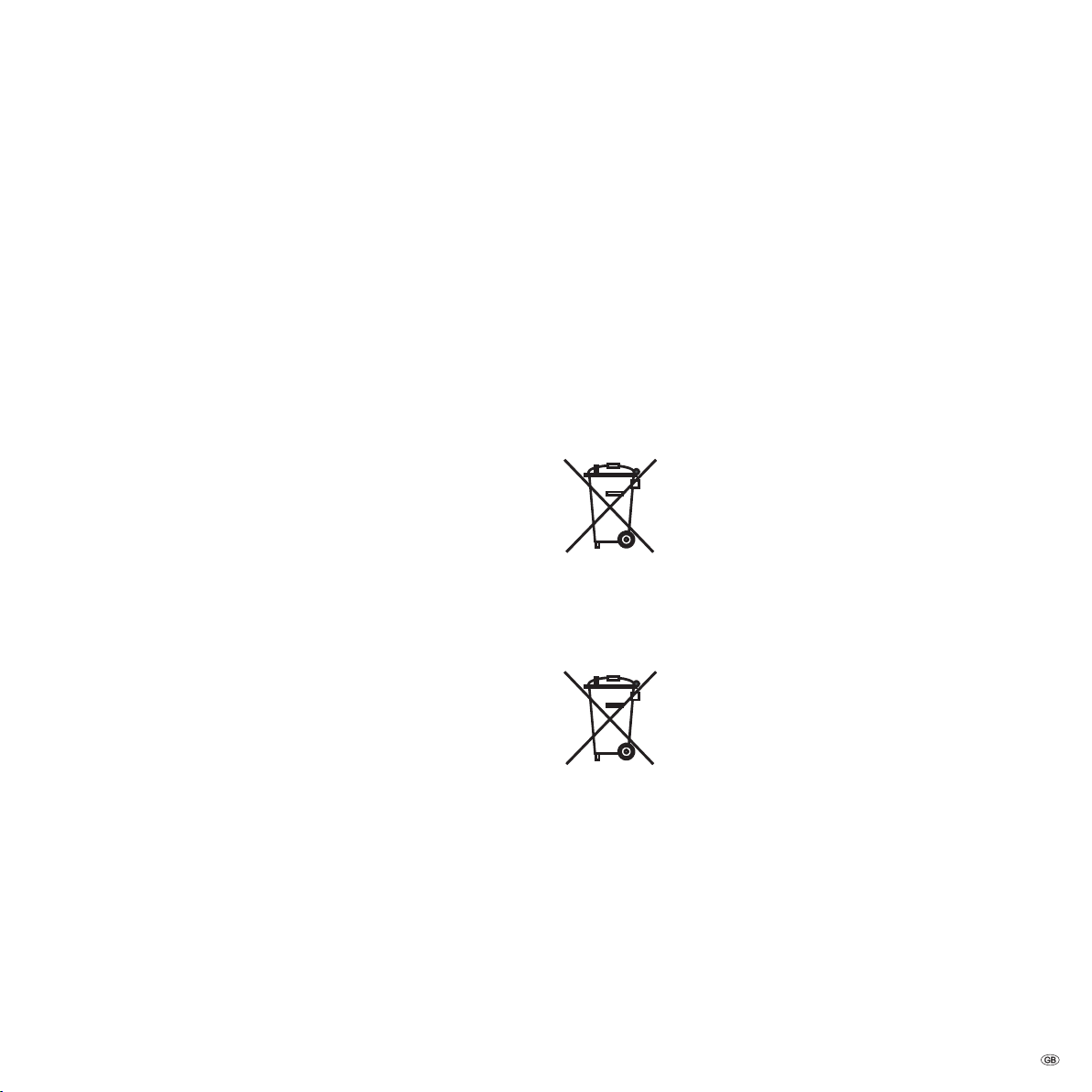
The EU directive 2002/96/EC regulates the proper way
to recycle, handle and utilise used electronic devices.
Old electronic devices consequently must be disposed of
separately. Please do
household trash!
You may return your used set free of charge at designated
The batteries supplied as initial equipment do not contain
any pollutants such as cadmium, lead, or mercury.
Used batteries should
mestic waste according to the Battery Ordinance. Dispose
of your batteries at no charge in the
which are set up for this purpose in retail stores.
not dispose of this device in normal
no longer be disposed of in the do-
collection containers
9 -
Page 10
Initial installation
TV
R
AAA LR03
AAA LR03
Installing the TV set
First prepare the chosen installation solution for your TV set. See the
installation instructions of the wallmount supplied. See Accessories (page
55) for other installation possibilities.
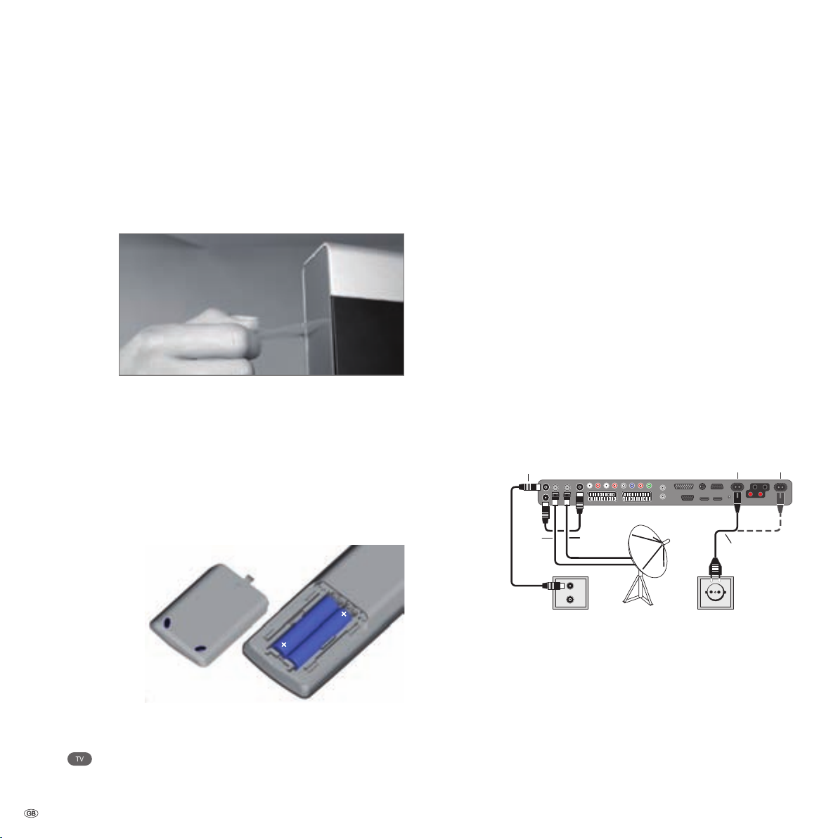
Removing the protective foil
Slowly and carefully remove the protective foil on the trim.
Preparing the remote control unit
Inserting or replacing batteries
Press the embossed arrow and push down the
battery compartment cover.
Insert two alkaline manganese LR 03 (AAA) batteries;
ensure that the + and – poles are correctly positioned!
Slide the cover up from below.
Connecting the TV set
Connecting to the mains
➠ Note the position of the mains connection in
Individual Compose 40 / 46.
Remove the cover for the connections.
Connect the TV set to a 220-240V outlet:
First plug the small plug of the mains cable into the
mains connection on the rear of the TV, then plug the
large plug into a mains power outlet.
Connecting the antenna
Analogue / DVB-C / DVB-T antenna:
Plug the antenna plug of antenna system, cable system,
or room antenna into the
The connecting cable between
plugged at the factory.
Satellite antenna:
Connect an antenna plug, e.g. from the antenna changeover switch or from the twin-LNC of the satellite system
to the sockets
When connecting only one SAT antenna cable, connect
it to
ANT-SAT.
ANT2
ANT
SAT2
ANT
SAT
ANT2 socket.
ANT-TV – ANT OUT is
ANT-SAT and ANT-SAT2.
Individual Compose: 40 / 46
220-240V~
50/60Hz
Adjusting the remote control for operating the TV set
Press the
See page 50 to learn about operating other Loewe
TV button.
devices.
- 10
Connections on the back of the set (see also page 5).
Replace the cover over the connections.
Connecting speakers
How to configure and connect TV speakers, speaker
systems or active speakers is described from page 39.
Receiving coded stations
When using a CA module and a Smart-Card to receive
coded stations, please observe the handling of the CA
module (see page 32).
Page 11
Initial installation
OK
OK
First installation wizard
Which language do you want to use for operation?
Initial installation
Language
Sprache D Kieli SF
Language GB Jezik SLO
Langue F Jazyk SK
Lingua I Lisan TR
Idioma E Språk S
Taal NL Sprog DK
Jazyk CZ Idioma P
Γλώσσα
GR Язык RUS
Język PL Språk N
Nyelv H
Proceed
Initial installation
Connect antenna cable(s)
Antenna cable(s) for: to antenna socket(s):
Antenna/cable (analogue) ANT TV
DVB-T ANT TV
DVB-C ANT TV
DVB-S (cable 1) ANT SAT
DVB-S (cable 2) ANT SAT2
Connect/disconnect
Proceed Back
OK
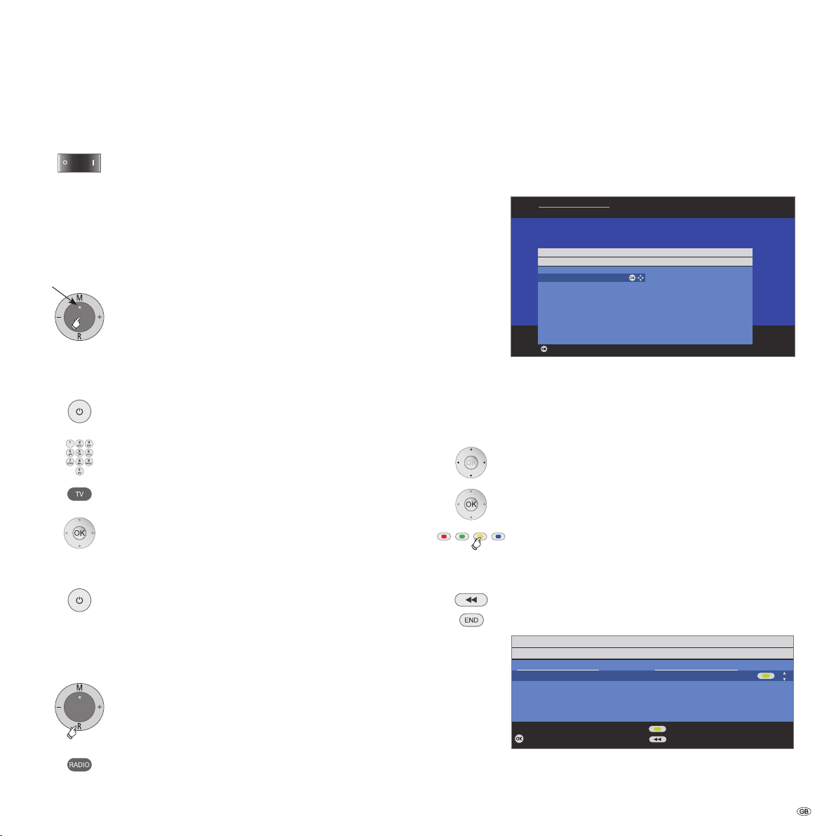
Turning the set on/off
Switching the TV set to standby mode
Activate the mains switch on the bottom left of the set.
The display in the control panel on the front of the set
will be illuminated red, the set is now in standby mode.
Switching the TV on/off on the control unit
Press the on/off button in the middle for about 2 seconds
Display
Switching the set on with the remote control
Switching the set off with the remote control
to switch the TV set on/off.
Meaning of the display colour:
Red: Standby mode
Green: TV set is switched on
Orange: Radio mode, TV set receives EPG data or timer
recording active
Press the
on/off button.
or:
numeric buttons (0–99).
or:
TV button.
or:
OK button – station list is called.
Press the
on/off button.
➠ Before switching off the set with the mains switch, we
recommend you to switch it to standby mode.
First installation wizard
First installation after switching on for the first time
This wizard starts automatically after the set is switched on for the first
time, however it can also be called later manually in the TV
Repeat initial installation on page 14.
The first step with the wizard starts when selecting the
language for the user prompts. From this point on follow
the instructions on your TV set.
Brief explanation of button functions:
Press the ring (up, down, left, right) to move the cursor
and to select settings.
By pressing the
OK button a setting is confirmed and you
will go to the next step.
You can select or remove several items with the
button (see example below).
When an element is selected, it is marked by a
checkmark
.
Use this button to go back one step.
Exit the wizard with the
END button (if available).
index, see
yellow
Switching on/switching to radio mode
Press
R on the TV control unit.
or:
RADIO button on the remote control.
(radio mode, see page 34).
An example of multiple selection using the
continued on the next page
yellow button.
11 -
Page 12

Initial installation
Explanations of the setting possibilities:
Location
of TV set
Antenna
selection
Antenna
DVB-C:
Settings
Satellite
system
High band
frequencies
Low Band /
High Band
Symbol rates
Favoured
signal source
Select the country for country-specific pre-settings.
Antenna/cable (analogue):
cable/antenna
DVB-T: digital, terrestrial stations
DVB-C: digital stations via cable
DVB-S (line 1): digital stations via satellite
DVB-S (line 2): digital stations via satellite
If you are using an active antenna, then select
DVB-T:
for the antenna power supply.
The conventional settings will be derived from the selec
tion of set location. Only change this if you know other
symbol rates and modulation types or if you have to spe
cify the network ID for your cable network (information
available from your cable network provider). If you want
to run the station search independently of the channel
grid, select frequency search for the search method.
Select which satellite(s) you receive from a list. For more
DVB-S:
than one satellite, select the type of your changeover
switch or communal satellite system additionally.
Ask your dealer in this regard.
Specify here whether the high band of the selected satel
lite is to be searched in addition to the low band.
Normally, you do not need to change the values for high
LNC
and low band, unless the LNC (LNB) of your satellite
system uses a different oscillator frequency (important
for the frequency display).
After you have made these settings, you should receive
the picture and sound of the selected satellites (only with
Astra1 and HOTBIRD).
The symbol rates are specified by the satellite provider
and normally do not need to be changed.
Select the signal source that provides the stations to be on
top of your station list (starting with station slot 1).
analogue stations via
yes (5V)
Start search
Connecting
additional
devices
-
-
Digital Link
-
Explanations of the DVB-T antenna:
antenna
antenna
Unidirectional
antenna
Start the automatic station search with OK.
First TV stations, then radio stations are searched for.
The stations found in the automatic search are divided
into the appropriate station blocks depending on the
previously selected antenna cables (signal sources). Sub
sequently the stations can only be re-sorted within these
blocks. At the beginning of the station list you will find the
block with the stations of the preferred signal source.
Any mixed sorting of stations from different signal sources
is only possible with the favourites list.
In conclusion the connection wizard and the sound com
ponents wizard will start; with their help you can register
and set your video devices, decoders, speaker system,
or a HiFi/AV amplifier and connect them to the TV set.
DVD players and DVD recorders are already registered
at the factory.
You can start the connection wizard and the sound
components wizard manually later and add new devices.
Further information is available from page 35 (Connection
wizard) and page 39 (Sound components wizard).
If you have registered and connected a recorder in the
connection wizard, the Digital Link Plus transmission
Plus
begins at the end of the sound components wizard. If
a Digital Link Plus capable recorder is connected, the
station list of the analogue stations is transmitted to the
external recorder.
You can also call Digital Link Plus under
nections → Digital Link Plus.
If you have not connected a Digital Link Plus capable
recorder, you can abort the transmission.
Room
With good reception conditions a room antenna can be
used for DVB-T (socket
Active
Under less favourable reception conditions, it is advisable
to use an active antenna which has to be set accordingly
in the initial installation or in the
→ Antenna DVB → Antenna DVB-T (see DVB-T antenna
on this page).
If the location is outside of the normal transmission
range then a directional antenna can be used to improve
reception quality.
-
-
TV menu → Con-
ANT2).
TV menu → Connections
- 12
Page 13
Initial installation
END
INFO
Sound
Connections
Recording SettingsPicture
TV menu
Picture adjustment ...
Picture
Here you can adjust among other things: Contrast, colour, brightness, picture
adjustment, sharpness, picture format.
END
INFO
Manual adjustment
Signal source DVB-T DVB-C DVB-S A
Channel E05
Frequency 177.50 MHz
Bandwidth 7 MHz
Name 12 Test
C/N 96 Level 99
Overwrite station
Search
Signal source
Select the area in which you want the broadcaster to search here. You can
use the button to automatically select station by station.
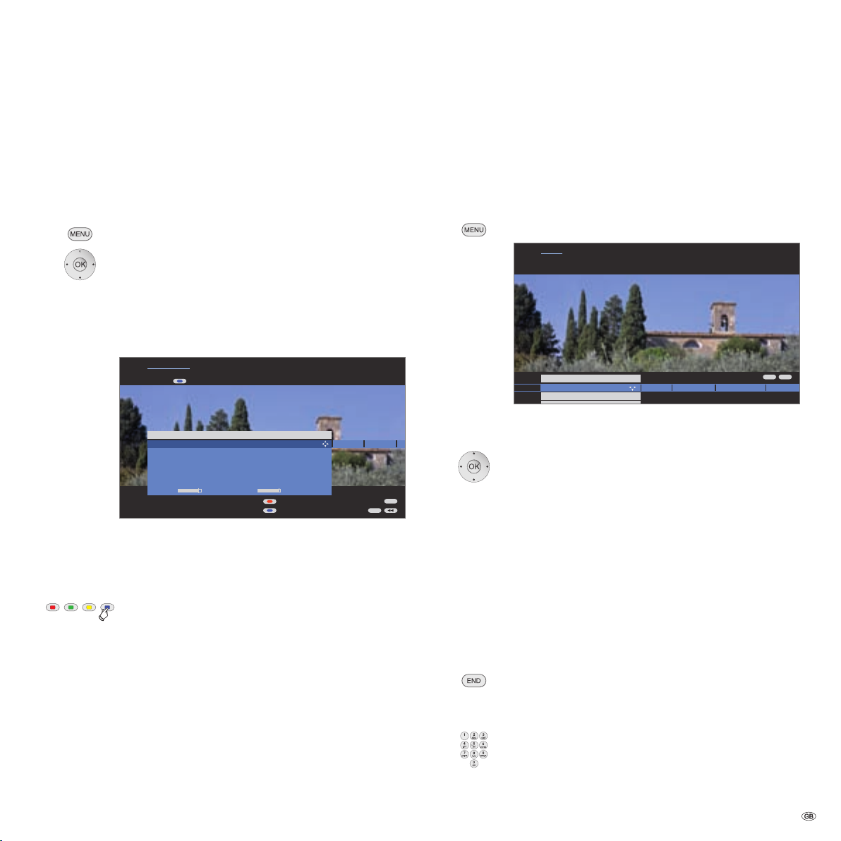
Operating convenience
Positioning/aligning DVB-T antenna
If you are receiving one or more DVB-T stations with picture and sound
interference then you should change the installation location and align
ment of the antenna. Ask your dealer to tell you which channels are used
to broadcast the DVB-T stations in your region.
➠ In normal TV mode, without other displays.
A DVB-T station is received and selected.
Call
TV menu.
34 Select Settings,
6go to the menu line below.
34 Select Stations,
6go to the menu line below.
34 Select Manual adjustment,
OK call manual adjustment.
The signal source is already on DVB-T due to the station
preselection.
Position and align the antenna in such a manner that
maximum values for
Blue button: Start search.
Search for DVB-T stations one after another and compa
re values for
Then position/align the antenna to the weakest station
so that maximum values for
Thereafter perform an automatic search for all DVB-T
stations, see page 22.
Explanation of the setting possibilities:
Bandwidth
Depending on the selected channel and country the
associated bandwidth of 7 or 8 MHz will be set auto
matically.
C/N and Level are obtained.
C/N and Level.
C/N and Level are obtained.
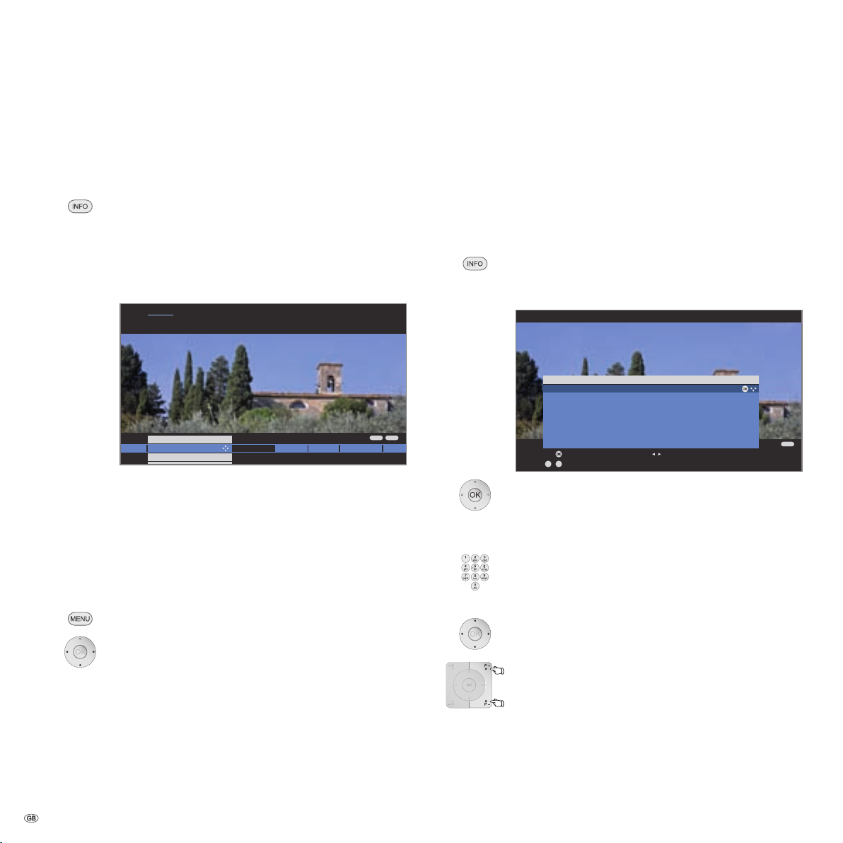
General information on menu operation
Use the MENU button to call menus for the various modes. Additional
menus can be called directly with the remote control.
The menus are displayed at the bottom of the screen. At the top you get
additional information about the selected menu item (see info display
on page 14).
➠ In normal TV mode, without other displays.
Call
TV menu.
Example: Selecting and executing functions
34 Select Picture,
6go to the menu line below.
34 Select Brightness,
6go to the menu line below.
34 Set Brightness.
Go to the Brightness menu line
to make other picture settings.
34 Select more ... ,
OK call more ... functions.
-
Inputs via numeric buttons
-
34 Select Auto format,
6go to the menu line below.
34 Select on / off.
Conclude the settings.
Letters have to be entered for specific functions. Like
using a mobile phone keypad (1 to 9), press a numeric
button until the desired character appears.
The available letters are imprinted on the individual
numeric buttons.
13 -
Page 14
Operating convenience
END
INFO
SoundPicture
ConnectionsRecording
Settings
TV menu
Settings
Here, you can search for the stations automatically or manually as well as set
the menu language, timer functions, parental lock, on-screen displays, etc.
Stations ...
END
OK
P+
P–
OK
a
z
-
Activate Previous/next letter
Select letter Page ↓↑
Index
Language
Integrated features
Repeat initial installation
*
Access code
ASSIST+
Automatic dimmer
Automatic station programming
You can select your language for operating the TV set.
The info display
The info display shows a content-based info text for each menu item at
the top edge of the screen to help you in making the settings. In conjunc
tion with the index it creates a convenient control system.
➠ A menu is displayed.
The factory setting makes the info display appear auto
matically for each menu item. In this case you can
temporarily hide the info texts with the
The automatic info display can be hidden via a menu
setting. Then it can be displayed once by pressing the
INFO button.
You can tell if an info text is available by an
that is shown in the lower right above the menu bar.
INFO button.
INFO icon
The index in the TV set
You can start all wizards and many operating functions directly from
this point. The complete function scope of the TV set can thus be easily
understood.
Alphabetic sorting is preceded by the items
and
Repeat initial installation.
-
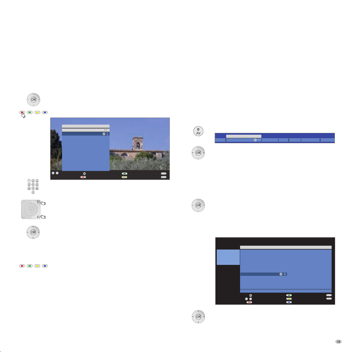
Call index
➠ In normal TV mode, without other displays.
Index.
Call
You will see an info text for the highlighted keyword in
the info display.
If an OK symbol appears in the marked line, this function
can be called directly with
Language, Integrated features
OK.
Permanently display or hide the automatic info display
Once you have become familiar with how to operate the TV set, you can
switch off the automatic info display.
➠ In normal TV mode, without other displays.
Call TV menu.
34 Select Settings,
6go to the menu line below.
34 Select Miscellaneous,
6go to the menu line below.
34 Select On-screen displays,
6go to the menu line below.
- 14
34 Select Automatic info,
6go to the menu line below: yes / no.
Selecting a keyword
Enter initial letters with the
numeric buttons like with a
mobile phone keypad (see page 13).
or go with:
34to the preceding / next letters,
6from line to line,
P+/P– scroll backwards or forwards in whole pages.
Example: You want to have the TV set switch off automatically at
a specific time:
Select the keyword
Switch off → Automatic, with OK you
will go to the setting.
Page 15
Operating convenience
Settings
Station
Parental lock
Timer functions
TV menu
Picture Sound
Connections
Language
Miscellaneous
On-screen displays
Time and date
Radio menu
Sound
Station
Timer functions
Recording
Recording wizard
(1
Timer list
Pre-record time
Post record time
New devices/modifications
(1
Sound components
(1
Antenna DVB
(1
Digital Link Plus
Miscellaneous
Manual adjustment of AV standard
Assign digital audio input
Allow switching voltage
RGB insertion at AV2
Switch off times
Alarm times
Wake up with
Wake up signal volume
Time
Deviation from Universal Time
Date
Beginning of daylight-saving time
End of daylight-saving time
Software update
(1
DVB subtitles
Auto volume
AV output signal
Maximum volume
Switch on volume
Volume adjustment for
current station
Picture adjustment
Contrast
Colour intensity
Colour temperature
Brightness
Sharpness
Digital Noise Control (DNC)
more...
On-screen display time
On-screen display position
Volume
Automatic info
Search wizard
(1
Manual adjustment
Change stations
Search wizard
(1
Manual adjustment
Change stations
Select/change favourites
Image+
Picture format
Move picture up/down
Auto format
Film quality improvement (DMM)
Sound mode
DPLII mode
(2
Sound adjustment
Headphone volume
Loudness
more...
Sound mode
DPLII mode
(2
Sound adjustment
Headphone volume
Loudness
more...
DVB character set
Activate switch-off position
Set switch-off position
Basic adjustment
Western European
Polish
Standard
Loudspeaker sound
(3
Headphone sound
(3
Auto volume
AV output signal
Maximum volume
Switch on volume
Volume adjustment for
current station
Switch off times
Alarm times
Wake up with
Wake up signal volume
Rotate TV
(4
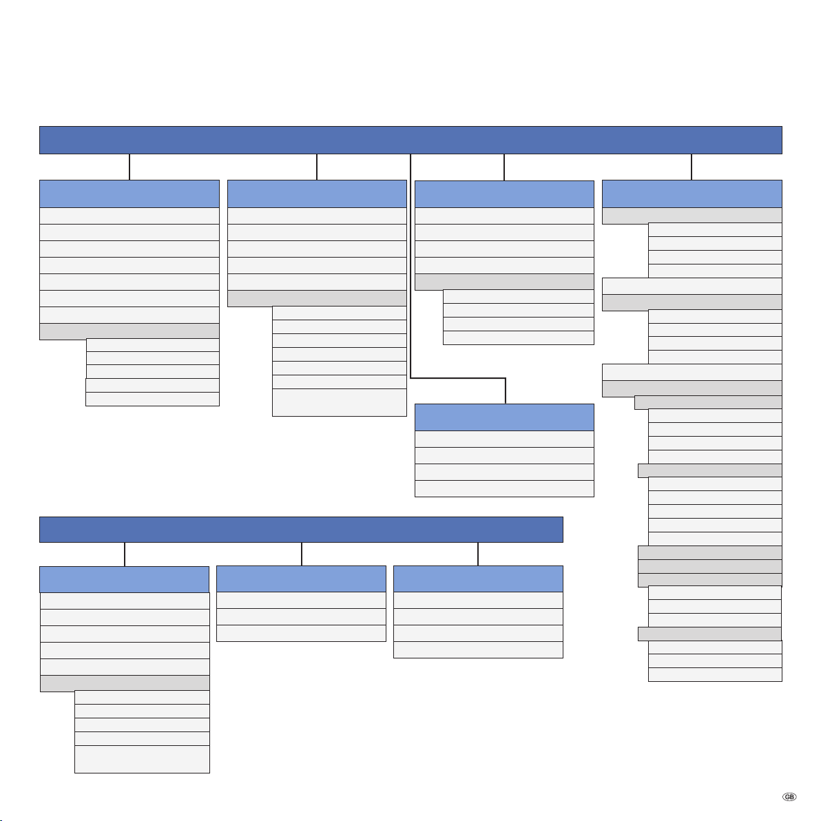
TV menu – Overview diagram
Radio menu – Overview diagram
(1
A wizard is started here.
(2
Menu item only appears when more than 2 speakers are selected in the listening mode.
(3
Menu items only appear for analogue stations.
(4
Menu item only appears when, for example, a stand with motor drive (see Accessories,
Installation possibilities, page 55) is used.
15 -
Page 16
END
INFO
0 9
-
OK
OK
P+
P–
Station list
21:00 - 21:45 Urlaubsparadies - Toskana
Scan stations
Change stations
Change sorting
COMP. IN
HDMI1/DVI
HDMI2/DVI
VGA
AVS
DVD
VCR
0 VIDEO
1 Das Erste
2 ZDF
3 WDR Köln
4 Bayrisches FS
Switch to ...
Select station
Favourites
5 hr-fernsehen
6 Phoenix
7 BR-alpha
8 3sat
9 EinsExtra
10 EinsFestival
11 EinsPlus
12 ZDFinfokanal
13 ZDFdokukanal
14 ZDFtheaterkan
15 arte
16 DAS VIERTE
Page ↑↓
END
INFO
OK
OK
P+
P–
a
z
-
Station list
21:00 - 21:45 Urlaubsparadies - Toskana
Scan stations
Change stations
Change sorting
3sat
9Live
arte
ARD
AVS
Bayrisches FS
BR-alpha
BR
CNN INT
Switch to ...
Select letter
Favourites
COMP IN
Das Erste
DSF
DVD
DVD-REC
EinsExtra
EinsFestival
EinsPlus
Eurosport
Page ↑↓
Daily operation
Select station
With the keys P+ and P– on the remote control
P+/P– station up/down.
The station display with sound identification is displayed
briefly.
➠ If favourites are selected, the station is switched over
in the favourites list with
➠ The symbols for the sound identification are described
on page 21.
➠ If there are additional languages or DVB subtitles for
DVB stations, then language and subtitle selection is
shown below the station display.
See also page 21: Additional selection possibilities for
DVB stations.
With the numeric keys of the remote control
1-digit stations
long
Keep the
the station changes immediately.
numeric button pressed for one second,
or:
Press the
numeric button briefly, the station changes
after 2 seconds (changes immediately in case up to 9
stations are stored).
2-digit and 3-digit stations
Press first (and second)
short short long
Keep the last
numeric button pressed for one second,
the station changes immediately.
or:
Press all the
numeric buttons briefly, the station
changes after 2 seconds (changes ilmmediately up to
99 or 999 stored stations).
P+/P– (see page 17).
numeric button briefly.
With the station list
➠ In normal TV operation, without further displays, no
favourites selected:
OK call Station list.
Sorting
numerically
P+/P– scroll in the pages of the station list.
634 Mark stations.
or:
Enter the number of the station with the
The marked station is shown as a small picture.
OK the marked station is called.
Blue button: Changes sorting from numeric to alphabetic.
Sorting
alphabetically
numeric buttons.
4-digit stations
Press all four
all short
- 16
immediately.
➠ If favourites are selected, the station in the favourites
list is switched to with the numeric buttons (see page
17). A maximum two-digit station input is possible.
➠ If you select an unoccupied station slot, the next available station is switched to.
numeric buttons, the station changes
Enter initial letters with the
like with a mobile phone keypad (see page 13).
numeric buttons
The first station for the specified letters is marked.
634Mark stations.
OK the marked station is called.
Page 17
Daily operation
END
INFO
OK
OK
P+
P–
Switch to ...
Station list
Favourites 1
Favourites
1 Das Erste
2 ZDF
3 WDR Köln
4 Bayrisches FS
5 hr-fernsehen
6 Phoenix
7 BR-alpha
8 3sat
9 EinsPlus
10 EinsExtra
11 MTV
12 VIVA
Select station
Page ↑↓
Scan stations
Change favourites
0 9
-
OK
DVD-REC
DVD
AV selection
AVS
PC IN
HDMI1/DVI HDMI2/DVIVIDEO
END
INFO
0 9
-
OK
OK
P+
P–
Station list
Scan stations
Change stations
Change sorting
COMP. IN
HDMI1/DVI
HDMI2/DVI
VGA
AVS
DVD
VCR
0 VIDEO
1 Das Erste
2 ZDF
3 WDR Köln
4 Bayrisches FS
Switch to ...
Select station
Favourites
5 hr-fernsehen
6 Phoenix
7 BR-alpha
8 3sat
9 EinsExtra
10 EinsFestival
11 EinsPlus
12 ZDFinfokanal
13 ZDFdokukanal
14 ZDFtheaterkan
15 arte
16 DAS VIERTE
Page ↑↓
With the favourites lists
You can save and call your favourite stations in 6 favourites lists (e.g. for
multiple users). Each favourites list can contain up to 99 stations. After
initial installation, 10 stations from the station list are already stored in
the first list. Change the favourites list to suit your requirements (see
together – changing favourites lists on page 24).
➠ In normal TV mode, without other displays:
OK calls the station list
.
Red button: calls the favourites list.
Select station directly with
numeric buttons.
Or:
P+/P– scroll in the pages of the favourites list.
6 Mark stations.
OK the marked station is called.
34 Select other favourites list
➠ Other favourites lists can only be selected if they also
contain stations.
Red button: Back to the station list.
Green button: Scan all stations of the currently selected
favourites list
.
Yellow button: Change the favourites lists, see page 24.
Explanation of the favourites lists
The selection made with the red button (station list or favourites list) is
retained until the next call. All inputs then refer exclusively to the currently
selected favourites list.
If favourites are selected, the name of the favourites list appears after
the station name.
Put
Explanation of the icons following station names:
Digital DVB-T station (terrestrial via antenna)
Digital DVB-C station (via cable)
Digital DVB-S station (via satellite)
Coded station
Select video source
➠ Please ensure that the appropriate devices have also been registered
with the device connection wizard (see page 35).
Via AV selection
Call AV selection.
34 Select desired device or connection,
OK to switch over.
A signal from the selected video source should now be
visible.
Via station list
➠ In normal TV mode, without other displays:
OK call the station list
In numerical sorting the connections or devices are always
at the beginning of the list.
In alphabetic sorting, the connections or devices are
sorted in alphabetically.
6
34Select connection/device.
OK to switch over.
.
17 -
Page 18
Daily operation
END
Sound adjustmentVolume
Sound mode DPLII mode
24
Headphone volume
4
Sound mode ...
(5)
optimal
3 2 1
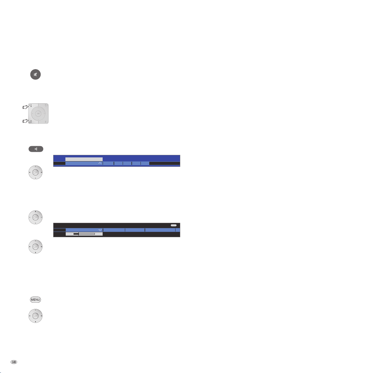
Adjusting the sound
Switching sound off/on
Sound off;
Sound on: Press button again or set volume
Setting the volume
V+/V– volume louder / quieter.
The volume bar will be shown briefly if no other menu
is displayed.
Setting the sound mode
Sound mode.
Call
34 Select the number of speakers you want to hear.
Additional sound settings for volume adjustment and for Sound mode:
➠ As long as you can still see the volume bar or the
selection of speakers for sound mode
Call additional sound settings.
34 Select sound setting,
6 Go to the menu line below.
34 Make changes.
Sound settings via the TV menu
➠ In normal TV mode, without other displays.
Call
TV menu.
34 Select Sound,
6go to the menu line below.
34 Select desired sound setting,
6 Go to the menu line below.
34 Make changes.
- 18
Explanations of the sound settings:
Sound mode
Select the number of speakers you want to hear. The
selection depends on the connected sound components
(from page 39) and on the transmitted audio signal.
V+.
➠ If the number of speakers appears in brackets, the
sound of missing speakers is transmitted by the existing
speakers (virtual).
optimal
The momentarily reproduced audio signal is output with
the ideal number of speakers.
1
Play centre sound or mono (left/right).
2
Play front sound (L/R stereo).
3
Play front and centre sound.
4
Play front and surround sound.
5
Play front, surround and centre sound.
➠ You can also enter the number of speakers with the
numeric buttons of the remote control.
Amplifier
play via an external HiFi amplifier. Selection is only
possible if an amplifier has been selected in the sound
components wizard.
Sound
adjustment
Headphone vol.
Loudness
:
DPLII mode
Speech, Classical, Pop, Custom music, and Custom film
sound.
Adjust the headphones volume.
Proper boost of bass and treble tones at low volume.
Here you can make Dolby Pro Logic II sound settings for
movie, music, matrix and personal settings. Menu item
only appears when more than 2 speakers are selected in
the sound mode.
more ...
Speakers/
Headphones
Auto Volume
call with
Sound
Selection possibility Mono/Stereo or Sound 1 or Sound
OK.
2 for two-sound broadcasts separately for speakers and
headphones. Only available for analogue stations.
Reduces volume differences, e.g. for advertisements that
are too loud.
AV output
Sound selection for two-sound broadcasts.
signal
Maximum
Determining the maximum volume that can be set.
volume
Switch on
volume
Specify the volume that is set when switching on the TV
set with the mains switch. This does not affect switching
the set on from standby mode.
Volume
adjustment for
current station
The volume can differ according to the individual stations.
If the sound is too loud or too quiet in relation to other
stations, adjust the volume. When the menu is open, you
can select the stations one after another with
P+/P– and
adjust every single station conveniently.
Page 19

Daily operation
Brightness
Volume
Direct control on TV set
19
Contrast Picture format StationAV selection
END
INFO
Sound
Connections
Recording SettingsPicture
TV menu
Picture adjustment ...
Picture
Here you can adjust among other things: Contrast, colour, brightness, picture
adjustment, sharpness, picture format.
END
INFO
Contrast
Colour temperature
Colour intensity
Picture adjustment
Picture (standard values, TV digital)
TV menu
Picture adjustment
Here, you can switch between the preset standard values for contrast, colour
intensity, colour temperature, brightness, focus and digital noise reduction
and your own personal values. Each of the signal input groups „TV analogue“,
„TV digital“, „HD analogue“, „HD digital“, „PC“ and „PhotoViewer“ has its own
values. Refer to printed operating manual.
Standard values (TV digital) ...
END
INFO
OK
Picture adjustment
Picture (personal values, TV digital)
TV menu
Standard values (TV digital)
Personal values (TV digital)
Adjusting the picture
Call TV menu.
34 Select desired values for picture,
OK call selected values for picture.
34 Select Picture,
6go to the menu line below.
34Select the desired picture function,
6 go to the menu line below.
34 Make changes.
Explanations of the picture settings
Picture
adjustment
Contrast
Colour intensity
Switches the picture parameters between standard and
personal values.
Adjust contrast.
Adjust the colour.
Set warmer or cooler tints for the picture.
Colour
temperature
Brightness
Sharpness
more ...
Image+
Picture format
Vertical
Adjust the brightness of the picture.
Adjust the contour sharpness of the picture.
Removes or reduces the signal noise in the picture.
DNC
Call with
OK.
Image improvement on/off and demo mode.
Setting possibilities for the picture format (see page 20).
Move picture vertically (see page 20).
picture hold
Auto format
With Auto format switched on, the TV set recognises the
picture format for
Cinemascope or wide screen movies
and adapts accordingly
Reduce image jolting
DMM
Standard values / personal values for picture adjustment
Call
TV menu.
.
34 Select Picture,
6go to the menu line below.
34 Select Picture adjustment,
6 go to the menu line below.
Explanations for picture adjustment
Custom adjustments of
contrast, colour intensity, colour temperature,
brightness, sharpness and digital noise supression are saved in the personal values. There are separate personal values for every signal source
(TV analog, TV digital, HD analog, HD digital, PC, PhotoViewer).
By selecting
Standard values the picture parameters are reset to factory
values for the respective currently active signal source.
For an explanation of the signal source; see glossary:
Signal input
groups.
In the index of the TV set, all the picture and sound adjustments can be
reset to the factory values for all signal sources in one step under
Reset pic-
ture/sound or Initialise picture/sound or Factory settings picture/sound.
Operation without remote control
Changing the station on the TV set
+ / – Station up/down.
Switching radio on or off or switching to radio
R Radio on / off or switching between TV and radio.
Calling the TV menu on the set
.
➠ Service is for customer service personnel only.
call Direct control on TV set menu,
M
– / + select function.
M or R go to the menu line below,
– / + make changes.
M move up one menu line,
– / + select other function.
19 -
Page 20

Daily operation
Detailed info (teletext) Programme previewDetailed info
Programme info 14:43
1 ARD
14:30 - 15.15 Urlaubsparadies Toskana
END
OK
END
INFO
OK
with double size
with normal size
Teletext subtitles
14:42
OK
END
INFO
PhotoViewer IndexRadio
DR archive
ASSIST+
Activate
OK
Favourites Personal text pages
Button functions
Each operating mode of the TV set (TV, Radio, Teletext, EPG, or Picture
in Picture) has a separate menu and separate functions for the coloured
buttons. The assignment of the coloured buttons is illustrated in the
description of the individual operating modes.
Below, some of the button functions are listed which you need for daily
operation of your TV set.
Functions of the coloured buttons in TV mode
Red button: Digital Recorder: DR archive on/off.
Green button: Call menu Teletext subtitles.
34 Select size of the Teletext subtitles,
OK show Teletext subtitles.
(display only if subtitles are available).
END: Teletext subtitles off.
Yellow button: Go to the last viewed station.
Use this button to quickly switch back and forth
between two stations.
Blue button: Show programme info.
The
Panorama picture format can be switched between
proportionally correct and format filling reproduction.
Dark margins are visible on the right and left of the picture
in proportionally correct reproduction.
Switching over: Keep the
at the same time press the
M button on the set pressed,
Picture format button on the
remote control briefly.
Resetting: Press the same button combination again.
Explanations of the picture formats
➠ Setting possibilities depend on the displayed picture
content.
16:9 Proportionally correct display of 16:9 programmes.
4:3 Proportionally correct display of 4:3 programmes.
Panorama Proportionally correct or format filling reproduction of 4:3
broadcasts on the 16:9 screen. Station logos and subtitles
remain intact. See above for switching Panorama mode.
Cinema Proportionally correct, format filling display of 4:3 broad-
casts on 16:9 screens.
Zoom Proportionally correct display. Maximum picture magni-
fication.
PALplus Is a 4:3-compatible 16:9 picture broadcast supplied by
the station which is detected automatically.
If a high-resolution picture signal is displayed on the TV
set or fed in via the interfaces PC IN, HDMI1/DVI, HDMI2/
DVI or COMP. IN, the picture formats 16:9 TV, 4:3 TV as
well as 16:9 PC, 4:3 PC and
Zoom can be set.
Permanent display of time
Selecting the picture format
- 20
Press twice in rapid succession,
the time is permanently displayed.
K or END: Hide time.
Press the picture format button until the desired picture
format is marked or
34 to select the desired picture format.
Move picture vertically
➠ In normal TV mode, without other displays:
6Move picture up/down.
To show subtitles or news tickers which have been cut
off, the picture can be moved up or down in the picture
formats
resolution signal) with the
Call Assist+
Call the
34Select DR archive, Radio, Favourites, PhotoViewer,
Index, Personal text pages.
OK calls the function.
Panorama, Cinema and Zoom (not with high
arrow buttons 6.
Assist+ menu.
Page 21

14:42 Alarm time 20:00 Sleep timer 23:00
1 Das Erste Digital (5)
14:30 - 15:15 Toskana
Language-/sound selection
Daily operation
Status display
➠ In normal TV mode, without other displays:
END: Show / hide status display.
In the top two lines you will see the number and name of
the station, the title of the programme currently running
(if available) and the sound identification.
The time and, if activated, the alarm time and switch-off
time are displayed at the bottom.
Explanations of the symbols for sound identification:
Transmitted audio signal:
Mono Mono audio transmission analogue
2-sound Two-sound transmission (Sound1/Sound2) analogue
Stereo Stereo sound transmission analogue or digital (PCM)
Digital Dolby Digital sound transmission (DD)
dts dts sound transmission
MPEG MPEG sound transmission
ProLogicII Dolby Pro Logic II
Transmitted audio channels:
DD / dts 1.0 / mono
DD / dts / MPEG 2.0
DD / dts
DD / dts
DD / dts
DD / dts
DD / dts
DD / dts
DD / dts
Selected listening mode:
1 Play centre sound or mono (left/right).
2 Play front sound (L/R stereo).
3 Play front and centre sound.
4 Play front and surround sound.
5 Play front, surround and centre sound.
➠ If the number of speakers appears in brackets, the
sound of missing speakers is transmitted by the existing
speakers (virtual).
Additional selection possibilities for DVB stations
In the status display additional selection possibilities can be offered for
specific programmes depending on the DVB programme provider.
➠ If during the status display you press one of the
coloured buttons or the TEXT button then the associated
selection menu will be displayed.
The following options are possible:
Red button:
Channel selection for multi-channel providers
Green button: Language/audio selection
Yellow button: Time selection
Blue button: Protection of minors
TEXT: DVB subtitles
The selection menus are only available as long as the
status display is shown. However you can call them again
by pressing the
END button.
Explanations of the selection possibilities
DVB subtitles
The subtitle selection refers exclusively to DVB subtitles
and is not offered by all stations. Many stations only
transmit subtitles by teletext.
You can make general settings for DVB subtitles under
TV
menu → Settings → Miscellaneous → DVB subtitles.
New
programme
The selection line is automatically displayed briefly, if a
new programme begins with options that are different
from those of the previous programme, or if you switch
to a different station.
21 -
Page 22

Managing stations
Start search/updateChange search settings
Search wizard
TV menu
Settings
Stations
Search wizard
Your TV carries out the update of the station range (search for new stations;
delete stations no longer broadcast) with the following settings:
Location of TV set Germany
Signal source Antenna/cable (analogue)
TV/colour standard PAL-BG
END
OK
Proceed
Search wizard
Automatic TV station search and sorting finished.
Search for/update station
New found stations
30 TELE 5
31 N 24
32 QVC
33 E26
OK
OK
TV stations
Various options for managing stations are available via the TV menu. For
example the description for TV stations. For radio stations the same applies,
except that the radio menu is called in radio mode (see also page 34).
➠ Station management is not possible if a programmed timer recording is still pending.
Search/update stations – Search wizard
In the search/update with the search wizard, new stations are searched
for which are not yet stored.
➠ You have to repeat the initial installation (see page 11)
and automatically search for new ones if you want to
delete all the existing stations and automatically search
for new ones.
Call
TV menu.
34 Select Settings,
6go to the menu line below.
34 Select Stations,
6go to the menu line below.
34 Select Search wizard,
6go to the menu line below.
In the upper info text the current search settings will now
be displayed:
Explanations of some search settings:
Set location
Select the country for country-specific defaults and
station sorting.
Signal source
Select antenna, cable, or satellite here, depending on
where you want to search for new stations.
At this point you can also call a configuration of the
DVB-T and DVB-S antennae via the yellow button (see
page 12).
Antenna/cable:
TV/colour
standard
With selection of set location the conventional TV
standard/colour standard is the default. This should only
be changed if stations with other standards are to be
searched.
DVB-T
Search method
If you want to run the station search independently of
the channel grid, select
method.
DVB-C
Settings
With the selection of set location the conventional set
tings will be preset. Only change this if you know other
symbol rates and modulation types or if you have to
specify the network ID for your cable network (informa
tion available from your cable network provider).
If you want to run the station search independently of
the channel grid, select
method.
DVB-S
Symbol rate
The symbol rate is specified by the satellite provider and
normally does not need to be changed.
Search/update stations – Search ended
After the station search has ended, the number of new
found stations is displayed.
OK to continue.
If new stations are found, these are displayed with the
appropriate station number.
frequency search for the search
-
-
frequency search for the search
If you want to change these search settings:
- 22
34 Select Change search settings,
OKwizard prompts search settings.
If you agree with these settings:
34 Select Start search/update,
OKstart search.
Red button: Abort current search/update.
OK to continue.
END: to exit search wizard.
Page 23

Managing stations
END
INFO
Manual adjustment
Signal source Antenna/cable (analogue) DVB-T DVB-C D
Channel S21
Frequency 303.25 MHz
Name KIKA
TV stand. B/G
Col. standard Autom.
Store
Search
Signal source
Select the area in which you want the broadcaster to search here. You can
use the button to automatically select station by station.
END
INFO
0 9
-
P+
P–
Change stations
Restore stations
Move
Rename
1 ARD
2 ZDF
3 SAT.1
4 D Vierte
5 RTL
6 VOX
7 S-RTL
8 N-TV
9 DSF
10 EinsPlus
11 9Live
12 RTL2
Select station
Delete
13 WDR 3
14 BR
15 HR
16 MDR 3
17 KIKA
18 PHOENIX
19 BR-ALPHA
20 3SAT
21 KABEL 1
100 Das Erste
101 ZDF
102 WDR Köln
Page ↑↓
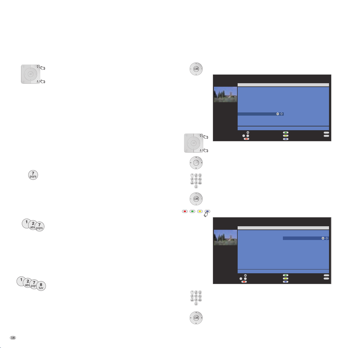
Change stations
Here you can move station, delete stations, restore stations you have
deleted and enter and change station names of analogue stations.
Search/update station – manual search
Call
TV menu.
34 Select Settings,
6go to the menu line below.
34 Select Stations,
6go to the menu line below.
34 Select Manual adjustment,
OKcall input box.
You can enter or edit the station data in the following
lines:
Or:
Blue button: Starts Search and searches for next station.
Red button: Stores station.
➠ Only stations for the selected signal source can be
saved which do not yet exist in the station list.
➠ Stations which already exist in the station list for the
selected signal source are displayed with their station
numbers and names on a grey background. These stations
can only be overwritten with the
red button.
Change, delete, move, rename, restore stations
➠ Change stations can also be called via the station list
(page 16).
TV menu.
Call
34 Select Settings,
6go to the menu line below.
34 Select Stations,
6go to the menu line below.
34 Select Change stations,
OKcall list of stations.
In this menu you can
delete, move, rename or restore
stations.
346or
numeric buttons:
to select the appropriate station.
Scroll with
P+/P– if necessary.
Explanations of some search settings:
Various settings are possible depending on the selected signal source.
Some settings have already been explained in the initial installation (see
page 12 onwards).
Signal source
Selection of range in which you want to search for the
station.
Channel
Frequency
TV stand.
Col. standard
Direct input of channel.
Direct input of station frequency.
Input of station TV standard.
(B/G, I, L, D/K, M, N) Ask your dealer in this regard.
Input of the station colour standard.
(PAL, SECAM, NTSC-V, PAL60, Autom.)
Ask your dealer in this regard.
Delete station
Red button: Activates Delete station.
6 mark several stations if needed,
OK to execute the delete.
Move station / Change order
➠ Stations can only be resorted within their signal
source block.
Yellow button: Activates Move station.
6 mark several stations if needed,
OK to end marking.
6Selection insert position from which the marked
stations are to be inserted,
OK to execute the move.
23 -
Page 24

Managing stations
END
INFO
OK
P+
P–
0 9
-
All stations
Select/change favourites
1 Das Erste
2 ZDF
3 WDR Köln
4 Bayrisches FS
5 hr-fernsehen
6 Phoenix
7 BR-alpha
8 3sat
9 EinsExtra
10 EinsFestival
11 SAT.1
12 RTL
Stations of Favourites 1
1 Das Erste
2 ZDF
3 WDR Köln
4 Bayrisches FS
5 hr-fernsehen
6 Phoenix
7 BR-alpha
8 3sat
9 EinsExtra
10 EinsFestival
11 SAT.1
12 RTL
Select station Next favourite list
Clear favourite list Change sorting
Page ↑↓
END
INFO
P+
P–
OK
OK
Change stations
Restore stations
3sat
KIKA
ZDF
ZDFinfokanal
ZDFdokukanal
ZDFinfokanal
Eurosport
NONAME
RTL
Phoenix
BRalpha
NDR FS HH
Das Erste
Das Vierte
RTL Television
9Live
WDR Köln
VOX
ProSieben
Super RTL
n-tv
DSF
RTL2
KABEL1
Page ↑↓
Restore
Cancel restore
Rename station
➠ DVB stations for which the station name is also broadcast cannot be renamed. In this case, the
Rename function
is hidden.
Blue button: Activates Rename station.
Under the 1st letter of the name you will see a line indi
cating the current input position.
4Input position right (also for spaces).
3Input position left deletes the preceding character.
Enter the letters one after another with the numeric
buttons on the remote control. Like using a mobile phone
keypad, press a numeric button until the desired charac
ter appears. The available letters are printed respectively
on the buttons. Different special characters can be
selected with button 1.
Green button: Switch upper/lower case letters.
OK to save new name.
Restore stations
Stations which have been deleted from the station list can be restored.
➠ The restore list is empty if no stations have been
deleted yet.
Green button: Activates Restore stations.
Put together – change favourites lists
Each favourites list can contain up to 99 stations. You can put together
the favourites lists to suit your requirements (e.g. topic lists). Other persons
using this TV set can create their own favourites lists.
The favourites lists also have the advantage that the stations of different
signal sources can be stored in the order you wish.
➠ Change favourites lists can also be called via the
favourites list (page 17).
Call
TV menu.
34 Select Settings,
-
6go to the menu line below.
34 Select Stations,
6go to the menu line below.
34 Mark Select/change favourites,
OKcalls list of all stations and last active favourites list.
- 24
634Select station,
OK
The restored station is sorted in according to its signal
source at the end of the respective signal block
station is restored.
Green button: Select the next favourites list.
Rename favourites list
➠ Favourites list (right column) must be selected.
If not, change the list with
4.
Blue button: Activates Rename favourites list.
Numeric buttons: Enter new name (same procedure as
for rename station, see left column).
OK to save new name.
.
Page 25

Managing stations
END
INFO
OK
OK
P+
P–
0 9
-
All stations
Select/change favourites
21 EinsPlus
22 ZDFinfokanal
23 ZDFdokukanal
24 ZDFtheaterkan
25 MDR FERNSEH
26 rbb Berlin
27 rbb Brandenburg
28 arte
29 KiKa
30 NDR FS HH
31 NDR FS MV
32 NDR FS NDS
Stations of Favourites 1
13 BR-alpha
14 3sat
15 EinsExtra
16 EinsFestival
17 SAT.1
18 RTL
19 arte
Adopt to favourite list
Select station Next favourite list
Clear favourite lsit Change sorting
Page ↑↓
END
INFO
OK
OK
P+
P–
All stations
Select/change favourites
21 EinsPlus
22 ZDFinfokanal
23 ZDFdokukanal
24 ZDFtheaterkan
25 MDR FERNSEH
26 rbb Berlin
27 rbb Brandenburg
28 arte
29 KiKa
30 NDR FS HH
31 NDR FS MV
32 NDR FS NDS
Stations of Favourites 1
1 Das Erste
2 ZDF
3 WDR Köln
4 Bayrisches FS
5 arte
6 Phoenix
7 BR-alpha
8 3sat
9 EinsExtra
10 EinsFestival
11 SAT.1
12 RTL
Select insert position Select station
Execute move Cancel move
Page ↑↓
0 9
-
Add station to favourites list
3Go to the left column (all stations).
P+/P– Scroll in the pages of the station list if necessary.
6Mark station or select station with the numeric
buttons (
initial letter
favourite to the favourites list.
OK transfers the station to the favourites list.
The new station is inserted at the end of the
favourites list
for alphabetical station sorting enter the
) which is to be transferred as a
.
Move / change order of stations in the favourites list
➠ Favourites list (right column) must be selected.
If not, change the list with
6
mark station to be moved.
4.
Yellow button: Activates Move station.
6Select insertion position at which the marked
station is to be inserted.
The insertion position can also be selected with
the numeric buttons.
OK to execute the move.
Proceed in the same manner with additional stations.
Delete station from favourites list
➠ Favourites list (right column) must be selected.
If not, change the list with
6mark station to be deleted.
OK removes the marked station from the favourites list
or:
Red button: Activates Clear favourite list.
OK confirms clear list.
4.
.
25 -
Page 26

Picture in Picture
2 ZDF
17.00 - 18.30 Flora & Fauna
1 ARD
17.30 - 20.00 Toskana
Picture in Picture (PIP)
The concurrent display of two different images is referred to as Picture
in Picture.
➠
A concurrent representation of two HDTV signals is not possible.
➠
A concurrent representation of two coded stations is not possible.
➠
Picture change and station selection is restricted during recording.
Your TV set differentiates two PIP types:
Split Screen In this case the screen is divided in the middle and the
Small PIP In this case a small PIP image is inserted in the TV pic-
Start and end Picture in Picture mode
PIP as freeze picture
additonal PIP image is shown on the right side of the
screen. Both images are compressed horizontally and
each gets half of the screen.
ture.
Show/hide PIP.
A green frame indicates that the station selection affects
the PIP, A white frame means that the operation affects
the main picture.
➠ The frame is green,
if not, press the
green button.
Red button: Freeze picture in PIP on / off.
Select the PIP picture
➠ The frame is green,
if not, press the
green button.
Select the station as usual.
Select the station for the main picture
➠ The frame is white,
if not, press the
green button.
Select the station as usual.
Swap contents of PIP and main picture
➠ The frame is green,
if not, press the
green button.
Yellow button: Swaps contents.
- 26
Scan station in the PIP
➠ The frame is green,
if not, press the
Blue button: Start / stop Scan station.
The frame turns blue,
the stations now change automatically.
green button.
Page 27

Picture in Picture
END
INFO
Split screen
Type
TV menu
Settings
PIP
Small PIP
END
INFO
Split screen
Type
TV menu
Settings
PIP
Small PIP
END
INFO
Split screen
Type
TV menu
Settings
PIP
Small PIP
Configure Picture in Picture (PIP) mode
In the PIP menu, you can set the PIP type (split screen or small PIP) and
the position of the small picture.
Start PIP menu
➠ PIP mode started,
if not, press
➠ The frame is green,
if not, press the
Call the PIP menu.
Switch over to small picture
➠ PIP menu open.
PIP button.
green button.
Change position of the PIP
➠ Other than the status line, which may possibly be
displayed, no other display is shown on the screen:
634Move the PIP into a corner of the screen.
Moving the small picture is possible if there is a green,
white and blue frame.
The position of the small picture can also be selected
under
Position in the PIP menu.
Switch to Split Screen
➠ PIP menu open.
34 Select Type,
6go to the menu line below.
34 Select Type,
6go to the menu line below.
34 Select Split Screen.
34 Select Small PIP.
27 -
Page 28

Electronic Programme Guide
END
MENU
P+
P–
TEXT
OK
0 9
-
OK
15:57-16:59 arte Charmed - Zauberhafte Hexen
16:00-16:15 MDR FERN... Hier ab vier
16:00-16:10 EinsExtra EinsExtra Aktuell
16:00-17:15 SAT.1 Richter Hold
16:00-16:30 ProSieben M. Asam - Mode
16:00-16:55 ZDFtheater... Waschtag
16:05-17:00 Bayrische... Wir in Bayern
16:05-16:45 KiKa Skippy, der Buschpilot
16:05-17:00 KABEL1 Star Trek - Das nächste Jah...
2 ZDF
EPG (Electronic Programme Guide) Mon 31.07./16:05
Detail View Record
Page ↑↓ Select time Select date, ... , topics
Date
Time
Station
Topics
Mon 31.07
now
all
all
soon 17:00 18:00 19:00
Charmed - Zauberhafte Hexen
20:00
END
MENU
15:57-16:59 arte Charmed - Zauberhafte Hexen
16:00-16:15 MDR FERN... Hier ab vier
16:00-16:10 EinsExtra EinsExtra Aktuell
16:00-17:15 SAT.1 Richter Hold
16:00-16:30 ProSieben M. Asam - Mode
16:00-16:55 ZDFtheater... Waschtag
16:05-17:00 Bayrische... Wir in Bayern
16:05-16:45 KiKa Skippy, der Buschpilot
16:05-17:00 KABEL1 Star Trek - Das nächste Jah...
2 ZDF
EPG (Electronic Programme Guide) Mon 31.07./16.05
Change to programme list
Date
Time
Station
Topics
Mon 31.07
now
all
all
Tue 01.08. Wed 02.08. Thu 03.08. Fri
Charmed - Zauberhafte Hexen
Electronic Programme Guide – EPG
EPG stands for Electronic Programme Guide and provides you with
on-screen programme details. With the system, as with a printed pro
gramme guide, you can learn about the current programme. In addition
programmes can be sorted according to certain topics, memorised, and
also recordings can be programmed.
Starting and ending EPG
Switching EPG on / off
The first time you start EPG a wizard becomes active
(not for DVB), and it guides you through the setup. Then
execute the data capture (see next page).
The display of the programme guide is divided into two
branches. The lower programme list is influenced by the
upper default lines.
Blue button: Switches between the upper default lines
date, ..., topics and the lower programme list.
Switching and memorizing with the programme list
➠ In the program list first all currently running programmes
are listed.
➠ You are in the lower programme list,
if not, press the
6 Select station,
View The programme is in progress the TV set switches to the
Memorise The programme has not started yet and is memorised. A
- 28
OK view / memorise.
marked programme.
appears in front of the programme. The TV set switch
es over automatically to the beginning of the programme
or, if set in the menu (page 29) on from standby mode.
blue button.
Adjusting the programme list
➠ Selection is at the top in the defaults,
-
if not, press the
blue button.
6Select Date, Time, Station or Topics.
34Select defaults within the respective line.
Example If you are looking for the next news broadcast, select
today's date, for time, select
and for topics, select
News. Then you get a list of all news
soon, for station select all,
programmes in the programme list below.
Time entry If the line
Time is selected, then you can enter the time
after which the programmes will be displayed via the
numeric buttons of the remote control. Always enter
four digits, e.g. 0900 for 9.00 in the morning.
Favourites If a favourites list has been selected in the Station line,
only the programmes of stations in the favourites list are
displayed in the programme list.
Tip Before pressing the blue button to leave the upper selec-
tion lines, select one of the preceding lines. If you then
switch back to the programme list, you can change this
menu line with
gramme list. If you have marked
34, without having to leave the pro-
Time, then you can enter
the time, after which the programmes will be displayed,
with the numeric buttons of the remote control.
Paging through the programme list
P+/P– paging backwards / forwards.
In the entries for
Date and Time, you will see changes in
time as well as in date when paging.
-
Page 29

Electronic Programme Guide
END
INFO
OK
EPG menu
Data capture
Switch on TV when marked
Calling additional information about the programmes
➠ Brief information about many programmes is displayed
below the programme list of the broadcasts.
You can call detailed information with the
this function is offered by the TEXT icon in the lower
left.
Programming a recording for a recorder
➠ Selection is in the lower programme list,
if not, press the
6 Mark the desired programme.
Red button: Starts recording wizard.
Change or confirm timer data if necessary (see page 46,
the direct recording path).
Then a
red dot will be displayed in front of this programme
as an identification.
Red button: Deletes the already programmed recording
of the red marked programme from the timer.
If the timer data have been transferred to an external
recorder, then the timer must also be deleted there.
Configuring EPG
Start the EPG menu
➠ EPG mode is started,
if not, press the
Call the
Settings in the EPG menu:
Select provider, Station selection, Data capture, Switch on
TV when marked.
blue button.
EPG button.
EPG menu.
TEXT button if
Station
selection
Data capture
Switch on TV
when marked
You can remove certain stations from the programme
guide. These stations must be deactivated in the
Station
selection. First, all stations for which programme infor-
mation can be provided are marked with a
. Stations
without a are not included in the programme guide.
Marking the stations according to reception ranges:
analogue stations via antenna/cable, for which the
current provider supplies data.
digital terrestrial stations DVB-T,
digital cable stations DVB-C,
digitale satellite stations DVB-S.
If you want to use EPG for analogue and digital stations,
select
on (for DVB + analogue). If you want to use EPG
and only have DVB reception, select
on (only for DVB).
If you are not using EPG and therefore do not want to
receive any EPG data, select
off.
After making changes in the EPG menu, or each time the
mains switch has been switched off, the EPG data must
first be captured. To do this, switch on the device and
select (for analogue stations) the station that you have
defined as provider, and let the TV set run for about 1
hour with the selected station. Or switch the TV set to
standby mode. After 2 minutes the display on the TV
lights orange and the EPG data capture begins. When
the data capture process has concluded the display will
return to red. The data capture process is usually per
formed between 2:00 am and 5:00 am, when the TV
set is in standby mode.
If the TV set is switched on, the TV set will switch over to
these stations, if there are any memorised programmes.
If the TV set is in standby mode when a memorised pro
gramme begins, then you can specify here whether the
set should be turned on in this case. If you have set "
yes"
in the menu, the TV set will be switched on. If you are
not in at the time, a safety prompt makes sure that the
TV switches off automatically after 5 minutes without
your acknowledgement.
-
-
Explanations of setting possibilities in the EPG menu:
Select
In
Provider
analogue TV reception, there are possibly different
providers who broadcast the EPG data for certain sta
tion packages. To get another range of stations, you can
change the provider with the
provider you are looking for is not in the list, then use the
yellow button to perform a Provider search.
The stations offered by the provider will be displayed
in a list.
-
Provider selection. If the
29 -
Page 30

Teletext
Tag ess chau . . . . 11 0/11 2 K ultu r. . . . . . . . . . 50 0
Wet ter . . . . . . . . . . 1 70 Ges ells chaf t . . . . . 530
Spo rt. . . . . . . . . . . 20 0/60 0 L otto /To to. . . . . . . 6 66
TV Gui de . . . . . . . 300 /400 Wi rtsc haft . . . . . . . 700
Page selection
Pol iti k: D ie n eue n Ge setz esen twü rfe . . . . . . . . . . . . 1 20
Wir d a uch der Nah verk ehr teur er? . . . . . . . . . . . . . . 121
Aus tra lien : Ke ine Zug estä ndni sse . . . . . . . . . . . . . . 122
Tot e b ei Z ugun glü ck i n Sc hwed en . . . . . . . . . . . . . 532
Ten nis : Au ftak tma tch wurd e ab geb roch en . . . . . . . 20 4
For mel 1: Neue s R egle ment für Mo tore n. . . . . . . . . 213
Fus sba ll: Heim sie g fü r de n Me ist er . . . . . . . . . . . . 204
1 00 10 0 AR Dtex t Do 07. 09 . 06 14 : 14 : 4 2
ARD
Text
– +
Inh alt t age ssch au
13: 00 A RD-M itta gsm agaz in . . . . . . . . . . . . . . . . . 31 2
14: 00 T ages scha u
OK
Tag ess chau . . . . 11 0/11 2 K ultu r. . . . . . . . . . 50 0
Wet ter . . . . . . . . . . 1 70 G ese llsc haft . . . . . 5 30
Spo rt. . . . . . . . . . . 20 0/60 0 L otto /To to. . . . . . . 6 66
TV Gui de . . . . . . . 300 /400 Wi rtsc haft . . . . . . . 700
Page selection View
Pol iti k: D ie n eue n Ge setz esen twü rfe . . . . . . . . . . . . 1 20
Wir d a uch der Nah verk ehr teur er? . . . . . . . . . . . . . . 121
Aus tra lien : Ke ine Zug estä ndni sse . . . . . . . . . . . . . . 122
Tot e b ei Z ugun glü ck i n Sc hwed en . . . . . . . . . . . . . 532
Ten nis : Au ftak tma tch wurd e ab geb roch en . . . . . . . 20 4
For mel 1: Neue s R egle ment für Mo tore n. . . . . . . . . 213
Fus sba ll: Heim sie g fü r de n Me ist er . . . . . . . . . . . . 204
1 00 10 0 AR Dtex t Do 07. 09 . 06 14 : 14 : 4 2
ARD
Text
– +
Inh alt t age ssch au
13: 00 A RD-M itta gsm agaz in . . . . . . . . . . . . . . . . . 31 2
14: 00 T ages scha u
Tagessc hau . . . 110/112 Kultur . . . . . . . . . . 500
Wetter. . . . . . . . . . . 170 Gesellsc haft . . . . . 530
Sport. . . . . . . . . 200/6 00 Lott o/Toto. . . . . . . 6 66
TV Guid e. . . . . . 300/400 W irtschaft. . . . . . . 70 0
Page selection
Politik : Die neuen Gesetzesen twürfe. . . . . . . . . . 12 0
Wird au ch der Nahv erkehr teur er?. . . . . . . . . . . . 121
Austral ien: Keine Zugeständni sse . . . . . . . . . . . 122
Tote be i Zugunglüc k in Schwed en . . . . . . . . . . . 532
Tennis: Auftaktmat ch wurde ab gebrochen . . . 204
Formel 1: Neues Re glement für Motoren. . . . . . . 213
Fussbal l: Heimsieg für den Me ister . . . . . . . . . . . 204
1 00 10 0 AR Dtex t D o 07.0 9.06 14 :14: 42
ARD
Text
– +
Inhalt tagesschau
13:00 ARD-Mittag smagazin . . . . . . . . . . . . . . . . 312
14:00 Tagesschau
Tag ess chau . . . . 11 0/11 2 K ultu r. . . . . . . . . . 50 0
Wet ter . . . . . . . . . . 1 70 G ese llsc haft . . . . . 5 30
Spo rt. . . . . . . . . . . 20 0/60 0 L otto /To to. . . . . . . 6 66
TV Gui de . . . . . . . 300 /400 Wi rtsc haft . . . . . . . 700
Seitenauswahl
Pol iti k: D ie n eue n Ge setz esen twü rfe . . . . . . . . . . . . 1 20
Wir d a uch der Nah verk ehr teur er? . . . . . . . . . . . . . . 121
Aus tra lien : Ke ine Zug estä ndni sse . . . . . . . . . . . . . . 122
Tot e b ei Z ugun glü ck i n Sc hwed en . . . . . . . . . . . . . 532
Ten nis : Au ftak tma tch wurd e ab geb roch en . . . . . . . 20 4
For mel 1: Neue s R egle ment für Mo tore n. . . . . . . . . 213
Fus sba ll: Heim sie g fü r de n Me ist er . . . . . . . . . . . . 204
1 00 10 0 AR Dtex t Do 07. 09 . 06 14 : 14 : 4 2
ARD
Text
– +
Inh alt t age ssch au
13: 00 A RD-M itta gsm agaz in . . . . . . . . . . . . . . . . . 31 2
14: 00 T ages scha u
Wetter
Vorhersage
Staedte
Ballungsr.
Reise
TOP table
ARD Text
tagesschau
Wetter
Sport 1
Fußball
TV Guide
ARD heute
ARD morgen
Kultur
weitere ...
View
OK
OK
Tag ess chau . . . . 11 0/11 2 K ultu r. . . . . . . . . . 50 0
Wet ter . . . . . . . . . . 1 70 G ese llsc haft . . . . . 5 30
Spo rt. . . . . . . . . . . 20 0/60 0 L otto /To to. . . . . . . 6 66
TV Gui de . . . . . . . 300 /400 Wi rtsc haft . . . . . . . 700
Pol iti k: D ie n eue n Ge setz esen twü rfe . . . . . . . . . . . . 1 20
Wir d a uch der Nah verk ehr teur er? . . . . . . . . . . . . . . 121
Aus tra lien : Ke ine Zug estä ndni sse . . . . . . . . . . . . . . 122
Tot e b ei Z ugun glü ck i n Sc hwed en . . . . . . . . . . . . . 532
Ten nis : Au ftak tma tch wurd e ab geb roch en . . . . . . . 20 4
For mel 1: Neue s R egle ment für Mo tore n. . . . . . . . . 213
Fus sba ll: Heim sie g fü r de n Me ist er . . . . . . . . . . . . 204
1 00 10 0 AR Dtex t Do 07. 09 . 06 14 : 14 : 4 2
ARD
Text
– +
Inh alt t age ssch au
13: 00 A RD-M itta gsm agaz in . . . . . . . . . . . . . . . . . 31 2
14: 00 T ages scha u
1 2 3 4 5
Teletext
Your TV set supports the two operating systems TOP Text and FLOF.
Up to 2,000 pages are stored so that you have quick access.
Starting and ending Teletext
Switching Teletext on / off.
Page selection with the coloured buttons
Red button: back to the previously viewed page.
Green button: on to next page.
Yellow button: to next topic.
Blue button: to next range of topics.
The coloured bars (for TOP) or the coloured text (for FLOF)
in the second to last line indicate which coloured buttons
you can use to page through topic areas and topics.
Teletext page displays
0 AV: Stop self changing pages.
9: Enlarge page (press several times).
PIP button: Show / hide TV picture.
Additional page selection possibilities
1st possibility:
Call
overview page 100.
2nd possibility:
Directly enter the page number.
3rd possibility:
➠ The page includes 3-digit page numbers.
6mark desired page number.
OK to call the page.
4th possibility:
➠ The page consists of several pages. This is shown by
the selection possibility in the last line.
34 Page through sub-pages.
Call TOP table
➠ The table can only be called for stations with the TOP
operating system.
OK Call TOP table.
- 30
6mark topic area,
34select topic column,
6 select topic,
OK to call the page.
Page 31

Teletext
Tag ess chau . . . . 11 0/11 2 K ultu r. . . . . . . . . . 50 0
Wet ter . . . . . . . . . . 1 70 Ges ells chaf t . . . . . 530
Spo rt. . . . . . . . . . . 20 0/60 0 L otto /To to. . . . . . . 6 66
TV Gui de . . . . . . . 300 /400 Wi rtsc haft . . . . . . . 700
Seitenauswahl
Pol iti k: D ie n eue n Ge setz esen twü rfe . . . . . . . . . . . . 1 20
Wir d a uch der Nah verk ehr teur er? . . . . . . . . . . . . . . 121
Aus tra lien : Ke ine Zug estä ndni sse . . . . . . . . . . . . . . 122
Tot e b ei Z ugun glü ck i n Sc hwed en . . . . . . . . . . . . . 532
Ten nis : Au ftak tma tch wurd e ab geb roch en . . . . . . . 20 4
For mel 1: Neue s R egle ment für Mo tore n. . . . . . . . . 213
Fus sba ll: Heim sie g fü r de n Me ist er . . . . . . . . . . . . 204
1 00 10 0 AR Dtex t Do 07. 09 . 06 14 : 14 : 4 2
ARD
Text
– +
Inh alt t age ssch au
13: 00 A RD-M itta gsm agaz in . . . . . . . . . . . . . . . . . 31 2
14: 00 T ages scha u
OK
END
INFO
RevealNewsflash
Teletext menu
Recording wizard Settings
Programming timer recordings via Teletext
➠ Teletext is started,
if not,
press the TEXT button.
Call the programme pages of the current station.
Change preset page numbers, see this page.
Green button: Go to the appropriate page.
6Select the desired programme,
OK to programme the recording.
Change the appropriate recording data in the following
menu
Timer data if necessary (see also page 46, the direct
recording path).
OK to confirm.
Teletext menu
In the Teletext menu you can, among other things, activate news, reveal
pages and configure the teletext with the
Starting the Teletext menu
➠ Teletext is started,
if not,
press the TEXT button.
Call the Teletext menu.
Explanations of the Teletext menu functions:
Newsflash
Shows current messages as screen insert, in the form of
subtitles, in current TV mode. Only possible for pages
which also broadcast news.
Reveal
Shows concealed information, e.g. for quiz questions or
VPS times in the programme preview pages.
Recording
wizard
A wizard for
a connected recorder, see also the left column.
recording via teletext helps you programme
Settings menu function.
Settings
Preview pages
Sub-title pages
Personal text
pages
Character set
HiText
Other Teletext menu functions:
Definition of the first Teletext programme preview page if
this deviates from the factory setting (page 301).
Definition of the Teletext subtitle pages for every station
if this deviates from the factory setting (page 150).
Definition of up to six Teletext pages which can be called
later from a list in the
Assist+ menu.
Teletext character set can be switched to another lan
guage.
Improved graphic representation of the Teletext.
(Not offered by all stations.)
31 -
-
Page 32

DVB
END
Your TV set hast detected a new CA module. This requires a
station search for all new receivable station
Search wizard
Continue with OK
Conditional Access Module (CA module)
In order to receive coded digital stations, a Conditional Access Module
(CA module) and a Smart Card must be inserted in the CI slot of your
TV set (see page 5).
The CA module and the Smart Card are not part of the TV set's scope of
delivery. They are usually available from your dealer.
Inserting the Smart Card into the CA module
Push the Smart Card into the CA module as far as it goes so that the side
with the gold coloured contact chip is facing the side of the CA module
marked with the provider's logo. Note the direction of the arrow printed
on the Smart Card.
Inserting the CA module in the CI slot
➠ Switch off the TV set's mains switch.
Remove the cover from the rear of the set.
Ejector
button
Cover
Switch on the TV set
The following dialogue appears:
OK start the search wizard
Check the recommended search routine parameters and
then start the search.
Replace the cover.
Calling CA module information
➠ This menu is only available for digital stations.
Call
TV menu.
34 Select Settings,
6go to the menu line below.
34 Select Miscellaneous,
6go to the menu line below.
34 Select
CA module: xxx
(xxx corresponds to the CA module provider),
OKto call information.
The content of this menu depends on the provider of the
CA module.
Removing the CA module
➠ Switch off the TV set's mains switch.
Remove the cover from the rear of the set.
Press in the ejector button on the appropriate module
drawer, the module is released.
Remove the module from the set.
Replace the cover.
.
Carefully insert the CA module in CI slot 1 or CI slot 2
with the contact side forward.
If you are standing in front of the TV set (display) then
the logo on the CA module must be pointing to the rear.
Do not use force. Make sure the module is not twisted
in the process.
If the CA module is correctly installed, the ejector button
- 32
protrudes a little further.
Page 33

DVB
Software update
Update options
Software update wizard
A new software is available.
TV base software: current V2.1.0 new V2.1.1
Please specify whether and, if so, when you want to load the new software.
Load new software now
Load new software after switch off to standby
Keep current software
END
OK
OK
Proceed
Software update
Software type
Software update wizard
Current TV base software: V2.1.0
Current DVB software: V1.3.0
You can now search for new software. Please select the software type and
start the search with the button.
TV base software
DVB software
OK
END
OK
OK
Proceed
Software update
TV base software and DVB software
To ensure that your TV set is always up to date from time to time Loewe
will make updated TV base software and DVB software versions available.
These updates are broadcast via satellite (at present only via ASTRA1),
or they can be installed on your set via a USB stick. Please contact your
dealer for a software update via USB stick.
Automatic search for new software via satellite
The set automatically determines whether a new software version is
available per satellite during the night when the EPG data are updated.
However the TV set must remain in standby mode for this (do not switch
off the set with the mains switch).
If a new software version has been found, the set informs you with an
on-screen message the next time it is switched on (see right column
– Loading new software).
Manual search for new software via USB /satellite
If it is not automatically displayed that a new software is available when
switching on the set, you can also run a manual search.
The system first checks whether a software update is available on an in
serted USB stick. If not the system will search for an update via satellite.
Call
TV menu.
34 Select Settings,
6go to the menu line below.
34 Select Miscellaneous,
6go to the menu line below.
34 Select Software update.
OK calls software update wizard.
The software versions currently loaded in the set
are listed.
Loading new software
-
6 Select software type:
Select TV base software or
DVB software,
OKstart search.
If new versions are available then a subsequent screen
message will be displayed.
➠ New software available via search.
➠ If a new TV and a new DVB software is available in the
automatic search for new software versions, you can
select the software type to be updated.
6Select update option
:
Load new software now
Load new software after switch off to standby
(update after switching off)
Keep current software (no update desired)
OKmore or exit wizard.
OKstart software update.
A bar is displayed to inform you about the progress of the
load process. During the loading process do not switch
off your device via the mains switch! This may last up to
20 minutes. You will be informed when it is finished.
At the end of loading:
Turn off the TV set off with the mains switch and turn it
on again. This is not necessary when loading the software
with the update option
Load new software after switch
off to standby mode.
If a new software has not been updated via satellite, you
will be reminded of this several times when switching on
the set.
33 -
Page 34

Radio
END
INFO
StationsSound
Radio menu
Sound mode ...
Timer functions
TV
MENU
0 9
-
OK
OK
Radio: 102 BAYERN 1 Stereo 2
18:00 - 18:10 Nachrichten
Scan stations
Previous station
Change sorting
AUDIO DIGIT...
AUDIO IN2
AUDIO IN1
HDMI2/DVI
HDMI1/DVI
AVS
DVD-REC
DVD
101 B5 AKTL
102 BAYERN 1
103 BR4 KLSK
104 SUNSHINE
Switch to ...
Select station
Screen off/on
106 ANTENNE
107 DLR
108 DLF
109 BAYERN3
110 MDR INFO
111 MDR FIGA
112 NDR KULT
113 SWR1
114 SWR2
115 WDR3
116 WDR5
117 OESTER1
Radio mode
You can only receive radio stations via DVB.
If you do not have DVB radio reception then you can play audio from an
external device via the TV set using the
Radio mode on/off
Radio mode on:
RADIO button on the remote control.
or:
R on the TV set operating ring.
You will see an overview of radio stations.
If data are transmitted by the station, then time and title
of the station will be displayed in the station list
Radio mode off:
TV button on the remote control.
or:
R on the TV set operating ring.
audio/AV inputs.
.
Setting the sound mode
Call
Sound mode.
Other settings as for TV mode (see page 18).
Switching the screen on/off
Red button: Switch off the screen.
The LED display on the TV set changes from green to orange.
Switch on the screen with the remote control:
Red button or OK button.
Switch on the screen on the TV set:
Press
R on the TV set operating ring.
Changing stations when the screen is off
P+/P– or the numeric buttons of the remote control.
or:
+ / – on the TV set operating ring.
Radio menu
In the Radio menu you can set the sound, search for and store radio
stations (automatically or manually), change stations and set switchoff/alarm functions.
The settings are made the same way they are made in TV mode.
Call radio menu
➠ Radio mode switched on,
if not, press the
Call the
Radio menu.
RADIO button.
Explanation of the icons after the station name
Digital DVB-T station (terrestrial via antenna)
Digital DVB-C station (via cable)
Digital DVB-S station (via satellite)
Coded station
Setting the volume
- 34
V+/V– volume louder / quieter.
Other sound settings are the same as for the volume setting
in TV mode (see page 18).
EPG – Electronic Programme Guide (radio)
For the DVB radio stations you can also use an electronic programme
guide, if the station that is currently active supplies data.
Starting and ending EPG
➠ Radio mode switched on,
if not, press the
Switching EPG on / off
The EPG functions in radio mode are similar to those in
TV mode. More information in this regard is available
starting on page 28.
RADIO button.
Page 35

Operating additional equipment
OK
END
Connection wizard
Connect the satellite dishes or cable/terrestrial antennas of your AV
equipment (recorder, decoder, ...) to the TV set according to the enclosed
operating manual. The connection wizard assists you when you connect your
equipment to the TV set via the AV sockets AV1, AV2 and AVS or via the
SD/HD-COMPONENT IN or HDMI1/2(DVI)* socket.
Proceed
OK
END
Connection wizard
Specify all new AV devices to be connected and all connection changes to the
existing devices here.
Proceed Connect/disconnect
New devices/modifications
AV equipment selection
DVD player
DVD recorder
Video recorder
Satellite receiver
SetTopBox/dBox
Decoder
Camcorder/camera
Other device(s) to AV1/2/S
Device to COMP.IN
Device to HDMI1/DVI
Device to HDMI2/DVI
DVD
DVD •
VCR
SAT
STB
Decoder
Camera
AV
COMP.IN
HDMI/DVI
HDMI/DVI
OK
END
Connection wizard
Now the TV set assumes that you have connected the following equipment:
Proceed
AVS AV1 AV2 COMP. IN HDMI1 HDMI2
DVD DVD
OK
END
OK
New devices/modifications
Signal type at socket AV1
Automatic CVBS/YC
CVBS
YC
Proceed
TV
R
Device connection wizard
Connecting additional devices to the TV set
The device connection wizard serves to connect new devices to the TV
set or make wiring changes.
➠ New devices should not be connected until they have
been registered in the connection wizard
Call TV menu.
34Select Connections,
6 go to the menu line below.
34Select New devices/modifications.
OK calls the wizard.
END: It is possible to run the wizard only partially at any
time.
You have to confirm changes on a page with
Follow the instructions on the TV set.
The following illustrations provide an overview of the
possible options.
Connection
diagram
.
OK.
AV equipment
selection
Signal type
Connection
example of a
DVD recorder
Yellow button: Place a check mark after the devices to be
connected.
In the next step, the connection diagram shows how to
connect the new or preset devices to the rear of the TV
set (in this example the DVD player (
recorder (
DVD•) to AV2).
DVD) to AV1, the DVD
Select the signal type of your set. Leave the setting on
automatic if you are not sure.
TV set
ANT2
AUDIO
AV2
digital
In
The connection diagram shows the devices that are cur
rently configured. DVD player on AV1 and DVD recorder
on AV2 are factory pre-sets.
DVD recorder
-
Hint: Use Euro AV cable with angled connectors.
continued on the next page
35 -
Page 36

Operating additional equipment
Explanations of important settings
Signal type
Immediate
playback
Assign digital
audio input
Connection possibilities for a DVD/video recorder
There are two possibilities for viewing the picture of the connected
recorder:
1. Use appropriate cables in conjunction with the connections assigned
by the connection wizard. This always offers the best quality and
the greatest convenience, such as automatic switch over when
playing from a connected device.
2. You are using the antenna connection between recorder and TV
device. However this reduces the quality.
Connecting antenna to the DVD/video recorder
If you want to receive and record analogue stations, it is useful to loop
the recorder into the antenna cable; as shown in the connection example
on page 35 bottom right.
If the antenna connection is also used for the playback because the
devicers are not connected by EURO-AV cables, you have to search for
the recorder station and save it in the TV set.
The signal type of the devices that can be connected can
vary greatly. If you are not sure, leave the setting for
on
Automamtic CVBS/YC (e.g. for DVD Player/Recorder) or
Autom.-VHS/SVHS (e.g. video recorder), otherwise select
the right signal type. See the glossary on page 56 for
further information.
If the picture from a connected device is to be displayed
immediately on the TV set during playback, select
switching voltage is allowed so that you do not have to
switch over manually to see the picture of the connected
device. (See the operating manual of the connected re
production device.)
When playing from Digital Link Plus devices, the picture is
always displayed immediately, regardless of the setting.
Select the AV socket to which the device of which you
want to hear the digital sound is connected. Connect the
digital output of the external device to the digital input
of the TV set (see page 45). If a device with digital audio
is not connected then select
no.
Signal
yes. A
Proceed as follows (see also the operating manual of the connected
recorder):
➠ Insert a DVD/cassette and press play.
Call
AV selection.
34Select VIDEO,
OK to switch over.
If no picture is visible on the TV screen during recorder
playback, you have to search for the station or set it
manually.
-
Manual station search:
To avoid finding "normal" television stations when search
ing for stations, unplug the antenna plug on the record
er's antenna input temporarily (the cable for the antenna
system).
➠ VIDEO is selected by the AV selection.
Call TV menu.
34 Select Settings,
6go to the menu line below.
34 Select Stations,
6go to the menu line below.
34 Select Manual adjustment,
OK to call other settings.
For
Channel enter "E30".
Blue button: Start search.
When you have found the recorder station:
Red button: Overwrite station slot.
Exit
TV menu.
Re-connect the antenna plug that you temporarily
unplugged.
If disturbances should now occur because a TV station
is being broadcast on the same channel as the station
of the recorder, then you must change the transmission
channel on the recorder and scan for the recorder again
on the TV set.
-
-
- 36
Page 37

Operating additional equipment
OK
DVD
HDMI1/DVI
AV selection
VGA
HDMI2/DVI
VIDEO
COMP. IN
VCR
AVS
OK
PC IN
AV selection
HDMI2/DVI
VIDEO
COMP. IN
VCR
AVS
HDMI1/DVI
Connecting devices to the HDMI (DVI)
connections and playback
The HDMI connections (High Definition Multimedia Interface) permit digital video and audio transmission via
a connection cable from a player, e.g. from the Loewe
Centros 2102/2172 HD DVD recorder.
The digital picture and sound data are transmitted without data compres
sion and therefore lose none of their quality. Analogue/digital conversion
is no longer necessary in the connected devices, which also would result
in quality losses.
Using a DVI/HDMI adapter cable, the digital video signals of a DVI player
can also be played via the compatible HDMI connection. The sound must
be fed in additionally.
HDMI and DVI both use the same copy protection method HDCP.
Connecting the device
Call
TV menu.
34Select Connections,
6 go to the menu line below.
34Select New devices/modifications.
OK calls the wizard.
OK Go to the AV equipment selection menu.
6Select device on HDMI1/DVI or HDMI2/DVI.
Yellow button: Activate HDMI1/DVI or HDMI2/DVI.
Connect the device by an HDMI cable (type A, 19 pole)
to the
HDMI1/DVI or HDMI2/DVI socket of the TV set.
If a DVI/HDMI adapter cable is used, the appropriate
sound can be fed in via the audio input socket
(analogue) or
See also page 45.
Playback from the device
AUDIO DIGITAL IN (digital) on the TV set.
AUDIO IN2
Connecting devices to the PC IN connection
and playback
You can connect a PC or a SetTopBox (STB) to the PC
IN socket and thus use the screen of the TV set as an
output device.
➠ When connecting the TV set to a PC, first set your PC to one of the
-
following screen resolutions:
800 x 600 60 Hz (SVGA) 1024 x 768 60 Hz (XGA)
1280 x 1024 60 Hz (SXGA) 1360 x 768 60 Hz (WXGA)
➠ When connecting a SetTopBox set the following screen resolutions
according to the possibilities of the SetTopBox:
SDTV: 720 x 576i 720 x 480i
720 x 576p 720 x 480p
HDTV: 1280 x 720p 1920 x 1080i
Connecting the device
Connect the device to the
PC IN socket of the TV set via
the VGA cable. See page 38 for the sound connection.
Registration in the connection wizard is not necessary.
Playback from the device
AV selection.
Call
34Select PC IN socket,
OK to switch over.
Adapting the geometry (only possible with certain signals)
This is where the picture can be properly positioned and the position
of the picture (horizontal and vertical) can be moved so that it fills the
entire screen.
Call
TV menu.
34Selecting and adjusting the Geometry.
AV selection.
Call
34Select HDMI1/DVI or HDMI2/DVI socket,
OK to switch over.
Start playback on the connected device.
The best possible format for the picture will be detected
and set automatically.
Setting the colour standard (only possible with certain signals)
Call
TV menu.
34Select Picture
6 Go to the menu line below.
34Select and set colour standard:
for PCs:
für STB:
RGB,
Ycc (rare: Ypp or RGB)
If the wrong standard is set then the colours will not be
displayed correctly.
37 -
Page 38

Operating additional equipment
OK
DVD
COMP. IN
AV selection
AVS
HDMI1/DV
Connecting the audio signal from the PC or from the SetTopBox
Analogue audio signal:
Connect the analogue audio signal from the PC or the
SetTopBox via stereo cable to the
AUDIO IN2 jack on the
TV set.
The sound is played via the speakers connected to the
TV set or a speaker system.
Digital audio signal:
➠ An external digital audio signal can be reproduced via
the integrated Dolby Digital Decoder or via an externally
connected digital audio amplifier.
Connect the digital audio signal from the PC or the
SetTop-Box via a simple cinch cable to the
AUDIO DIGITAL
IN socket on the TV set.
The digital audio input can be assigned to the PC IN socket
by the
TV menu → Connections → Miscellaneous → Assign
digital audio input, see page 45.
For an external digital audio amplifier:
➠ External audio amplifier is already set in the sound
components wizard (see page 44).
Feed the digital audio signal of the
AUDIO DIGITAL OUT
socket on the TV set to the external amplifier.
Connecting devices to the Component IN
connection and playback
DVD players/recorders with component video connections can also be connected to the
(SD/HD-COMPONENT) of the TV set instead of to the EURO
AV sockets.
The connecting cable with three cinch plugs transmits the picture in
formation in better quality than is transmitted by a EURO AV cable. You
need an additional cable for audio transmission.
Connecting the device
Connect the component video outputs of the external
device via a triple cinch cable to the
on the TV set.
Connect the analogue audio outputs of the external
device to the
AUDIO IN1 L/R sockets on the TV set.
Cb/Pb Cr/Pr Y sockets
Cb/Pb Cr/Pr Y sockets
The sound is played over the speakers of the TV set (only
with connected TV speakers) or over a speaker system.
Alternatively, connect the digital audio output of the exter
nal device to the
AUDIO DIGITAL IN socket of the TV set.
Call TV menu.
34Select Connections,
6 go to the menu line below.
34Select New devices/modifications.
OK calls the wizard.
OK Go to the AV equipment selection menu.
6Select device at COMP.IN.
Yellow button: Activate COMP. IN.
Leave the
wizard on
If necessary change it to:
signal type at socket COMP. IN in the connection
Automatic for the time being.
SDTV, HDTV or ProScan.
(Additional information is available in the operating
manual for the connected device.)
In an analogue audio connection, the sound is auto
matically played over the speakers of the TV set (only if
TV speakers are connected) or over a speaker system.
A digital audio signal must be assigned via the
→ Connections → Miscellaneous → Assign digital audio
input to the COMP. IN socket, see page 45.
Playback from the device
Call
AV selection.
34Select COMP. IN socket,
OK to switch over.
Adapting the geometry (only possible with certain signals)
This is where the picture can be properly positioned and the position
of the picture (horizontal and vertical) can be moved so that it fills the
entire screen.
Call
TV menu.
34Select and adapt the Geometry.
-
-
TV menu
- 38
Page 39

Operating additional equipment
Sound components wizard
The sound components wizard helps you to configure the components
used to play the TV sound.
Depending on what you want to use, active speakers, speaker systems
and analogue and digital HiFi/AV amplifiers can be configured.
The sound components wizard is set to TV speakers at the factory.
Integrated Dolby Digital Decoder
Your TV set is equipped with an integrated Dolby Digital Decoder. This
system has also been introduced to the DVD video range and digital TV
stations can also broadcast in digital multi-channel sound.
For playback of 5 audio channels the surround sound is reinforced by the
deepest frequencies from the subwoofer channel (SUB), (5.1 reproduction
= 5 audio channels and 1 subwoofer). All 5 audio channels are reproduced
with the full frequency range from 20- 20,000 hertz and generate the
original theatre effect.
The Dolby Digital Decoder also decodes dts, MPEG and the analogue
Dolby Pro Logic and Dolby Pro Logic II signals, regardless of whether
the audio signal is transmitted by an external device or received by the
TV set.
DVDs or CDs with PCM coded audio format are also decoded by the
Dolby Digital Decoder. The CD/DVD player must be connected via a
coaxial, digital connection to the digital input
(see page 45).
The audio signals decoded by the Dolby Digital Decoder are output via
the
AUDIO LINK interface. You can connect a speaker system such as
the Loewe "Individual Sound" (see page 40) or active speakers (see page
41) to the
components wizard.
Settings for speaker systems and active speakers which are connected via
the
•
•
•
•
•
AUDIO LINK interface and configure these with the sound
AUDIO LINK interface to the Dolby Digital Decoder of the TV set:
Register speaker (system) or active speaker.
Setting of the lower limit frequency of the speakers.
Setting of the distances between listener and speakers.
Level settings for the speakers.
Setting of the phase position for the subwoofer channel.
AUDIO DIGITAL IN for this
TV speakers
No TV speakers are included in the scope of delivery for the "Individual
Compose" TV set. Two speakers (min 4 ohm / min. 20 W sinus) can be
connected via the speaker connections (screw terminals) of the TV set.
The Loewe "Stereospeaker I Compose" available as an accessory are ideal
for this. These can be fixed directly to the TV set or separately to the
wall. When fixing the speakers directly to the TV set, the side speaker
connections (exclusively for "Stereospeaker I Compose") behind the trim
are used. In the case of separate wall assembly, the speakers are con
nected to the screw terminals. See installation instructions "Stereospeaker
I Compose".
Speakers must never be connected simultaneously to the side connections
and to the screw terminals.
Connecting speakers to the screw terminals
To connect the speakers, switch the TV set off at the mains switch and
pull out the mains plug.
You have connected and laid out the connecting cables to the speakers.
Remove the rubber band fixed as a transport protection (see figure).
Turn the 4 screw terminals anti-clockwise about 2 or 3 turns. This frees
the connection openings for the connecting cables of the speakers.
Do not loosen the screw terminals more than necessary. They could
fall down and get lost.
Make sure no bare cable ends can get inside the device when con
necting. Avoid short-circuits between the individual screw terminals
and between the screw terminal and the support plate.
Push the connecting cables (max. 1.5mm
respective same coloured screw terminal (red to red, black to black).
See also the printed connection designations of the speakers right
(Right) and left (Left) and the characters "+" equal red and "–" equal
black (see figure).
Make sure that the sheaths of the connecting cables are not clamped
accidentally as well.
Tighten the screw terminals clockwise.
2
) of the speakers under the
-
-
All data and selection possibilities which refer to the TV speakers in the
course of the sound components wizard are only relevant when TV speakers
are connected.
Remove transport protection
Attach connection cable
39 -
Page 40

ON
Line IN
Power OUT
OFF
Bass Intensity
230V~50/60Hz
Surr.
Front
Right
Surr.
Front
Subw.
Left
Right
Center
Left
Master
R
R
L
C
L
Phase
Min. Max.
0 180
AUDIO-LINK
L
SL
SR
R
C
SUB
L
SL
SR
R
C
SUB
L
SL
SR
R
C
SUB
Operating additional equipment
Speaker system Loewe Individual Sound on
the Dolby Digital Decoder of the TV set
Setup
The arrangement of speakers and TV set can look like the illustration
below:
The front and surround speakers should be installed symmetrically to the
TV set and to your sitting position.
You can place the subwoofer anywhere on the floor. We recommend
placing it in front asymmetrically next to the TV set.
If a centre speaker is used, it should be placed centrally below the TV
set.
For the settings in the sound components wizard enter the distances of
the centre speaker, and the front and surround speakers to your sitting
position. This guarantees a natural spatial image of the sound.
➠ If you have connected speakers directly to the TV set, you can use
these as front or centre speakers depending on the setting in the sound
components wizard.
➠ If you have not connected any speakers directly to the TV set, the two
front speakers and the centre speaker (Centerspeaker I Compose) are
connected to the subwoofer of the Individual sound system.
Surround
Right
Front
Right
Front
Left
Surround
Left
Centre
Speaker
Subwoofer
Connecting
Before connecting any devices ensure that they are switched off or
unplug their mains plug.
Subwoofer without
Plug the adapter cable to the
AUDIO LINK interface:
AUDIO LINK interface of the TV set. Con-
nect the cinch connections of the adapter cable to the 6-pin cinch con
nections of the subwoofer. Use the cinch cable which comes with the
subwoofer for this.
The cubic plug cable connects the master connection on the subwoofer
to the cubic plug of the adapter cable.
The adapter and cubic plug cable are available from your dealer (see
Accessories, page 55).
Subwoofer
The subwoofer is connected to the TV set via the
Use the
with AUDIO LINK interface:
AUDIO LINK interface.
AUDIO LINK cable which comes with the subwoofer for this (il-
lustrated by the grey dotted line in the figure).
Individual Sound (subwoofer)
cubic plug
cable
AUDIO LINK cable
(subwoofer with AUDIO LINK)
adapter cable
(subwoofer without
AUDIO LINK)
6-pole cinch
cable
TV set
-
Setup example for Loewe Individual Sound Connecting Loewe Individual Sound (Subwoofer) to the TV set
- 40
Page 41

Operating additional equipment
END
OK
OK
TV speakers
Speakers system
HiFi/AV amplifier
HiFi/AV amplifier or TV speaker (switchable)
Sound components
Sound playback via ...
Sound components wizard
Please specify here via which sound components you want to listen to your
TV sound. If you select a "Speaker system", this must be connected to the
AUDIO LINK socket on the back of the TV set (with an additional adapter if
necessary).
If your TV has no built-in speakers, the sections relating to "TV speakers“ may
not be selected.
Proceed
END
OK
OK
Proceed
Configuration/modification
Speakers system
Sound components
Sound components wizard
Please specify whether you want to change the illustrated setting of your
speakers system or whether all existing settings are to be reset to the values
of the delivery state.
Components Distances Level
4,0m 4,0m
0dB 0dB
Reset to factory settings
TV TV TV TV TV TV
R
SR
SL
L
C
SUB
R
SR
SL
C
SUB
L
Connecting other speaker systems or active
speakers to the Dolby Digital Decoder
If you want to use another similar speaker system or active speakers,
you can connect these to the
an adapter cable.
The adapter cable is available from your dealer (see Accessories, page 55).
Connecting
Before connecting any devices ensure that they are switched off or
unplug their mains plug.
Plug the adapter cable into the
nect the cinch connections of the adapter cable to the connections of
the corresponding active speakers.
The cinch connections of the adapter cable are labelled:
R for front right
L for front left
C for centre
SR for surround right
SL for surround left
SUB for subwoofer
The connections on the adapter cable are preamplifier outputs. Therefore,
only active speakers may be connected directly to the adapter cable.
Front
Left
AUDIO LINK interface of the TV set with
AUDIO LINK interface of the TV set. Con-
Centre
Subwoofer
Front
Right
Adjusting the speaker system
Calling the sound components wizard
➠ In normal TV mode, without other displays.
Call
TV menu.
34 Select Connections,
6go to the menu line below.
34 Select Sound components,
OK calls the sound components wizard.
Sound playback via ... speakers system
Enter here that you want to hear the TV sound over a speaker system.
If you connect active speakers, please use the setting
6 Mark
Speakers system,
OK to continue.
Speakers system.
Surround
Left
Connection of active speakers to the TV set
Adapter cable
Surround
Right
TV set
If nothing has been set yet then the factory values will
be displayed, otherwise the values last set will be
displayed.
continued on the next page
41 -
Page 42

Operating additional equipment
END
OK
OK
Proceed
Complete
Distances only
Connections only
Configuration/modification of speaker system
Sound components
Sound components wizard
Please specify here whether you want to completely reconfigure a speakers
system or whether you want to limit the configuration to changing the
speaker connections, the speaker distances from the listening position or
the individual speaker levels in relation to each other.
Levels only
END
OK
External speakers
Connect front speakers
Sound components
Sound components wizard
Please specify here whether you want to connect
external front speakers. In this case, their lower
limit frequency must be entered in Hz (see
instruction manual and technical data of the
speakers).
40 Hz
Proceed
TV speakersTV speakers
40Hz
40Hz
END
OK
70Hz 70Hz
External speakers
70 Hz
Connect front speakers
Sound components
Sound components wizard
Please specify here whether you want to connect
external front speakers. In this case, their lower
limit frequency must be entered in Hz (see
instruction manual and technical data of the
speakers).
Proceed
If you want to set new sound components or change
them:
34 Select Configuration/modification,
OK calls the selection, whether complete, partial or
new set-up.
6 Select
Complete,
OK continue to connect and set the front speakers.
34 Select External speakers,
6go to the menu line below and
34set the
lower limit frequency of the front speakers
in 10 Hz steps.
➠ Select the start value of the frequency response of the
speakers for the right setting (e.g. 50Hz for the specifica
tion "Frequency response 50-20.000Hz"). See the techni
cal data of the speakers for the value.
➠ You can replace the external front speakers by the TV
speakers if necessary. In this case, select TV speakers. Then
transmit the sound of the front speakers
.
OK continue to connect and set the
surround speakers.
34 Select yes for external speakers.
➠ If no surround speakers are connected, these can be
simulated using the front and centre speakers
.
6Go to the menu line below and
34set the
lower limit frequency of the surround
speakers in 10 Hz steps
.
➠ Select the start value of the frequency response of the
speakers for the right setting.
OK continue to connect and set the
centre speaker.
34 Select whether the TV speakers or an External
speaker is to reproduce the centre sound or no if
no centre speaker is connected
.
➠ If no centre speaker is connected, the front speakers
also transmit the centre sound parts additionally.
6for
External speakers go to the menu line below
and
34set the
lower limit frequency of the centre speaker
in 10 Hz steps
.
➠ Select the start value of the frequency response of the
speakers for the right setting.
OK continue to connect the
Subwoofer.
34 yes is the selection for subwoofer.
➠ If no subwoofer is connected, the front speakers also
transmit the sound parts intended for the
subwoofer as
far as possible additionally.
-
-
- 42
continued on the next page
Page 43

Operating additional equipment
END
OK
Proceed
Distance to left front speaker
4,2 m
Sound components
Sound components wizard
Please enter the distance of the left front
speaker from your listening position here.
4,2m 4,0m
1,0m 0,9m
2,7m
0dB 0dB
0dB 0dB
END
OK
Adjust speaker level
0 dB
Sound components
Sound components wizard
You hear a sound from every speaker one after
another. But you can also select the speakers
manually with the menu control buttons up/down.
Set the volume for the respectively active speaker
shown in blue so that you get approximately the
same volume impression from all the speakers.
Proceed Preceding/next loudspeaker
END
OK
0°
Subwoofer phase
Sound components
Sound components wizard
Here you can reverse the phase of your subwoofer. Test both values in music
reproduction and then select the one with which you get a better bass
reproduction.
180°
Proceed
OK continue to set the
Distance from the left front speaker.
➠ Measure the distances from your sitting position to
the front, surround, and centre speakers respectively. The
Dolby Digital Decoder calculates the delay times for the
speaker signals from these so that they reach the listen
er simultaneously.
34Set the distance between the left front speaker
and your listening position in 10 cm steps.
OK continue respectively to the other speakers and
34 adjust the distance.
➠ After setting the distance for the centre speaker ...
OK continue to
Adjust speaker level.
OK continue to
Subwoofer phase.
-
Switch to a station with music with
P+/P– or start playback
with music on a DVD player.
34Test both values (0º and 180º) and select the one
for which the bass reproduction is clearer.
OK to confirm the setting and exit the wizard.
This ends the sound components wizard for connecting and setting up a speakers system.
34 Adjust the volume for each speaker.
6 Select speakers manually.
➠ For balanced audio reproduction all speakers should
be set at the same volume level. A noise signal will be
reproduced automatically on each speaker in succession.
From your sitting position adjust each speaker to the same
volume.
43 -
Page 44

Operating additional equipment
END
OK
OK
TV speakers
Speakers system
HiFi/AV amplifier
HiFi/AV amplifier or TV speakers (switchable)
Sound components
Sound playback via ...
Proceed
PREOUT
FR
FL
SL SRSUB
C
L L
R R
AUX1 IN
DIGITAL
IN
DIGITAL
OUT
AUX OUT AUX 2
PREOUT
FR
FL
SL SRSUB
C
L L
R R
AUX1 IN
DIGITAL
IN
DIGITAL
OUT
AUX OUT AUX 2
Connecting audio amplifiers
The sound components wizard permits configuration of different audio
amplifiers (stereo amplifiers, surround amplifiers, analogue or digital) with
different digital audio formats (Dolby Digital, dts, MPEG, and stereo/PCM).
See the operating manual of the audio amplifier for more information.
Call
TV menu.
34Select Connections,
6 go to the menu line below.
34Select Sound components.
OK calls the sound components wizard
6Mark the
OK to continue.
34Select Digital audio transmission.
Continue, depending on the amplifier, see right column.
Explanations of the setting possibilities:
HiFi/AV
amplifier
amplifier or TV
speakers
(switchable)
Sound formats
Select setting if an amplifier is connected and your TV set
does not have any TV speakers connected.
HiFi/AV
Select setting if an amplifier is connected and your TV set
has TV speakers connected. In the sound mode selection
the sound reproduction can then be switched back and
forth between the amplifier and the TV speakers.
Specify sound formats which can be decoded with the
digital amplifier (see operating manual of the used ampli
fier).
Type of
Select either stereo or surround amplifier.
amplifier
TV loudsp. as
centre speaker
For every connected surround amplifier, select whether
the TV loudspeakers are to be used as centre speaker.
If so, establish a connection between the centre output
of the amplifier and the centre input of the TV set
IN1 C with a cinch cable.
Attention: Do not use the centre speaker connection of
- 44
the amplifier, use the centre pre-amp output instead!
HiFi/AV amplifier.
AUDIO
Connecting digital audio amplifiers
Continuation of the left column above ...
For digital audio transmission: Select
Connect the digital audio output of the TV set
DIGITAL OUT with the digital audio input of the amplifier
via a cinch cable:
AUDIO DIGITAL OUT
Sound formats, amplifier type and other settings, see
explanations of the setting possibilities.
Connecting analogue audio amplifiers
Continuation of the left column above ...
For digital audio transmission: Select
Connect the analogue audio output of the TV device
AUDIO OUT L/R via a stereo cinch cable to the analogue
audio input of the amplifier:
-
For selecting the amplifier type and making other settings,
see explanations of the setting possibilities.
AUDIO OUT L/R
yes.
AUDIO
TV set
Digital amplifier
no.
TV set
Analog amplifier
Page 45

S-VIDEO OUT
DIG OUT
REAR
MAINS
L
R
(CVBS) (Y/C)
VIDEO OUT
AUDIO
STEREO OUT VIDEO OUT
I
AUX-I/O
II
TO TV-I/O
OPT OUT
RIGHT SUBW.
REAR
RIGHT
FRONT
LEFT CENTER
MULTICHANNEL AUDIO OUT
DIGITAL AUDIO OUT
PCM/MPEG2/AC3/DTS
LEFT
FRONT
Operating additional equipment
to AV2
to AV1
Assign digital audio input
TV menu
Connections
Miscellaneous
to AVS to HDMI1/DVI to HDMI1/DVIno
END
INFO
Assignment of the digital audio input
Your TV set can assign an AV input to the digital audio input socket AUDIO DIGITAL IN. When switching over to this AV input, the digital audio
signal at the
Digital Decoder and the digital audio output socket
You will hear the digital sound of the assigned AV input, if available, in
place of the analogue sound.
Connecting devices to the digital audio input
You must feed the digital audio signal to the TV set for sound reproduc
tion from an external device, e.g. from the DVD player.
Reproduction of the external digital audio signal can be played back via
the Dolby Digital Decoder integrated in the TV set or via an externally
connected digital audio amplifier.
AUDIO DIGITAL IN input is passed on to the integrated Dolby
AUDIO DIGITAL OUT.
➠ If an external audio amplifier is used, this must be registered in the sound components wizard (see page 44).
Call
TV menu.
34Select Connections,
6 go to the menu line below.
34Select Miscellaneous,
6 go to the menu line below.
34Select Assign digital audio input,
6 go to the menu line below.
34Select AV input.
The DVD player is already registered at AV1 in the
connection wizard at the factory.
If new devices are connected and registered in the
connection wizard, the digital audio input
AUDIO DIGITAL
IN is assigned in the connection wizard (see page 36).
Audio connection in HDMI (DVI) devices
-
Devices with DVI connection
If an external device with DVI interface is connected via a HDMI/DVI
adapter to the
connect the digital sound of the external device to the digital audio input
socket
AUDIO DIGITAL IN.
The assignment of the digital audio input to the corresponding HDMI
socket of the TV set takes place as described in the column on the left.
If you want to use the analogue sound of the external devices, connect
it to the
Devices with HDMI connection
If external devices with HDMI interface are connected to the
or
HDMI2/DVI socket of the TV set, no assignment of the audio input is
necessary because the digital transmission of picture and sound takes
place via one connection in HDMI.
HDMI1/DVI or HDMI2/DVI socket of the TV set, you can
AUDIO IN2 socket.
HDMI1/DVI
To connect a DVD player to the digital audio input of the
TV set for example, connect the digital output socket of
the DVD player (DIGITAL OUT) via a cinch cable to the
AUDIO DIGITAL IN socket on the TV set.
AV1
DVD player
AUDIO DIGITAL IN
TV set
45 -
Page 46

Operating additional equipment
END
INFO
OK
OK
Timer data
12.00 Brisant
Switch recorder to AUX!
confirm
Recorder DVD-REC
Station 01 Das Erste
Date 14.09.2006
Recording time 17.15 until 17.45
VPS no
Recording type once only
DR
OK
300 << Abe nd > 303
Select programme Record
14 .00 T age ss cha u
14 .10 I n a ll er Fre und sc haf t U T . . . . . . . . . . . 3 16
Z wei te Be geg nun g ( D, 20 05)
15 .00 T age ss cha u
15 .10 S tur m der Li ebe ( 221 ) . . . . . . . . . . . . . 31 7
16 .00 Tag ess cha u U T
16 .10 Eis bär , A ff e & Co . . . . . . . . . . . . . . . . 3 18
17 .00 T age ss cha u u m f ün f U T
17 .15 B ris an t . . . . . . . . . . . . . . . . . . . . . . . 3 19
17 .47 T age ss cha u
17 .55 V erb ot ene Li ebe . . . . . . . . . . . . . . . . 32 0
18 .20 M ari en hof . . . . . . . . . . . . . . . . . . . . . 3 21
18 .50 D as Ge hei mni s m ei nes . . . . . . . . . . . . 3 22
V ate rs (1 9)
19 .20 D as Qu iz mit Jö rg Pi law a . . . . . . . . . . 3 84
b is 19 .50 Uh r
3 01 30 2 AR Dtex t Do 14. 09 . 06 09: 36 : 42
– +
Jet zt im T V ARD mor gen
Do 1 4. 0 9. 0 6 Das Erst e
END
MENU
P+
P–
TEXT
OK
0 9
-
OK
15:57-16:59 arte Charmed - Zauberhafte Hexen
16:00-16:15 MDR FERN... Hier ab vier
16:00-16:10 EinsExtra EinsExtra Aktuell
16:00-17:15 SAT.1 Richter Hold
16:00-16:30 ProSieben M. Asam - Mode
16:00-16:55 ZDFtheater... Waschtag
16:05-17:00 Bayrische... Wir in Bayern
16:05-16:45 KiKa Skippy, der Buschpilot
16:05-17:00 KABEL1 Star Trek - Das nächste Jah...
2 ZDF
EPG (Electronic Programme Guide) Mon 31.07./16:05
Detail View Record
Page ↑↓ Select time Select date, ... , topics
Date
Time
Station
Topics
Mon 31.07
now
all
all
soon 17:00 18:00 19:00
Charmed - Zauberhafte Hexen
20:00
The direct way to record
You can programme timer recordings via the integrated Digital Recorder
or connected recorders on the TV set. The recording wizard is integrated
at several places for programming a recording. Further information
about recording with the Digital Recorder can be found in a separate
operating manual.
Programming a timer recording with the EPG
➠ You are in EPG mode,if not, press the EPG button.
6 Mark the desired programme.
Red button: Call Timer data.
Change or confirm
Programming a timer recording via teletext
➠ You are in Teletext mode; if not, press the TEXT button.
- 46
Call the programme pages of the current station.
Change preset page numbers, see this page 31.
Green button: Go to the appropriate page.
6Select desired broadcast,
OK calls Timer data.
Change or confirm
Timer data as necessary.
Timer data as necessary.
Enter timer data
Timer data are displayed after selecting the programme
you want to record. You can change these before
confirming.
OK confirms
Timer data,
or change if necessary:
34Select Recorder.
6
Select Date.
Enter the recording date with the
6
Select Recording time.
Enter the recording time with the
6Select
VPS.
numeric buttons.
numeric buttons.
34Set yes/no.
6Select
Recording type.
34Set once, Mon-Fri, daily, weekly.
OK confirm the Timer data.
Setting possibilities in the Timer data menu:
Recorder
Recording time
Selection of the connected/integrated recorder.
Day of recording.
Date
Time of recording.
Use VPS data, yes/no.
VPS
(Some stations do not broadcast a VPS signal).
Recording type
once, Mon–Fir, daily or weekly.
Serial can also be selected for timer recordings with the
EPG.
➠ If you use an external recorder without Digital Link Plus, you have to
select the recording source in the recorder (e.g. AUX). This is the case
when DVB programmes are to be recorded. The TV's receiver is used.
➠ If you use an external recorder with Digital Link Plus or a comparable
system according to protocol 50, this is controlled automatically.
Page 47

Operating additional equipment
END
INFO
Timer list Mon 31.07/11:28
Mon 14.09. 17:15-17:45 Das Erste Brisant
Wed 16.09. 14:00-15:50 ZDF Biathlon-Weltcup
Thu 22.09. 20:15-22:25 3sat wissen spezial
----
Change
Delete
New recording
END
OK
INFO
Via teletextVia EPG
Recording wizard
Manual
Programming the timer with the timer overview
A timer recording can also be programmed
manually.
Call Timer list.
You see a list of all previously programmed timers:
Green button: Change timer recording.
Yellow button: Delete timer recording.
Red button: New timer recording.
Programming the timer manually
➠ The timer overview is open.
Red button: Call the recording wizard.
34Select Manual,
OK call Station selection.
346Select station.
OK
calls the Timer data.
For time data input, see page 46.
After confirming the timer data, the new recording is
transferred to the timer overview
Explanation of the setting possibilities of the recording wizard
.
:
Via EPG Timer programming via EPG (see Programming timer
recording via EPG, page 46).
Via Teletext Timer programming via Teletext (see Programming timer
recording via Teletext, page 46).
Manual Programming timer manually (see above).
Timer recording with external devices
Recorder with Digital Link Plus
If you use an externally connected recorder with Digital Link Plus or a
similar system, the TV set and connected recorder exchange data (e.g.
compare station lists TV set/recorder or timer data of analogue sta
tions).
Please consult the operating manual of your recorder to find out if your
recorder is Digital Link Plus compatible. In addition use only Euro AV
cables for the connection between TV set and recorder.
Analogue stations
The timer data are transmitted automatically from the TV set to
the recorder after programming is complete. (For DVD recorders
in addition the recording quality SQ or EQ is also transmitted.)
The recording then is controlled by the recorder and the recorder
tuner is used for reception of the programme.
The recording data are not saved in the timer overview of the TV
set. Consequently if you want to change or delete the timer data
then you must do so on the recorder.
Digital stations
If you want to record digital stations with an externally connected
recorder, then the DVB tuner is used and the TV device takes over
control of the recorder. Then the station on the TV set is locked
during the timer recording. It is not possible to switch over to
another DVB station.
Recorder without Digital Link Plus
If you cannot programme your externally connected Loewe recorder from
the TV set, but it supports Digital Link (Loewe-own system), the receiver
of the TV set is always used.
Digital Link must be switched on on the recorder. Read the operating
instructions of your Loewe recorder.
In addition use only Euro AV cables for the connection between TV set
and recorder.
Analogue and digital stations
You can control the recording from the TV set. The recorder must
be set manually to the AV input, to which the TV device is connect
ed. Then the station on the TV set is locked during the timer
recording. It is not possible to switch over to another DVB
station.
Copy protection
Copy-protected programs will not be output on the EURO AV sockets
for legal reasons.
-
-
47 -
Page 48

Operating additional equipment
OK
END
INFO
MENU
OK
P+
P–
Folder_1
USB 1:\picture_024.jpg 38 pictures
View picture
Mark picture
Slide show
scroll ↓↑ (1/3)
PhotoViewer
You can view photos in the standard JPEG format stored on a USB stick
or a memory card in a card reader. You can also collect photos in a slide
show.
Connecting
Plug a card reader (with a USB cable) or a USB stick into the USB con
nection on the TV set (see page 5).
If, due to the selected installation solution of the TV set (e.g. for wall as
sembly), the USB socket is difficult to access, use a USB extension cable
for the USB stick (available from your dealer).
To mount the cover, break out the cable opening in the cover flap.
Starting the PhotoViewer
➠ No photos can be shown which are available in progressive JPEG
format.
A memory card or the USB stick should contain data in standard JPEG
format with the file extension ".jpg".
PhotoViewer mode starts automatically when a memory card is inserted
in the card reader, or when a USB stick is inserted. You see the first page
of the photo overview (see right column
If a memory medium is already connected, start the PhotoViewer as
follows:
Call the
Assist+ menu.
34 Mark PhotoViewer.
OK calls the photo overview.
If several memory cards are available in the card reader, a selection menu
Select memory medium opens.
34Select memory medium.
OK calls the photo overview.
Ending the PhotoViewer
Pull out the memory card or USB stick.
or press:
END button.
or:
TV or RADIO button.
).
Viewing photos
-
-
➠ The photo overview is displayed.
634mark a photo, page with
P+/P– if necessary.
OK display as full picture.
or P+ next photo.
or P– previous photo.
END: Show/hide photo information.
Extended photo information when Photo info is set to
on in the PhotoViewer menu (page 49).
Yellow button: Zoom photo. Enlargement factors x2,
x4, and x8 are possible.Press the button several times.
The 4th press returns you to the original size.
Select photo section in zoom mode with 634
Exit the zoom mode to the photo overview with
the
STOP button.
.
OK or
34 Rotate picture by 90 degrees to the left/right.
➠ Photos displayed in a slide show can only be rotated
in the Pause mode for viewing.
- 48
OK
or STOP button: Back to the Photo Overview.
Page 49

Operating additional equipment
OK
END
INFO
MENU
OK
P+
P–
USB 1:\Folder _1\ 29 pictures
Open folder
Slide show
scroll ↓↑ (1/2)
OK
END
INFO
MENU
OK
P+
P–
USB 1:\Folder_1\picture_017.jpg 29 pictures
View picture
Unmark picture
Slide show (marked pictures)
scroll ↓↑ (1/2)
END
INFO
OK
Ordner_1
Picture display
Picture crossovers
Picture change
Go to ...
PhotoViewer menu
Picture 001 ...
Open folder
➠ Folders will only be displayed if they were created
on the memory card / USB stick.
634mark a folder in the photo overview.
OK open folder.
The photos in this folder are displayed.
Marking photos for slide show
Mark the photos that you want to display in a slide show.
463Navigate to a photo.
Blue button: marks photo for slide show.
Starting a slide show
➠ No photos marked: All photos of the folder that was
just opened will be displayed.
➠ Photos marked: Only marked photos will be displayed.
Play button: Start / continue slide show.
OK calls the photo overview.
Pause button: Pause / continue the slide show.
Yellow button: Zoom picture (only in pause mode).
34 Rotate picture in 90º increments (only in pause mode).
or P+ next photo.
or P– previous photo.
STOP button: End slide show.
Calling the PhotoViewer menu
In the PhotoViewer menu you can make picture settings and select the
memory medium.
➠ The photo overview is displayed.
Call the
PhotoViewer menu.
Explanations of the setting possibilities
Go to...
Within the folder select a photo directly or go to the
beginning or end of the folder.
Picture display
With
Opti mum size the photo is reduced or enlarged in size so that the screen is optimally filled.
With
Original resolution each pixel of the photo represents
one pixel on the screen. If the photo resolution is higher
than that of the screen, then portions of the photo will
be cropped.
Picture change
Set the display time per photo in a slide show to between
3 and 60 seconds.
The loading time for the photo depends on the size, the
number of stored files and the transmission speed of the
crossovers
memory medium. A photo change may therefore take
longer than stated.
Picture
There is a choice of four different photo transitions for
changing slides. You can also have the photo transitions
run in sequence.
Photo info
Display additional information about the picture: Record
-
ing time and date, resolution and picture size.
Picture settings
Set picture adjustment, contrast, colour intensity, colour
temperature, brightness, sharpness, DNC.
Select memory
medium
Select memory medium from which the photos are to be
reproduced. This menu item is only displayed if at least
two memory media are available.
49 -
Page 50

Operating additional equipment
TV Sound off/on
Playback
V– / V+ TV Volume down/up
Pause /single frame
PLAY: press short:
Start of current chapter/previous chapter
PLAY: press long: search back
PAUSE: press short: slow motion back
MENU: select/set
User interface of loaded DVD
MENU: original and playlist
Show/hide menu
STOP: Call AV selection
(AV1-AV4,DV,TV)
ViewVision DR+
:
PLAY: skip 15 Sec.
Timer recording menu;
timer recording list menu
Card Reader operation
ViewVision DR+
: “Home” menu
LED indicator for current
operating mode
Record
Switch on/off - on stand by
PLAY: Press short: next chapter
PLAY: Press long: search forward
PAUSE: Press short: slow motion forward
Blue button: DISC:
short: Set marker;
long: Marker search
Stop
MENU: hide menu
Info;
PLAY: menu bar
PIP (picture in picture)
P+/P-
PLAY: Next chapter;
STOP: Select station up/down
STOP: Title list;
PLAY: Edit thumbnail;
CARD: Photo-, Music-, Film-Mode
ViewVision DR+
:
Timeshift Mode
TV Sound menu
STOP: Select station directly
MENU: enter numbers or letters
Status display (TV, DVD)
MENU: confirm the menu selection
Yellow button: Zoom
Red button: new chapter marker
Green button: ShowView menu
Switch over to operate TV set
Switch over to operate Recorder
Switch over to operate DVD-Player
TV-Radio Digital
ViewVision DR+
:
STOP: Call AV selection
Sound off/on
Playback
V– / V+ Volume down/up
Pause; single frame; slow motion
DISC: short: beginning of
chapter/title previous chapter
long: search back
RADIO: short:
fine tuning back long: search back
DISC: chapter up/down;
MENU: select up/down
DISC: search back/forward;
MENU: select left/right
DISC: User interface of loaded DVD
Show/hide menu; MENU: close window
DISC: Repeat; RADIO: display
RDS name/frequency of station
Sleep timer
DISC: Repeat A-B;
RADIO: FM/AM-mode
LED indicator for current operating mode
no function
Switch on/off - on stand by
DISC: short: next chapter/title;
long: search forward
RADIO: short: fine tuning forward;
long: search forward
Blue button: Set marker
Stop
DISC: Status display;
RADIO: station table;
MENU: hide menu
DISC: menu bar
MENU: context help
Select external audio source
P+/P–
DISC: next/previous chapter;
RADIO: station forward/back
Set TV picture format;
RADIO: Mono/Stereo
Select sound format
DISC: select chapter/title;
RADIO: select stored station;
MENU: enter digits
DISC: Title/Chapter overview;
RADIO: station table;
MENU: confirm menu selection
Yellow button: Zoom
Red button: DISC: camera position
Green button:
Title/Chapter selection
Switch over to operate TV set
Switch over to operate Recorder
Switch over to operate Auro
short: TV Radio Digital;
long: Auro FM/AM-Radio
Operating Loewe equipment
Using the remote control for a DVD player
Press the
approx. 5 seconds.
Using the remote control for a recorder
Press the
approx. 5 seconds.
Using the remote control for the TV set
Press the
approx. 5 seconds.
Every time the button is pressed, the display of the selected operating
mode lights up (TV – REC – DVD – RADIO).
Functions for the Loewe DVD player (Auro 2216 PS, 8116 DT)
DVD button, the display above it will light for
REC button, the display above it will light for
TV button, the display above it will light for
Setting the remote control to other Loewe devices
The specified key combinations must be depressed until one of the LEDs
flashes twice (approximately 5s). The devices marked by
are preset in
the remote control included with the TV set.
Device
Loewe TV (Chassis L2700)
Loewe Centros 1102/1172
Button combination
+
+
Loewe Centros 1202/2102 HD/2172 HD +
Loewe ViewVision DR+
Loewe ViewVision 8106 H
Loewe Auro 2216 PS/8116 DT
Loewe Xemix 6222 PS
+
+
+
+
Functions for the Loewe DVD recorder (Centros 1202, 2102 HD, ViewVision DR+)
- 50
Page 51

Operating additional equipment
END
OK
21
Basic adjustment (right)
Rotate TV
Proceed
END
OK
-30
Basic adjustment (left)
Rotate TV
End of basic adjustment
END
INFO
OK
0
Set switch-off position
TV menu
Settings
Miscellaneous
Rotate TV
Adopt
Rotating the TV set
Your TV set has a connection for a rotating stand control. If the set is
mounted on a motorised stand, you can use the remote control to adjust
it to your seating location accordingly.
➠ A motor unit is connected.
➠ In normal TV mode, without other displays.
34 Rotate the TV set.
Do not place any objects in the rotation range of the TV set that could
obstruct the rotation or that could be knocked over by the rotation
movement.
Setting the range of rotation
You can specify the rotation range of the TV device (maximum +/- 40
degrees) by setting the maximum right and left stop position.
Call
TV menu.
34 Select Settings,
6go to the menu line below.
34Select Miscellaneous,
6go to the menu line below.
34Select Rotate TV,
6go to the menu line below.
34Select Basic adjustment,
OK calls the basic adjustment.
4
Basic adjustment (right)
Turn your TV set as far to the right as the installation
position of your set allows. This will be the maxi
mum right rotation position in future.
OK confirms basic adjustment to right.
3Basic adjustment (left)
Turn your TV set as far to the left as the installation
position of your set allows. This will be the
maximum left rotation position in future.
.
OK ends the basic adjustment
Close the menu.
Specifying the switch off position
This is where you specify the position that the TV will take when it is
switched off. In order for the TV set to return to the determined switch-off
position when switching it off, this must be activated (see below).
Call
TV menu.
34 Select Settings,
6go to the menu line below.
34Select Miscellaneous,
6go to the menu line below.
34Select Rotate TV,
6go to the menu line below.
34Select Set switch-off position,
OK calls Set switch-off position.
34Set desired switch-off position
.
The TV set rotates in the process.
OK accepts the set position.
Close the menu.
Activating the switch-off position
Call
TV menu.
34 Select Settings,
6go to the menu line below.
34Select Miscellaneous,
-
6go to the menu line below.
34Select Rotate TV,
6go to the menu line below.
34Select Activate switch-off position,
6go to the menu line below.
34Select yes.
Close the menu.
If the TV set is switched off with the on/off key on the remote control or
with the switch integrated in the display then it will turn to the defined
switch-off position. When it is switched back on, it returns to the posi
-
tion last set.
51 -
Page 52

Troubleshooting
Problem Possible cause Remedy
All menus are displayed in the
TV menu, Connections cannot be called
In the
(displayed in grey).
The control functions of the Loewe Recorder
and the
Timer are not working or are not
working properly
General problems when connecting
devices via an AV input.
wrong language. The menu language was set incorrectly. Set the menu language:
external
Press the
Mark the first key word and call it with
Then select the language and confirm it with
OK.
A timer recording is in progress. Wait until the timer recording ends or delete
a) The Digital Link function is not activated or
not possible in the recorder.
b) EURO-AV cable is not connected.
c) Recorder is not logged in.
a) The device is not logged in to the
wizard or is connected differently from
shown in the
b) The
AV standard is set incorrectly.
c) The
signal type is set incorrectly.
connection diagram.
connection
the timer recording (page 47).
a) Activate Digital Link in the recorder (see
b) Connect EURO-AV cable (page 35).
c) Register recorder (page 35).
a) In the
b) Set the correct standard (page 15).
c) Set the correct signal type (page 35).
If for AV standard or AV signal Automatic is
INFO button in TV mode (Index).
OK.
operating instructions of the recorder).
connection wizard (TV menu →
Connections → New devices/modifications)
compare the
actual installation and connect as shown if
necessary (page 35).
set then this can cause errors to be
detected with signals that do not comply
with standards. In this case standard and
signal must be set according to the
information in the operating manual of the
external device.
connection diagram with the
The
connection of a decoder does not function
or does not function properly.
- 52
a) The signal is not decoded because the
correct decoder stations have not been
selected in the
b) In decoder mode the sound is missing
because the wrong decoder sound has been
assigned in the
connection wizard.
connection wizard.
a) Follow the instructions in the
wizard (TV menu → Connections → New
devices/modifications) and select the
appropriate decoder station (page 35).
b) Follow the instructions in the
wizard and select the right audio source
(Decoder, TV oder Autom.) (page 35), see
the decoder manual.
connection
connection
Page 53

Troubleshooting
Problem Possible cause Remedy
Digital Link Plus does not work. a) EURO-AV cable is not fully wired (pin 10 not
wired).
b) Some recorders can only adopt stations
during the initial installation of the TV set.
With
Teletext various character sets are
displayed incorrectly.
No sound via the external digital audio
amplifier.
The
picture of an additional device can be
seen but the
The
picture of an additional device can be
seen, however the error message
available is output.
timer cannot be called.
no recorder
The wrong character set has been set in the
Teletext menu.
a) The external digital audio amplifier does not
support the selected sound format (Dolby
Digital, dts, MPEG).
b) TV set and external digital audio amplifier are
not connected with each other.
The device is not registered in the
wizard or is connected differently from shown
in the
connection diagram.
The device is not registered in the
wizard or is connected differently from shown
in the
connection diagram.
connection
connection
a) Replace the EURO-AV cable.
b) Restore the recorder to the as-delivered
state (see recorder's operating manual).
Set the right character set:
Settings - Character set: Select Standard or the
appropriate character set.
a) Set PCM stereo on the DVD player in the
sound selection. For DVB stations on the TV
set switch to stereo in the
(END) – language/sound selection (Green
button)
b) Connect
Digital-In input of the external digital audio
amplifier and select the appropriate input
to this.
In the
Connections → New devices/modifications)
compare the
actual installation and connect as shown if
necessary (page 35).
In the
Connections → New devices/ modifications)
compare the
actual installation and connect as shown if
necessary (page 35).
Digital-Out from the TV set to a
connection wizard (TV menu →
connection diagram with the
connection wizard (TV menu →
connection diagram with the
Teletext menu -
status display
Photos on the USB stick are not displayed
correctly in the PhotoViewer or a
"?" appears.
The photo is not available in a displayable
format.
Convert photo file into a standard JPG format
on the PC.
53 -
Page 54

Technical data
General data
Type Individual 46 Compose Full-HD
Article number 66439xxx 66437xxx
Device dimensions without base (W x H x D) in cm 114.1 x 67.2 x 11.4 101.4 x 59.7 x 10.3
Weight (approximate) in kg 35,7 27,4
Display FHD-LCD technology FHD-LCD technology
Picture diagonal in cm/picture format 117 / 16:9 101 / 16:9
Resolution in pixels 1920 x 1080 1920 x 1080
Dynamic contrast ratio
Static contrast ratio 1,200:1 1,200:1
Viewing angle horizontal and vertical
Power consumption (EN 62087)
in operation (watt)
in standby (watt)
Ambient temperature (Celsius) 5° – 35° 5° – 35°
Relative humidity (non-condensing) 20 – 80% 20 – 80%
Air pressure 800 – 1114 hPa (0 – 2000 m above sea level) 800 – 1114 hPa (0 – 2000 m above sea level)
4,000:1 4,500:1
178° 178°
165
1,8
+
Individual 40 Compose Full-HD
150
1,8
+
Electrical data
Chassis designation: ...........................................................................................L 2700
Power supply: ........................................................................220 V – 240 V/50–60 Hz
Tuner: .................................................................................. VHF/UHF/cable/hyperband
Range:.......................................................................................... 45 MHz to 860 MHz
Station storage locations incl. AV and radio: .........................................................4000
TV standards: ..................................................................................B/G, I, L, D/K, M, N
Colour standard: ....................................... SECAM, PAL, NTSC, NTSC-V, PAL-V (60 Hz)
Sound standard .....................................................Mono/Stereo/2-Ton/Nicam B/G, I, L
......................................................Dolby Digital, Dolby Virtual Speaker, DTS
Audio nominal power: ................................................................................2 x 20 watt
Teletext: .......................................................................................... TOP/FLOF Level 2.5
Page memory ........................................................................................................2000
Connections
Mains socket: ......................................................................................... Supply voltage
EURO-AV 1 Video IN: ..........................................................................Y/C (S-VHS/Hi 8)
........................................................................CVBS (VHS/8 mm)
Video OUT: ...................................................................CVBS (VHS/8 mm)
.......................................................................Y/C (S-VHS/Hi 8)
Audio IN: ...............................................................................................L/R
Audio OUT: ...........................................................................................L/R
EURO-AV 2 Video IN: ..........................................................................Y/C (S-VHS/Hi 8)
........................................................................CVBS (VHS/8 mm)
..............................................................................................RGB
Video OUT: ...................................................................CVBS (VHS/8 mm)
................................................Y/C, (only with SVHS Link Plus)
Audio IN: ...............................................................................................L/R
Audio OUT: ...........................................................................................L/R
- 54
Jack 3.5 mm: ....................................................................Headphones 32- 2000 ohm
Mini-DIN (AVS) Video IN:..............................................................Y/C (S-VHS/Hi 8)
Cinch (yellow) Video IN:...........................................................CVBS (VHS/8 mm)
Cinch (white/red) Audio IN: ............................................................L (white) / R (red)
2x IEC socket 75 Ohm/5 V/80 mA: ................................Antenna/cable/DVB-T/C
2x F socket 75 Ohm 13/18 V/350 mA: ..............................ANT-SAT DVB-S/S2
2 x screw terminals Speaker Right: .....................................................+ (red) / - (black)
2 x screw terminals Speaker Left: ........................................................+ (red) / - (black)
Jack 3.5 mm AUDIO IN2: ..............................................................................L/R
Cinch AUDIO IN max. 2Vrms: ...................................................................Centre
2 x Cinch AUDIO IN1: .....................................................................L (white) / R (red)
2 x Cinch AUDIO OUT level adjustable in active speakers: ..............L (white) / R (red)
Cinch COMPONENT IN: ...................................................................Cb/Pb signal
Cinch COMPONENT IN: .....................................................................Cr/Pr signal
Cinch COMPONENT IN: ..........................................................................Y signal
Cinch AUDIO DIGITAL IN (SPDIF): ....................................................Digital audio
Cinch AUDIO DIGITAL OUT (SPDIF): .................................................Digital audio
SUB-D AUDIO LINK: ..........................................................................Multi-sound
2 x HDMI Digital Video/Audio IN Type A 19pole Standard 1.2a: ..Digital video and audio
SUB-D PC IN: ..........................................................................PC/STB video signal
SUB-D RS-232C: .............................................................................serial interface
Mini-DIN SERVICE:............................................................................... Service/L-Link
Mini-DIN CONTROL:..............................................................Rotating stand control
USB USB 2.0: .............................................................................................Data
Page 55

Accessories
Screen Floor Stand MU
Screen Lift Plus
(1
Wall holder WM54
Screen Wall Mount 2
(1
Table Stand
I 40-46 Compose
Accessories
Trim:
With your Individual Compose device it is possible to replace the later
ally attached trim (panels) to match the ambiance of your home. There
are different surface structures or colours that can be selected for your
device. Please contact your dealer in this regard.
Wood trim is a natural product. In this case UV light (strong sunlight) can
cause slight discoloration.
Stereospeaker I Compose (2 pieces):
Add two stereo speakers to your Individual Compose which can be fixed
directly to the TV set or mounted separately on the wall.
Centerspeaker I Compose:
An external centre speaker is recommended for perfect spatial sound. It
can be installed on a table stand or mounted on the wall. The Center
speaker I Compose can be combined with the Loewe Individual Sound
System.
Loewe Individual Sound:
The Individual Compose can be perfectly supplemented with the Indi
vidual Sound speaker system. Numerous speaker combination possibili
ties with standard speakers, staellite speakers and a subwoofer can be
implemented. Here as well it is possible to choose the colours of housing
and trim.
Loewe DVD recorder:
The DVD recorders from Loewe are characterised by form and colour,
which match Loewe TV sets, adapted user guidance and technology.
Combined these devices form a system that offers many advantages.
Cube i Rack:
The Cube i Rack is designed as a supplemental rack that can accommo
date two peripheral devices such as DVD player and/or DVD recorder, as
well as the subwoofer of the Loewe Individual Sound speaker system. If
a subwoofer is not used then the Cube i Rack can accommodate up to
four peripheral devices.
Setup possibilities
-
-
-
-
Individual 46 Compose Full-HD
Wall holder WM54 (delivery status)
•
Screen Wall Mount 2
•
Table Stand I 40-46 Compose
•
Screen Floor Stand MU
•
Individual 40 Compose Full-HD
Wall holder WM54 (delivery status)
•
-
Screen Wall Mount 2
•
Table Stand I 40-46 Compose
•
Screen Floor Stand MU
•
Screen Lift Plus
•
+
(1
+
(1
(1
Cable:
AUDIO LINK adapter 1.5 m Loewe order no. 89954.001
AUDIO LINK 1.5 m Loewe order no. 89952.001
AUDIO LINK 6 m Loewe order no. 89952.002
AUDIO LINK 10 m Loewe order no. 89952.003
Cubic plug cable 1.5 m Loewe order no. 90418.930
Subject to availability.
(1
Only in conjunction with appropriate adapters that are sold separately.
55 -
Page 56

Glossary
A
Active antenna: An antenna with its own power supply or amplification
that can improve reception in areas with poor reception.
AV socket: Socket for audio and video signals.
AV sources: Audio/video source.
AVS: Audio/video sockets on the TV set (cinch and Mini-DIN)
B
Band: Designation for a frequency range.
C
CA module: The Conditional Access Module contains the coding system
and compares the transmitted code with the one on the Smart Card. If
they match, the appropriate stations or programmes are decoded.
Cinch cable: Cable for transmitting audio or video.
CI slot: See Common Interface.
Common Interface: The Common Interface (CI slot) is a standardised
interface. By inserting suitable decoding modules (CA modules) and a
Smart Card coded digital programmes can be used.
Component IN: Connection by which the video signal is transmitted via
three separate cinch connections. It is made up of the brightness signal
"Y" and the colour difference signals "Pb" and "Pr". YPbPr is the original
analogue version of the digital YCbCr with which, among other things,
video data stored on the DVD and transmitted by satellite, cable or antenna in DVB are colour coded.
Conditional Access Module: See CA module.
D
Decoder: Analogue, coded TV signals are passed through a decoder and
made visible again.
Digital Link: System for controlling recorders (for video and DVD recorders
from Loewe) via the Euro AV sockets of the Loewe TV set with concealed
setup. Controlling the recorder for timer recordings.
Digital Link Plus: System for controlling recorders according to protocol
50. For analogue stations the station and timer data are transmitted via
the
EURO-AV socket to the recorder. The timer recording is executed
exclusively by the recorder. There is a different designation with different
manufacturers.
Dolby Digital: Digital multi-channel audio. The digital standard for high
quality home movie systems. The individual channels are broadcast separately in this standard. The three front channels right, left and centre, the
two surround channels right and left and the external subwoofer channels
are called a 5.1 signal. Another term for Dolby Digital is AC3.
Dolby Pro Logic: Analogue multi-channel audio. Converts a Dolby-coded
stereo signal into a surround sound. This usually contains four channels
(front left, centre, front right, surround channel). A special subwoofer
channel is not generated in this method.
Dolby Pro Logic II: Analog multi-channel audio. Dolby Pro Logic II is a further development of Dolby Pro Logic. This method generates a 6-channel
spatial sound from a stereo or Pro-Logic signal (front left, centre, front
right, surround left, surround right, subwoofer).
Dolby Surround: Analogue multi-channel audio system that brings four
audio channels down to two audio tracks with the aid of a matrix coding.
Dolby Virtual Speaker: The Dolby Virtual Speaker technology simulates
the surround playback of a real 5.1-channel playback with only two
speakers.
DTS: Digital Theater Systems; Digital multi-channel audio.
DVB-C/-S/-T: Digital Video Broadcasting stands for digital television.
Technical DVB is the standardised process for transmitting digital content
(television, radio, multi-channel audio, room sound, EPG, Teletext, and
other supplemental services) through digital technology. C stands for
transmission via cable, S for distribution via satellite and T for terrestrial
or antenna distribution.
DVD: Abbreviation of Digital Video Disk and later Digital Versatile Disk.
DVD preceiver: Combi-device of DVD player and radio without integrated
amplifier.
DVI: Digital Visual Interface, is an interface for transmitting digital video
and graphic data (without audio).
Dynamic contrast ratio: Here the light intensity of the display is adapted
in case of a high black portion in the picture. The so-called backlights
are dimmed automatically and the contrast ratio increases temporarily,
i.e. dynamically.
E
Electronic Programme Guide: See EPG.
EPG: Electronic Programme Guide is the electronic variant of a printed
television programme guide. Using the EPG you can watch the TV
programme of the TV stations which transfer the appropriate data. The
overview of the programmes contains the title, beginning and end and
the duration of the programme. In addition also a brief description of
respective content of the programme is displayed.
Euro AV socket: Interface for connecting video devices to a TV set. This
socket is also referred to as Scart socket.
- 56
Page 57

Glossary
F
FLOF: Full Level One Facilities. Teletext system in which designations and
numbers of the jump destinations are transmitted separately for every
page on the bottom line. This guides the reader to related topics for
example. An information about which pages exist and which pages have
sub-pages is not available in FLOF.
H
HDCP: High-bandwidth Digital Content Protection. Coding system
provided for the interfaces DVI and HDMI for protected transmission of
audio and video data.
HDMI: High Definition Multimedia Interface is a newly developed interface
for full digital transmission of audio and video data.
HDTV: High Definition Television is an umbrella term that covers a number
of high resolution television standards.
HD-Ready: A quality seal that is awarded to products which are capable
of displaying high-definition television (HDTV).
High band and Low band: Transmission ranges for satellites.
J
JPEG: Joint Photographic Experts Group is a committee that has devel-
oped a standard method of compression for digital images. This JPEG
method (JPG for short) named after the committee is a widely used
graphic format for photos.
JPG: See JPEG.
L
LCD: Liquid Crystal Display.
L-Link: Intelligent system connection between Loewe devices for the
automatic exchange of information. Makes the operation of TV and
Loewe system components even more convenient.
LNB/LNC: The crucial electronic component of a satellite antenna is
referred to as an LNB (Low Noise Block Converter). It is mounted in the
focal point of a parabolic antenna. The designation LNC (Low Noise
Converter) indicates that conversion to lower intermediate frequency
takes place. The supplemental block in the LNB refers to the fact that a
whole frequency range (a block) is converted in each case.
M
Modulator: Transmitter in the video or DVD recorder so that the devices
can receive signals via the tuner of the TV device.
Mono: Single-channel audio.
MPEG: Digital compression process for video.
N
Network ID: NID refers to the so-called programme ID number also known
as network ID – a number between 0 and 8191. This specification is
necessary in specific cable networks of some countries. Then only DVB
signals of this station network are searched for.
NICAM: Audio standard. Is used in Denmark, England, France, Sweden,
and Spain.
NTSC: American picture standard.
P
Page Catching: For Teletext, refers to going to and calling a page
number.
PAL: European picture standard.
PCM: Pulse Code Modulation for digital audio.
Picture in Picture see PIP.
PIP: Picture in Picture; a function which displays two pictures on the
screen.
Pixel: Refers to the smallest unit of a digital grid graphic and its representation on a screen with grid control .
Pixel error: A pixel error is a defective pixel, usually on an LCD. Pixel errors
may be caused by production faults. They are expressed for example by
a constantly lit pixel or a constantly black pixel. Single defective pixels
however are excluded from a guarantee.
Progressive JPEG: Progressive JPEGs are built up gradually. The picture
quality improves continuously during loading.
ProScan/Progressive Scan: Progressive Scan (abbr. PS) or full picture
method is a technique in the picture build-up of monitors, TV sets,
beamers, and other display devices in which the output device is not
sent line interlaced half pictures – unlike in the interlace technique – but
real full pictures.
R
RGB: Colour signals red, green and blue.
S
Satellite tuner: Receiver for satellite programmes.
SDTV: Standard Definition TeleVision.
SECAM: French picture standard.
Set Top Box: In the entertainment industry a Set Top Box (STB) is a device
that is connected to a different device - usually a television - and thus
offers the user additional use possibilities.
57 -
Page 58

Glossary
Signal input groups: The signal sources are divided into different groups
depending on the applied signal. All signal input groups with their corresponding signal types and the possible inputs are listed below.
TV analogue:
Signal type: FBAS, YC, RGB-SD (480i/576i), Component-SD (480i/576i)
Input: Tuner analogue, AV1, AV2, AVS, COMP. In
TV digital:
Signal type: DVB-SD, HDMI-SD (480i/576i)
Input: Tuner digital, HDMI1/DVI, HDMI2/DVI
HD analogue:
Signal type: RGB-HD (video mode: e.g.1920x1080, 1280x720),
Input: COMP. IN, PC IN
HD digital:
Signal type: DVB-HD, HDMI-HD
Input: Tuner digital, HDMI1/DVI, HDMI2/DVI
PC:
Signal type: RGB
Input: PC IN
PhotoViewer:
Input: USB
Signal strength: strength of the received antenna signal.
Signal quality: quality of the incoming antenna signal.
Smart Card: The Smart Card is an electronic chip card issued by the respec-
tive programme provider or by the certification-free Pay TV operators. It
contains the code which is decoded by the CA module.
Static contrast ratio: Describes the difference between the brightest and
darkest picture display.
Stereo: Dual-channel audio.
Switching voltage: Video devices specify this voltage to switch the TV
device to playback.
Symbol rate: describes the transmission speed for data transmission.
Component-HD (video modes: e.g. 1920x1080, 1280x720)
(PC modes: e.g. 800x600, 1024x768, 1280x1024, 1360x768)
T
Terrestrial: In data transmission a wireless transmission that does not use
satellites as intermediate station is referred to as terrestrial.
TFT: Thin-Film-Transistor. One widely distributed application is control of
liquid crystal flat screens, for which a signal transistor is used for each
pixel. This design of display is also referred to as active matrix, however
it is frequently also referred to as TFT display.
TOP: Table of Pages. Teletext system in which the individual pages are
divided into topics. The blocks stand for a higher hierarchy level (e.g.
News, Sport, Programmes) and the groups for the level below (e.g. Home/
Abroad, Football/Tennis). Abbreviations can be assigned to the pages
which are displayed in colour on the bottom line and can be selected
with the four coloured buttons on the remote control. Information is also
transmitted which pages exist and which have sub-pages.
Tuner: Another term for receiver.
V
VGA: PC interface for connecting a monitor.
Virtual Dolby Surround: A technology certified by Dolby. It creates a virtual
sound from two speakers. Prerequisite is Dolby Surround or Dolby ProLogic
as a source. The used virtualizer processes all multi-channel signals and
gives the impression of additional speakers.
VPS: The Video Programme System (VPS) is a signal that some (not all)
television transmitters transmit in the vertical blanking interval of the
television signal. The signal is used by video and DVD recorders when recording programmes to react to delays in start time, programme changes
and excesses of the planned program time.
Y
Ycc/Ypp: Colour standards for Set Top Boxes.
YCbCr: Digital colour model, see COMPONENT IN.
YPbPr: Analogue colour model, see COMPONENT IN.
The code number
and thus the parental lock.
3001 cancels a secret code
Please keep in a
safe place.
- 58
Page 59

Index
A
Active speakers 41
Adjusting the picture 19
Adjusting the sound 18
Alarm 15
Assist+ 7, 20
Audio ampliers 44
Auto format 19
AV audio signal 18
AV selection 17
B
Batteries 10
Brightness 19
Button functions 20
C
CA module 32
Card reader 48
Change favourites lists 24
Add station 25
Delete station 25
Move station 25
Rename list 24
Change station 23
Delete station 23
Move station 23
Rename station 24
Restore station 24
CI slot 32
Coloured buttons 20, 21, 30
Component IN 38
Connecting the antenna 10
Connections 5
Connection wizard 35
Contrast 19
Control unit 4
Copy protection 47
D
Data capture 29
Device connection wizard 35
Digital audio input 45
Digital Link 47
Digital Link Plus 46, 47
Display 11
DVB software 33
DVB subtitles 21
DVD button 50
DVI 37
E
EPG 28
F
Factory settings picture/sound 19
Favorites 17
File folder 49
First installation wizard 11
FLOF 30
H
HDMI 37
Headphone volume 18
Help 14
HiFi/AV amplier 44
I
Index in the TV set 14
Individual Sound 40
Info Display 14
Initialise picture/sound 19
L
Language 11, 14, 52
Language/audio selection 21
Last station 20
LNC/LNB 12
Loudness 18
M
Mains switch 11
Manual station search 23, 36
Manual timer 47
Maximum volume 18
Memorise 28
Memory medium 49
Menu operation 13
Mobile phone keypad 13
Move picture vertically 20
Muting 18
N
New devices/modications 35
Numeric buttons 13, 14, 16
O
On-screen displays 15
Overview diagram 15
P
Page selection 30
Parental lock 15, 58
PC IN 37
Personal text pages 20, 31
PhotoViewer 48
Picture 19
Picture adjustment 19
Picture format 19, 20
16:9 20
4:3 20
Cinema 20
PALplus 20
Panorama 20
Zoom 20
Picture in Picture 26
PIP 26
Programme info 20
R
RADIO button 11
Radio menu 15, 34
Radio mode 11, 34
REC button 50
Recording 46
Recording wizard 46
Remote control 3, 10, 50
Repeat initial installation 11
Reset picture/sound 19
Rotating the TV set 51
S
Safety 8, 9
Satellite system 12
Scope of delivery 6
Search wizard 22
Secret code 58
Select station 16
Set current time/date 15
Settings 15
Signal type 35, 36
Slide show 49
Small PIP 26, 27
Smart Card 32
Software update 33
Sound 18
Sound components wizard 39
Sound mode 18
Sound off 18
Split screen 26, 27
Standby mode 11
Station list 16
Status display 21
Switching off 11
Switching on 11
Switching voltage 15
Switch on volume 18
T
Teletext 30
Teletext subtitles 20
Time 20
Timer data 46
Date 46
Recorder 46
Recording time 46
Recording type 46
VPS 46
Timer functions 15
Timer list 47
Timer recordings 46
TOP 30
TOP table 30
TV base software 33
TV button 10, 50
TV menu 15
TV set equipment 6
TV speakers 10, 39
U
USB stick 33, 48
V
Video source 17
Videotext subtitles 31
Volume 18
Volume adjustment 18
VPS times 31
59 -
Page 60

Service
Loewe Austria GmbH
Parkring 10
1010 Wien, Österreich
Tel.: +43 - 810/0810-24 (zum Ortstarif)
E-Mail loewe@loewe.co.at
International Dynamics
Australasia Pty Ltd.
129 Palmer Street
Richmond 3121, Victoria, Australia
Tel. +61 - 3 - 94 29 08 22
Fax +61 - 3 - 94 29 08 33
Email mail@internationaldynamics.com.au
Loewe Opta Benelux NV/SA
Uilenbaan 84
2160 Antwerpen, België
Tel. +32 - 3 - 2 70 99 30
Fax +32 - 3 - 2 71 01 08
Email ccc@loewe.be
Telion AG
Rütistrasse 26
8952 Schlieren, Schweiz
Tel. +41 - 44 732 15 11
Fax +41 - 44 732 15 02
Email infocpe@telion.ch
HADJIKYRIAKOS & SONS LTD.
Prodromou 121, P.O Box 21587
1511 Nicosia, Cyprus
Tel. +357 - 22 87 21 11
Fax +357 - 22 66 33 91
Email Efthymios@hadjikyriakos.com.cy
Ing. Ivo Tietz
Dolní nám. 9
746 01 Opava, Česko
Tel.: +420 553 624 944
Fax: +420 553 623 147
E-mail tietz@opava.cz
Loewe Opta GmbH,
Customer Care Center
Industriestraße 11
96317 Kronach, Deutschland
Tel. +49 1801–22256393
Fax +49 9261–99500
Email ccc@loewe.de
60
Kjaerulff 1 A/S
C.F. Tietgens Boulevard 19
5220 Odense SØ, Denmark
Tel. +45 - 66 13 54 80
Fax +45 - 66 13 54 10
Email mail@kjaerulff1.com
Gaplasa S.A.
Conde de Torroja, 25
28022 Madrid, España
Tel. +34 - 917 48 29 60
Fax +34 - 913 29 16 75
Email loewe@maygap.com
Loewe Opta France S.A.
13 rue du Dépôt,
Parc del l‘Europe, BP 10010
67014 Strasbourg Cédex, France
Tel. +33 - 3- 88 79 72 50
Fax +33 - 3- 88 79 72 59
Email loewe.france@wanadoo.fr
Kjaerulff 1 OY
Artturinkatu 2
20200 Turku, Finland
Tel. +358 - 2 284 1600
Fax +358 - 2 284 1601
Email Finland@kjaerulff1.com
LinnSight Ltd.
PO Box 8465
KA 7 2YF Prestwick, UK
Tel. +44 - 12 92 - 47 15 57
Fax +44 - 12 92 - 47 15 54
Email helpline@linnsight.co.uk
SIBA Engineering S.A.
6, Kisou Av.,
122 42 Aegaleo, Hellas
Tel. +30 - 210 - 5913793
Fax +30 - 210 - 5317755
Email service@siba.gr
Basys Magyarorszagi KFT
Epitok utja 2–4
2040 Budaörs, Magyar
Tel. +36 - 23 41 56 37 (121)
Fax +36 - 23 41 51 82
Email basys@mail.basys.hu
Loewe Italiana SRL
Largo del Perlar, 12
37135 Verona (VR), Italia
Tel. +39 - 045 82 51 619
Fax +39 - 045 82 51 622
Email Angelo.Lorenzi@loewe.it
PL Trading (pz 2004) Ltd.
27, Aliat Hanoar St.
Givataiim 53401, Israel
Tel. +972 - 3 - 57 27 155
Fax +972 - 3 - 57 27 150
Email info@loewe.co.il
Mirage Holdings Ltd
Flamingo Complex, Cannon Road
Qormi, Malta
Tel. +356 - 22 - 79 40 00
Fax +356 - 21 - 44 59 83
Email servicing@mirage.com.mt
SOMARA S.A.
377, Rue Mustapha El Maani
20000 Casablanca, Morocco
Tel. +212 - 22 22 03 08
Fax +212 - 22 26 00 06
Email somara@wanadoopro.ma
CableCom AS
Gneisveien 12
3221 Sandefjord, Norge
Tel. +47 - 33 48 33 48
Fax +47 - 33 44 60 44
Email soren@cablecom.no
International Dynamics (NZ) Pty Ltd
PO Box 109 317, Newmarket
Auckland, New Zealand
Tel.: +64 9 379 0179
Fax: +64 9 379 0279
E-mail: enquiries@internationaldynamics.
co.nz
Videoacústica
Comercio e Representacoes de
Equipamentos Electronicos S.A.
Estrada Circunvalacao,
Quinta do Paizinho, Arm. 5
2795-632 Carnaxide, Portugal
Tel. +351 - 2 14 24 17 70
Fax +351 - 2 14 18 80 93
Email ofce@videoacustica.pt
DSV TRADING SA
Plac Kaszubski 8
81-350 Gdynia, Polska
Tel. +48 - 58 - 6 61 28 00
Fax +48 - 58 - 6 61 44 70
Email market@dsv.com.pl
Service Center Loewe
ul. Verkhnaya Maslovka, d. 29
125083 Moscow, Россия
Tel. +7 - 495 612 50 43
Fax +7 - 495 612 47 10
Email service@atc.ru
Kjaerulff 1 AB
Ridbanegatan 4, Box 9076
21377 Malmö, Sverige
Tel. +46 - 4 06 79 74 00
Fax +46 - 4 06 79 74 01
Email Sweden@kjaerulff1.com
BaSys Czech & Slovak s.r.o.
Stará Vajnorská 17/A
831 04 Bratislava, Slovakia
Tel.: + 421 2 49 10 66 18
Fax: + 421 2 49 10 66 33
Email: loewe@basys.sk
Jadran Trgovsko Podjetje
Partizanska cesta 69
6210 Sezana, Slovenija
Tel. +386 - 57 31 04 40
Fax +386 - 57 31 04 42
Email milos.zvanut@jadran.si
Enkay Elektronik Servis Müdürlügü
Alemdag Cad: Site Yolu No.: 10
Ümraniye/ Istanbul, Türkiye
Tel. +90 - 216 634 44 44
Fax +90 - 216 634 39 88
Email mhatipog@enkaygroup.com
Videonix (Pty) Ltd
P.O. Box 31952, Kyalami 1684
Republic of South Africa
Tel. +27 - 1 14 66 47 00
Fax +27 - 1 14 66 42 85
Email mail@loewe.co.za
© by Loewe Opta 060502
 Loading...