

Page 1

Rack
Zubehör TV
Toebehoren TV
Accessories TV
Accessoires TV
Accessori TV
Accesorios TV
Rack 165.30
Rack 165.45 CS
Rack 165.45 SP
35011002
Montageanleitung, Montage-instructies, Installation instructions,
Instructions de montage, Istruzioni di montaggio, Instrucciones de montaje
Page 2

Rack 165.30
Art. Nr. 51487xxx
Rack 165.45 CS
Art. Nr. 51488xxx
Rack 165.45 SP
Art. Nr. 51489xxx
Printed in Germany CH 10.12
Änderungen vorbehalten.
Wijzigingen voorbehouden.
Subject to modiÆ cations.
ModiÆ cations reservée.
Con riserva di modiÆ che.
Reservado el drecho a modiÆ caciones.
Deutschland
Loewe Opta GmbH
Customer Care Center
Industriestraße 11
D-96305 Kronach
D-96317 Kronach
Telefon +49 9261 99-500
Telefax +49 9261 99-515
Page 3

Rack - 3 -
Montageanleitung Instructions de montage
Montage-instructies Istruzioni di montaggio
Installation instructions Instrucciones de montaje
Inhalt
Contenu
d
f
d
Sicherheitshinweise .................................................. 4
Zuordnung: Adapter zu TV-Gerät .............................6
Lieferumfang ...........................................................7
Rack vorbereiten ......................................................8
Montage TV-Halterung (gilt nicht für TV-Geräte
Individual Selection 46/40/32) ....................................8
Rack justieren .............................................................9
Montage TV auf Rack ............................................10
Connect, Art, Xelos LED/3D ......................................10
Xelos 32/40/46 .........................................................13
Connect ID ............................................................... 16
Equipment .............................................................20
Übersicht .............................................................20
Montage ............................................................. 21
Rear Cover Rack (alle Racks) ..................................21
Center Speaker (Rack 165.45 CS) ...........................23
Sound Projector (Rack 165.45 SP) .......................... 25
Aufstellung..........................................................27
Rack 165.30 .......................................................... 27
Rack 165.45 CS mit Center Speaker .......................28
Rack 165.45 SP .....................................................29
Rack verkabeln .......................................................30
Reinigung und PÇ ege .............................................31
Inhoud
Indice
l
i
l g
Veiligheidsvoorschriften ...........................................4
Toewijzing: adapter aan tv-toestel ...........................6
Leveringsinhoud ....................................................... 7
Rack voorbereiden ...................................................8
Montage TV-houder (geldt niet voor tv-toestellen
Individual Selection 46/40/32) ....................................8
Rack afstellen ............................................................. 9
Montage TV op rack ..............................................10
Connect, Art, Xelos LED/3D ...................................... 10
Xelos 32/40/46 .........................................................13
Connect ID ............................................................... 16
Equipment .............................................................20
Overzicht ............................................................20
Montage ............................................................. 21
Rear Cover Rack (alle racks) ...................................21
Center Speaker (rack 165.45 CS) ...........................23
Sound Projector (rack 165.45 SP) ...........................25
Opstelling ............................................................25
Rack 165.30 .......................................................... 27
Rack 165.45 CS met Center Speaker ......................28
Rack 165.45 SP .....................................................29
Rack bekabelen ......................................................30
Reinigung en verzorging ........................................31
Contents
Índice
Safety Instructions ...................................................4
Assigning: Adaptor to TV sets ................................. 6
Scope of Supply .......................................................7
Rack Preparation ......................................................8
TV bracket assembly (does not apply to TV sets
Individual Selection 46/40/32) ....................................8
Rack adjustment ......................................................... 9
TV assembly on rack ..............................................10
Connect, Art, Xelos LED/3D ...................................... 10
Xelos 32/40/46 .........................................................13
Connect ID ............................................................... 16
Equipment .............................................................20
Overview ............................................................. 20
Installation .......................................................... 21
Rear Cover Rack (all racks) .....................................21
Center Speaker (Rack 165.45 CS) ...........................23
Sound Projector (Rack 165.45 SP) .......................... 25
Set-up ................................................................. 25
Rack 165.30 .......................................................... 27
Rack 165.45 CS with Center Speaker ..................... 28
Rack 165.45 SP .....................................................29
Rack Cabling ..........................................................30
Cleaning and Care .................................................. 31
g
e
f
Consignes de sécurité...............................................4
Correspondance adaptateur-téléviseur ..................... 6
Contenu de la livraison .............................................7
Préparation du rack .................................................. 8
Montage du support téléviseur (ne concerne pas les
téléviseurs Individual Selection 46/40/32) .................... 8
Ajustage du rack ........................................................9
Montage du téléviseur sur le rack ..........................10
Connect, Art, Xelos LED/3D ...................................... 10
Xelos 32/40/46 .........................................................13
Connect ID ............................................................... 16
Equipement ............................................................20
Aperçu ................................................................ 20
Montage ............................................................. 21
Rear Cover Rack (tous les racks) ............................. 21
Center Speaker (Rack 165.45 CS) ...........................23
Sound Projector (Rack 165.45 SP) .......................... 25
Installation .......................................................... 27
Rack 165.30 .......................................................... 27
Rack 165.45 CS avec Center Speaker ..................... 28
Rack 165.45 SP .....................................................29
Câblage du rack .....................................................30
Nettoyage et entretien ........................................... 31
i
Indicazioni di sicurezza .............................................4
Applicazione: adattatore sull’apparecchio TV ........... 6
Dotazione ................................................................7
Predisposizione del rack ........................................... 8
Montaggio del supporto TV (non vale per gli
apparecchi TV Individual Selection 46/40/32) .............. 8
Regolazione del rack ...................................................9
Montaggio dell'apparecchio TV sul rack ................. 10
Connect, tipo Xelos LED/3D ...................................... 10
Xelos 32/40/46 .........................................................13
Connect ID ............................................................... 16
Equipaggiamento ................................................... 20
Descrizione generale ...........................................20
Montaggio .......................................................... 21
Rear Cover Rack (tutti i rack) .................................. 21
Center Speaker (rack 165.45 CS) ...........................23
Sound Projector z(rack 165.45 SP) .........................25
Installazione ........................................................ 27
Rack 165.30 .......................................................... 27
Rack 165.45 CS con Center Speaker ...................... 28
Rack 165.45 SP .....................................................29
Cablaggio del rack .................................................30
Pulizia e cura ..........................................................31
e
Indicaciones de seguridad ........................................4
Asignación: adaptador al televisor ...........................6
Volumen de suministro ............................................7
Preparación del Rack ................................................8
Montaje del soporte de TV (no válido para televisores
Individual Selection 46/40/32) ....................................8
Ajuste del Rack ........................................................... 9
Montaje del TV en el Rack .....................................10
Connect, Art, Xelos LED/3D ...................................... 10
Xelos 32/40/46 .........................................................13
Connect ID ............................................................... 16
Equipamiento ......................................................... 20
Resumen ............................................................. 20
Montaje .............................................................. 21
Rear Cover Rack (todos los Racks) .......................... 21
Center Speaker (Rack 165.45 CS) ...........................23
Sound Projector (Rack 165.45 SP) .......................... 25
Colocación .......................................................... 27
Rack 165.30 .......................................................... 27
Rack 165.45 CS con Center Speaker ...................... 28
Rack 165.30 SP .....................................................29
Cableado del Rack .................................................. 30
Limpieza y mantenimiento .....................................31
Page 4

Rack - 4 -
Montageanleitung Instructions de montage
Montage-instructies Istruzioni di montaggio
Installation instructions Instrucciones de montaje
Sicherheitshinweise
Beachten Sie die Informationen dieser Anleitung.
Lesen und beachten Sie auch die Sicherheitshinweise in den Bedienungsanleitungen der
Geräte, die Sie in das Rack stellen wollen.
Lassen Sie im Umgang mit Werkzeug die
nötige Vorsicht walten.
Die AufstellÇ äche für Ihr Rack muss eben und
waagerecht sein. Bitte überprüfen Sie vor dem
Aufstellen des Gerätes, ob der Æ nale Standort
hinsichtlich OberÇ äche (DruckempÆ ndlichkeit) und
Stabilität (Statik) für die Belastung durch das Gerät
ausgelegt ist.
Stellen Sie Ihre Gerätekombination so auf,
dass sie, z. B. von spielenden Kindern, nicht
umgeworfen werden kann und für diese
keine Gefahr darstellt.
Das Rack darf nur in Gebäuden aufgestellt
werden. Verlegen Sie Anschlussleitungen so,
dass man nicht darüber stolpern kann.
Fassen Sie das TV-Gerät nicht an den Lautsprechern an, soweit sich diese am TV-Gerät
beÆ nden. Die Lautsprecher könnten sich
lösen.
Des Weiteren haben die Sicherheitshinweise
für unsere TV-Geräte auch hier Gültigkeit.
d
Veiligheidsvoorschriften
Neem de aanwijzingen in de handleiding in
acht.
Lees en volg ook de veiligheidsvoorschriften
in de handleidingen van de toestellen die u in
de Rack wenst onder te brengen.
Wees voorzichtig bij het werken met gereedschap.
Uw Rack moet worden opgesteld op een
vlakke en horizontale ondergrond. Controleer
vóór het opstellen van het toestel of de uiteindelijke installatieplaats qua oppervlak (drukgevoeligheid) en stabiliteit (onveranderlijkheid) geschikt is
voor de belasting van het toestel.
Installeer uw toestelcombinatie zo dat ze niet
omver kan worden gestoten door en geen
gevaar inhoudt voor spelende kinderen.
Rack mag uitsluitend in gebouwen worden
geïnstalleerd. Leg de aansluitingskabels zo
dat ze geen hindernis vormen.
Neem het tv-toestel niet vast bij de luidsprekers,
voor zover het tv-toestel luidsprekers
heeft. De luidsprekers zouden los kunnen
komen.
Verder gelden hier ook de veiligheidsvoorschriften
voor onze tv-toestellen.
l
Safety Instructions
See the information in the manual.
Also read and observe the safety instructions
in the operating manual for the equipment
you want to install in the Rack.
You should always take care when using
tools.
Install your Rack on a level, horizontal surface.
Before setting up the device, please check that
the Æ nal location is suitable to bear the load of
the device in terms of surface (sensitivity to pressure) and stability.
Install the equipment combination so that
it cannot be knocked over, for example by
children at play, and so that it presents no
danger to them.
The rack may only be installed indoors. Lay
connecting cables so that they do not cause
an obstruction.
Do not pick up the TV set by the speakers if
they are connected to the TV. The speakers
could come off.
The safety instructions for our TV sets also
apply here.
g
Consignes de sécurité
Veuillez respecter les informations du mode
d’emploi.
Lisez et observez également les instructions
de sécurité dans la notice d’utilisation des
appareils que vous voulez déposer dans Rack.
Soyez prudent lors de l’utilisation d’outils.
La surface destinée à recevoir votre Rack doit
être plane et horizontale. Avant d’installer l’appareil, vériÆ ez si le site Æ nal de dépose est adapté
à la charge de l’appareil en termes de surface
(sensibilité à la pression) et de stabilité (statique).
Placez votre combinaison d’appareils de telle
sorte qu’elle ne puisse pas être renversée, par
ex. par des enfants en train de jouer, et ne
représente ainsi aucun danger pour eux.
Rack doit être installé uniquement dans des
bâtiments. Placez les câbles de raccordement
de manière à ce qu‘ils ne constituent pas
d’obstacle.
Ne saisissez pas le téléviseur par les hautparleurs
tant que ces derniers se trouvent sur
le téléviseur. Les haut-parleurs pourraient se
détacher.
Par ailleurs, les instructions de sécurité relatives
à nos téléviseurs sont également valables
ici.
f
Indicazioni di sicurezza
Osservare le informazioni riportate nelle
istruzioni.
Leggere e seguire anche le indicazioni di sicurezza
contenute nel manuale d’uso dell’apparecchio
che si desidera inserire Rack.
Utilizzare gli attrezzi con la dovuta cautela.
La superÆ cie di installazione per Rack deve
essere piana e orizzontale. Prima di procedere
con il montaggio dell’apparecchio, veriÆ care
se la sede di collocazione deÆ nitiva sia adatta
all’apparecchio a livello di superÆ cie (sensibilità
alla pressione) e di stabilità (statica).
Installare gli apparecchi assemblati in modo
tale da non poter essere ribaltati, ad es. da
bambini che giocano, e da non costituire un
pericolo.
Rack può essere installato solo in ambienti
chiusi. I cavi vanno posati in modo tale da
non costituire un ostacolo.
Non afferrare l’apparecchio per gli altoparlanti,
se Æ ssati all’apparecchio. Gli altoparlanti
potrebbero staccarsi.
Anche in questo caso valgono le norme di
sicurezza relative ai nostri apparecchi TV.
i
Indicaciones de seguridad
Respete las instrucciones del manual.
También lea y tenga en cuenta las advertencias
de seguridad del manual de instrucciones
de los equipos que quiere colocar en el Rack.
Manipule las herramientas con las precauciones
necesarias.
La superÆ cie de colocación del mueble Rack
debe ser plana y horizontal. Compruebe antes de
la colocación del equipo si la ubicación Æ nal es
adecuada para la carga del televisor en cuanto a
su superÆ cie (sensibilidad a la presión) y estabili-
dad (estática).
Instale la combinación de aparatos de manera
que no pueda ser volcado, p. ej., por niños
que estén jugando cerca, y no represente
ningún peligro para ellos.
El Rack sólo debe colocarse en ediÆ cios.
Tienda los cables de conexión de manera que
no estorben.
Si el televisor cuenta con altavoces, no sujete
el televisor por estos. Los altavoces podrían
soltarse.
Por lo demás, las advertencias de seguridad
de nuestros televisores también tienen validez
en este caso.
e
Page 5
Rack - 5 -
1
Montageanleitung Instructions de montage
Montage-instructies Istruzioni di montaggio
Installation instructions Instrucciones de montaje
Sicherheitshinweise
Transportieren Sie das Rack nicht mit der Front
nach unten. Die Front könnte sich öffnen.
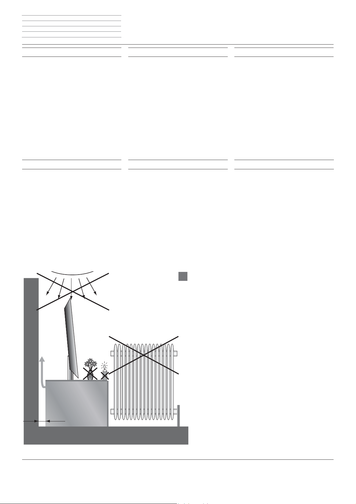
Stellen Sie Ihr Rack nicht in der Nähe von Wärmequellen wie Heizkörpern auf (Abb. 1). Auch sollte
direkte Sonneneinstrahlung vermieden werden.
Achten Sie auf ausreichende Luftzufuhr für die im
Rack eingestellten Geräte.
Es muss daher ein Abstand von der Rückseite des
Racks bis zur Wand von mindestens 3 cm eingehalten werden. Die Öffnungen im Rack müssen
frei bleiben und dürfen nicht abgedeckt werden.
Tragen Sie das Rack zu zweit an den vorgesehenen Aufstellort und packen Sie es aus.
Consignes de sécurité
Ne transportez pas le rack en positionnant l‘avant
vers le bas. L‘avant pourrait alors s‘ouvrir.
Ne posez pas votre rack proche d‘une source de
chaleur, comme un radiateur (ill. 1). Evitez également tout ensoleillement direct.
Veillez à une bonne ventilation pour les appareils
installés dans votre Rack. Un espace de 3 cm
minimum doit donc être respecté entre l‘arrière
du rack et le mur. Les oriÆ ces du rack doivent
rester libres et ne doivent pas être obturés.
Portez le rack à deux jusqu‘à l‘endroit prévu et
sortez-le de son emballage.
d
f
Veiligheidsvoorschriften
Transporteer het rack nooit met het front naar beneden gericht. Het front zou open kunnen gaan.
Installeer uw Rack niet in de buurt van warmtebronnen zoals verwarmingselementen (afb.1).
Ook rechtstreeks zonlicht moet worden vermeden.
Zorg voor voldoende luchttoevoer voor de in het
Rack opgestelde apparaten. Daarvoor dient u tussen de achterkant van het rack en de wand een
afstand van minstens 3 cm te laten. De openingen in het rack moeten vrij blijven en mogen niet
afgedekt worden.
Draag het rack met de hulp van een tweede persoon naar de voorziene opstelplaats en pak
het uit.
Indicazioni di sicurezza
Durante il trasporto non tenere il rack con la
sezione frontale rivolta verso il basso. La sezione
frontale potrebbe aprirsi.
Non montare il rack nelle vicinanze di fonti di
calore, come ad es. i termosifoni (Æ g. 1). Evitare
anche la luce solare diretta.
Accertarsi che sia disponibile un apporto di aria
sufÆ ciente per gli apparecchi da inserire Rack.
Rispettare una distanza di almeno 3 cm dal fondo
del rack Æ no alla parete. Le aperture nel rack
devono rimanere libere e non vanno coperte.
Il rack deve essere trasportato sul luogo di montaggio da due persone e quindi disimballato.
l
i
Safety Instructions
Do not move the rack with the front facing
downwards. The front could open.
Do not place your rack close to heat sources such
as radiators (Æ g. 1). Direct sunlight should
also be avoided.
Ensure adequate ventilation for the devices
located in the rack. A space from the rear of the
rack to the wall of at least 3 cm must therefore
be ensured. The openings in the rack must be
kept free and may not be covered.
Two people should carry the rack to the place
where it is to be installed and unpack it.
Indicaciones de seguridad
No transporte el mueble rack con la parte frontal
hacia abajo porque podría abrirse.
No coloque el mueble cerca de fuentes de calor
tales como radiadores de calefacción (Æ g. 1).
También deben evitarse los rayos directos del sol.
Asegúrese de que circula suÆ ciente aire por los
aparatos colocados en el Rack. Deberá mantenerse cierta distancia entre la parte posterior del
mueble y la pared (3 cm como mínimo). Los oriÆ
cios del mueble no deben cubrirse.
Transporte el mueble hasta el lugar de instalación
previsto con ayuda de otra persona y desempaquételo.
g
e
> 3 cm
Page 6
Rack - 6 -
Montageanleitung Instructions de montage
Montage-instructies Istruzioni di montaggio
Installation instructions Instrucciones de montaje
Zuordnung: Adapter zu TV-Gerät
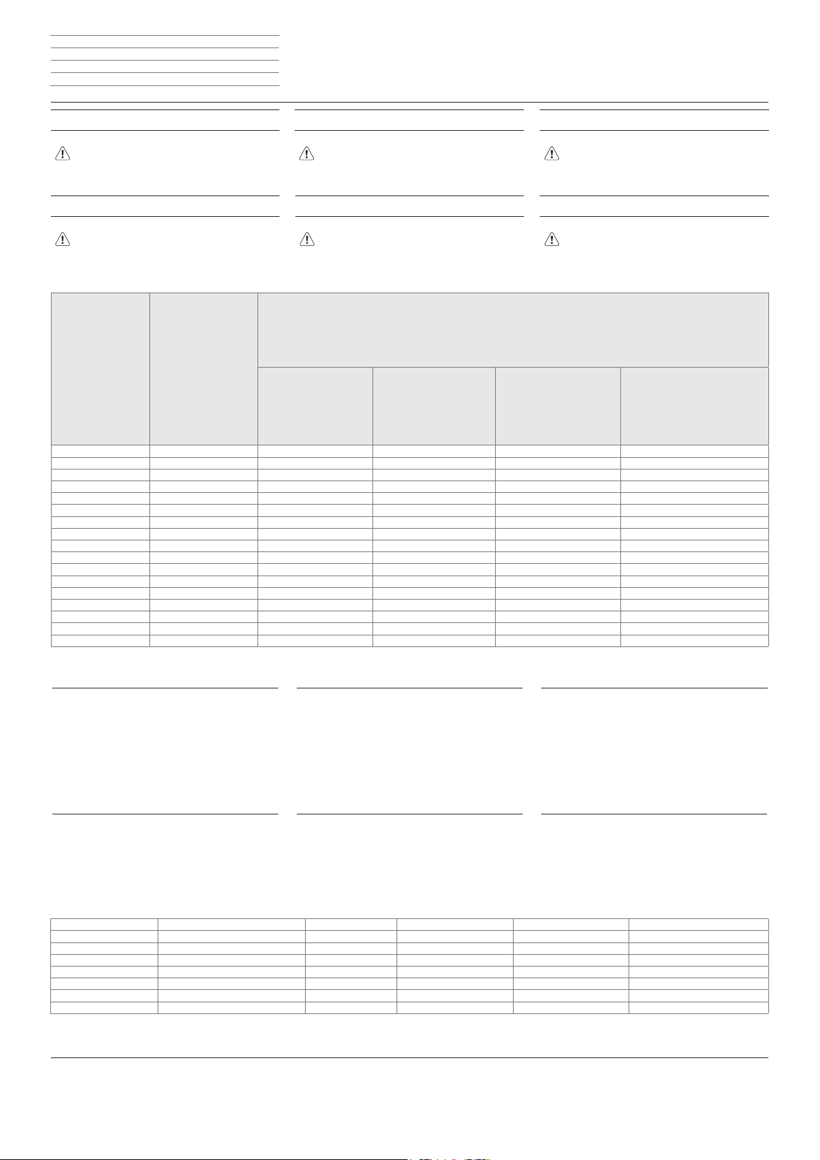
Die Tabelle zeigt, welche TV-Geräte auf dem Rack
montiert werden können und welche Adapter bei
der Montage benötigt werden.
Correspondance adaptateur-téléviseur
Le tableau indique les téléviseurs qui peuvent être
sur le rack ainsi que les adaptateurs nécessaires au
montage.
TV Artikelnummer TV
Codice articolo TV
TV part number
Référence téléviseur
Número de referencia
del televisor
d
f
Toewijzing: adapter aan tv-toestel
De tabel geeft aan welke tv-toestellen op het rack
kunnen worden gemonteerd en welke adapters u
nodig hebt voor de montage.
Applicazione: adattatore sull’apparecchio TV
Nella tabella sono elencati gli apparecchi TV che si
possono montare sul rack e gli eventuali adattatori
necessari al montaggio.
Manuell drehbar
A rotazione manuale
Handmatig draaibaar
Manually rotatable
Rotation manuelle
Giratorio a mano
Manuell mit Lautsprecher
Manuale con altoparlanti
Handmatig met luidspreker
Manually with speakers
Manuellement avec haut-parleur
Manual con altavoz
l
i
Assigning: Adaptor to TV sets
The table shows which TV devices can be installed
onto the rack and which adapters are required for
the installation.
Asignación: adaptador al televisor
La tabla muestra qué televisores pueden montarse
en el rack y qué adaptadores son necesarios para
el montaje.
Artikelnummer Adapter
Codice articolo adattatore
Artikelnummer adapter
Adapter part number
Référence adaptateur
Número de referencia del adaptador
Motorisch drehbar
A rotazione motorizzata
Motorisch draaibaar
Motor-driven rotation
Rotation motorisée
Giratorio a motor
Motorisch mit Lautsprecher
Motorizzata con altoparlanti
Motorisch met luidspreker
Motor-driven with speakers
Motorisé avec haut-parleur
A motor con altavoz
Individual 55 52403... 71504B00 71510B00 71518B00 71519B00
Individual 46 52402... 71504B00 71510B00 71518B00 71519B00
Individual 40 52401... 71504B00 71510B00 71518B00 71519B00
Connect ID 46 51464… 71357T00 – –
Connect ID 40 51463… 71357T00 – –
Connect ID 32 51462… 71357T00 – –
Connect 40 3D/LED 51409/50404... 71453T00 / (71042T00) – –
Connect 32 3D/LED 51408/50402... 71453T00 / (71042T00) – –
Art 46 3D/LED 51414/50416... 71453T00 / (71042T00) – –
Art 40 3D/LED 51413/50414... 71453T00 / (71042T00) – –
Art 37 LED 50413... 71453T00 / (71042T00) – –
Art 32 LED 50412... 71453T00 / (71042T00) – –
Xelos 40 LED 50424... 71453T00 / (71042T00) – –
Xelos 32 LED 50422... 71453T00 / (71042T00) – –
Xelos 46 52449... 71453T00 / (71042T50)
Xelos 40 51439... 71453T00 / (71042T50)
Xelos 32 51429... 71453T00 / (71042T50)
g
e
d
Zusätzlich können auch ältere TV-Geräte auf dem Rack
montiert werden (siehe untere Tabelle).
Die hierfür notwendigen Montageschritte entnehmen
Sie bitte der entsprechenden Anleitung. Diese können
Sie unter folgender Adresse herunterladen:
ftp://ftp.loewe.de/Assembly_Instructions/
.../51487T00_Rack 165.30
f
De plus, des téléviseurs plua anciens peuvent également
être montés sur le rack (voir tableau en dessous).
Veuillez consulter la notice correspondante pour connaître les opérations de montage nécessaires. Vous pouvez
télécharger la notice en utilisant l‘adresse suivante :
ftp://ftp.loewe.de/Assembly_Instructions/
.../51487T00_Rack 165.30
Daarnaast kunnen ook oudere tv-toestellen op het rack
worden gemonteerd (zie onderste tabel).
De daartoe vereiste montagestappen vindt u in de
betreffende handleiding. Die kunt u downloaden op het
volgende adres:
ftp://ftp.loewe.de/Assembly_Instructions/
.../51487T00_Rack 165.30
Sul rack è possibile montare anche apparecchi TV più
vecchi (vedere la tabella in basso).
I passaggi necessari al montaggio sono descritti nelle
rispettive istruzioni. Le istruzioni si possono scaricare
dal sito:
ftp://ftp.loewe.de/Assembly_Instructions/
.../51487T00_Rack 165.30
l
i
Older TV sets can also be installed onto the rack (see
the table below).
See the corresponding instructions for the necessary installation steps. You can download this at the following
address:
ftp://ftp.loewe.de/Assembly_Instructions/
.../51487T00_Rack 165.30
También pueden montarse televisores más antiguos en
el rack (ver tabla inferior).
Consulte los pasos de montaje necesarios en el manual
correspondiente. Puede descargarlo en la siguiente
dirección:
ftp://ftp.loewe.de/Assembly_Instructions/
.../51487T00_Rack 165.30
Individual 55 3D/LED 50432/69410... 51490B00 – – –
Individual 46 3D/LED 50431/69419/69409... 51490B00 50499B00 – –
Individual 40 3D/LED 50430/69418/69408... 51490B00 50499B00 – –
Individual 32 3D/LED 51425/69415... – 50498B00 – –
Connect 42/37 68436/68435... 70107B00 – – –
Connect 32 68417... 70238B00 – – –
Art 47/42/37/32 SL 68403/68402/68423/68401... 70465T00 – – –
Xelos 42/37/32 SL 69416/69414/69413... 70465T00 – – –
g
e
Page 7
Rack - 7 -
Montageanleitung Instructions de montage
Montage-instructies Istruzioni di montaggio
Installation instructions Instrucciones de montaje
Lieferumfang
Contenu de la livraison
A
B
d
f
Leveringsinhoud
Dotazione
l
i
Scope of Supply
Volumen de suministro
g
e
d
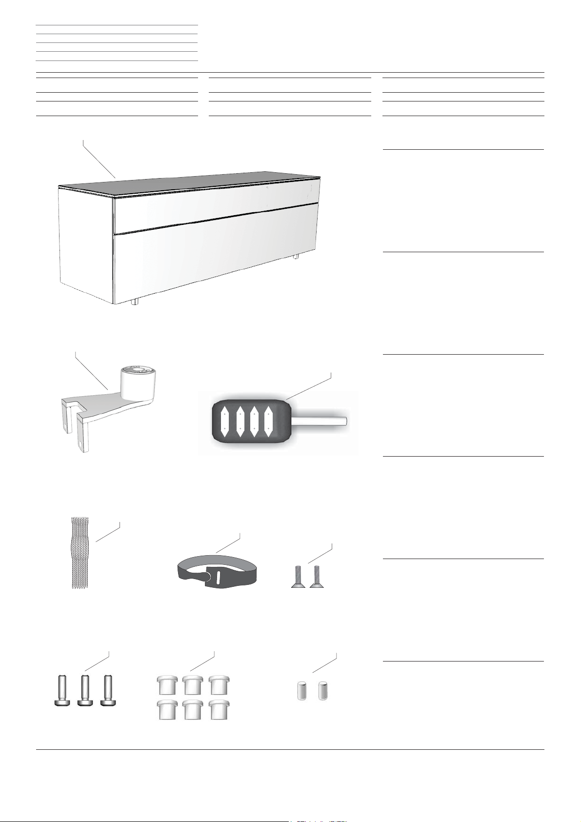
A Rack
B 1 Stk. TV Halterung
C 1 Stk. 4-Fach Netzverteiler
D 1x GeÇ echtschlauch
E 1x Klettkabelbinde
F 2x Senkschrauben (M5x20)
G 3x Innensechskant (M6x30)
H 6x Abdeckkappen
I 2x Zentrierstifte
l
A Rack
B 1 st. TV-houder
C 1 st. 4-voudige netverdeler
D 1x textielslang
E 1x klittenbandkabelbinder
F 2x verzonken schroeven (M5x20)
G 3x inbusschroeven (M6x30)
H 6x afdekkapjes
I 2x centreerstiften
g
A Rack
C
B 1 x TV bracket
C 1 x 4-fold mains distributor
D 1x braided hose
E 1x Velcro cable tie
F 2x countersunk screws (M5x20)
G 3x hexagon socket (M6x30)
H 6x covering caps
I 2x centring pins
A Rack
f
B 1 support téléviseur
C 1 distributeur de réseau quadruple
D 1x gaine tressée
E 1x serre-câbles Velcro
F 2x vis à tête fraisée (M5x20)
G 3x clés Allen (M6x30)
D
E
F
G
H
I
H 6x capuchons protecteurs
I 2x ergots de centrage
i
A Rack
B 1 pz. supporto TV
C 1 pz. distributore rete quadruplo
D 1 passacavo intrecciato
E 1 fascetta fermacavi in velcro
F 2 viti a testa svasata (M5x20)
G 3 viti a esagono incassato (M6x30)
H 6 tappi protettivi
I 2 perni di centraggio
e
A Rack
B 1x Soporte de TV
C 1x Distribuidor de corriente con 4 tomas
D 1x Tubo Ç exible trenzado
E 1x Sujetacables de velcro
F 2x Tornillos avellanados (M5x20)
G 3x Cabeza hexagonal interior (M6x30)
H 6x Caperuzas para tornillos
I 2x Pasadores de centrado
Page 8
Rack - 8 -
1
2
3
1
2
3
1
2
3
1
2
3
1
2
3
1
2
3
1
2
3
Montageanleitung Instructions de montage
Montage-instructies Istruzioni di montaggio
Installation instructions Instrucciones de montaje
Montage TV-Halterung
Rack vorbereiten
Montage du support téléviseur
Préparation du rack
Montage von Individual 40-55 siehe Montageanleitung 35465 Individual 40-55 Table Floor Stand.
1
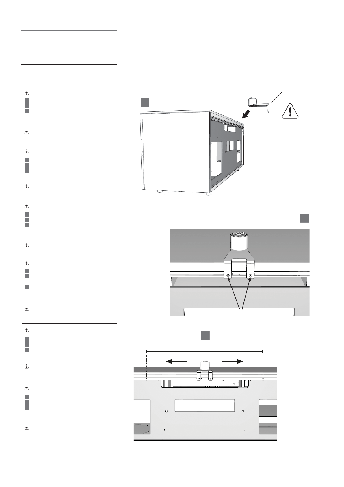
TV-Halterung (B) am Rack anbringen.
TV-Halterung mit zwei Schrauben (F) leicht Æ xieren.
Position der TV-Halterung wählen (im Bereich
zwischen L und R) und die beiden Schrauben
handfest andrehen.
Achtung. Es können leichte Schattierungen auf der
Rackoberseite auftreten, sollte die TV-Halterung
längere Zeit nicht in ihrer Position verändert werden
Montage van Individual 40-55, zie montage-instructies 35465 Individual 40-55 Table Floor Stand.
Breng de TV-houder (B) aan op het rack.
Bevestig de TV-houder lichtjes met twee schroeven (F).
Kies de positie van de tv-houder (in de zone tussen
L en R) en draai beide schroeven handvast aan.
Let op. Er kunnen lichte schakeringen ontstaan op
de bovenkant van het rack, wanneer de positie van
de TV-houder langere tijd niet gewijzigd wordt
For mounting of Individual 40-55 see installation instructions 35465 Individual 40-55 Table Floor Stand.
Attach TV bracket (B) on the rack.
Fasten TV bracket loosely with two screws (F).
Choose position of the TV bracket (in the area
between L and R) and fasten the two screws
hand tight.
Attention. Slight shadowing can occur on the rack
surface if the position of the TV bracket is not
changed for a longer period
Montage de Individuel 40 - 55, voir guide de montage 35465 Individual 40 -55 Table Floor Stand.
Poser le support téléviseur (B) sur le rack.
Fixer légèrement le support téléviseur à l’aide de
deux vis (F).
Sélectionner la position du support téléviseur (dans
la zone entre L et R) et serrer manuellement
les deux vis.
Attention. De légères nuances de couleur peuvent
apparaître sur la surface du rack si le support téléviseur garde sa position sur une période prolongée
Per il montaggio di Individual 40-55 vedere le
istruzioni per il montaggio 35465 Individual 40-55
supporto da tavolo a pavimento.
Appoggiare il supporto TV (B) sul rack.
Fissare leggermente il supporto TV con due viti (F).
Stabilire la posizione del supporto TV (nella zona
tra sx e dx) e serrare le due viti a mano.
Attenzione: si potrebbero evidenziare delle leggere
ombreggiature sulla parte superiore del rack qualora
la posizione del supporto TV non venisse modiÆ cata
per un periodo prolungato
Montaje de Individual 40-55, véanse las instrucciones de montaje 35465 Individual 40-55 Table Floor
Stand.
Colocar el soporte de TV (B) en el Rack.
Fijar levemente el soporte de TV con dos tornillos (F)
Elegir posición del soporte de TV (en el área
entre L y R) y apretar a mano ambos tornillos.
soporte de TV durante un tiempo prolongado
Atención: Pueden aparecer sombras en la parte
superior del Rack si no se cambia la posición del
soporte de TV durante un tiempo prolongado
d
f
d
l
g
f
i
e
Montage TV-houder
Rack voorbereiden
Montaggio del supporto TV
Predisposizione del rack
LR
l
i
TV bracket assembly
Rack preparation
Montaje del soporte de TV
Preparación del Rack
g
e
B
F
d Diese Information gilt nicht für TV-Geräte Individual Selection 46/40/32
Deze informatie geldt niet voor tv-toestellen Individual Selection 46/40/32
l
This information does not apply for TV sets Individual Selection 46/40/32
g
Cette information ne concerne pas les téléviseurs Individual Selection 46/40/32
f
Le presenti informazioni non valgono per gli apparecchi TV Individual Selection 46/40/32
i
Esta información no es válida para televisores 46/40/32
e
Page 9
Rack - 9 -
1
2
3
1
2
3
1
2
3
1
2
3
1
2
3
1
2
3
3
2
1
Montageanleitung Instructions de montage
Montage-instructies Istruzioni di montaggio
Installation instructions Instrucciones de montaje
Rack vorbereiten
Rack justieren
Préparation du rack
Ajustage du rack
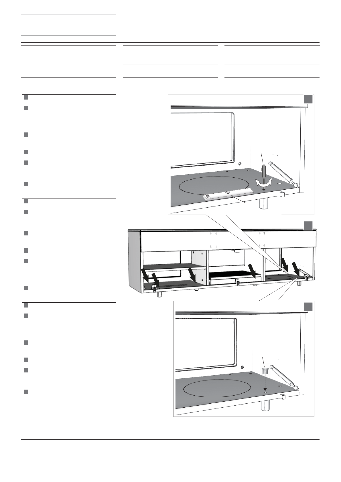
1
Im Rackinneren beÆ ndet sich über jedem Fuß
jeweils eine Justierschraube.
Justierschrauben mit Schraubenschlüssel SW 4 (S)
nach links oder rechts drehen, bis das Rack in der
waagrechten Position ist.
Hinweis. Zum Justieren eine Wasserwage (W)
verwenden.
Nach dem Justieren die Löcher mit den Abdeck kappen (H) verschließen.
Binnenin het rack bevindt zich boven iedere voet
telkens een stelschroef.
Draai de stelschroeven met een schroevendraaier
SW 4 (S) naar links of naar rechts, tot het rack in de
horizontale positie staat. Opmerking. Voor het
afstellen een waterpas (W) gebruiken.
Dek de gaten na het afstellen af met behulp van
de afdekkappen (H).
An adjusting screw is located inside the rack above
every foot.
Turn adjusting screw using a spanner width-across Ç ats 4 (S) to the left or right until the rack is in a
horizontal position.
Note. use a spirit level (W) for the adjustment.
After adjustment, close up the holes with the
covering caps (H).
Au-dessus de chaque pied à l’intérieur du rack se
trouve une vis de réglage.
Visser les vis de réglage à l’aide de la clé SW 4 (S)
en tournant vers la gauche ou vers la droite jusqu’à
ce que le rack soit à l‘horizontale.
Remarque. Utiliser un niveau à bulle (W)
pour procéder à l’ajustage.
Une fois l’ajustage terminé, obturer les oriÆ ces à
l‘aide des capuchons protecteurs (H).
All’interno del rack, su ciascun piede
è prevista una vite di regolazione.
Girare le viti di regolazione con l’apposita chiave
inglese SW 4 (S) verso sinistra o destra Æ no
a quando il rack è in posizione orizzontale.
Nota: per una corretta regolazione utilizzare una
livella (W) precedentemente rimosse.
Una volta eseguita la regolazione, chiudere i fori
con i tappi protettivi (H).
averseEn el interior del Rack se encuentra sobre
cada pie un tornillo de ajuste.
Girar los tornillos de ajuste con una llave de ancho
4 (S) hacia la izquierda o derecha hasta que el
Rack esté en posición horizontal.
Nota: Utilizar un nivel de agua (W) para el ajuste.
Cerrar los agujeros tras el ajuste con las
caperuzas (H).
d
f
d
l
g
f
i
e
Rack voorbereiden
Rack afstellen
Predisposizione del rack
Regolazione del rack
l
i
Rack preparation
Rack adjustment
Preparación del Rack
Ajuste del Rack
S
W
H
g
e
Page 10

Rack - 10 -
1
2
1
2
1
2
1
2
1
2
1
2
1
2
Montageanleitung Instructions de montage
Montage-instructies Istruzioni di montaggio
Installation instructions Instrucciones de montaje
Connect, Art, Xelos 46-32 LED/3D
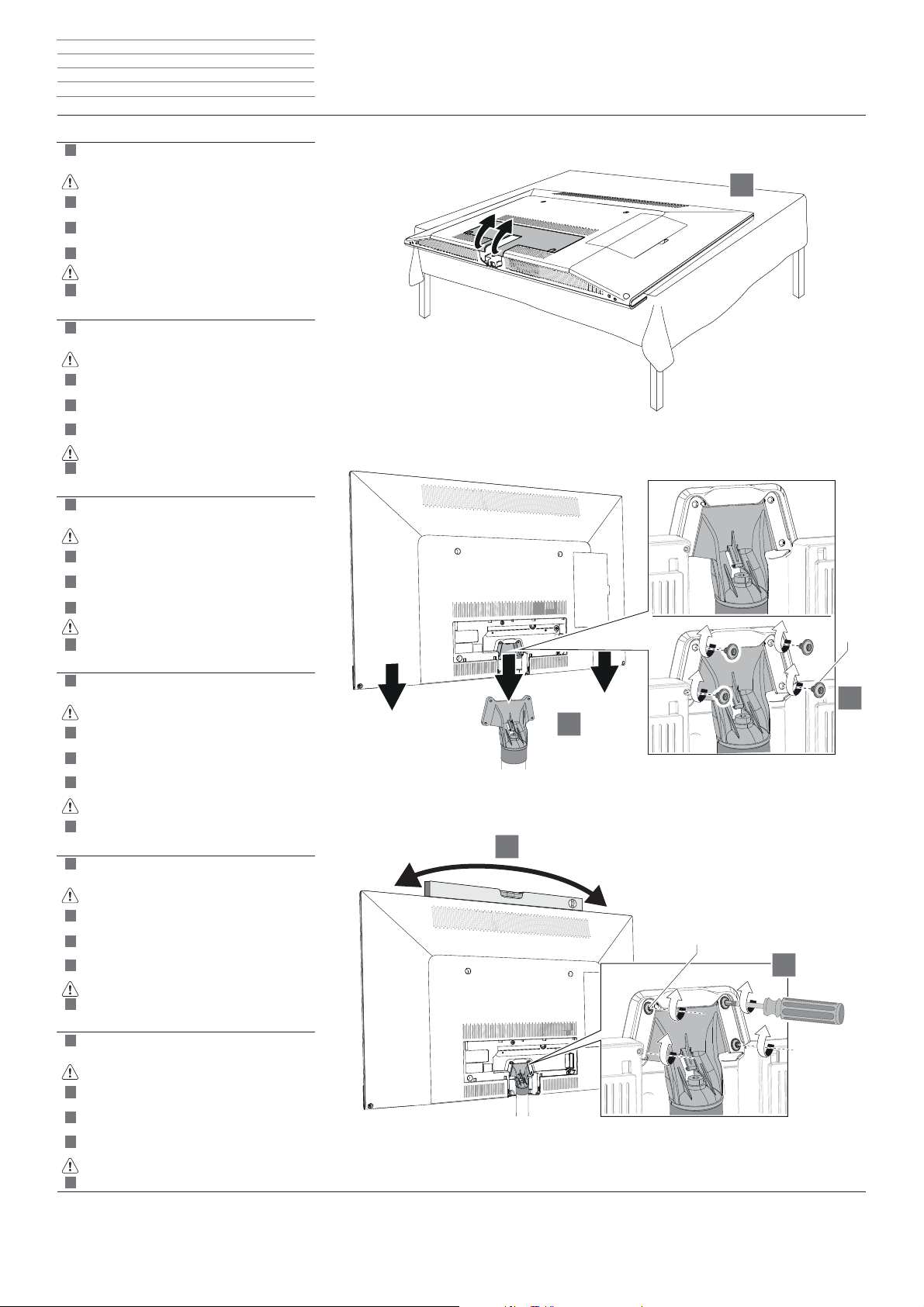
Standfuß demontieren
Connect, Art, Xelos 46-32 LED/3D
Démontage du pied
Die drei Schrauben mit einem Schraubenschlüssel
(T20) lösen.
Eine zweite Person zur Hilfe nehmen.
TV-Gerät nach oben abnehmen und mit der
Bildschirmseite auf eine weiche Unterlage (Vlies
oder Decke) ablegen.
Draai de drie schroeven met een schroevendraaier
(T20) los.
Roep de hulp van een tweede persoon in.
Neem het TV-toestel naar boven toe af en leg het
met de schermzijde neer op een zachte ondergrond
(vlies of deken).
Loosen the three screws using a spanner (T20).
Enlist a second person for help.
Remove TV set upwards and place down with
with the screen on a soft base (Ç eece
or blanket).
Desserrer les trois vis à l’aide d’une clé (T20).
Demander l’aide d’une deuxième personne.
Retirer le téléviseur par le haut et le déposer
avec le côté de l’écran sur un support souple
(non-tissé ou couverture).
1
1
1
d
f
d
l
g
f
Connect, Art, Xelos 46-32 LED/3D
Voet monteren
Connect, Art, Xelos 46-32 LED/3D
Smontaggio del piedistallo
l
i
Connect, Art, Xelos 46-32 LED/3D
Disassemble standing foot
Connect, Art, Xelos 46-32 LED/3D
Desmontaje del pie
A
g
e
Allentare le tre viti con una chiave inglese (T20).
Farsi aiutare da un’altra persona.
Sollevare l’apparecchio TV verso l’alto e
appoggiarlo dal lato dello schermo su una superÆ cie
morbida (tessuto-non-tessuto oppure su una
1
coperta).
AÇ ojar los tres tornillos con una llave (T20).
Solicitar la ayuda de otra persona.
Retirar el televisor hacia arriba y
colocarlo sobre una superÆ cie blanda (Æ eltro o
manta) con la pantalla hacia abajo.
1
i
e
1)
d Als Beispiel beschrieben am TV-Gerät Connect 40 LED/3D.
l Als voorbeeld beschreven op het tv-toestel Connect 40 LED/3D.
g The description uses the TV set Connect 40 LED/3D as an example.
f Le téléviseur Connect 40 LED/3D sert ici d’exemple.
i A titolo esempliÆ cativo viene descritta la procedura per l’apparecchio TV Connect 40 LED/3D.
e Se utiliza como ejemplo el televisor Connect 40 LED/3D.
Page 11
Rack - 11 -
1
2
4
3
1
2
3
4
1
2
3
4
1
2
3
4
1
2
3
4
1
2
3
4
1
2
3
4
Montageanleitung Instructions de montage
Montage-instructies Istruzioni di montaggio
Installation instructions Instrucciones de montaje
Connect, Art, Xelos 46-32 LED/3D
TV auf Rack montieren
Connect, Art, Xelos 46-32 LED/3D
Montage du téléviseur sur le rack
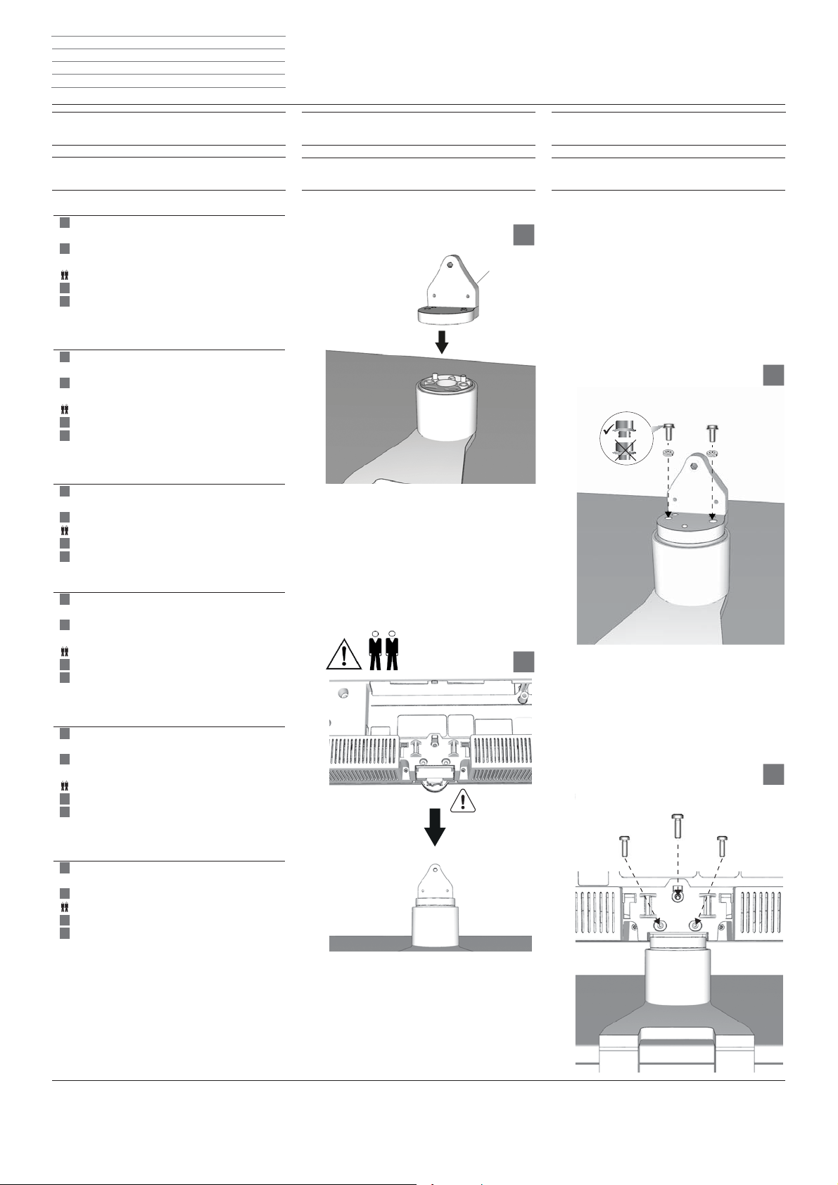
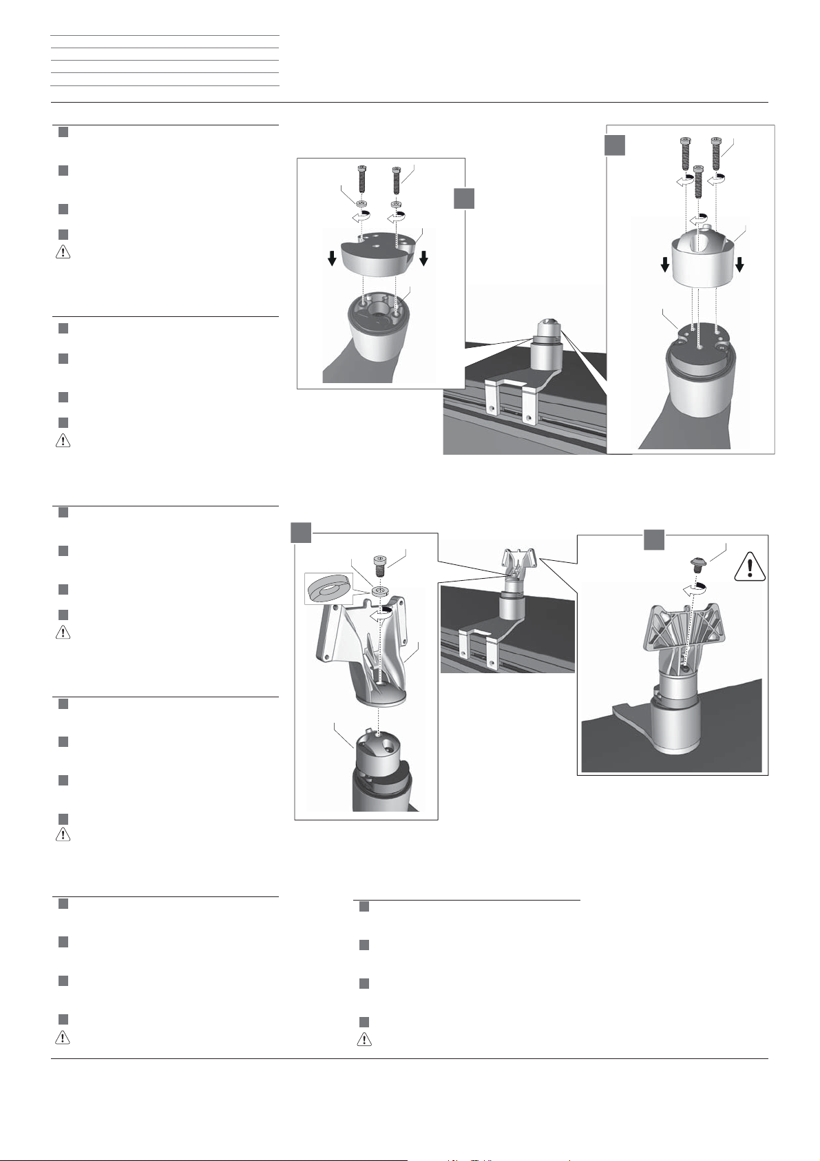
Zentrierstifte einsetzen und Adapter (A) auf die TV Halterung montieren.
Adapter mit zwei Schrauben (b1, b2) handfest
Æ xieren.
Eine zweite Person zur Hilfe nehmen.
TV-Gerät auf das Rack setzen.
TV-Gerät mit vorher entfernten Schrauben
befestigen.
Breng de centreerstiften aan en monteer de adapter
(A) op de TV-houder.
Adapter met twee schroeven (b1, b2) handvast
bevestigen.
Roep de hulp van een tweede persoon in.
Plaats het tv-toestel op het rack.
TV-toestel met eerder verwijderde schroeven
bevestigen.
Insert centring pins and and mount adapter (A) on
the TV bracket.
Fasten adapter hand tight with two screws (b1, b2).
Enlist a second person for help.
Place TV set on the rack.
Fasten TV set using the screws previously removed.
d
f
d
l
g
Connect, Art, Xelos 46-32 LED/3D
TV op rack monteren
Connect, Art, Xelos 46-32 LED/3D
Montaggio dell‘apparecchio TV sul rack
l
i
Connect, Art, Xelos 46-32 LED/3D
Mount TV on rack
Connect, Art, Xelos 46-32 LED/3D
Montaje del TV en el Rack
g
e
A
b1
b2
Placer les ergots de centrage et monter l’adaptateur
(A) sur le support téléviseur.
Visser l’adaptateur à la main avec les deux vis
(b1, b2).
Demander l’aide d’une deuxième personne.
Poser le téléviseur sur le rack.
Fixer le téléviseur à l’aide des vis
retirées précédemment.
Inserire i perni di centraggio e l’adattatore (A) nel
supporto TV.
Fissare l’adattatore con due viti (b1, b2) stringendolo
a mano.
Farsi aiutare da un’altra persona.
Appoggiare l’apparecchio TV sul rack.
Fissare l’apparecchio TV con le viti precedentemente
rimosse.
Colocar los pasadores de centrado y montar el
adaptador (A) en el soporte de TV.
Fijar el adaptador a mano con dos tornillos (b1, b2).
Solicitar la ayuda de otra persona.
Colocar el televisor en el Rack.
Fijar el televisor con los tornillos
retirados anteriormente.
f
i
f2
f1 f1
e
Page 12

Rack - 12 -
3
1
2
1
2
3
1
2
3
1
2
3
1
2
3
1
2
3
1
2
3
Montageanleitung Instructions de montage
Montage-instructies Istruzioni di montaggio
Installation instructions Instrucciones de montaje
Connect, Art, Xelos 46-32 LED/3D
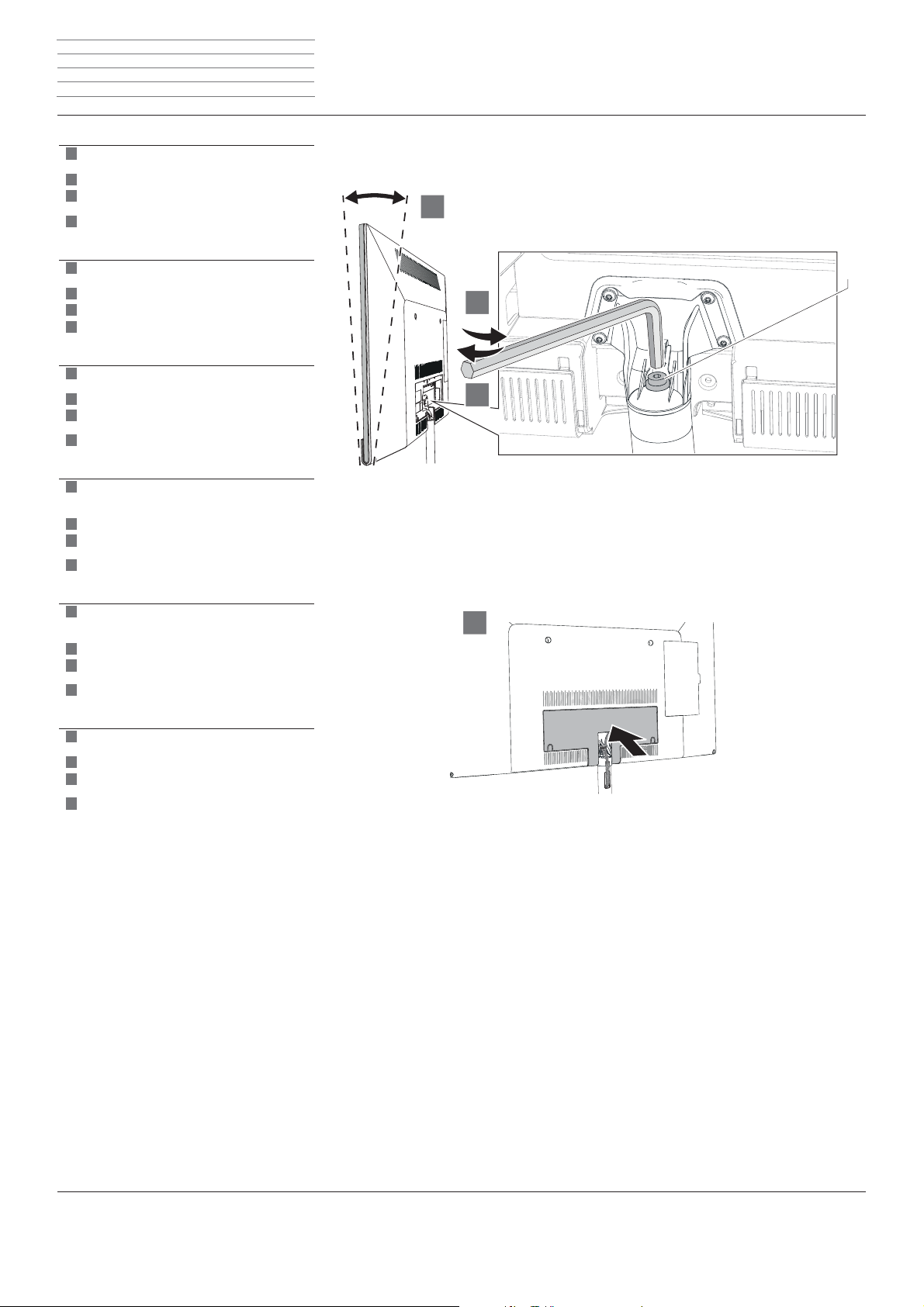
TV-Gerät neigen
Connect, Art, Xelos 46-32 LED/3D
Inclinaison du téléviseur
Um Neigewinkel des TV-Geräts (2,5°-5°) einzustellen, Imbusschlüssel in Loch X1 stecken und bis zum
Anschlag drehen:
nach links : Neigewinkel 5°,
nach rechts : Neigewinkel 2,5°.
Schraube S (Lieferumfang) mit aufbewahrte Beilagscheibe in X1 einstecken und handfest anschrauben
Kabelfachabdeckung wieder einsetzen
Om de hellingshoek van het tv-toestel (2,5°-5°) in te
stellen, inbussleutel in gat X1 steken en tot aan de
anslag draaien:
naar links : hellingshoek 5°,
naar rechts : hellingshoek 2,5°.
Schroef S (levering) met bewaarde bijlegschijf in X1
steken en handvast vastschroeven.
Breng de kabelvakafdekking opnieuw aan.
To set the tilt angle of the TV set (2.5° - 5°), insert
the Allen wrench into hole X and rotate until stop:
Towards the left: Tilt angle 5°,
Towards the right: Tilt angle 2.5°.
Insert screw S (included with delivery) with the
washer that was previously saved into X1 and hand
tighten
Reinsert the cable compartment cover.
d
f
d
l
g
Connect, Art, Xelos 46-32 LED/3D
Instellen van de hellingshoek
Connect, Art, Xelos 46-32 LED/3D
Inclinazione dell’apparecchio TV
5°
2,5°
l
i
5°
Connect, Art, Xelos 46-32 LED/3D
Tilting the TV set
Connect, Art, Xelos 46-32 LED/3D
Inclinar el televisor
X1
2,5°
g
e
S
Pour régler l’angle d’inclinaison du téléviseur (2,5°5°), enÆ cher la clé à six pans dans le trou X1 et
tourner jusqu’en butée :
vers la gauche : angle d’inclinaison de 5°,
vers la droite : angle d’inclinaison de 2,5°.
Placer la vis S (fournie dans la livraison) avec la
rondelle dans X1 et visser à la main.
Replacer le couvercle du compartiment de câbles.
Per impostare l’angolo di inclinazione dell’apparecchio TV (2,5°-5°), inÆ lare la chiave a brugola nel
foro X1 e girare Æ no allo scatto:
verso sinistra: angolo di inclinazione 5°,
verso destra: angolo di inclinazione 2,5°.
Inserire la vite S (compresa nella fornitura) con la
rondella conservata in X1 e stringere manualmente.
Applicare nuovamente il coperchio del vano cavi
Para ajustar el ángulo de inclinación del televisor
(2,5°- 5°), insertar una llave Allen en el oriÆ cio X1 y
girarla hasta el tope:
hacia la izquierda: ángulo de inclinación de 5°,
hacia la derecha: ángulo de inclinación de 2,5°.
Poner de nuevo en X1 el tornillo S (incluido en el
suministro) con la arandela retirada y apretarlo con
la mano
Volver a colocar la cubierta del compartimento de
cables.
f
i
e
Page 13

Rack - 13 -
1
2
1
2
1
2
1
2
1
2
1
2
1
2
Montageanleitung Instructions de montage
Montage-instructies Istruzioni di montaggio
Installation instructions Instrucciones de montaje
Xelos 32/40/46
TV auf Rack montieren
Xelos 32/40/46
Montage du téléviseur sur le rack
Zentrierstifte einsetzen und Adapter (A) auf die TV Halterung montieren.
Adapter mit zwei Schrauben (b1, b2) handfest
Æ xieren.
Breng de centreerstiften aan en monteer de adapter
(A) op de TV-houder.
Adapter met twee schroeven (b1, b2) handvast
bevestigen.
Insert centring pins and and mount adapter (A) on
the TV bracket.
Fasten adapter hand tight with two screws (b1, b2).
Placer les ergots de centrage et monter l’adaptateur
(A) sur le support téléviseur.
Visser l’adaptateur à la main avec les deux vis
(b1, b2).
Inserire i perni di centraggio e l’adattatore (A) nel
supporto TV.
Fissare l’adattatore con due viti (b1, b2) stringendolo
a mano.
d
f
d
l
g
f
i
Xelos 32/40/46
TV op rack monteren
Xelos 32/40/46
Montaggio dell‘apparecchio TV sul rack
l
i
Xelos 32/40/46
Mount TV on rack
Xelos 32/40/46
Montaje del TV en el Rack
g
e
A
Colocar los pasadores de centrado y montar el
adaptador (A) en el soporte de TV.
Fijar el adaptador a mano con dos tornillos (b1, b2).
e
b1
b2
Page 14

Rack - 14 -
4
3
4
5
3
4
5
3
4
5
3
4
5
3
4
5
3
4
5
3
5
Montageanleitung Instructions de montage
Montage-instructies Istruzioni di montaggio
Installation instructions Instrucciones de montaje
1 Schraube mit Beilagscheibe aus X1, 2 Schrauben
aus X2 herausschrauben und aufbewahren.
Standfuss vom TV-Gerät lösen und abziehen.
Montageschritt 5 gilt nur für TV-Geräte vom Typ
XELOS 32. Deren Neigewinkel (2,5°-5°) kann nur
vor dem Aufsetzen auf den Adapter (A) eingestellt
werden.
Imbusschlüssel in Stellschraube des Adapters einstecken und drehen bis diese bündig ist:
nach links : Neigewinkel 5°,
nach rechts : Neigewinkel 2,5°
1 schroef met bijlegeschijf X1, 2 schroeven uit X2
eruit schroeven en bewaren.
Standvoet van het tv-rack losmaken en lostrekken
Montagestap 5 is geldig alleen voor tv-toestellen
van het type XELOS 32. Hun hellingshoek (2,5°5°) kan alleen voor het opzetten op de adapter (A)
worden ingesteld.
Steek de inbussleutel in de stelschroef van de adapter
en draai tot deze volledig is ingedraaid:
naar links : hellingshoek 5°,
naar rechts : hellingshoek 2,5°
Remove 1 screw with washer from X1; 2 screws
from X2 and store them.
Loosen the stand base from the TV set and pull it
off
Assembly step 5 applies only for TV sets of type
XELOS 32. Their tilt angles (2.5° - 5°) can only be
set before the adaptor (A) is put on.
Insert the Allen wrench into the adaptor and rotate
until this is Ç ush:
Towards the left:Tilt angle 5°,
Towards the right: Tilt angle 2.5°
Dévisser et conserver 1 vis et la rondelle du trou X1
et les 2 vis du trou X2.
Desserrer le pied du téléviseur et le retirer.
L'étape de montage 5 s'applique uniquement
pour les téléviseurs de type XELOS 32. Le réglage
de leur angle d'inclinaison (2,5°-5°) ne peut être
réalisé qu'avant le montage sur l'adaptateur (A).
Placer la clé Allen dans la vis de réglage de l’adaptateur
et tourner pour serrer:
vers la gauche : angle d'inclinaison de 5°,
vers la droite : angle d'inclinaison de 2,5°
Svitare 1 vite con rondella da X1, 2 viti da X2 e
conservarle.
Allentare il piedistallo dall'apparecchio TV ed
estrarlo
La fase di montaggio 5 si applica solo ad appa-
recchi TV del tipo XELOS 32. Il suo angolo di
inclinazione (2,5°-5°) si può regolare solo prima del
posizionamento sull'adattatore (A).
Inserire la vite a brugola nella vite di regolazione
dell‘adattatore e ruotare Æ no a quando quest‘ultima
non è a Æ lo:
verso sinistra: angolo di inclinazione di 5°,
verso destra : angolo di inclinazione di 2,5°
d
l
g
f
i
5° 2,5°
X1
X2
5°
5°
2,5°
2,5°
Retirar 1 tornillo con arandela de X1 y 2 tornillos de
X2 y guardarlos.
Soltar el soporte de pie del televisor y retirarlo
La operación de montaje 5 se aplica exclusivamen-
te a los televisores del modelo XELOS 32. Su
ángulo de inclinación (2,5°-5°) solamente se puede
ajustar antes de colocarlo en el adaptador (A).
Insertar la llave Allen en el tornillo de ajuste del adaptador y girarla hasta que esté al ras:
hacia la izquierda: ángulo de inclinación de 5°,
hacia la derecha : ángulo de inclinación de 2,5°
e
Page 15
Rack - 15 -
6
7
8
6
7
8
6
7
8
6
7
8
6
7
8
6
7
8
76
8
Montageanleitung Instructions de montage
Montage-instructies Istruzioni di montaggio
Installation instructions Instrucciones de montaje
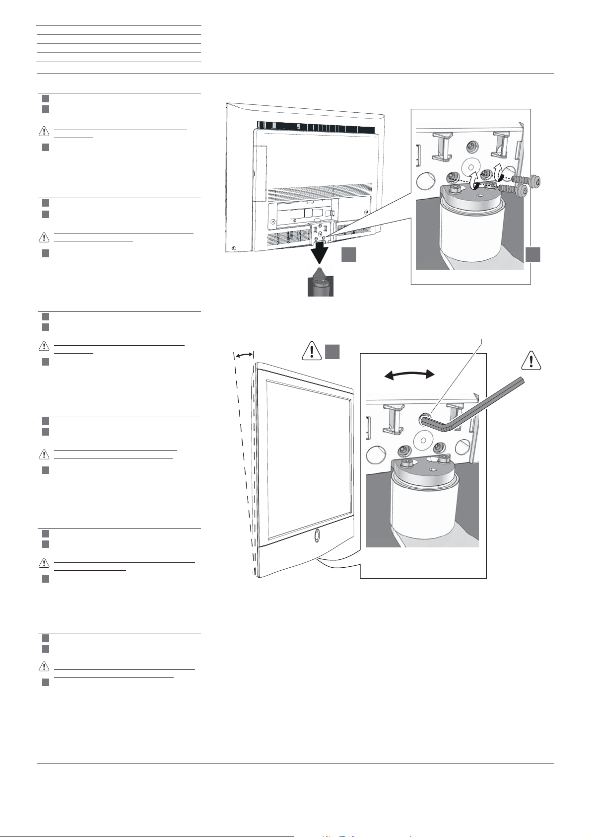
6
TV-Gerät auf Adapter (A) aufsetzen
Aufbewahrte Schrauben aus Löchern X2 wieder in
X2 einstecken und handfest anschrauben.
Montageschritt 8 gilt nur für TV-Geräte vom Typ
XELOS 40/46.
Um Neigewinkel des TV-Geräts (2,5°-5°) einzustellen,
Imbusschlüssel in Loch X1 stecken und bis zum
Anschlag drehen:
nach links : Neigewinkel 5°,
nach rechts : Neigewinkel 2,5°.
Tv-toestel op adapter (A) zetten
Bewaarde schroeven uit de gaten X2 weer in X2
steken en handvast vastschroeven
Montagestap 8 is geldig alleen voor tv-toestellen
van het type XELOS 40/46.
Om de hellingshoek van het tv-toestel (2,5°-5°) in te
stellen, inbussleutel in gat X1 steken en tot aan de
anslag draaien:
naar links : hellingshoek 5°,
naar rechts : hellingshoek 2,5°.
Set the TV set on adaptor (A)
Re-insert the screws saved from holes X2 back into
X2 and hand tighten
Assembly step 8 applies only for TV sets of type
XELOS 40/46.
To set the tilt angle of the TV set (2.5° - 5°), insert
the Allen wrench into hole X and rotate until stop:
Towards the left: Tilt angle 5°,
Towards the right: Tilt angle 2.5°.
d
l
g
5°
2,5°
X1
5°
2,5°
Placer le téléviseur sur l’adaptateur (A).
Remettre en place les vis conservées des trous X2
sur les trous X2 et visser à la main.
L’étape de montage 8 s’applique uniquement
pour les téléviseurs de type XELOS 40/46.
Pour régler l'angle d'inclinaison du téléviseur (2,5°5°), enÆ cher la clé à six pans dans le trou X1 et
tourner jusqu'en butée :
vers la gauche : angle d'inclinaison de 5°,
vers la droite : angle d'inclinaison de 2,5°.
Posizionare l’apparecchio TV sull’adattatore (A)
Riposizionare le viti estratte dai fori X2 in X2 e
stringerle manualmente
La fase di montaggio 8 si applica solo ad apparecchi
TV del tipo XELOS 40/46.
Per impostare l'angolo di inclinazione dell'apparecchio TV (2,5°-5°), inÆ lare la chiave a brugola nel foro
X1 e girare Æ no allo scatto:
verso sinistra: angolo di inclinazione 5°,
verso destra: angolo di inclinazione 2,5°.
Colocar el televisor en el adaptador (A)
Poner de nuevo en X2 los tornillos retirados de los
oriÆ cios X2 y apretarlos con la mano
La operación de montaje 8 se aplica exclusivamente
a los televisores del modelo XELOS 40/46.
Para ajustar el ángulo de inclinación del televisor
(2,5°-5°), insertar una llave Allen en el oriÆ cio X1 y
girarla hasta el tope:
hacia la izquierda: ángulo de inclinación de 5°,
hacia la derecha: ángulo de inclinación de 2,5°.
f
i
e
Page 16
Rack - 16 -
1
2
1
2
1
2
1
2
1
2
1
2
1
2
Montageanleitung Instructions de montage
Montage-instructies Istruzioni di montaggio
Installation instructions Instrucciones de montaje
Connect ID 46-32
TV auf Rack montieren
Connect ID 46-32
Montage du téléviseur sur le rack
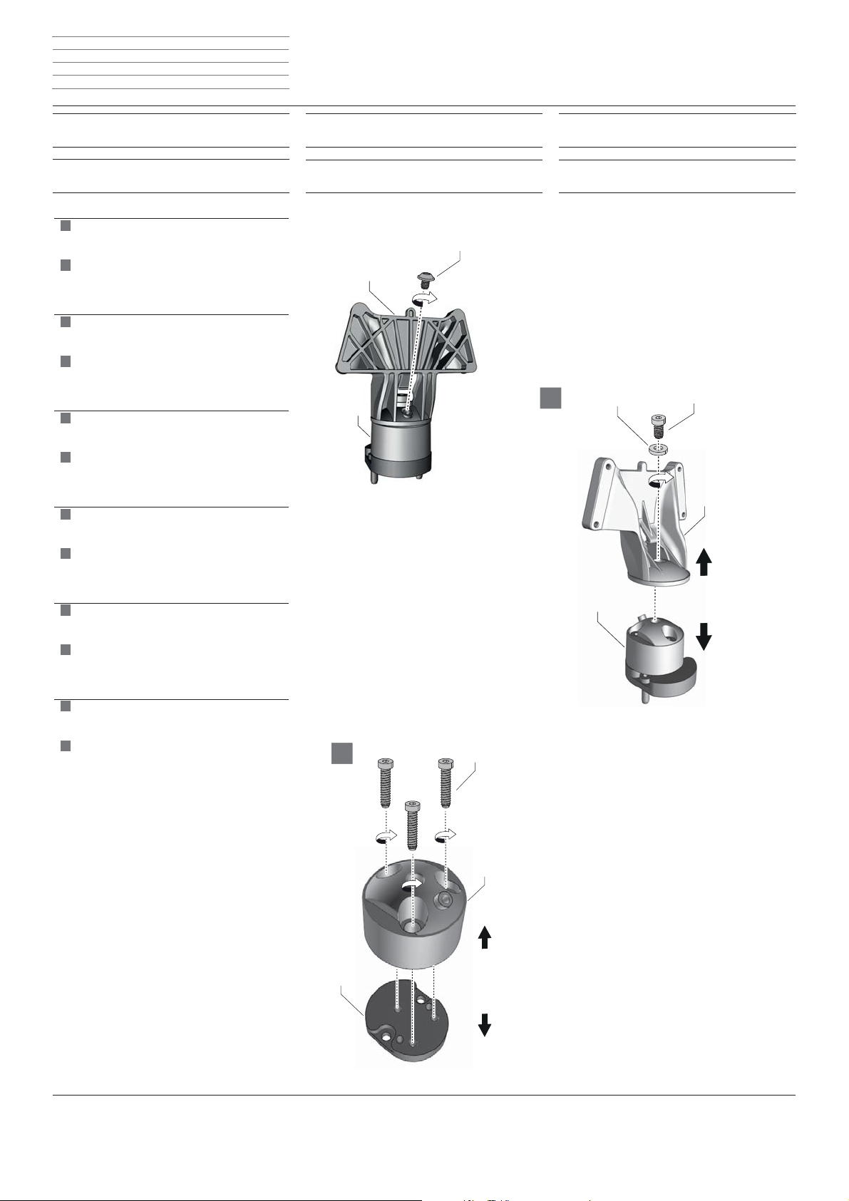
Um Adapterkopf (E) von Adapterbasis (F) zu
trennen, Schraube (L) und Schraube (J) mit
Scheibe (K) herausschrauben
Die drei Schrauben (H) lösen und Adapterbasis (F)
vom Adapterteil (G) trennen.
Om adapterkop (E) van adapterbasis (F) te
scheiden, schroef (L) en schroef (J) met schijf (K)
eruit schroeven
De drie schroeven (H) losdraaien en adapterbasis (F)
scheiden van het adapteronderdeel (G).
To separate the adaptor head (E) from the adaptor
base (F), unscrew screw (L) and screw (J) with
washer (K)
Loosen the three screws (H) and separate the
adapter base (F) from the adapter part (G).
Pour séparer la tête de l’adaptateur (E) de la base
de l’adaptateur (F), dévisser les vis (L) et (J) avec la
rondelle (K)
Dévisser les trois vis (H) et séparer la base de
l’adaptateur (F) de l’adaptateur (G).
d
f
d
l
g
f
Connect ID 46-32
TV op rack monteren
Connect ID 46-32
Montaggio dell‘apparecchio TV sul rack
L
E
F
l
i
Connect ID 46-32
Mount TV on rack
Connect ID 46-32
Montaje del TV en el Rack
1
K
g
e
J
E
Per separare la testina di adattamento (E) dalla base
dell’adattatore (F), svitare la vite (L) e la vite (J) con
la rondella (K)
Allentare le tre viti (H) e separare la base dell’
adattatore (F) dal componente dell’adattatore (G).
Para separar el cabezal adaptador (E) de la base del
adaptador (F), desatornillar el tornillo (L) y el tornillo
(J) con la arandela (K)
AÇ ojar los tres tornillos (H) y separar la base del
adaptador (F) del adaptador (G).
i
F
e
H
F
G
Page 17
Rack - 17 -
3
4
5
6
3
4
5
6
3
4
5
6
3
4
5
6
3
4
5
6
3
4
5
6
3
4
5
6
Montageanleitung Instructions de montage
Montage-instructies Istruzioni di montaggio
Installation instructions Instrucciones de montaje
Zwei Zentrierstifte (Z) einsetzen und Adapterteil (G)
mit Schrauben (I) und Scheiben (K) an der
Rackhalterung handfest anschrauben.
Adapterbasis (F) mit drei Schrauben (H) oben am
vorher montierten Adapterteil (G) handfest
anschrauben.
Adapterkopf (E) mit Schraube (J) und Scheibe (K) an
Adapterbasis (F) handfest anschrauben.
Sicherungschraube (L) handfest anschrauben.
Achtung! Sicherungsschraube (L) auf keinen Fall
wieder lösen!
Twee centreerstiften (Z) aanbrengen en adapteron
derdeel (G) met schroeven (I) en onderlegringen
(K) met de hand vastschroeven aan de rackhouder.
Adapterbasis (F) met drie schroeven (H) boven
aan het eerder gemonteerde adapteronderdeel (G)
handvast vastschroeven.
Adapterkop (E) met schroef (J) en schijf (K) aan
adapterbasis (F) handvast vastschroeven
Borgschroef (L) handvast vastschroeven
Let op! Borgschroef (L) in geen geval weer losma
ken!
Insert two centring pins (Z) and screw the adapter
part (G) hand-tight to the rack holder using the
screws (I) and washers (K).
Screw the adapter base (F) hand-tight onto the top
of the adapter part (G) that was previously installed
using three screws (H).
Screw the adaptor head (E) with screw (J) and disc
(K) to the adaptor base (F) hand tight
Screw on the retaining screw (L) hand tight
Warning! Do not loosen the retaining screw (L)
under any circumstances!
d
l
g
I
K
H
G
Z
G
K
J
E
F
L
Insérer deux ergots de centrage (Z) et visser à la
main l’adaptateur (G) avec les vis (I) et les
rondelles (K) sur le support du rack.
Visser à la main la base de l’adaptateur avec
trois vis (H) au-dessus de l’adaptateur (G)
monté précédemment.
Monter la tête de l’adaptateur (E) sur la base de
l’adaptateur (F) avec la vis (J) et la rondelle (K) et
serrer à la main.
Visser la vis de blocage (L) à la main.
Attention Ne jamais desserrer la vis de blocage (L) !
Inserire due perni di centraggio e serrare a mano
il componente dell’adattatore (G), con le viti (I)
e le rondelle (K) sul supporto del rack.
Avvitare a mano la base dell’adattatore (F) con
tre viti (H) nella parte superiore del componente
dell’adattatore (G) precedentemente montato.
Avvitare manualmente la testina di adattamento (E)
con la vite (J) e la rondella (K) alla base
dell’adattatore (F)
Stringere manualmente la vite di sicurezza (L)
Attenzione! Non allentare in nessun caso la vite di
sicurezza (L)
f
i
F
e
Colocar dos pasadores de centrado (Z) y atornillar
el adaptador (G) con tornillos (I) y arandelas (K)
al soporte del rack a mano.
Atornillar la base del adaptador (F) con tres tornillos
(H) encima del adaptador (G) previamente montado
a mano.
Atornillar con la mano el cabezal adaptador (E)
con un tornillo (J) y una arandela (K) a la base del
adaptador (F)
Apretar con la mano el tornillo de seguridad (L)
¡Atención! ¡No volver a soltar el tornillo de seguri
dad (L) bajo ninguna circunstancia!
Page 18
Rack - 18 -
7
8
11
7
8
9
I0
11
7
8
9
I0
11
7
8
9
I0
11
7
8
9
I0
11
7
8
9
I0
11
7
8
9
I0
11
9
10
Montageanleitung Instructions de montage
Montage-instructies Istruzioni di montaggio
Installation instructions Instrucciones de montaje
TV-Gerät auf weiche Unterlage legen und
Kabelfachabdeckung abnehmen
Achtung! TV-Gerät muss bei der Montage von 2
Personen gehalten werden!
TV-Gerät auf TV-Halter aufsetzen (hält ohne
Schrauben)
Flanschkopfschrauben (G) bis zum Anschlag
eindrehen – nicht festziehen!
TV-Gerät mit Wasserwaage horizontal ausrichten
Achtung! TV-Gerät vor Kratzschäden schützen
Flanschkopfschrauben (G) festziehen (handfest)
TV-toestel op zachte ondergrond leggen en afdekking van het kabelvak demonteren
Let op! TV-toestel moet bij de montage door 2
personen worden vastgehouden!
TV-toestel op TV-houder plaatsen (houdt zonder
schroeven)
Flenskopschroeven (G) tot aan de aanslag indraaien
- niet aantrekken!
TV-toestel met behulp van een waterpas horizontaal
uitrichten
Let op! TV-toestel beschermen tegen krassen
Flenskopschroeven (G) aantrekken (handvast)
Place the TV set on a soft underlay and
remove the cable compartment cover
Warning! The TV set must be held by 2 persons
when being installed!
Place the TV set on the TV holder (it holds without
screws)
Screw in the Ç ange head screws (G) as far as they
will go - do not tighten!
Align the TV set horizontally with a spirit level
Warning! Protect TV set from damage caused by
scratches
Tighten the Ç ange head screws (G) hand tight
Poser le téléviseur sur un support mou et
retirer le couvercle du compartiment de câbles.
Attention Pendant le montage, le téléviseur doit
être tenu par 2 personnes !
Positionner le téléviseur sur le support prévu à cet
effet (ne requiert pas de vis).
Insérer les vis à tête bridée (G) jusqu'en butée – ne
pas les serrer à fond !
Positionner le téléviseur horizontalement à l'aide
d'un niveau à bulles.
Attention Attention protéger le téléviseur des
éraÇ ures
Serrer les vis à tête bridée (G) (à la main).
Posare l’apparecchio TV su una base morbida e
rimuovere lo sportello copricavi
Attenzione! Durante il montaggio l’apparecchio TV
deve essere sostenuto da 2 persone!
Posizionare l’apparecchio TV sul supporto TV (sorreggerlo senza le viti)
Avvitare le viti a testa Ç angiata (G) Æ no all'arresto -
non stringere!
Allineare in orizzontale il televisore con l'ausilio di
una livella
Attenzione! Proteggere la TV da grafÆ
Stringere saldamente le viti a testa Ç angiata (G)
Colocar el televisor sobre una base blanda y
retirar la cubierta del compartimento de cables
¡Atención! ¡El televisor debe ser sostenido durante
el montaje por 2 personas!
Colocar el televisor en el soporte (se mantiene
sujeto sin tornillos)
Enroscar los tornillos avellanados (G) hasta el tope,
¡pero no apretar!
Nivelar el televisor horizontalmente con un nivel de
burbuja de aire
¡Atención! Proteger el televisor contra los arañazos
Apretar (a mano) los tornillos avellanados (G)
d
l
g
f
i
e
G
G
Page 19
Rack - 19 -
14
15
I2
I3
I4
I5
I2
I3
I4
I5
I2
I3
I4
I5
I2
I3
I4
I5
I2
I3
I4
I5
I2
I3
I4
I5
12
13
Montageanleitung Instructions de montage
Montage-instructies Istruzioni di montaggio
Installation instructions Instrucciones de montaje
Zum Einstellen des Neigungswinkels des TV-Geräts,
Schraube (J) mit Sechskantschlüssel SW5 etwas lösen
Gewünschten Neigungswinkel einstellen
Schraube (J) mit Sechskantschlüssel festziehen
(handfest)
Kabelfachabdeckung wieder einsetzen
Voor het instellen van de hellingshoek het tv-toestel
schroef (J) met inbussleutel SW5 iets losmaken
Gewenste hellingshoek instellen
Schroef (J) met inbussleutel vastdraaien (handvast)
Breng de kabelvakafdekking opnieuw aan
To set the tilt angle of the TV set, loosen screw (J)
slightly with the Allen wrench SW5
Set the required tilt angle
Tighten the screw (J) with the Allen wrench (hand
tight)
Reinsert the cable compartment cover
AÆ n de régler l’angle d’inclinaison du téléviseur,
desserrer légèrement la vis (J) à l’aide d’une clé à six
pans creux de 5.
Régler l'angle d'inclinaison souhaité.
Serrer la vis (J) à l'aide d'une clé à six pans creux (à
la main).
Replacer le couvercle du compartiment de câbles.
d
l
J
g
f
Per impostare l’angolo di inclinazione dell’apparecchio TV, allentare un po’ la vite (J) con la chiave
esagonale SW5
Regolare l'angolo di inclinazione desiderato
Stringere saldamente (manualmente) la vite (J) con
una chiave esagonale
Applicare nuovamente il coperchio del vano cavi
Para ajustar el ángulo de inclinación del televisor,
aÇ ojar un poco el tornillo (J) con una llave Allen SW5
Ajustar el ángulo de inclinación deseado
Apretar (con la mano) el tornillo (J) utilizando una
llave Allen
Volver a colocar la cubierta del compartimento de
cables
i
e
Page 20

Rack - 20 -
Montageanleitung Instructions de montage
Montage-instructies Istruzioni di montaggio
Installation instructions Instrucciones de montaje
Übersicht
Equipment
d
Sehr geherte Kunde,
wir möchten Sie darauf hinweisen, dass Sie die
Möglichkeit haben, optionale Aufrüstsätze für Ihr
Rack zu erwerben.
Eine Übersicht über die Aufrüstsätze Æ nden Sie in
der unten dargestellten Tabelle.
Aperçu
Equipement
f
Cher client,
Nous attirons votre attention sur le fait que
vous avez la possibilité de vous procurer des kits
d’extension en option pour votre rack.
Vous trouverez une vue d’ensemble des kits
d’extension dans le tableau ci-dessous.
Aufrüstsatz
Uitbreidingssets
Upgrade kits
Kits d‘extension
Artikelnummer
Artikelnummer
Article number
Réf. d’article
Kit di espansione
Kits de ampliación
Número de referencia
Overzicht
Equipment
Geachte klant,
Wij maken u graag attent op het feit dat u optio-
nele uitbreidingssets voor uw rack kunt kopen.
Een overzicht van de uitbreidingssets vindt u in de
hieronder getoonde tabel.
Descrizione generale
Equipaggiamento
Egregio Cliente,
Le facciamo presente che esiste la possibilità di
acquistare diversi kit di espansione per il Suo rack.
Nella tabella riportata in basso è proposta una
sintesi dei kit di espansione disponibili.
N. articolo
l
i
Overview
Equipment
g
Dear customer,
We wish to point out that you have the option of
purchasing upgrade kits for your rack.
You can Æ nd an overview of the upgrade kits in
the table shown below.
Resumen
Equipamiento
e
Estimado cliente:
Nos gustaría recordarle que tiene la posibilidad
de adquirir kits de ampliación opcionales para su
Rack.
Encontrará un resumen de los kits de ampliación
en la tabla mostrada abajo.
Rack
Rack 165.30 Rack 165.45 CS Rack 165.45 SP
Rear Cover Rack 165.30 51491W00
1
;
Rear Cover Rack 165.45 51494W00 –
Background Lighting Rack 51496W00
Interior Lighting Rack 51497B00
1
;
2
;
Center Speaker 66209X00 –
Sound Projector 69205X00 – –
1
) Die Kombination der Aufrüstsätze „Rear Cover
Rack“ und „Background Lighting Rack“ ist nicht
möglich
2
) Der Aufrüstsatz „Interior Lighting Rack“ ist nur in
Kombination mit Aufrüstsatz „Background Lighting
Rack“ verwendbar
1
) La combinaison des kits d'extension « Rear Cover
Rack » et « Background Lighting Rack » n'est pas
possible
2
) Le kit d'extension « Interior Lighting Rack » est
utilisable uniquement en combinaison avec le
kit d‘extension « Background Lighting Rack »
d
f
1
) De combinatie van de uitbreidingsset „Rear Cover
Rack“ en „Background Lighting Rack“ is niet
mogelijk
2
) De uitbreidingsset „Interior Lighting Rack“ is alleen in
combinatie met uitrustingsset „Background Lighting
Rack“ bruikbaar
1
) I kit di espansione "Rear Cover
Rack“ e "Background Lighting Rack“ non sono
abbinabili
2
) Il kit di espansione "Interior Lighting Rack“ è
utilizzabile soltanto in abbinamento con il kit di
espansione „Background Lighting Rack"
l
i
1
) The combination of upgrade kits "Rear Cover
Rack" and "Background Lighting Rack" is not
possible
2
) The upgrade kit "Interior Lighting Rack" can only
be used in combination with the upgrade kit
„Background Lighting Rack"
1
) La combinación de los kits de ampliación "Rear
Cover Rack" y "Background Lighting Rack" no es
posible
2
) El kit de ampliación "Interior Lighting Rack" solo
puede usarse en combinación con el kit de
ampliación "Background Lighting Rack"
––
1
;
1
;
2
;
;
1
;
1
;
–
–
;
g
e
Page 21
Rack - 21 -
Montageanleitung Instructions de montage
Montage-instructies Istruzioni di montaggio
Installation instructions Instrucciones de montaje
Rear Cover Rack
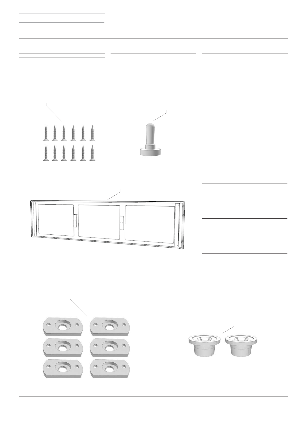
Lieferumfang
Rear Cover Rack
Contenu de la livraison
B
d
f
Rear Cover Rack
Inhoud van de levering
Rear Cover Rack
Dotazione
A
l
i
Rear Cover Rack
Scope of delivery
Rear Cover Rack
Volumen de suministro
g
e
d
A Rear Cover Rack
B 12x Schrauben (3,5x16)
C 6x Raststift
D 6x Raststifthalter
E 2x Blindlochverschluss
C
A Rear Cover Rack
B 12x schroeven (3,5x16)
C 6x arrêteerpen
D 6x arrêteerpenhouder
E 2x blindgatafdekking
l
g
A Rear Cover Rack
B 12x screws (3.5x16)
C 6x locking pin
D 6x locking pin holder
E 2x blind hole plug
f
A Rear Cover Rack
B 12x vis (3,5x16)
C 6x chevilles d’arrêt
D 6x supports de vis d’arrêt
E 2x caches pour trous borgnes
A Rear Cover Rack
B 12 viti (3,5x16)
C 6 perni di arresto
D 6 alloggiamenti perni di arresto
E 2 tappi per fori ciechi
e
A Rear Cover Rack
B 12x Tornillos (3,5x16)
C 6x Pasador de retención
D 6x Soporte de pasador de retención
E 2x Cierre de agujero ciego
D
E
i
Page 22
Rack - 22 -
1
2
3
4
5
1
2
3
4
5
1
2
3
4
5
1
2
3
4
5
1
2
3
4
5
1
2
3
4
5
2
1
3
4
5
3
Montageanleitung Instructions de montage
Montage-instructies Istruzioni di montaggio
Installation instructions Instrucciones de montaje
Rear Cover Rack
Montage
Rear Cover Rack
Montage
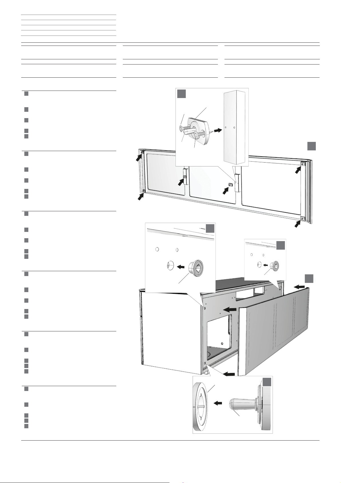
Raststift (C) in die Öffnung des Raststifthalters (D)
einführen und diesen mit zwei Schrauben (B) an der
Sichtrückwand befestigen.
Mit den anderen Raststiften (ingesamt 6 Stück)
in gleicher Weise verfahren.
Verschlusskappen (E) in die zwei Öffnungen am
Rack einsetzen.
Die Sichtrückwand am Rack befestigen
Die Raststifte (C) müssen in den Öffnungen der
Verschlusskappen (E) einrasten.
Arrêteerpen (C) in de opening van de
arrêteerpenhouder (D) steken en die met twee
schroeven (B) aan de sierachterwand bevestigen.
Met de andere arrêteerpennen (in het totaal 6 stuks)
op dezelfde wijze te werk gaan.
Afdekkappen (E) in de twee openingen op het
rack aanbrengen.
Bevestig de sierachterwand tegen het rack
De arrêteerpennen (C) moeten in de openingen van
de afdekkappen (E) verdwijnen.
Guide locking pin (C) into the opening of the locking
pin holder (D) and fasten this with two screws (B)
on the see-through rear panel.
Proceed in the same way with the other locking pins
(in total 6 items).
Insert locking caps (E) into the two openings on the
rack.
Fasten the see-through rear panel
The locking pins (C) must latch into the openings of
the locking caps (E).
Insérer la vis d’arrêt (C) dans l’ouverture du support
de vis d’arrêt (D) et Æ xer celle-ci à l‘aide de deux
vis (B) au panneau arrière.
Procéder de la même manière avec les autres vis
d’arrêt (6 au total).
Placer la plaquette d’obturation (E) dans les deux
oriÆ ces sur le rack.
Fixer le panneau arrière sur le rack
Les vis d’arrêt (C) doivent s’enclencher dans les
oriÆ ces des plaquettes d‘obturation (E).
Inserire il perno di arresto (C) nel foro dell’
alloggiamento perno (D) e Æ ssarlo con le due
viti sul retro lavorato a vista.
Procedere allo stesso modo con gli altri perni di
arresto (in totale 6 pezzi).
Inserire i tappi di chiusura (E) nei due fori del rack.
Fissare il retro lavorato a vista sul rack
Inserire i perni di arresto (C) nei fori dei
tappi di chiusura (E).
Introducir el pasador de retención (C) en el oriÆ cio
del soporte de pasador de retención (D) y Æ jarlo al
panel posterior presentable con dos tornillos (B).
Proceder del mismo modo con los otros pasadores
de retención (6 en total).
Colocar caperuzas de cierre (E) en los dos oriÆ cios.
Fijar el panel posterior presentable en el Rack
Los pasadores de retención (C) deben encajar en
los oriÆ cios de las caperuzas de cierre (E).
d
f
d
l
g
f
i
e
Rear Cover Rack
Montage
Rear Cover Rack
Montaggio
l
i
Rear Cover Rack
Installation
Rear Cover Rack
Montaje
g
e
B
C
D
B
E
E
E
C
Page 23
Rack - 23 -
1
2
3
4
1
2
3
4
1
2
3
4
1
2
3
4
1
2
3
4
1
2
3
4
1
2
3
4
Montageanleitung Instructions de montage
Montage-instructies Istruzioni di montaggio
Installation instructions Instrucciones de montaje
Center Speaker
Montage
Center Speaker
Montage
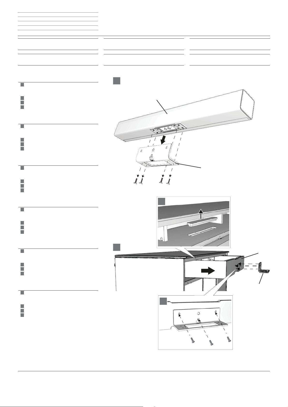
1
Wandhalter (W) vom Center Speaker demontieren.
Hierzu die vier Schrauben lösen und Wandhalter
abnehmen.
Träger (B) herausziehen.
Den Einleger der Belüftungsöffnung entfernen.
Den Wandhalter (A) am Träger (B) montieren und
mit drei Schrauben (G) Æ xieren.
Demonteer de wandhouder (W) van de Center
Speaker. Daarvoor moet u de vier schroeven
losdraaien en de wandhouder afnemen.
Drager (B) uittrekken.
Verwijder de inlegger van de ventilatieopening.
Monteer de wandhouder (A) op de drager (B) en
bevestig hem met drie schroeven (G).
Remove wall bracket (W) from the Center Speaker.
For this, loosen the four screws and take off the
wall bracket.
Pull out support (B).
Remove the insert from the ventilation opening.
Mount the wall bracket (A) on the support (B) and
fasten with three screws (G).
Démonter le support mural (W) du Center Speaker.
Retirer pour cela les quatre vis ainsi que le support
mural.
Retirer le support (B).
Retirer l’insert de l’ouverture d’aération.
Monter le support mural (A) sur le support (B) et
le Æ xer avec trois vis (G).
d
f
d
l
g
f
Center Speaker
Montage
Center Speaker
Montaggio
Center Speaker
l
i
Center Speaker
Installation
Center Speaker
Montaje
W
g
e
Smontare il supporto da parete (W) dal Center
Speaker. Per farlo, allentare le quattro viti ed
asportare il supporto da parete.
Estrarre l’elemento di appoggio (B).
Rimuovere l’innesto del foro di ventilazione.
Montare il supporto da parete (A) sull’elemento
di appoggio (B) e Æ ssarlo con le tre viti (G).
Desmontar el soporte de pared (W) del Center
Speaker. AÇ ojar para ello los cuatro tornillos y retirar
el soporte de pared.
Extraer el soporte (B).
Retirar el inserto del oriÆ cio de ventilación.
Montar el soporte de pared (A) en el soporte (B)
y Æ jar con tres tornillos (G).
i
e
B
W
G
G
G
Page 24

Rack - 24 -
5
6
7
5
6
7
5
6
7
5
6
7
5
6
7
5
6
7
7
5
6
Montageanleitung Instructions de montage
Montage-instructies Istruzioni di montaggio
Installation instructions Instrucciones de montaje
Center Speaker
Montage
Center Speaker
Montage
5
Center Speaker an den Wandhalter (W) montieren.
Zur Befestigung des Center Speakers die vorher
entfernten Schrauben verwenden. Die Kabel durch
die Öffnung am Wandhalter nach hinten führen.
Der Träger (mit Center Speaker) kann jetzt wieder
in das Rack geschoben werden.
Der Stereo Speaker im Rack kann nach Wunsch
in seiner Position verändert werden.
Monteer de Center Speaker op de wandhouder (W).
Gebruik voor het bevestigen van de Center Speaker
de eerder verwijderde schroeven. Leid de kabels
door de opening in de wandhouder naar achter toe.
De drager (met Center Speaker) kan nu weer
in het rack worden geschoven.
De Stereo Speaker in het rack kan naar wens
van positie worden veranderd.
Mount Center Speaker on the wall bracket (W).
Use the screws previously removed to fasten the
Center Speaker. Guide the cables through
the opening on the wall bracket to the rear.
The support (with Center Speaker) can now be slid
into the rack again.
The position of the Stereo Speaker in the rack can
be changed as desired.
d
f
d
l
g
Center Speaker
Montage
Center Speaker
Montaggio
l
i
Center Speaker
Installation
Center Speaker
Montaje
Center Speaker
g
e
W
Monter le Center Speaker sur le support mural (W).
Pour la Æ xation du Center Speaker, utiliser les
vis retirées précédemment. Introduire les câbles par
l’ouverture du support mural pour les faire passer à
l’arrière. Le support (avec le Center Speaker) peut
maintenant être de nouveau coulissé dans le rack.
La position du Stereo Speaker peut être
modiÆ ée dans le rack le cas échéant.
Montare il Center Speaker sul supporto da parete (W).
Per Æ ssare il Center Speaker, utilizzare le
viti precedentemente rimosse. InÆ lare i cavi nell’
apertura del supporto da parete dal lato posteriore.
A questo punto è possibile far scorrere l’elemento di
appoggio (con il Center Speaker)
far scorrere nuovamente nel rack.
La posizione dello Stereo Speaker nel rack
si può modiÆ care a propria discrezione.
Montar el Center Speaker en el soporte de pared (W).
Para la Æ jación del Center Speaker, utilizar
los tornillos retirados anteriormente. Guiar los
cables hacia atrás a través del oriÆ cio del soporte de
pared. El soporte (con Center Speaker) puede ahora
ser colocado de nuevo en el Rack.
La posición del Stereo Speaker en el Rack
puede modiÆ carse como se desee.
f
i
e
Page 25

Rack - 25 -
1
2
3
1
2
3
1
2
3
1
2
3
1
2
3
1
2
3
1
2
3
Montageanleitung Instructions de montage
Montage-instructies Istruzioni di montaggio
Installation instructions Instrucciones de montaje
Sound Projector
Montage
Sound Projector
Montage
1
Den Einleger der Belüftungsöffnung entfernen.
Träger (B) herausziehen.
Zur Montage des Sound Projectors wird der Wand halter (W) benötigt, der sich im Lieferumfang des
Sound Projectors beÆ ndet. Den Wandhalter (A)
am Träger (B) montieren und mit drei Schrauben (G)
Æ xieren.
Bei Montage ebenfalls die dem Sound Projector
beiliegende Anleitung beachten.
Verwijder de inlegger van de ventilatieopening.
Drager (B) uittrekken.
Voor het monteren van de Sound Projector hebt u
de wandhouder (W) nodig, die bij de Sound
Projector wordt geleverd. De wandhouder (A)
aan de drager (B) monteren en met drie schroeven
(G) bevestigen.
Bij montage eveneens de bij de Sound Projector
geleverde handleiding in acht nemen.
Remove the insert from the ventilation opening.
Pull out support (B).
To assemble the Sound Projector, you need the wall
bracket (W) included in the scope of supply of the
Sound Projector. Mount the wall bracket (A) on the
holder (B) and fasten with three screws (G).
During assembly also follow the instructions
enclosed with the Sound Projector.
Retirer l’insert de l’ouverture d’aération.
Retirer le support (B).
Le montage du Sound Projector s’effectue avec
le support mural (W) contenu dans la livraison du
Sound Projector. Monter le support mural (A)
sur le support (B) et Æ xer avec trois vis (G).
Observer lors du montage également la notice
jointe au Sound Projector.
Rimuovere l’innesto del foro di ventilazione.
Estrarre l’elemento di appoggio (B).
Per il montaggio del Sound Projector è indispensabile
il supporto da parete (W) in dotazione con il
Sound Projector. Montare il supporto da parete (A)
sull’elemento di appoggio (B) e Æ ssarlo con tre
viti (G) a mano.
Per il montaggio osservare anche in questo caso le
istruzioni allegate al Sound Projector.
Retirar el inserto del oriÆ cio de ventilación.
Extraer el soporte (B).
Para el montaje del Sound Projector se necesita
el soporte de pared (W) que se encuentra en el
volumen de suministro del Sound Projector. Montar
el soporte de pared (A) en el soporte (B) y Æ jar con
tres tornillos (G).
Tener en cuenta también el manual adjunto del
Sound Projector durante el montaje.
d
f
d
l
g
f
i
e
Sound Projector
Montage
Sound Projector
Montaggio
l
i
Sound Projector
Installation
Sound Projector
Montaje
g
e
B
W
G
G
G
Page 26

Rack - 26 -
4
5
6
7
4
5
6
7
4
5
6
7
4
5
6
7
4
5
6
7
4
5
6
7
4
5
6
7
Montageanleitung Instructions de montage
Montage-instructies Istruzioni di montaggio
Installation instructions Instrucciones de montaje
Sound Projector
Montage
Sound Projector
Montage
4
Verkabelung am Sound Projector vornehmen (siehe
Bedienungsanleitung des Sound Projectors).
Sound Projector wie dargestellt am Träger
einhängen.
Zur Befestigung die Sicherungsschraube aus dem
Beipack des Sound Projectros verwenden.
Der Träger (mit Sound Projector) kann jetzt wieder
in das Rack geschoben werden.
Der Sound Projector im Rack kann nach Wunsch
in seiner Position verändert werden.
Installeer de bekabeling van de Sound Projector (zie
de handleiding van de Sound Projector).
Sound Projector zoals getoond aan de drager
hangen.
Gebruik voor de bevestiging de borgschroef uit de
nevenverpakking van de Sound Projector.
De drager (met Sound Projector) kan nu weer
in het rack worden geschoven.
De Sound Projector in het rack kan naar wens
van positie worden veranderd.
Carry out cabling work for the Sound Projector (see
Instructions for Use of the Sound Projector).
Hook Sound Projector into the support as shown.
Use the locking screw from the accessories kit
of the Sound Projector. The support (with Sound
Projector) can now be slid into the rack again.
The position of the Sound Projector in the rack can
be changed as desired.
Procéder au câblage du Sound Projector (voir
le mode d’emploi du Sound Projector).
Accrocher le Sound Projector comme indiqué sur le
support.
Pour la Æ xation, utiliser la vis de sécurité contenue
dans le complément du Sound Projector.
Le support (avec le Sound Projector) peut maintenant
être de nouveau coulissé dans le rack.
La position du Sound Projector peut être
modiÆ ée dans le rack le cas échéant.
Eseguire il cablaggio del Sound Projector (vedi
le istruzioni di montaggio del Sound Projector).
Appendere il Sound Projector come illustrato sull’
elemento di appoggio.
Per il Æ ssaggio, utilizzare la vite di sicurezza
fornita con il Sound Projector.
L’elemento di appoggio (con il Sound Projector) si
può far scorrere far scorrere nuovamente nel rack.
La posizione del Sound Projector nel rack
si può modiÆ care a propria discrezione.
Realizar cableado del Sound Projector (consultar
manual de instrucciones del Sound Projector).
Colgar el Sound Projector en el soporte como
se muestra.
Para la Æ jación, utilizar el tornillo de
retención suministrado con el Sound Projector.
El soporte (con Sound Projector) puede ahora ser
colocado de nuevo en el Rack.
La posición del Sound Projector en el Rack
puede modiÆ carse como se desee.
d
f
d
l
g
f
i
e
Sound Projector
Montage
Sound Projector
Montaggio
l
i
Sound Projector
Installation
Sound Projector
Montaje
g
e
Page 27

Rack - 27 -
1
2
1
2
1
2
1
2
1
2
1
2
1
2
Montageanleitung Instructions de montage
Montage-instructies Istruzioni di montaggio
Installation instructions Instrucciones de montaje
Rack 165.30
Aufstellung
Rack 165.30
Installation
1
In allen Fächern, in die Geräte eingestellt werden
können, beÆ nden sich im Boden Belüftungs-
öffnungen. Diese sind durch Einleger verschlossen.
Vor dem Aufstellen der Geräte müssen die Einleger
entnohmen werden.
Equipmentkomponenten im Rack platzieren und
verkabeln (siehe Bedienungsanleitung des.
jeweiligen Gerätes). Für Stromanschluss die
beiliegende Steckdosenleiste verwenden.
In alle vakken waar toestellen in kunnen worden
geplaatst bevinden zich in de bodem verluchtings openingen. Die zijn met inleggers afgesloten.
Vóór het installeren van de toestellen moeten de
inleggers verwijderd worden.
Equipmentcomponenten in het rack plaatsen en
bekabelen (zie de handleiding van het
betreffende toestel). Voor stroomaansluiting de
bijgeleverde stopcontactenbalk gebruiken.
All compartments in which devices can be placed,
have ventilation openings in the base.
These are closed up by inserts. The inserts must be
removed before installing the units.
Position equipment components in the rack and
cable (see Instructions for Use of the
relevant device). Use the enclosed
outlet strip for the power connection.
Dans tous les compartiments dans lesquels des
appareils peuvent être réglés, se trouvent des
ouvertures d’aération au sol. Celles-ci sont fermées
par des inserts. Avant d‘installer les appareils, les
inserts doivent être retirés.
Placer et câbler les composants de l’équipement
dans le rack (se reporter à la notice d‘utilisation de
l’appareil correspondant). Pour le branchement
électrique, utiliser le bloc multiprises fourni.
In tutti gli scomparti adatti al montaggio di apparecchi
sono previsti appositi fori di ventilazione.
Questi sono chiusi con appositi innesti.
Prima di procedere con l’installazione degli
apparecchi, estrarre gli innesti.
Collocare i componenti dell’attrezzatura nel rack ed
eseguire il cablaggio (vedi il manuale di istruzioni
del rispettivo apparecchio). Per il collegamento
della corrente, utilizzare la presa multipla fornita.
En todos los compartimentos en los que se pueden
colocar dispositivos, se encuentran en el
el suelo unos oriÆ cios de ventilación. Estos están
cerrados con unos insertos. Estos deben retirarse
antes de colocar los dispositivos.
Colocar los componentes de equipamiento en el
Rack y realizar el cableado (consultar el
manual de instrucciones de cada dispositivo). Usar
la regleta suministrada para la conexión de corriente.
d
f
d
l
g
f
i
e
Rack 165.30
Opstelling
Rack 165.30
Installazione
BluTechVision
l
i
Rack 165.30
Set-up
Rack 165.30
Colocación
g
e
Individual Sound
Subwoofer
Page 28

Rack - 28 -
1
2
1
2
1
2
1
2
1
2
1
2
1
2
Montageanleitung Instructions de montage
Montage-instructies Istruzioni di montaggio
Installation instructions Instrucciones de montaje
Rack 165.45 CS
Aufstellung (mit Center Speaker)
Rack 165.45 CS
Installation (avec Center Speaker)
In allen Fächern, in die Geräte eingestellt werden
können, beÆ nden sich im Boden Belüftungs-
öffnungen. Diese sind durch Einleger verschlossen.
Vor dem Aufstellen der Geräte müssen die Einleger
entnohmen werden.
Equipmentkomponenten im Rack platzieren und
verkabeln (siehe Bedienungsanleitung des.
jeweiligen Gerätes). Für Stromanschluss die
beiliegende Steckdosenleiste verwenden.
In alle vakken waar toestellen in kunnen worden
geplaatst bevinden zich in de bodem verluchtings openingen. Die zijn met inleggers afgesloten.
Vóór het installeren van de toestellen moeten de
inleggers verwijderd worden.
Equipmentcomponenten in het rack plaatsen en
bekabelen (zie de handleiding van het
betreffende toestel). Voor stroomaansluiting de
bijgeleverde stopcontactenbalk gebruiken.
All compartments in which devices can be placed,
have ventilation openings in the base.
These are closed up by inserts. The inserts must be
removed before installing the units.
Position equipment components in the rack and
cable (see Instructions for Use of the
relevant device). Use the enclosed
outlet strip for the power connection.
Dans tous les compartiments dans lesquels des
appareils peuvent être réglés, se trouvent des
ouvertures d’aération au sol. Celles-ci sont fermées
par des inserts. Avant d‘installer les appareils, les
inserts doivent être retirés.
Placer et câbler les composants de l’équipement
dans le rack (se reporter à la notice d‘utilisation de
l’appareil correspondant). Pour le branchement
électrique, utiliser le bloc multiprises fourni.
In tutti gli scomparti adatti al montaggio di apparecchi
sono previsti appositi fori di ventilazione.
Questi sono chiusi con appositi innesti.
Prima di procedere con l’installazione degli
apparecchi, estrarre gli innesti.
Collocare i componenti dell’attrezzatura nel rack ed
eseguire il cablaggio (vedi il manuale di istruzioni del
rispettivo apparecchio). Per il collegamento della
corrente, utilizzare la presa multipla fornita.
En todos los compartimentos en los que se pueden
colocar dispositivos, se encuentran en el
el suelo unos oriÆ cios de ventilación. Estos están
cerrados con unos insertos. Estos deben retirarse
antes de colocar los dispositivos.
Colocar los componentes de equipamiento en el
Rack y realizar el cableado (consultar el
manual de instrucciones de cada dispositivo). Usar
la regleta suministrada para la conexión de corriente.
d
f
d
l
g
f
i
e
Rack 165.45 CS
Opstelling (met Center Speaker)
Rack 165.45 CS
Installazione (con Center Speaker)
Center Speaker
BluTechVision Individual Sound
l
i
Rack 165.45 CS
Set-up (with Center Speaker)
Rack 165.45 CS
Colocación (con Center Speaker)
Subwoofer
g
e
Page 29

Rack - 29 -
1
2
1
2
1
2
1
2
1
2
1
2
1
2
Montageanleitung Instructions de montage
Montage-instructies Istruzioni di montaggio
Installation instructions Instrucciones de montaje
Rack 165.45 SP
Aufstellung
Rack 165.45 SP
Installation
In allen Fächern, in die Geräte eingestellt werden
können, beÆ nden sich im Boden Belüftungs-
öffnungen. Diese sind durch Einleger verschlossen.
Vor dem Aufstellen der Geräte müssen die Einleger
entnohmen werden.
Equipmentkomponenten im Rack platzieren und
verkabeln (siehe Bedienungsanleitung des
jeweiligen Gerätes).
beiliegende Steckdosenleiste verwenden.
In alle vakken waar toestellen in kunnen worden
geplaatst bevinden zich in de bodem verluchtings openingen. Die zijn met inleggers afgesloten.
Vóór het installeren van de toestellen moeten de
inleggers verwijderd worden.
Equipmentcomponenten in het rack plaatsen en
bekabelen (zie handleiding van het
betreffende toestel).
bijgeleverde stopcontactenbalk gebruiken.
All compartments in which devices can be placed,
have ventilation openings in the base.
These are closed up by inserts. The inserts must be
removed before installing the units.
Position equipment components in the rack and
cable (see Instructions for Use of the
relevant device).
outlet strip for the power connection.
Dans tous les compartiments dans lesquels des
appareils peuvent être réglés, se trouvent des
ouvertures d’aération au sol. Celles-ci sont fermées
par des inserts. Avant d‘installer les appareils, les
inserts doivent être retirés.
Placer et câbler les composants de l’équipement
dans le rack (se reporter à la notice d‘utilisation de
l’appareil corresponsant).
électrique, utiliser le bloc multiprises fourni.
In tutti gli scomparti adatti al montaggio di apparecchi
sono previsti appositi fori di ventilazione.
Questi sono chiusi con appositi innesti.
Prima di procedere con l’installazione degli
apparecchi, estrarre gli innesti.
Collocare i componenti dell’attrezzatura nel rack ed
eseguire il cablaggio (vedi il manuale di istruzioni
dell’apparecchio interessato).
della corrente, utilizzare presa multipla fornita.
En todos los compartimentos en los que se pueden
colocar dispositivos, se encuentran en el
el suelo unos oriÆ cios de ventilación. Estos están
cerrados con unos insertos. Estos deben retirarse
antes de colocar los dispositivos.
Colocar los componentes de equipamiento en el
Rack y realizar el cableado (consultar el
manual de instrucciones de cada dispositivo).
la regleta suministrada para la conexión de corriente.
1
Für Stromanschluss die
1
Voor stroomaansluiting de
1
Use the enclosed
1
Pour le branchement
1
Per il collegamento
d
f
d
l
g
f
i
e
1
Usar
Rack 165.45 SP
Opstelling
Rack 165.45 SP
Installazione
BluTechVision
l
i
Sound Projector
Rack 165.45 SP
Set-up
Rack 165.45 SP
Colocación
g
e
Individual Sound
Subwoofer
1)
d Wird der Sound Projector ganz rechts positioniert, kann nur der Loewe Subwoofer Compact
ins Rackinnere gestellt werden
l Wanneer de Sound Projector helemaal rechts wordt gepositioneerd, kan alleen de Loewe
Subwoofer Compact binnenin het rack worden geplaatst.
g If the Sound Projector is positioned fully to the right, only the Loewe Subwoofer Compact
can be placed inside the rack.
f Si le Sound Projector est positionné tout à droite, seul le Loewe Subwoofer Compact peut être
installé à l‘intérieur du rack.
i Se il Sound Projector viene posizionato completamente a destra, all‘interno del rack si può
posizionare soltanto il Loewe Subwoofer Compact.
e Si se coloca el Sound Projector a la derecha del todo, el Loewe Subwoofer Compact solo
puede ponerse en el interior del Rack.
Page 30

Rack - 30 -
1
2
3
1
2
3
1
2
3
1
2
3
1
2
3
1
2
3
1
2
3
Montageanleitung Instructions de montage
Montage-instructies Istruzioni di montaggio
Installation instructions Instrucciones de montaje
Rack verkabeln
Câblage du rack
1
Kabel am TV-Gerät anschließen (wie in dessen
Bedienungsanleitung beschrieben). Kabel wie
dargestellt verlegen (mit dem mitgelieferten
Kabelschlauch, D) und durch die Öffnung hinten im
Rack in das Rackinnere führen.
Kabel mit dem Klettband (E) befestigen.
Nach außen abgehende Kabel (z.B. Netz und Antennenkabel) nach hinten aus dem Rack
führen.
Sluit de kabels aan op het tv-toestel (zoals
beschreven in de bijbehorende handleiding). Kabels
zoals getoond leiden (met de bijgeleverde
kabelslang, D) ook door de opening achter in het
rack naar de binnenzijde van het rack leiden.
Bevestig de kabels met klittenband (E).
Uitgaande kabels (bijv. netsnoer
en antennekabel) naar achter toe uit het rack
leiden (door de opening onder het rack).
Connect the cable to the TV set (as described
in its Instructions for Use). Route cable
as shown (with the enclosed cable lug, D)
and guide inside the rack through the rear
opening in the rack.
Fasten the cable with the Velcro strip (E).
Route outgoing cables (e.g. mains
and antenna cables) to the rear out of the rack
(through the opening below the rack).
Raccorder les câbles au téléviseur (comme décrit
dans sa notice d‘utilisation). Brancher les câbles
comme indiqué (avec la gaine de câbles fournie, D)
et l’insérer à l’intérieur du rack par
l’ouverture à l’arrière du rack.
Fixer les câbles à l’aide d’une bande Velcro (E).
Faire passer les câbles qui ressortent du rack (par ex.
le câble de réseau et le câble d‘antenne) vers
l‘arrière (par l‘ouverture qui se trouve sous le rack).
Collegare il cavo all’apparecchio TV (come descritto
nel rispettivo manuale di istruzioni). Posare i cavi
come rappresentato (con il tubo passacavi fornito
D) e farli passare attraverso il foro
sul retro del rack al suo interno.
Fissare i cavi con il nastro in velcro (E).
Far passare i cavi rivolti verso l’esterno (ad es. il cavo
di rete e dell’antenna) verso la parte posteriore
uscendo dal rack (attraverso il foro sotto il rack).
Conectar el cable al televisor (como se describe
en su manual de instrucciones). Tender el cable
como se muestra en la imagen (con el tubo para
cables suministrado, D) y guiar a través del oriÆ cio
de la parte trasera del Rack hasta su interior.
Fijar el cable con el velcro (E).
Guiar los cables salientes (por ej., cable
de alimentación y de antena) hacia atrás, fuera
del Rack (a través del oriÆ cio bajo el Rack).
d
f
d
l
g
f
i
e
Rack bekabelen
Cablaggio del rack
l
i
Rack Cabling
Cableado del Rack
g
e
E
D
Page 31

Rack - 31 -
Montageanleitung Instructions de montage
Montage-instructies Istruzioni di montaggio
Installation instructions Instrucciones de montaje
Reinigung und Pfelege
Reinigen Sie die Gerätekombination mit einem
feuchten, weichen und sauberen Tuch (ohne
jedes scharfe oder scheuernde Reinigungsmittel).
Wir empfehlen milde Seifenlauge und ein weiches
Tuch am besten aus reiner Baumwolle. Microfasertücher sind für die Reinigung der LackoberÇ
ächen nicht geeignet. Auf keinen Fall Scheuermittel oder Scheuerschwämmchen verwenden. Bei
Bedarf mit einem weichen Tuch nachtrocknen.
d
Hinweis
Weitere Angaben, wie Anschließen Ihres TVGerätes oder Serviceadressen, Æ nden Sie in der
Bedienungsanleitung des TV-Gerätes.
Nettoyage et entretien
Nettoyez la combinaison d’appareils avec un
tissu humide, doux et propre (sans aucun produit
d’entretient corrosif ou abrasif).
Nous conseillons de la lessive douce et une
chiffon doux si possible 100% coton. Les chiffons
en microÆ bres ne sont pas adaptés pour le net-
toyage de surfaces laquées. Ne jamais utiliser de
détergents ou d‘éponges abrasives. Si nécessaire,
essuyez avec un chiffon doux.
f
Remarque
Vous trouverez de plus amples renseignements,
comme le raccordement de votre téléviseur ou
les adresses de service après-vente, dans la notice
d’utilisation du téléviseur.
Reiniging en onderhoud
Reinig de toestellencombinatie met een vochtige,
zachte en schone doek (zonder bijtende of schurende reinigingsmiddelen).
Wij raden het gebruik aan van een milde zeepoplossing en een zachte doek, liefst van zuiver
katoen. Microvezeldoeken zijn niet geschikt voor
het reinigen van lakoppervlakken. Gebruik in geen
geval schuurmiddelen of schuursponsjes. Droog
het oppervlak indien nodig af met een zachte
doek.
l
Opmerking
Verdere informatie, bijvoorbeeld over hetaansluiten van het tv-toestel of over serviceadressen,
vindt u in de handleiding van het tv-toestel.
Pulizia e cura
Pulire gli apparecchi combinati con un panno
umido sofÆ ce e pulito (senza detergenti aggres-
sivi o abrasivi).
Consigliamo di utilizzare del detergente delicato
e un panno morbido, meglio se di puro cotone.
I panni in microÆ bra non sono adatti alla pulizia
delle superÆ ci laccate. Non utilizzare assoluta-
mente detergenti o spugne abrasive. In caso di
necessità, asciugare con un panno morbido.
i
Avvertenza
Ulteriori dati, come il collegamento
dell’apparecchio TV oppure gli indirizzi dei
centri d’assistenza, si trovano nel manuale d’uso
dell’apparecchio.
Cleaning and care
Clean the devices using a soft, clean and damp
cloth (do not use aggressive or abrasive cleaning
agents).
We recommend using mild soapsuds and a soft
cloth (best made from pure cotton). MicroÆ bre
cloths are not suitable for cleaning the painted
surfaces. Never use abrasive cleaners or scouring
pads. If need be, dry off with a soft cloth.
g
Note
Further data such as connection of the TV set or
service addresses can be found in the TV operating manual.
Limpieza y cuidado
Para la limpieza de la combinación de aparatos
utilice un paño limpio y suave humedecido (sin
emplear detergentes corrosivos o abrasivos).
Recomendamos utilizar una lejía de jabón suave
y un paño preferiblemente de algodón puro. Los
paños de microÆ bras no son adecuados para la
limpieza de superÆ cies barnizadas. Nunca emplee
productos de limpieza ni estropajos. En caso
necesario, seque con un paño suave.
e
Nota
Encontrará más información, como la conexión
del televisor o las direcciones de servicio, en el
manual de instrucciones del televisor.
Page 32

 Loading...