

Page 1
3 4 9 9 2 0 0 0
Einbauanweisung für
Module Wireless Audio Link
Subwoofer Nr. 69211T10/U10/W10 und Nr. 50212T/U/W
Istruzioni di montaggio per il kit di espansione
Module Wireless Audio Link
Subwoofer Nr. 69211T10/U10/W10, Nr. 50212T/U/W
Installation instructions for retrot kits
Module Wireless Audio Link
Subwoofer Nr. 69211T10/U10/W10, Nr. 50212T/U/W
240–34992 000
Inbouwinstructies voor uitrustingsset
Module Wireless Audio Link
Subwoofer Nr. 69211T10/U10/W10, Nr. 50212T/U/W
Instructions de montage pour l’extension
Module Wireless Audio Link
Subwoofer Nr. 69211T10/U10/W10, Nr. 50212T/U/W
Instrucciones de montaje para el kit de ampliación
Module Wireless Audio Link
Subwoofer Nr. 69211T10/U10/W10, Nr. 50212T/U/W
Page 2

Printed in Germany KB 03.12
Deutschland
Änderungen vorbehalten.
Con riserva di modiche.
Wijzigingen voorbehouden.
Subject to modi cations.
Modications reservée.
Reservado el drecho
a modi caciones.
Loewe Opta GmbH
Customer Care Center
Industriestraße 11
D-96305 Kronach
D-96317 Kronach
Telefon 01801/22256393
Telefax (09261) 99500
Page 3

Inhalt Indice Index
Inhoud Sommaire Indice
Deutsch 4
Sicherheitshinweise ...................................................................................................................................................................................................... 4
Lieferumfang ............................................................................................................................................................................................................... 5
LOEWE Subwoofer, Art. Nr. 69211T10/U10/W10 ................................................................................................................................................ 6 - 10
LOEWE Subwoofer, Art. Nr. 50212T/U/W ........................................................................................................................................................... 11 - 18
Pairing mit der Wireless Audio Link Quelle .................................................................................................................................................................. 19
Italiano 4
Indicazioni di sicurezza ................................................................................................................................................................................................. 4
Dotazione .................................................................................................................................................................................................................... 5
LOEWE Subwoofer, n. art. 69211T/U/W .............................................................................................................................................................. 6 - 10
LOEWE Subwoofer, Art. N. 50212T/U/W ............................................................................................................................................................ 11 - 18
Pairing con la fonte Wireless Audio Link ..................................................................................................................................................................... 19
English 4
Safety instructions ........................................................................................................................................................................................................ 4
Scope of delivery.......................................................................................................................................................................................................... 5
LOEWE Subwoofer, Art. Nr. 69211T10/U10/W10 ................................................................................................................................................ 6 - 10
LOEWE Subwoofer, Art. Nr. 50212T/U/W ........................................................................................................................................................... 11 - 18
Pairing with Wireless Audio Link source ...................................................................................................................................................................... 19
Nederlands 4
Veiligheidsvoorschriften ............................................................................................................................................................................................... 4
Inhoud van de levering................................................................................................................................................................................................. 5
LOEWE Subwoofer, Art. Nr. 69211T10/U10/W10 ................................................................................................................................................ 6 - 10
LOEWE Subwoofer, Art. Nr. 50212T/U/W ........................................................................................................................................................... 11 - 18
Pairing met de Wireless Audio Link-bron .................................................................................................................................................................... 19
Francais 4
Instructions de securite ................................................................................................................................................................................................ 4
Contenu de la livraison ................................................................................................................................................................................................. 5
LOEWE Subwoofer, Art. Nr. 69211T10/U10/W10 ................................................................................................................................................ 6 - 10
LOEWE Subwoofer, Art. Nr. 50212T/U/W ........................................................................................................................................................... 11 - 18
Couplage avec la source Wireless Audio Link .............................................................................................................................................................. 19
Espanol 4
Advertencias de seguridad ........................................................................................................................................................................................... 4
Volumen de suministro ................................................................................................................................................................................................ 5
LOEWE Subwoofer, Art. Nr. 69211T10/U10/W10 ................................................................................................................................................ 6 - 10
LOEWE Subwoofer, Art. Nr. 50212T/U/W ........................................................................................................................................................... 11 - 18
Proceso de pairing con la fuente de Wireless Audio Link ...................................................................................................................................... 19 / 20
Page 4

Module Wireless Audio Link - 4 -
n
Einbauanweisung Inbouwinstructies
Istruzioni di montaggio Instructions de montage
Installation instructions Instrucciones de montaje
Sicherheitshinweise
MOS-Bauteile
Vermeiden Sie Schäden durch elektrostatische Auadung. Beachten Sie die Regeln im
Umgang mit MOS-Bauteilen.
Sicherheit
Diese Einbauanweisung soll dem Techniker
die Montage erleichtern. Die Einbauanweisung (kurz EBA genannt) ist nicht für den
Endkunden bestimmt.
Diese EBA ist für den Aufrüstsatz Subwoofer
Nr. 69211T10/ U10/ W10 und Subwoofer
Compact Nr.50212T/ U/ W verwendbar.
Der Subwoofer Nr. 69211T/U/W ist nicht
aufrüstfähig.
Veiligheidsvoorschriften
MOS-componenten
Voorkom schade door elektrostatische oplading. Houd u aan de regels voor het werken
met MOS-componenten.
d
l
Indicazioni di sicurezza
Componenti MOS
Evitare danni causati da cariche elettrostatiche. Attenersi alle norme d’uso dei compo-
nenti MOS.
Sicurezza
Le presenti istruzioni di montaggio sono
nalizzate ad agevolare l‘installazione per il
tecnico. Le istruzioni di montaggio (abbreviato EBA) non sono destinate al cliente nale.
Le presenti istruzioni di montaggio possono essere utilizzate per il kit Subwoofer N.
69211T10/ U10/ W10 e Subwoofer Compact
N. 50212T/ U/ W.
Il subwoofer N. 69211T/U/W non è espandibile.
Instructions de sécurité
Composants MOS
Evitez tout dommage par charge électrostatique. Veuillez tenir compte des règles de
manipulation des composants MOS.
i
f
Safety instructions
MOS components
Avoid damage from electrostatic charging.
Observe the rules for handling MOS compo-
nents.
Safety
These installation instructions are intended to
aid the technician with the assembly. They are
not intended for the end customer.
These installation instructions can be used for
the upgrade kit Subwoofer No. 69211T10/
U10/ W10 and Subwoofer Compact No.
50212T/ U/ W.
Subwoofer No. 69211T/U/W cannot be
upgraded.
Advertencias de seguridad
Componentes MOS
Evite daños por cargas electroestáticas. Siga
las normas para el manejo de componentes
MOS.
g
e
Veiligheid
Deze montagehandleiding is bedoeld om de
monteurs het monteren te vergemakkelijken.
De montagehandleiding (afgekort tot MH) is
niet bestemd voor de eindgebruiker.
Deze MH is bruikbaar voor de uitbreidingsset Subwoofer nr. 69211T10/ U10/ W10 en
Subwoofer Compact nr. 50212T/ U/ W.
De Subwoofer artikelnr. 69211T/U/W kan niet
worden uitgebreid.
Sécurité
Ces instructions de montage ont pour but de
faciliter le montage pour le technicien. Les
instructions de montage (nommée IDM) n’est
pas destinée au client nal.
Ces instructions de montage sont applicables
à l’extension du Subwoofer n° 69211T10/
U10/W10 et du Subwoofer Compact n°
50212T/U/W.
Le caisson de basses n° 69211 T/U/W ne peut
pas être rétroéquipé
Seguridad
Estas instrucciones de montaje deben facilitar
el montaje a los técnicos. Las instrucciones de
montaje (denominadas de forma abreviada
EBA) no están dirigidas a los clientes nales.
Estas EBA se emplean para el kit de ampliaci-
ón del subwoofer n.º 69211T10/ U10/ W10 y
del subwoofer Compact n.º 50212T/ U/ W.
El subwoofer nº. 69211T/U/W no es ampliable.
Page 5
Module Wireless Audio Link - 5 -
n
Einbauanweisung Inbouwinstructies
Istruzioni di montaggio Instructions de montage
Installation instructions Instrucciones de montaje
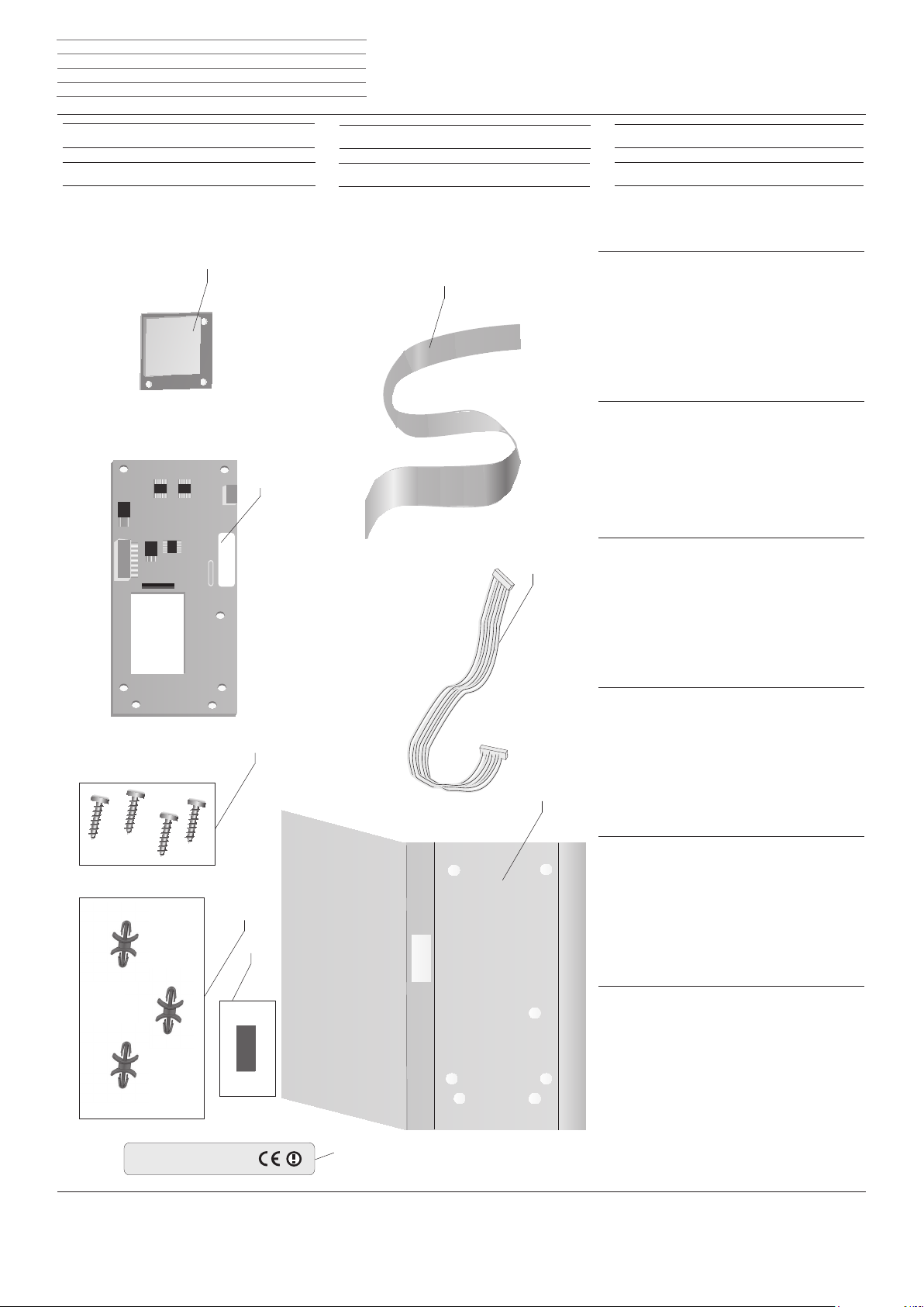
Lieferumfang
Inhoud van de levering
d
l
Dotazione
Contenu de la livraison
i
f
Scope of delivery
Volumen de suministro
g
e
d
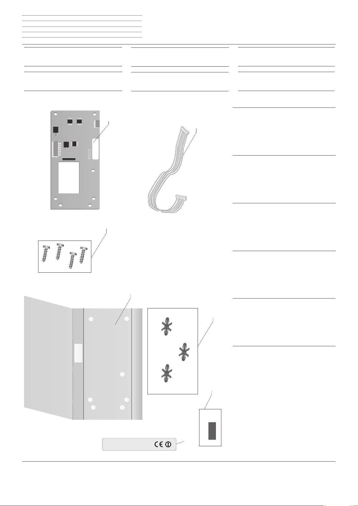
A Funk-Modul (kleine Leiterplatte)
A
B
B Flachbandkabel
C Adapter-Modul (große Leiterplatte)
D Kabelbaum 9 Pol.
E TORX Schrauben 4 Stück
F Unterlage Isolierung
G Abstandhalter 3 Stück
H Klebeetikett zum Verschließen von Position F
I Kennzeichnungsaufkleber FUNK
i
A Modulo radio (scheda elettronica piccola)
B Nastro piatto
C Modulo adattatore (scheda elettronica grande)
D Fascio di cavi 9 poli
E Viti TORX 4 pezzi
F Base di appoggio isolante
C
G Distanziale 3 pezzi
H Etichetta adesiva per chiudere la posizione F
I Etichetta FUNK
g
A Wireless module (small circuit board)
B Ribbon cable
D
C Adapter module (large circuit board)
D 9-pole cable harness
E TORX screws x 4
F Base insulation
G Spacer x 3
H Adhesive label for closing position F
I Marking sticker WIRELESS
A Radiomodule (kleine printplaat)
B Lintkabel
C Adaptermodule (grote printplaat)
D Kabelbundel 9-pol.
E
F
E TORX-schroeven 4 stuks
F Ondergrond/isolatie
G Afstandhouder 3 stuks
H Kleefetiket voor het sluiten van positie F
I Gegevenssticker FUNK
f
l
A Module radio (petite plaque conducteur)
B Câble plat
C Module adaptateur (grande plaque conducteur)
D Faisceau de câbles 9 pôl.
E Vis TORX 4 pièces
F Support isolation
G
H
G Entretoise 3 pièces
H Etiquette à coller pour le blocage de la position F
I Autocollant de marquage FUNK
e
Módulo de radiofrecuencia (placa de circuito impreso
A
pequeña)
B Cable de cinta plana
C Módulo adaptador (placa de circuito impreso grande)
D Mazo de cables 9 pol.
E Tornillos TORX 4 piezas
F Aislamiento de base
G Soporte distanciador 3 piezas
H Etiqueta adhesiva para el cierre de la posición F
I Pegatina identicativa RADIO
indoor use only
I
Page 6
Module Wireless Audio Link - 6 -
n
Einbauanweisung Inbouwinstructies
Istruzioni di montaggio Instructions de montage
Installation instructions Instrucciones de montaje
Subwoofer,
Art. Nr. 69211T10/U10/W10
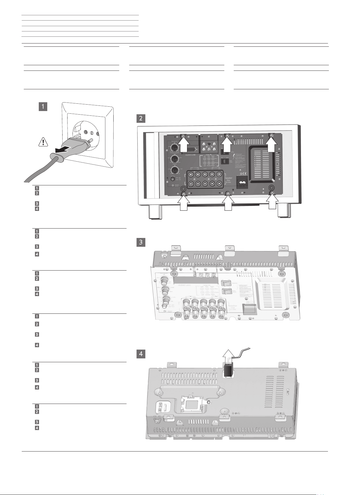
Gerät öffnen
Subwoofer,
artikelnr. 69211T10/U10/W10
Toestel openen
1
1
Netzstecker ziehen
2
Die hier mit Pfeil markierten 6 Schrauben lösen
3
Verstärker-Modul nach vorne herausnehmen
4
Zweiadrige Lautsprecherleitung (rot/ blau)
vom Verstärker-Modul lösen (Stecker entrie-
geln und abziehen)
1
Slare il connettore di rete
2
Allentare le 6 viti indicate dalla freccia
3
Estrarre il modulo amplicatore dal davanti
Staccare il cavo a due li (rosso/blu) degli altop
4
arlanti dal modulo amplicatore
(sbloccare e staccare il connettore)
1
Pull out the mains plug
2
Loosen the 6 screws marked here with an
arrow
3
Remove amplier module to the front
4
Remove two-wire speaker cable (red/ blue)
from the amplier module (unlock plug
and pull out)
1
Trek de netstekker uit het stopcontact
Draai de hier met pijlen aangeduide 6
2
schroeven los
Neem de versterkermodule er naar voren
3
toe uit
Tweedraadse luidsprekerkabel (rood/blauw)
4
an de versterkermodule loskoppelen
(stekker ontgrendelen en uittrekken)
1
Retirer la che réseau
2
Desserrer les 6 vis marquées d’une èche
d
l
Subwoofer,
Art. N. 69211T10/U10/W10
Apertura dell‘apparecchio
Subwoofer,
réf. 69211T10/U10/W10
Ouvrir l’appareil
2
d
i
3
g
l
4
f
i
f
Subwoofer,
Art. No. 69211T10/U10/W10
Opening the unit
Subwoofer,
n.º ref. 69211T10/U10/W10
Abrir el aparato
g
e
3
Extraire le module amplicateur vers l’avant
Ligne haut-parleur bicanal (rouge / bleu)
4
Débrancher du module amplicateur
(déverrouiller le connecteur et l’extraire)
1
Extraer el enchufe de red
2
Soltar los 6 tornillos marcados aquí con una
echa
3
Sacar el módulo amplicador hacia delante
4
Extraer el cable de altavoz bilar (rojo/ azul)
del módulo del amplicador (desbloquear
y retirar el conector)
e
Page 7
Module Wireless Audio Link - 7 -
n
Einbauanweisung Inbouwinstructies
Istruzioni di montaggio Instructions de montage
Installation instructions Instrucciones de montaje
Subwoofer,
Art. Nr. 69211T10/U1/W10
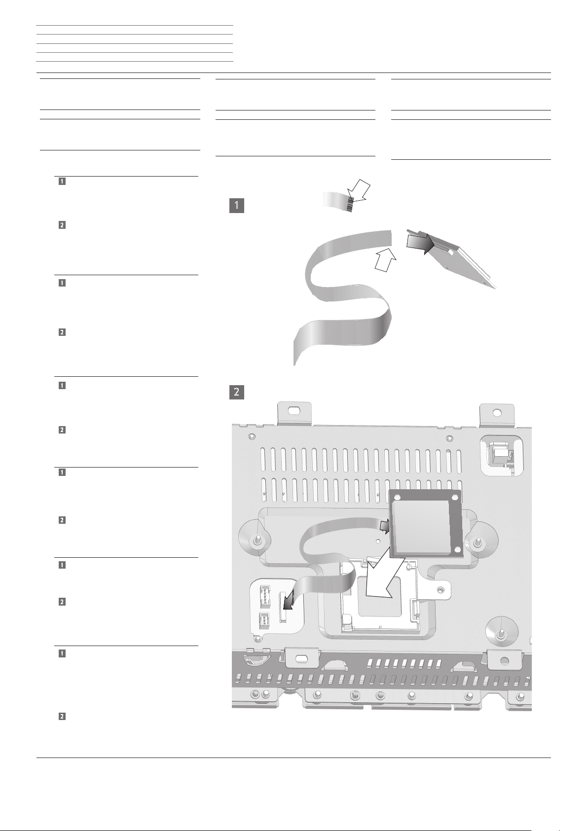
Funk-Modul montieren
Subwoofer,
artikelnr. 69211T10/U10/W10
Radiomodule monteren
1
Freie Kontaktäche (Pfeil K) am Flachbandkabel beachten.
Das Flachbandkabel in die Buchsenleiste am
Funk-Modul einstecken.
Nötigenfalls Entriegelung drücken.
2
Funk-Modul in die Halterung am Verstärker-
Modul einlegen und einrasten.
Flachbandkabel am Verstärker-Modul
anschließen (in Stecker einstecken).
Prestare attenzione alla supercie di contatto
1
libera indicata dalla freccia K sul cavo
a nastro piatto
Inserire il cavo a nastro piatto nella morsettie-
ra del modulo radio
(se necessario, premere l’elemento di sblocco)
Posare e inserire il modulo radio nel supporto
2
del modulo amplicatore
Collegare il cavo a nastro piatto al modulo
amplicatore (inserire nel connettore)
d
l
d
i
Subwoofer,
Art. N. 69211T10/U10/W10
Montaggio del modulo radio
Subwoofer, réf. 69211T10/U10/W10
Monter le module radio
1
i
f
K
Subwoofer,
Art. No. 69211T10/U10/W10
Installing the wireless module
Subwoofer,
n.º ref. 69211T10/U10/W10
Montar el módulo de radiofrecuencia
K
g
e
Take note of the free contact area arrow K on
1
the ribbon cable
Insert the ribbon cable into the socket strip on
the wireless module
(If need be, press unlock)
Place wireless module in the holder on the
2
amplier module and latch into place
Connect ribbon cable to the amplier module
(insert into plug)
1
Let op het vrije contactvlak pijl K op de lint-
kabel
Steek de lintkabel in de aansluitbalk van de
radiomodule
(indien nodig ontgrendeling indrukken)
Leg de radiomodule in de houder op de
2
versterker- module en klik ze vast
Sluit de lintkabel aan op de versterkermodule
(in de stekker steken)
Attention à la surface de contact libre (èche
1
K) du câble plat
Insérer le câble plat dans la réglette à prises
femelles du module radio
(si nécessaire, appuyer sur le déverrouillage)
Placer et enclencher le module radio dans le
2
support du
module amplicateur.
Raccorder le câble plat au module
amplicateur (brancher dans la che)
Tener en cuenta la supercie de contacto libre
1
marcada con la echa K del cable de
cinta plana
Introducir el cable de cinta plana en la regleta
de conexiones
del módulo de radiofrecuencia
(presionar el bloqueo de emergencia)
Colocar el módulo de radiofrecuencia en el
2
soporte del módulo amplicador y encajarlo
Conectar el cable de cinta plana en el módu
lo amplicador (conectar en enchufe)
g
2
l
f
e
Page 8
Module Wireless Audio Link - 8 -
L
n
Einbauanweisung Inbouwinstructies
Istruzioni di montaggio Instructions de montage
Installation instructions Instrucciones de montaje
Subwoofer,
Art. Nr. 69211T10/U10/W10
Subwoofer,
artikelnr. 69211T10/U10/W10
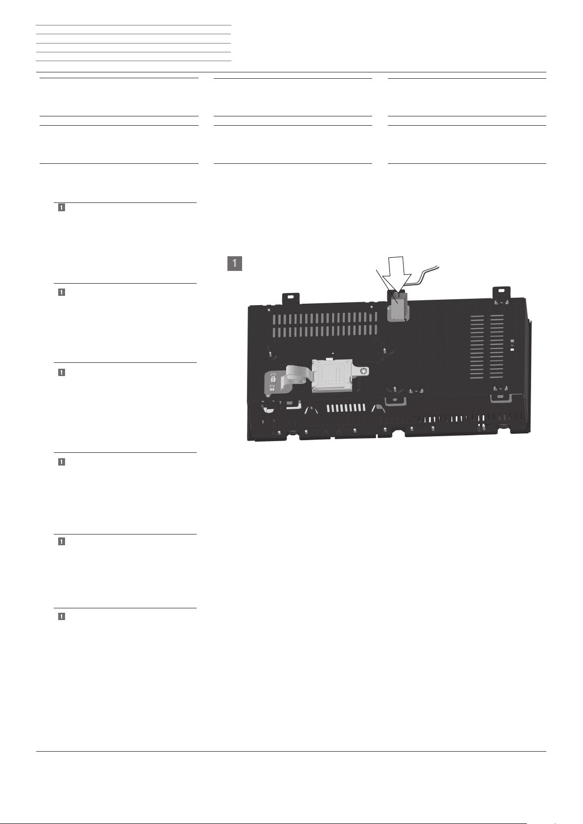
1
Verstärker-Modul mit montierten Funk-Modul.
Lautsprecherkabel L (rot/ blau) am
Verstärker-Modul wieder anschließen
Modulo amplicatore con il modulo radio
1
montato.
Collegare nuovamente il cavo altoparlante L
(rosso/blu) al modulo amplicatore
Amplier module with installed wireless
1
module.
d
l
d
i
g
Subwoofer,
Art. N. 69211T10/U10/W10
Subwoofer,
réf. 69211T10/U10/W10
1
i
f
Subwoofer,
Art. No. 69211T10/U10/W10
Subwoofer,
n.º ref. 69211T10/U10/W10
g
e
Connect speaker cable L (red/ blue) to the
amplier module again
Versterkermodule met gemonteerde radio
1
module.
Sluit de luidsprekerkabel L (rood/blauw)
opnieuw aan op de versterkermodule
Module amplicateur avec module radio
1
monté.
Raccorder le câble de haut-parleur L (rouge /
bleu) au module amplicateur
Módulo amplicador con módulo de radiofre-
1
cuencia montado.
Volver a conectar el cable de altavoz L (rojo/
azul) en
el módulo amplicador
l
f
e
Page 9
Module Wireless Audio Link - 9 -
n
Einbauanweisung Inbouwinstructies
Istruzioni di montaggio Instructions de montage
Installation instructions Instrucciones de montaje
Subwoofer,
Art. Nr. 69211T10/U10/W10
Gerät schließen
Subwoofer,
artikelnr. 69211T10/U10/W10
Toestel aansluiten
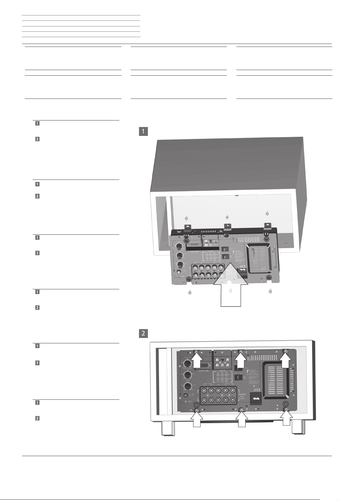
1
Verstärker-Modul wieder in das Gehaüse
einsetzen.
2
Mit den vorher entfernten 6 Schrauben das
Verstärker-Modul befestigen (Schrauben nur
handfest anziehen).
Kabel wieder anschließen.
Funktions- und Sicherheitsprüfung nach
VDE 0701 durchführen.
Inserire nuovamente il modulo amplicatore
1
nell' alloggiamento
2
Fissare con le 6 viti precedentemente rimosse
il modulo amplicatore (serrare le viti
solo a mano)
Collegare nuovamente i cavi
Eseguire la prova di funzionamento e sicurezza secondo le indicazioni VDE 0701
d
l
d
i
Subwoofer,
Art. N. 69211T10/U10/W10
Collegamento dell’apparecchio
Subwoofer,
réf. 69211T10/U10/W10
Refermer l’appareil
1
i
f
Subwoofer,
Art. No. 69211T10/U10/W10
Closing the unit
Subwoofer,
n.º ref. 69211T10/U10/W10
Cerrar el aparato
g
e
1
Place amplier module back into the
housing
2
Use the 6 screws previously removed to
fasten the amplier module (only tighten
screws hand-tight)
Reconnect cable
Perform function and safety test as per
VDE 0701
1
Breng de versterkermodule opnieuw aan
in de behuizing
2
Bevestig de versterkermodule met de eerder
verwijderde 6 schroeven (schroeven slechts
handvast aandraaien)
Sluit de kabels opnieuw aan
Werkings- en veiligheidstest volgens
VDE 0701 uitvoeren
1
Replacer le module amplicateur dans le
boîtier
Avec les 6 vis que vous avez enlevées précé-
2
demment,
xer le module amplicateur (serrer les vis
à la main uniquement)
Raccorder le câble
Exécuter un contrôle de fonctionnement et
de sécurité selon VDE 0701
1
Colocar el módulo amplicador de nuevo en
la carcasa
g
l
2
f
e
2
Fijar el módulo amplicador con los 6 tornillos
que se retiraron antes (apretar los tornillos
solo manualmente)
Volver a conectar el cable
Realizar una prueba de seguridad y funciona-
miento conforme a VDE 0701
Page 10
Module Wireless Audio Link - 10 -
n
Einbauanweisung Inbouwinstructies
Istruzioni di montaggio Instructions de montage
Installation instructions Instrucciones de montaje
Subwoofer,
Art. Nr. 69211T10/U10/W10
Nichtbenötigte Teile
Subwoofer,
artikelnr. 69211T/U/W
Niet benodigde onderdelen
E
d
l
C
Subwoofer,
Art. N. 69211T10/U10/W10
Particolari non necessari
Subwoofer,
réf. 69211T10/U10/W10
Pièces non nécessaires
Subwoofer,
i
Art. No. 69211T10/U10/W10
Parts not required
g
Subwoofer,
f
n.º ref. 69211T/U/W
Piezas innecesarias
e
d
C Adapter-Modul (große Leiterplatte)
D Kabelbaum 9 Pol.
E TORX Schrauben 4 Stück
D
F Unterlage Isolierung
G Abstandhalter 3 Stück
H Klebeetikett zum Verschließen von Teil F
I Kennzeichnungsaufkleber FUNK
i
C Modulo adattatore (scheda elettronica grande)
D Fascio di cavi 9 poli
E Viti TORX 4 pezzi
F Base di appoggio isolante
G Distanziale 3 pezzi
Etichetta adesiva per chiudere la posizione F
H
I Etichetta FUNK
g
C Adapter module (large circuit board)
D 9-pole cable harness
E TORX screws x 4
F Base insulation
G Spacer x 3
H Adhesive label for closing position F
I Marking sticker WIRELESS
C Adaptermodule (grote printplaat)
D Kabelbundel 9-pol.
E TORX-schroeven 4 stuks
F Ondergrond/isolatie
G Afstandhouder 3 stuks
Kleefetiket voor het sluiten van positie F
H
I Gegevenssticker FUNK
F
G
C Module adaptateur (grande plaque conducteur)
D Faisceau de câbles 9 pôl.
E Vis TORX 4 pièces
F Support isolation
G Entretoise 3 pièces
Etiquette à coller pour le blocage de la position F
H
I Autocollant de marquage FUNK
f
e
C Módulo adaptador (placa de circuito impreso grande)
D Mazo de cables 9 pol.
E Tornillos TORX 4 piezas
F Aislamiento de base
G Soporte distanciador 3 piezas
H Etiqueta adhesiva para el cierre de la posición F
I Pegatina identicativa RADIO
H
l
indoor use only
I
Page 11
Module Wireless Audio Link - 11 -
n
Einbauanweisung Inbouwinstructies
Istruzioni di montaggio Instructions de montage
Installation instructions Instrucciones de montaje
Subwoofer Compact,
Art. Nr. 50212T/U/W
Gerät öffnen
Subwoofer Compact,
artikelnr. 50212T/U/W
Toestel openen
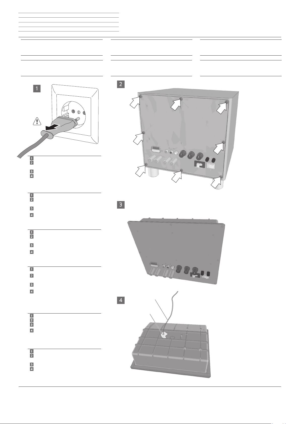
1
1
Netzstecker ziehen
2
Die hier mit Pfeil markierten 8 Schrauben
lösen
3
Verstärker-Modul nach vorne herausnehmen
4
Lautsprecherleitung K1 (rot/ blau) vom
Lautsprecher lösen.
Die Abdichtung KD nicht zerstören
1
Slare il connettore di rete
2
Allentare le 8 viti indicate dalla freccia
3
Estrarre il modulo amplicatore dal davanti
Staccare il cavo altoparlante K1 (rosso/blu)
4
dall' altoparlante
Non danneggiare la guarnizione KD
1
Pull out the mains plug
2
Loosen the 8 screws marked here with an
arrow
3
Remove amplier module to the front
Remove speaker cable K1 (red/ blue) from
4
the speaker
Do not destroy the seal KD
1
Trek de netstekker uit het stopcontact
Draai de hier met pijlen aangeduide 8
2
schroeven los
Neem de versterkermodule er naar voren
3
toe uit
4
Maak de luidsprekerkabel K1 (rood/blauw)
los van de luidspreker
Let erop dat de afdichting KD niet be-
schadigd wordt
1
Retirer la che réseau
2
Desserrer les 8 vis marquées d’une èche
3
Extraire le module amplicateur vers l’avant
Débrancher la ligne du haut-parleur K1
4
(rouge / bleu) du haut-parleur haut-parleur
Ne pas détruire la garniture d’étanchéité KD
d
l
d
i
g
l
f
Subwoofer Compact,
Art. N. 50212T/U/W
Apertura dell’apparecchio
Subwoofer Compact,
réf. 50212T/U/W
uvrir l’appareil
2
3
4
K
K D
i
f
Subwoofer Compact,
Art. No. 50212T/U/W
Opening the unit
Subwoofer Compact,
Nº ref. 50212T/U/W
Abrir el aparato
g
e
1
Extraer el enchufe de red
2
Soltar los 8 tornillos marcados aquí con una
echa
3
Sacar el módulo amplicador hacia delante
4
Soltar el cable del altavoz K1 (rojo/azul)
del altavoz
No dañar la junta KD
e
Page 12
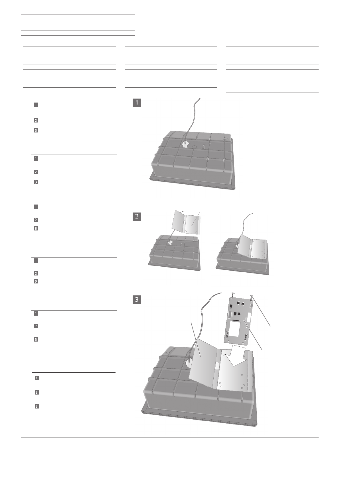
Module Wireless Audio Link - 12 -
F
n
Einbauanweisung Inbouwinstructies
Istruzioni di montaggio Instructions de montage
Installation instructions Instrucciones de montaje
Subwoofer Compact,
Art. Nr. 50212T/U/W
Funk-Modul montieren
Subwoofer Compact,
artikelnr. 50212T/U/W
Radiomodule monteren
1
Verstärker-Modul auf eine weiche Unterlage
legen
2
Unterlage/Isolierung F über die Haltedome
des Verstärker-Moduls legen
3
Adapter-Modul C in die Unterlage/
Isolierung F einlegen und mit 4 TORX-
Schrauben E befestigen.
Schrauben nur handfest anziehen
Appoggiare il modulo amplicatore su un
1
supporto morbido
Posare la base di appoggio/isolante F sulla
2
piastra di ssaggio del modulo amplicatore
Posare il modulo adattatore C nella base di
3
appoggio/ isolante F e serrare con 4 viti
TORX E
Serrare le viti solo manualmente
1
Place amplier module on a soft base
d
l
d
i
g
Subwoofer Compact,
Art. N. 50212T/U/W
Montaggio del modulo radio
Subwoofer Compact,
réf. 50212T/U/W
Monter le module radio
1
i
f
Subwoofer Compact,
Art. No. 50212T/U/W
Installing the wireless module
Subwoofer Compact,
Nº ref. 50212T/U/W
Montar el módulo de radiofrecuencia
g
e
Place base/insulation F over the holding
2
dome of the amplier module
3
Place adapter module C into the base/
insulation F and fasten with 4 TORX
screws E
Only tighten screws hand-tight.
1
Leg de versterkermodule op een zachte
ondergrond
Leg de ondergrond/isolatie F over de beves
2
tigingsnokjes van de versterkermodule
3
Leg de adaptermodule C in de ondergrond/
isolatie F en bevestig ze met 4 TORX-
schroeven E
Draai de schroeven slechts handvast aan
1
Placer le module amplicateur sur un support
souple
Placer le support / l’isolation F sur le dispositif
2
de xation du module amplicateur
3
Poser le module adaptateur C dans le support /
l’isolation F et le xer avec 4 vis TORX E
Visser les vis à la main uniquement
Colocar el módulo amplicador sobre una
1
base blanda
2
l
3
f
F
E
C
e
Colocar el aislamiento de la base F sobre los
2
ganchos del módulo amplicador
Colocar el módulo adaptador C en el aisla
3
miento/ la
base F y jarlo con 4 tornillos TORX E
Apretar los tornillos solo manualmente
Page 13
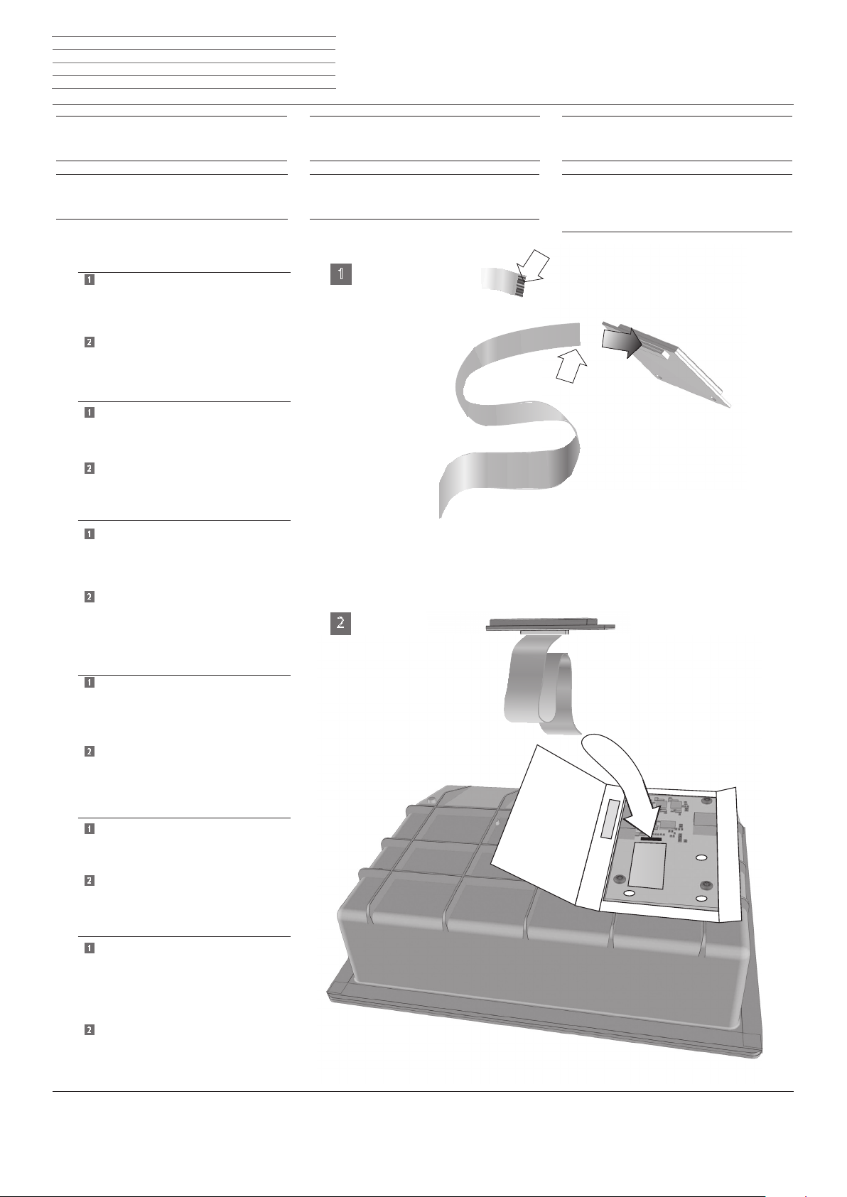
Module Wireless Audio Link - 13 -
n
Einbauanweisung Inbouwinstructies
Istruzioni di montaggio Instructions de montage
Installation instructions Instrucciones de montaje
Subwoofer Compact,
Art. Nr. 50212T/U/W
Funk-Modul montieren
Subwoofer Compact,
artikelnr. 50212T/U/W
Radiomodule monteren
1
Freie Kontaktäche (Pfeil K) am Flachbandkabel beachten.
Das Flachbandkabel in die Buchsenleiste am
Funk-Modul einstecken (Entriegelung drücken)
2
Das anderes Ende des Flachbandkabels in die
Buchsenleiste am Adapter-Modul einstecken
(siehe Pfeil)
Prestare attenzione alla supercie di contatto
1
libera indicata dalla freccia K sul cavo
a nastro piatto
Inserire il cavo a nastro piatto nella morsettiera
del modulo radio
Inserire l'altra estremità del cavo a nastro piatto
2
nella
morsettiera del modulo adattatore
(vedi freccia)
Take note of the free contact area arrow K on
1
the ribbon cable
Insert the ribbon cable into the socket strip on
the wireless module
d
l
d
i
g
Subwoofer Compact,
Art. N. 50212T/U/W
Montaggio del modulo radio
Subwoofer Compact,
réf. 50212T/U/W
Monter le module radio
1
i
f
Subwoofer Compact,
Art. No. 50212T/U/W
Installing the wireless module
Subwoofer Compact,
Nº ref. 50212T/U/W
Montar el módulo de radiofrecuencia
K
K
g
e
Insert the other end of the ribbon cable into
2
the
socket strip on the adapter module
(see arrow)
1
Let op het vrije contactvlak pijl K op de lint-
kabel
Steek de lintkabel in de aansluitbalk van de
radiomodule
(indien nodig ontgrendeling indrukken)
2
Steek het andere uiteinde van de lintkabel in de
aansluitbalk op de adaptermodule (zie pijl)
Attention à la surface de contact libre (èche
1
K) du câble plat
Insérer le câble plat dans la réglette à prises
femelles du module radio
(si nécessaire, appuyer sur le déverrouillage)
2
Encher l’autre extrémité du câble plat dans
la réglette à prises femelles du module adapta-
teur (voir èche)
Tener en cuenta la supercie de contacto libre
1
marcada con la echa K del cable de
cinta plana
Introducir el cable de cinta plana en la regleta
de conexiones
del módulo de radiofrecuencia
(presionar el bloqueo de emergencia)
Enchufar el otro extremo del cable de cinta
2
plana en la
regleta de conexiones del módulo adaptador
(ver echa)
2
l
f
e
Page 14
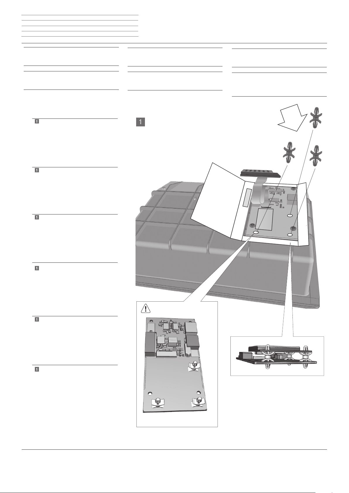
Module Wireless Audio Link - 14 -
n
Einbauanweisung Inbouwinstructies
Istruzioni di montaggio Instructions de montage
Installation instructions Instrucciones de montaje
Subwoofer Compact,
Art. Nr. 50212T/U/W
Funk-Modul montieren
Subwoofer Compact,
artikelnr. 50212T/U/W
Radiomodule monteren
1
Abstandhalter in die Bohrungen der
Leiterplatte Adapter-Modul einstecken.
Achten Sie darauf, dass die Abstandhalter
in die Bohrungen einrasten.
Funk-Modul auf die montierten Abstand-
halter aufstecken
1
Inserire i distanziali nei fori della
scheda elettronica del modulo adattatore
Accertarsi che i distanziali
si inseriscano nei fori
Collegare il modulo radio ai distanziali
montati
1
Insert spacers into the bore holes of the
adapter module circuit board
Make sure that the spacers
latch into the bore holes
Place wireless module onto the mounted
spacers
d
l
d
i
g
Subwoofer Compact,
Art. N. 50212T/U/W
Montare il modulo radio
Subwoofer Compact,
réf. 50212T/U/W
Monter le module radio
1
i
f
Subwoofer Compact,
Art. No. 50212T/U/W
Installing the wireless module
Subwoofer Compact,
Nº ref. 50212T/U/W
Montar el módulo de radiofrecuencia
g
e
Steek de afstandhouders in de boringen van
1
de printplaatadaptermodule
Let erop dat de afstandhouders in de
boringen vastklikken
Steek de radiomodule op de gemonteerde
afstandhouders
1
Encher l’entretoise dans les orices de la
plaque conducteur du module adaptateur
Veillez à ce que les entretoises
s’enclenchent dans les orices
Encher le module radio sur
les entretoises montées
Encajar el soporte distanciador en los oricios
1
de la
placa de circuito impreso del módulo
adaptador
Asegurarse de que el soporte distanciador
encaje en los oricios
Introducir el módulo de radiofrecuencia en el
soporte distanciador montado
l
f
e
Page 15
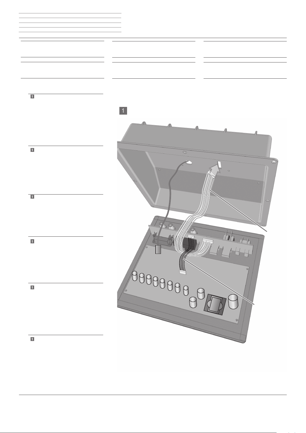
Module Wireless Audio Link - 15 -
D
V
n
Einbauanweisung Inbouwinstructies
Istruzioni di montaggio Instructions de montage
Installation instructions Instrucciones de montaje
Subwoofer Compact,
Art. Nr. 50212T/U/W
Kabelbaum 9 pol.
Subwoofer Compact,
artikelnr. 50212T/U/W
Kabelbundel 9 pol.
1
Kabelbaum 9 pol. an Stiftleiste anschließen.
Kabelbaum D hinter dem bereits am Modul
bendllichen Kabel V vorbei führen,
anschließend den noch freien Stecker
des Kabelbaums 9 pol. durch den Schlitz
in der Abdeckung noch außen führen.
Gegebenenfalls Abdichtung am Schlitz
öffnen und anschließend wieder verschließen
Collegare il fascio di cavi a 9 poli alla mor-
1
settiera
Far passare il fascio di cavi D dietro il cavo
V già previsto sul modulo
quindi, far passare verso l'esterno il connettore ancora libero del fascio di cavi a 9 poli
attraverso la fessura del coperchio
Se necessario, aprire la guarnizione lungo la
fessura e poi chiuderla nuovamente
1
Connect 9-pole cable harness to the pin strip
d
l
d
i
g
Subwoofer Compact,
Art. Nr. 50212T/U/W
Fascio di cavi 9 poli
Subwoofer Compact,
réf. 50212T/U/W
Faisceau de câbles 9 pôl.
1
i
f
Subwoofer Compact,
Art. Nr. 50212T/U/W
9-pole cable harness
Subwoofer Compact,
Nº ref. 50212T/U/W
Mazo de cables 9 pol
g
e
Route cable harness D behind the
cable V that is already located on the module
then guide the plug that is still free of the
9-pole cable harness through the slit in the
cover to the outside
If necessary, open the seal at the slit
Kabelbundel 9 pol. op de contactstrip
1
aansluiten
Kabelbundel D achter de reeds op de module
geïnstalleerde kabel V door leiden en
vervolgens de nog vrije stekker van
de kabelbundel 9 pol. door de gleuf
in de afdekking naar buiten leiden
Eventueel de afdichting van de gleuf
openen en achteraf opnieuw sluiten
Raccorder le faisceau de câbles 9 pôl. à la
1
réglette à broches
Faire passer le harnais de câbles D derrière le
câble V qui se trouve déjà lié au module
puis faire passer le connecteur encore
disponible
du harnais de câbles 9 pôles à travers la fente
du capot, vers l'extérieur
Eventuellement, ouvrir l'étoupage de la fente
puis le refermer ultérieurement
Conectar el mazo de cables 9 pol. en la
1
regleta de conectores
Pasar el mazo de cables D por detrás del
cable V
que ya se encuentra en el módulo
A continuación, sacar el conector del mazo de
cables de 9 polos. que queda libre,
a través de la ranura en la cubierta
En caso necesario, abrir la obturación de la
ranura y volver a cerrarla posteriormente
l
f
e
Page 16
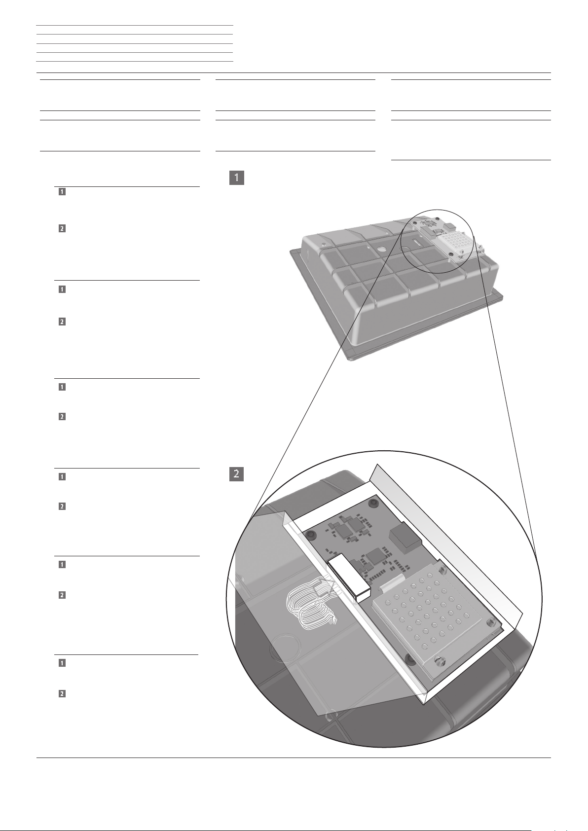
Module Wireless Audio Link - 16 -
n
Einbauanweisung Inbouwinstructies
Istruzioni di montaggio Instructions de montage
Installation instructions Instrucciones de montaje
Subwoofer Compact,
Art. Nr. 50212T/U/W
Funk-Modul anschließen
Subwoofer Compact,
artikelnr. 50212T/U/W
Radiomodule aansluiten
1
Den freien Stecker des Kabelbaums 9 pol.
durch die Öffnung in der Unterlage/ Isolation
in die Stecherleiste am Adapter-Modul
einstecken.
2
Siehe Ausschnitt, Bild 2
Unterlage / Isolation schließen und mit einem
Stück Klebeband H gegen Öffnen sichern
Far passare il connettore libero del fascio di
1
cavi a 9 poli attraverso il foro nella base di
appoggio/isolante nella morsettiera del
modulo adattatore
2
Vedere sezione, g. 2
Chiudere la base / parete isolante e con un
pezzo di nastro adesivo H assicurarla dal
rischio di apertura
d
l
d
i
Subwoofer Compact,
Art. N. 50212T/U/W
Collegamento del modulo radio
Subwoofer Compact,
réf. 50212T/U/W
Raccorder le module radio
1
i
f
Subwoofer Compact,
Art. N. 50212T/U/W
Connecting the wireless module
Subwoofer Compact,
Nº ref. 50212T/U/W
Conectar el módulo de radiofrecuencia
g
e
Insert the free plug of the 9-pole cable
1
harness through the opening in the
base/ insulation into the plug strip on the
adapter module
2
See section, image 2
Close base / insulation and secure against
opening with a strip of adhesive tape H
Steek de vrije stekker van de kabelbundel 9
1
pol. via de opening in de
ondergrond/isolatie in de aansluitbalk van
de adaptermodule einstecken
2
Zie fragment, afbeelding 2
Onderlaag / isolatie dicht doen en met een
stuk plakband H beveiligen tegen opengaan
Encher la che libre du faisceau de câbles 9
1
pôl. par l’ouverture du support / de
l’isolation de la réglette de connexion du
module adaptateur
2
Voir section, gure 2
Fermer le support / l‘isolation et empêcher
on ouverture au moyen d’un morceau de
bande collante H
Conectar el enchufe libre del mazo de cables
1
de 9 pol a través del oricio del aislamiento.
de la base en la regleta de enchufes
del módulo adaptador
2
Ver sección, gura 2
g
l
2
f
e
Cerrar la base / el aislamiento y asegurarla con
cinta adhesiva H para que no se abra
Page 17
Module Wireless Audio Link - 17 -
n
Einbauanweisung Inbouwinstructies
Istruzioni di montaggio Instructions de montage
Installation instructions Instrucciones de montaje
Subwoofer Compact,
Art. Nr. 50212T/U/W
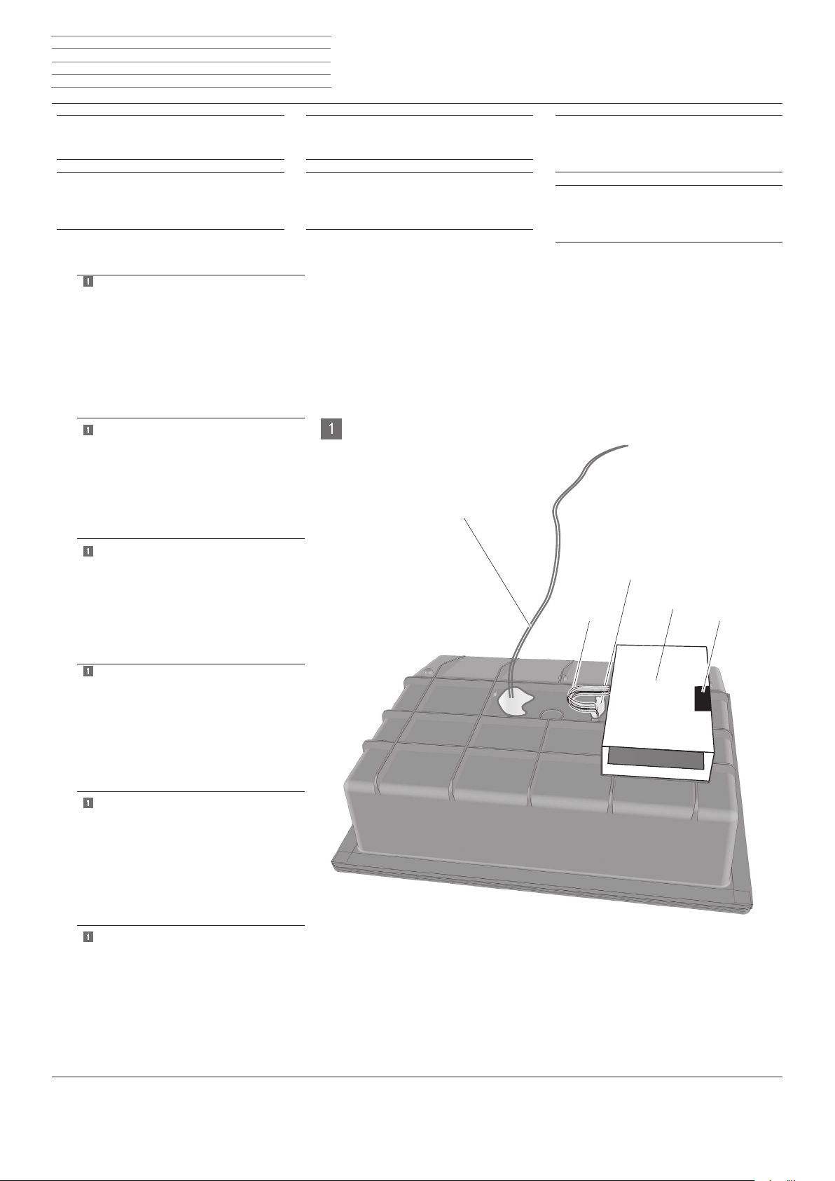
Funk-Modul fertig montieren
Subwoofer Compact,
artikelnr. 50212T/U/W
Montage van radiomodule voltooien
1
Adater-Modul und Funk-Moul in Box F
(Unterlage/ Isolation) montiert und mit
Kabelbaum 9-pol D angeschlossen.
Durchbruch KD für den Kabelbaum
wieder mit Dichtungsmittel verschlossen.
Box F (Unterlage Isolation) mit Klebeband H
verschlossen.
Lautsprecherleitung K1 (rot/ blau) wieder
am Lautsprecher anschließen.
Modulo adattatore e modulo radio montato nella
1
scatoletta F (base di appoggio/isolante)
e collegato con il fascio di cavi a 9 poli D
Fessura KD per il fascio di cavi
di nuovo chiusa con il sigillante
Scatoletta F (base di appoggio/isolante) chiusa con
nastro adesivo H
Collegare nuovamente il cavo altoparlante K1
(rosso/blu) all‘altoparlante
Adapter module and wireless module installed
1
in box F (base/ insulation) and connected to
9-pole cable harness D
Breakthrough KD for the cable harness
closed again with sealant
Box F (base insulation) sealed with adhesive tape H
Connect speaker cable K1 (red/ blue) to
the speaker again
1
Adaptermodule en radiomodule in box F
(ondergrond/isolatie) gemonteerd en met
kabelbundel 9-pol. D aangesloten
Uitsparing KD voor de kabelbundel
opnieuw gesloten met dichtingsmiddel
Box F (ondergrond/isolatie) met plakband H
gesloten
Luidsprekerkabel K1 (rood/blauw) weer
aansluiten op de luidspreker
Module adaptateur et module radio montés dans
1
le boîtier F
(support / isolation) et raccordés avec
le faisceau de câbles 9 pôl. D
Ouverture KD pour faisceau de câbles rebouchée
au moyen d’un agent d’étanchéité
Boîtier F (support / isolation) fermé avec de la
bande adhésive H
Raccorder la ligne de haut-parleur K1 (rouge / bleu)
au haut-parleur
Módulo adaptador y módulo de radiofrecuencia
1
montados en el cuadro F
(aislamiento / base ) y conectados con
mazo de cables de 9 polos D
Volver a cerrar el oricio KD para el mazo de
cables con sellador
d
l
Subwoofer Compact,
Art. N. 50212T/U/W
Montaggio nale del modulo radio
Subwoofer Compact,
réf. 50212T/U/W
Monter le module radio
d
i
1
g
l
f
e
K1
i
f
Subwoofer Compact,
Art. No. 50212T/U/W
Completing installation of the
wireless module
Subwoofer Compact,
Nº ref. 50212T/U/W
Montar el módulo de radiofrecuencia
KD
F
D
H
g
e
Tapar el cuadro F (base aislamiento) con cinta
adhesiva H
Conectar el cable del altavoz K1 (rojo/azul) de
nuevo al altavoz
Page 18
Module Wireless Audio Link - 18 -
n
Einbauanweisung Inbouwinstructies
Istruzioni di montaggio Instructions de montage
Installation instructions Instrucciones de montaje
Subwoofer Compact,
Art. Nr. 50212T/U/W
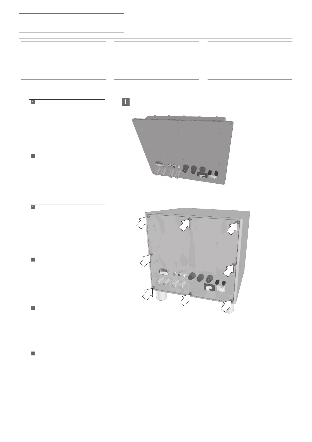
Gerät schließen
Subwoofer Compact,
artikelnr. 50212T/U/W
Toestel aansluiten
1
Gerät wieder zusammenbauen
(umgekehrte Reihenfolge wie beim Öffnen).
Modul einschieben, Schrauben (Pfeile) einschrauben.
Schrauben nur handfest festziehen.
Gerät mit externen Anschlussleitungen
verbinden.
Funktions- und Sicherheitsprüfung nach
VDE 0701 durchführen
1
Riassemblare l'apparecchio
(sequenza inversa rispetto all'apertura).
Inserire il modulo, avvitare le viti (freccia)
Serrare le viti solo a mano
Collegare l'apparecchio con i cavi di collega-
mento esterni
Eseguire una prova di funzionamento e sicurezza secondo le indicazioni VDE 0701
d
l
d
i
Subwoofer Compact,
Art. N. 50212T/U/W
Collegamento dell‘apparecchio
Subwoofer Compact,
réf. 50212T/U/W
Refermer l’appareil
1
i
f
Subwoofer Compact,
Art. No. 50212T/U/W
Closing the unit
Subwoofer Compact,
Nº ref. 50212T/U/W
Cerrar el aparato
g
e
1
Reassemble unit
(reverse the order used to open it).
Slide in module, screw in screws (arrows)
Only tighten screws hand-tight
Connect unit with external connecting cables
Perform function and safety test as per
VDE 0701
1
Toestel opnieuw in elkaar steken
(omgekeerde volgorde als bij het openen).
Module inschuiven, schroeven (pijlen) inschroeven
Schroeven slechts handvast aandraaien
Toestel met externe aansluitkabels verbinden
Werkings- en veiligheidstest volgens
VDE 0701 uitvoeren
1
Remonter l’appareil
(refaites les étapes de l’ouverture à l’inverse).
Insérer le module, visser les vis (èches)
Serrer les vis à la main uniquement
Raccorder l’appareil avec des câbles de
raccordement externes
Exécuter un contrôle de fonctionnement et
de sécurité selon VDE 0701
1
Reensamblar el aparato
(secuencia inversa a la apertura).
Desplazar el módulo, atornillar los tornillos
(echa)
Apretar los tornillos solo manualmente
Conectar el aparato con los cables de
conexión externos
Realizar una prueba de seguridad y funciona-
miento conforme a VDE 0701
g
l
f
e
Page 19
Module Wireless Audio Link - 19 -
X
3 4 9 9 2 0 0 0
n
Einbauanweisung Inbouwinstructies
Istruzioni di montaggio Instructions de montage
Installation instructions Instrucciones de montaje
Pairing
Pairing
d
l
Pairing
Couplage
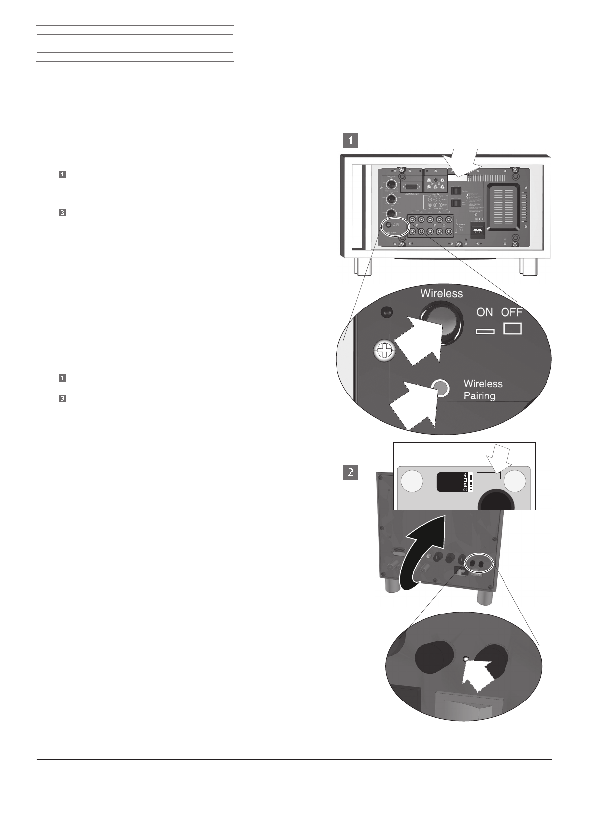
Subwoofer Art. Nr. 69211T10/ U10/ W10 und 50212T/U/W sind „Drahtlose Lautsprecher“.
Diese müssen mit dem Zuspielgerät gekoppelt werden („Pairing“ genannt).
Ausführliche Information nden Sie in der Anleitung Ihrer Wireless Audio Link Quelle.
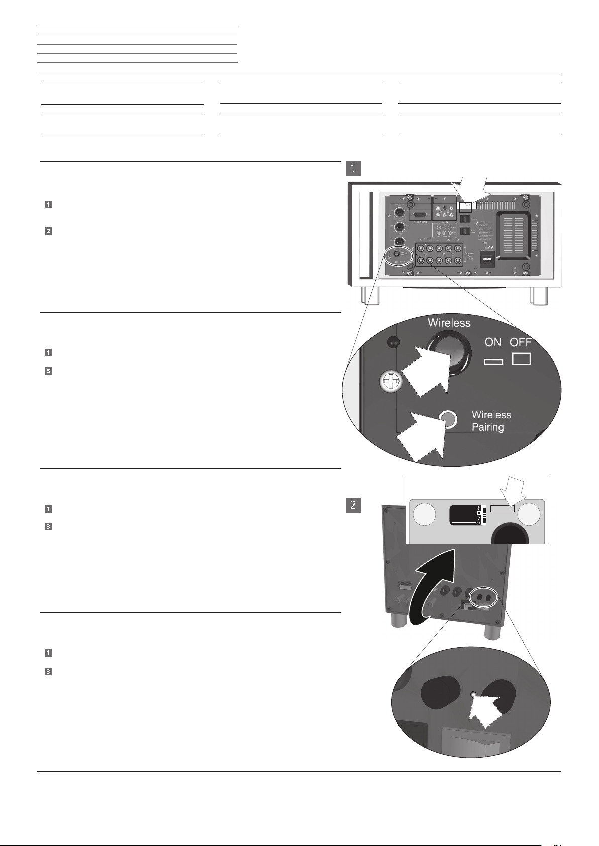
VORGEHENSWEISE für Subwoofer Art. Nr. 69211T10/ U10/ W10
1
Vor dem Anstecken die Taste „Wireless“ auf Stellung ON drücken (Skizze 1).
Nach dem Einschalten die Taste „Wireless Pairing“ mit einem Stift für ca. 1 Sekunde
drücken (Skizze 1)
2
Subwoofer Compact Art. Nr. 50212T/ U/ W: Taste im Loch (Skizze 2) ca. 1 Sekunde drücken.
Es erscheint im Menü der Quelle nach ca. 10 Sekunden der Hinweis auf einen erfolgreichen
Pairing Vorgang.
Bei Misserfolg den Abstand zwischen den beiden Geräten verringern und Subwoofer für
mehrere Sekunden vom Netz trennen, anschließend Vorgang erneut wiederholen.
Nach erfolgreicher Nachrüstung ist der Kennzeichnungsaufkleber Funk (I) an der mit X bezeichne-
ten Stelle (siehe Skizze 1 und 2) anzubringen.
I subwoofer Art. N. 69211T10/ U10/ W10 e 50212T/U/W sono "altoparlanti wireless“
Essi vanno accoppiati con l'apparecchio di riproduzione (pairing)
Informazioni dettagliate sono riportate nelle istruzioni della fonte Wireless Audio Link
PROCEDURA per il subwoofer Art. N. 69211T10/ U10/ W10
1
Prima di effettuare il collegamento, premere il tasto "Wireless" in posizione ON (disegno 1)
Premere il tasto "Wireless Pairing“ con una punta per ca. 1 secondo (disegno 1)
3
Subwoofer Compact Art. N. 50212T/ U/ W: premere il tasto nel foro (disegno 2) per ca. 1sec
Nel menu della sorgente dopo circa 10 secondi appare il messaggio che il processo di pairing è
andato a buon ne
In caso contrario, ridurre la distanza tra i due apparecchi e staccare il subwoofer per
diversi secondi dalla rete, quindi ripetere la procedura
d
i
i
f
Pairing
Pairing
g
e
1
Dopo aver completato l’aggiornamento con successo, è necessario applicare l’etichetta trasmissione (I) nel punto contrassegnato dalla X (vedere il disegno 1 e 2).
Subwoofers Art. No. 69211T10/ U10/ W10 and 50212T/U/W are "wireless speakers"
These must be paired with the source player
You can nd more detailed information in the instructions of your Wireless Audio Link source
PROCEDURE for Subwoofer Art. No. 69211T10/ U10/ W10
1
Press the "Wireless" button to the ON position before plugging in (diagram 1)
Press the "Wireless Pairing" button with a pin for approx. 1 second (diagram 1)
3
Subwoofer Compact Art. No. 50212T/ U/ W: Press button in hole (diagram 2) approx. 1 sec.
After about 10 seconds, the Source menu displays the indication that the pairing process
has been successful
If unsuccessful, reduce the gap between the two devices and disconnect the subwoofer
from the mains for several seconds, then repeat the process again
After successful retrotting, the marking sticker Wireless (I) should be afxed to the location identied by an X (see diagram 1 and 2) .
De subwoofers met artikelnrs. 69211T10/ U10/ W10 en 50212T/U/W zijn „draadloze luidsprekers“
Ze moeten worden gepaard aan het hulpapparaat (pairing)
Uitvoerige informatie vindt u in de handleiding van uw Wireless Audio Link-bron
PROCEDURE voor subwoofer artikelnr. 69211T10/ U10/ W10
1
Druk vóór het insteken de knop „Wireless“ in de stand ON (tekening 1)
Druk met behulp van een pen gedurende ca. 1 seconde op de toets „Wireless Pairing“ (tekning 1)
3
Subwoofer Compact artikelnr. 50212T/ U/ W: Druk de toets in het gat (tekening 2) ca. 1 sec. in
In het menu van de bron verschijnt na ca. 10 seconden een melding van een geslaagde pairing
Wanneer het pairen mislukt is, dient u de afstand tussen de beide toestellen te verkleinen en de
subwoofer gedurende enkele seconden los te koppelen van het net, om vervolgens de procedure
te herhalen
g
l
X
SUBWOOFER
2
Compact
Achtung: Gerät nicht öffnen - Gefahr eines elektrischen Schlags.
Reparatur nur durch Fachhandel.
Achtung: Gerät nicht öffnen - Gefahr eines elektrischen Schlags.
Reparatur nur durch Fachhandel.
Achtung: Gerät nicht öffnen - Gefahr eines elektrischen Schlags.
Reparatur nur durch Fachhandel.
Achtung: Gerät nicht öffnen - Gefahr eines elektrischen Schlags.
Reparatur nur durch Fachhandel.
Achtung: Gerät nicht öffnen - Gefahr eines elektrischen Schlags.
Reparatur nur durch Fachhandel.
Industriestraße 11
D-96317 Kronach
LOEWE.
Art.No. 50212T00 Ser.No. 00808
Nadat alle hulpstukken zijn gemonteerd moet de gegevenssticker Funk (I) op de met X gemarkeerde plaats (zie tekening 1 en 2) worden aangebracht.
Page 20
Module Wireless Audio Link - 20 -
X
3 4 9 9 2 0 0 0
n
Einbauanweisung Inbouwinstructies
Istruzioni di montaggio Instructions de montage
Installation instructions Instrucciones de montaje
Les Subwoofer réf. 69211T10/U10/W10 et 50212T/U/W sont des « haut-parleurs sans
l »
Ils doivent être couplés avec l’appareil de lecture (couplage)
Pour de plus amples informations, consulter le mode d’emploi de votre source Wireless
Audio Link
PROCÉDURE À SUIVRE pour le Subwoofer réf. 69211T10/U10/W10
1
Avant le branchement, placer le bouton « Wireless » en position ON (schéma 1)
Enfoncer le bouton « Wireless Pairing » avec un crayon pendant env. 1 seconde
(schéma 1)
Subwoofer Compact réf. 50212T/U/W : enfoncer le bouton dans le trou (schéma 2)
3
pendant env. 1 sec.
Au bout de 10 secondes environ s’afche, dans le menu de la source,
un message conrmant le succès de la procédure de Pairing
En cas d’échec, réduire la distance séparant les deux appareils et débrancher
le subwoofer du réseau pendant quelques secondes, avant de recommencer la
procédure
Lorsque vous avez terminé, collez l’autocollant de marquage Funk (I) à l’endroit marqué d’une X (voir schémas 1 et 2) .
Los subwoofer n.º ref. 69211T10/ U10/ W10 y 50212T/U/W son "Altavoces inalámbricos“
Se deben emparejar con el equipo de reproducción (denominado pairing)
Encontrará información detallada en el manual de su fuente Wireless Audio Link
PROCEDIMIENTO para el subwoofer n.º ref. 69211T/ U/ W
1
Antes de la conexión, pulsar el botón "Wireless" en la posición ON (esquema 1)
Pulsar el botón "Wireless Pairing" con un lápiz durante aprox. 1 segundo (esquema 1)
Subwoofer Compact con nº de art. 50212T/ U/ W: apretar la tecla en el oricio (cro-
3
quis 2) durante 1 seg., aprox.
Después de 10 seg., aprox., en el menú de la fuente, aparerce la indicación de un
proceso de pairing correcto
Si no se efectúa correctamente, reducir la distancia entre ambos aparatos y separar
los subwoofers de la red durante varios segundos. A continuación, repetir el proceso
f
1
e
Tras completar la modicación, hay que pegar la pegatina identicativa de radio (I) en
el lugar marcado con una X (véanse croquis 1 y 2).
X
SUBWOOFER
2
Compact
Achtung: Gerät nicht öffnen - Gefahr eines elektrischen Schlags.
Reparatur nur durch Fachhandel.
Achtung: Gerät nicht öffnen - Gefahr eines elektrischen Schlags.
Reparatur nur durch Fachhandel.
Achtung: Gerät nicht öffnen - Gefahr eines elektrischen Schlags.
Reparatur nur durch Fachhandel.
Achtung: Gerät nicht öffnen - Gefahr eines elektrischen Schlags.
Reparatur nur durch Fachhandel.
Achtung: Gerät nicht öffnen - Gefahr eines elektrischen Schlags.
Reparatur nur durch Fachhandel.
Industriestraße 11
D-96317 Kronach
LOEWE.
Art.No. 50212T00 Ser.No. 00808
Page 21

 Loading...