

Page 1
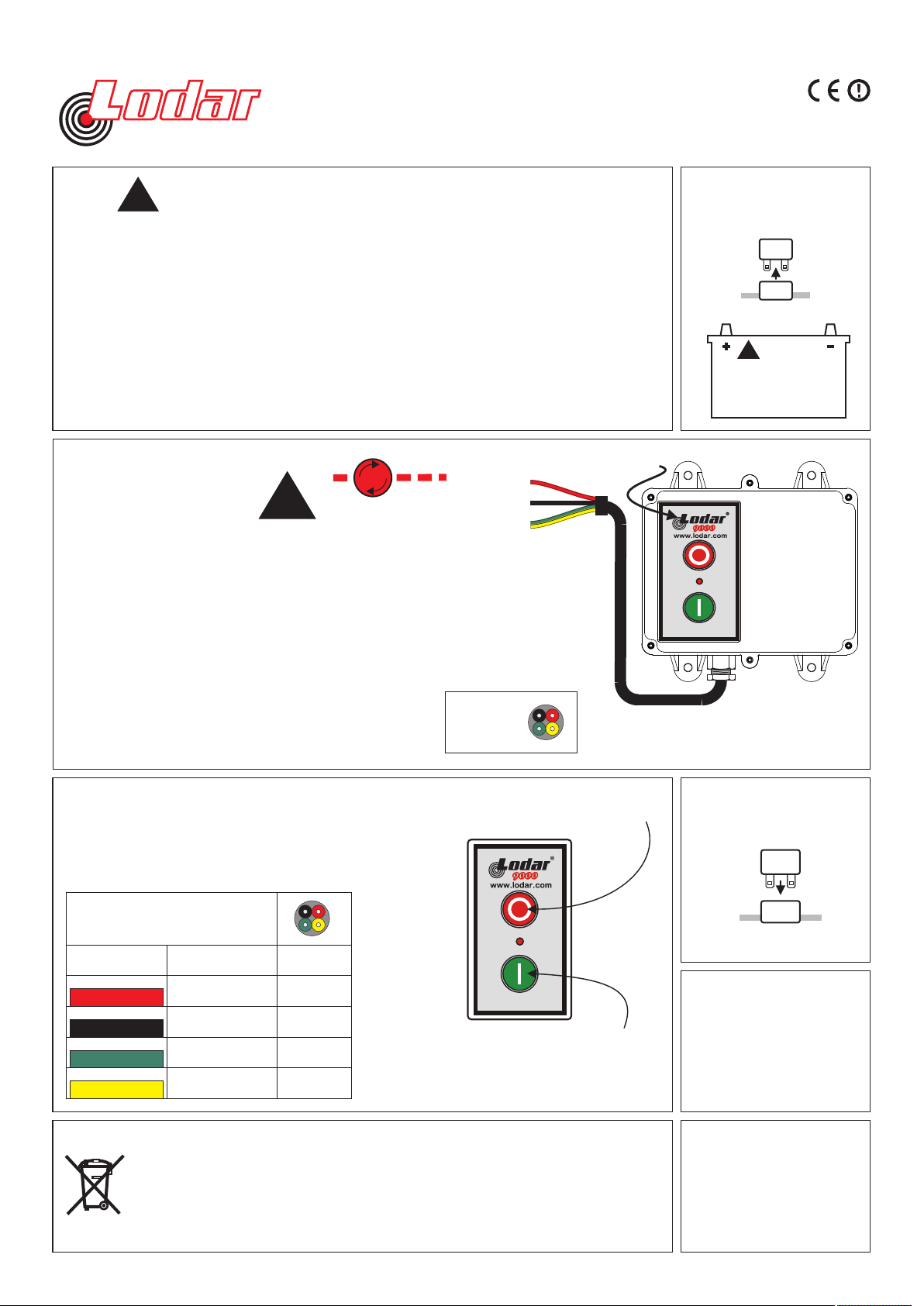
Wiring Instructions for 92 Series & 93 Series One Function Systems
BEFORE YOU START
!
1
1. The Receiver is designed to carry a maximum of 15 Amps. That is, for example,15 Amps
through one output or 5 Amps each through 3 outputs.
2. Master Output. This can be configured to Continuous or Parallel operation, see overleaf for
details.
3. If Receiver outputs are connected in parallel with an external switching device (wired remote)
the Receiver will instantly switch off when the wired remote is operated
IDENTIFY POWER
CONNECTION POINT
AND ISOLATE SUPPLY
2
Remove fuse
Fuse
or Disconnect Battery
92101.02E
4. Lodar Receivers have an isolation switch for safety, to allow for registering a MUST
replacement Transmitter.
5. Safety Feature. Both the Transmitter and the Receiver will “time out” after 30 minutes of
inactivity. This can be altered, ask your dealer.
Shown with optional Keypad
MOUNT RECEIVER
3
TAKE TIME TO LOCATE THE BEST POSITION
If necessary, power the Receiver and move it around
the vehicle until the required performance is achieved.
Operate the Transmitter and observe the Receiver
internal LED’s.
Mount as HIGH as possible
AVOID surfaces with HEAVY VIBRATION
AVOID DIRECT SPRAY from wheels
In a HOT CLIMATE fit in a SHADED position
Cable gland should face DOWN or BACK
Receiver 9206RX and 9306RX shown,
Waterproof to IP67, complete with 3 metres (10 ft) cables
CAUTION
CONNECT WIRES
!
STOP
When pressed switches F2 OFF (de-latch F2)
POSITIVE
NEGATIVE
92 00 RX
& 93 00 RX
have
4 core cable
STOP Button switches system OFF
4
Transmitter Function I.D.
!
Vehic le b atte ries con tain ga sses
which are flammable and explosive.
Wear eye protection and do not lean
over battery while disconnecting. Do
not wear metal jewellery.
Secure using 5mm (3/16") bolts (not supplied)
through the 4 mounting feet
5
WARNING
ACTIVATE SUPPLY
Replace fuse
Fuse
RECEIVER WIRES for given
Transmitter Operation
WIRE COLOUR
RED
BLACK
GREEN
YELLOW
FUNCTION
12 to 36 Volts DC
Positive
Negative
Output F1
Momentary
Output F2
Latched
Your product is marked with this symbol. It means that used electrical and electronic products
should not be mixed with general household waste. There is a separate collection system for
these products.
In the EEC - Please contact your National Distributor (see www.lodar.com for this information) who
will inform you about the take-back of the product. You might be charged for the costs arising from
the take-back and recycling. Small products might be taken back by your local collection facilities.
Outside the EEC - If you wish to discard this product please contact your local authorities and
ask for the correct method of disposal
9201
9301
YES
YES
YES
YES
SET Button switches system ON
When pressed switches
F1 ON and latches F2 ON
When released switches
F1 OFF ONLY (F2 remains ON)
or re-connect Battery
CONNECT
TRANSMITTER
6
have to be disconnected
7
BATTERY
Batteries generally
when shipping.
TEST
Press the Transmitter
button to activate RESET
the system, and carefully
test each function for
correct operation.
Page 2
FM Series - Effective working range up to a distance of 60 metres (200 feet).
Narrow Band FM Series - Effective working range up to a distance of 300 metres (1000 feet)
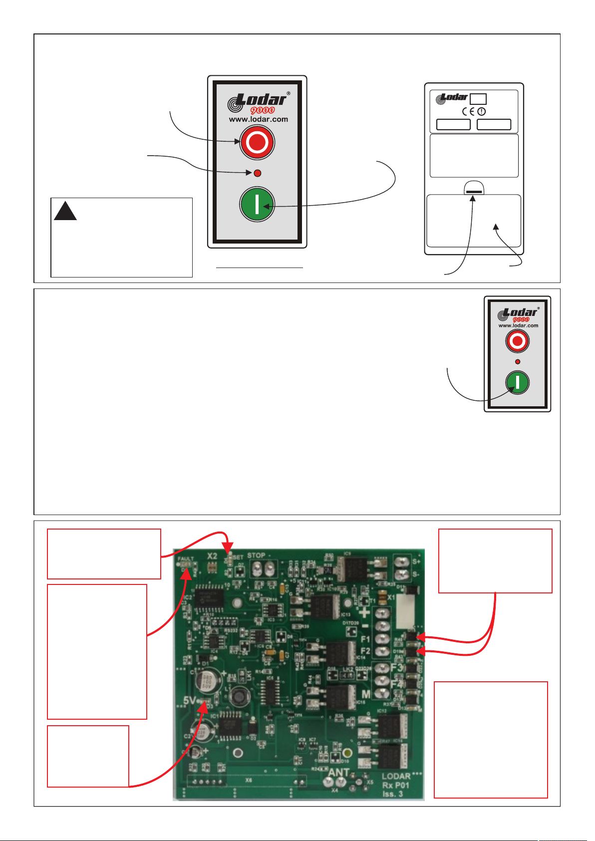
Button switches off the STOP
Receiver and the keypad function
buttons switches F2 OFF (de-latch F2)
L.E.D.
Blinks when Transmitter
and Receiver are active.
ON when a Transmitter
Button is pressed.
Pulses while transmitting
when battery is low.
SAFETY FEATURE
!
The Transmitter automatically
transmits a signal afterSTOP
30 minutes; this de-activates
the Receiver and the Transmitter
keypad.
Lo-Cover not shown
RESET Button activates
the Receiver and the
keypad function buttons
When pressed switches
F1 ON and latches F2 ON
When released switches
F1 OFF ONLY
(F2 remains ON)
Release Catch
e
www.lodar.com
Model No.
92104TX
FCC ID: M2H LODAR 8522
This devise complies with Part 15 of the FCC
Rules. Operation is subject to the following two
conditions, (1) This d evise may not ca use
harmful interference and, (2) this devise must
accept any interference received, including
int erf ere nce tha t ma y ca use und esir ed
operation.
11 023087
Serial No.
200000
Battery
Compartment
92101.02E
To register Transmitters to the Receiver.
Switch OFF or DISCONNECT the power to the Receiver and briefly PRESS the STOP button
on one or both Transmitter(s). Switch ON or Reconnect the power to the Receiver.
This opens a 20 second registration window in the Receiver processor.
If you are looking at the Receiver PCB the Fault LED Flashes. Immediately PRESS and
HOLD the Transmitter RESET Button for a MINIMUM of 5 seconds during this 20 second
window. When the Transmitter is Registered the Fault LED will be illuminated for 3 seconds.
PRESS
&
HOLD
for
10 SECONDS
at RX
POWER UP
Within this period, release the RESET button.3 second
TO REGISTER TWO TRANSMITTERS:
When the fault light starts to flash again, immediately PRESS and HOLD the Transmitter RESET
Button of the second Transmitter until the SET LED comes on. Both your Transmitters will now operate
the Receiver.
PRIORITY.
Only one Transmitter can be active at any time. For the second Transmitter to work you have to turn off the first Transmitter.
Once the second Transmitter is being used then that has priority and it has to be turned off before the first Transmitter can work
again.
If you have any problems please phone either your local Distributor or Lodar directly:UK +44 1922 613633. US 1-877- 257-1581.
LED marked “SET”
Indicates system
is active
Component Detail
LED’s marked
“F1 - F2 “
When ON indicate an
output to that function
LED marked “FAULT”
Indicates an overload is
present; the System
cannot be RESET until
overload is removed.
This LED blinks for 20
seconds when the
Receiver is initially
powered. A replacement
Transmitter has to be
registered during this 20
second period.
LED marked “5V”
Indicates power
supply for control
circuits is OK
VOLTAGE
Working Range
12 Volts to 36 Volts DC
Limits
8 Volts minimum to
40 Volts absolute max.
Note 42 Volt System
48 Volt Max is currently
Special Order
 Loading...