

Page 1
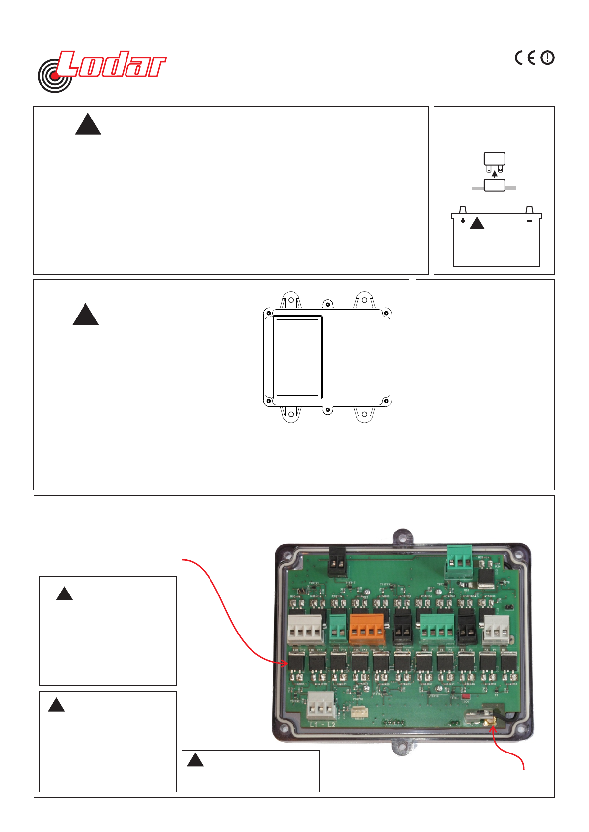
Wiring Instructions for 10, 16 & 20 Function, 92 & 93 Series, FET Receivers.
BEFORE YOU START
!
1
1. The Receiver is designed to carry a maximum of 15 Amps. That is, for example,15 Amps
through one output or 5 Amps each through 3 outputs.
2. Master Output. This can be configured to Continuous or Parallel operation, see below right
for more details.
3. If Receiver outputs are connected in parallel with an external switching device (wired remote)
the Receiver will instantly switch off when the wired remote is operated
IDENTIFY POWER
CONNECTION POINT
AND ISOLATE SUPPLY
2
Remove fuse
Fuse
or Disconnect Battery
92220RX.01E
4. Lodar Receivers have an isolation switch for safety, to allow for registering a MUST
replacement Transmitter.
5. Safety Feature. Both the Transmitter and the Receiver will “time out” after 30 minutes of
inactivity. This can be altered, ask your dealer.
MOUNT RECEIVER
3
TAKE TIME TO LO CATE THE BEST POSITION
If necessary, power the Receiver and move it around
the vehicle until the required performance is achieved.
Operate the Transmitter and observe the Receiver
internal LED’s.
Mount as HIGH as possible
AVOID surfaces with HEAVY VIBRATION
AVOID DIRECT SPRAY from wheels
In a HOT CLIMATE fit in a S HAD ED position
Cable gland should face DOWN or BACK
Receiver 92 20 RX and 93 20 RX shown,
!
CAUTION
Secure using 5mm (3/16") bolts (not supplied)
through the 4 mounting feet
!
Vehic le ba tteri es cont ain g asses
which are flammable and explosive.
Wear eye protection and do not lean
over battery while disconnecting. Do
not wear metal jewellery.
WARNING
4
What is the MASTER Output for ?
It is used to operate the pump of an
electro-hydraulic power pack or
maybe a clutch pump. It can also be
used for powering a dump valve,
master valve etc.
It can be configured to work
continuously, that is ON when SET
is pressed and OFF when STOP is
pressed;
or in
parallel with any output, that is, it is
active only a function is operated.
If it is needed with certain functions
only, this can easily be configured.
IMPORTANT
TAKE CARE NOT TO SHORT
OUT THE MOSFET’s WHEN
MAKING CONNECTIONS
IMPORTANT
!
ENSURE THAT THE GAU GE
OF WIRE USED CAN CARRY
15 AMPS (THIS IS THE
MAXIMUM TOTAL CURRENT
THAT LO DAR CAN SWITCH)
OVER THE DISTANCE FROM
THE BATTERY WITH NO
SIGNIFICANT VOLTS DR OP!
!
The STOP input can be
used for OVERLOAD or
OVER-TEMPERATURE
etc. If the chassis is
GROUND, then a return
wire is not required.
NOTE
5
!
SAFETY FEATURE
The Receiver switches itself off
after 30 minutes of inactivity.
CONNECTION DETAIL
OPTIONAL AERIAL
CONNECTION
Page 2
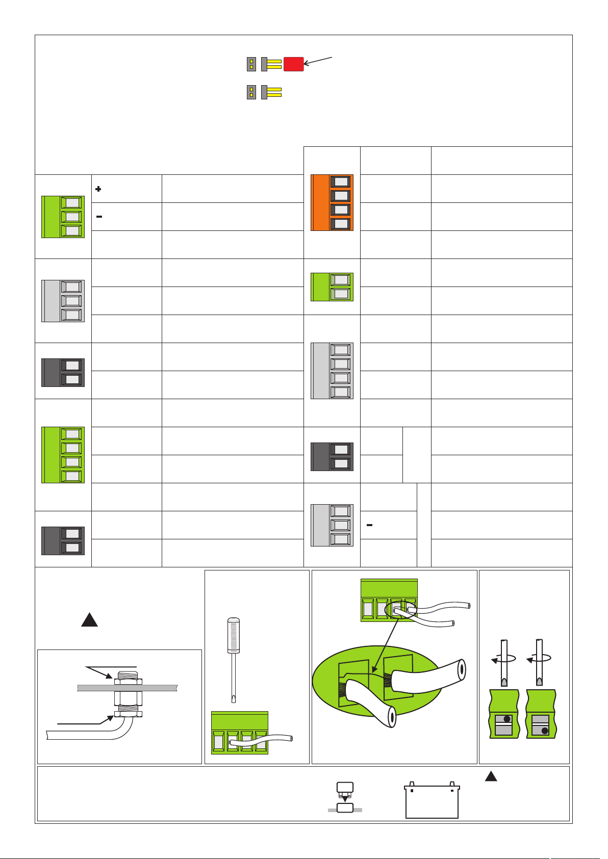
6
Make connections as detailed below
and record wire colours in the boxes
LK1
LK2
92220RX.01E
JUMPER may be or RED BLUE
LK1, when bridged causes the Master Output to be Parallel
LK2, when bridged causes the Master Output to be Continuous
JUMPER MUST BE FITTED FOR L ODAR TO WORK
POWER DOWN RECEIVER BEFOR E MAKING CHANGES
FUNCTION 11
12 / 24 VOLT
COMMON
GROUND
S+ (Safety
Solenoid etc.)
MASTER
FUNCTION 1
FUNCTION 2
FUNCTION 3
FUNCTION 4
FUNCTION 5
FUNCTION 6
FUNCTION 7
FUNCTION 12
FUNCTION 13
FUNCTION 14
FUNCTION 15
FUNCTION 16
FUNCTION 17
FUNCTION 18
FUNCTION 19
FUNCTION 20
STOP
0 Volts
STOP
Connections
FUNCTION 8
FUNCTION 9
FUNCTION 10
FINAL CHECK
7
ALL ITEMS
!
IMPORTANT
Check locknut
a
Check gland
Check tightness of cable gland
e
IT IS NOW SAFE TO RECONNECT THE POWER SUPPLY
b
Check all
connector
screws for
tightness
even the ones
that are not
used as these
could cause a
short circuit
if they vibrate
out of the
connector
L1 = LIMIT 1
GROUND
L2 = LIMIT 2
c
Stray strands of wire can
cause a short circuit
Refit fuse
Fuse
LIMIT INPUTS
or Connect Battery
SPECIAL
ORDER
ONLY
CONNECTOR
BLOCK
d
!
WARNI NG
Vehicle batteries contain gasses
w h i c h a re fl a m m a b l e a nd
explosive. Wear eye protectio n
and do not lean over battery while
secure wire
Page 3
92220RX.01E
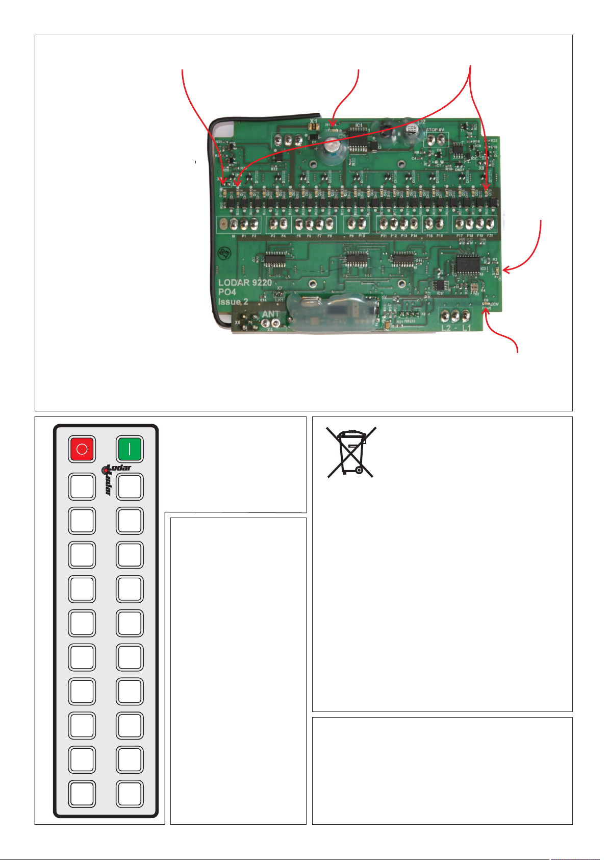
Indicator LED - Master
LED’s indicate the following
LED marked “5V” indicates
power supply for control circuits
is OK
LED marked “SET” indicates the
system active.
LED marked “Fault” indicates an
overload is present; the system
cannot be reset until overload is
removed.
This LED blinks for 20 seconds
when the system is initially
powered. A replacement
Transmitter (or Keypad or Wired
Remote) has to be registered
during this 20 second period.
5 Volts LED
Indicator LED’s 1 through 20
Set LED
LED’s marked F1 to F16 and M
(and optional MC) when ON
indicate an output to that function
(MC is an extra Continuous
Master output)
IPIP
F1
F3
F5
F7
F9
F2
F4
F6
F8
F10
F11 F12
F13
F15
F17
F14
F16
F18
F19 F20
COMPONENT DETAIL
Numbering convention
of Transmitter Keypad
showing the Receiver
output function number
for that key.
LIMITS - What are these?
The new compact 20
function Receiver has an
input for limit functions.
The circuits between L1 and
ground (-) or L2 and ground,
which when the circuit is
made, or broken, will allow
a function to start or cause
a function to stop.
This requires special
programming.
We also have available an
add-on PCB, Part No. 9220
that has a further 8 Limits.
We have successfully used
this feature on a number of
projects to introduce a
degree of logic using the
on board Programmable IC
or PIC. It may not be
economical to program the
Receiver PIC for a small
batch, please ask.
Fault LED
Your product is marked with this symbol. It means
that used electrical and electronic products should
not be mixed with general household waste. There is
a separate collection system for these products.
In the EEC - Please contact your National Distributor
(see www.lodar.com for this information) who will
inform you about the take-back of the product. You
might be charged for the costs arising from the takeback and recycling. Small products might be taken
back by your local collection facilities.
Outside the EEC - If you wish to discard this product
please contact your local authorities and ask for the
correct method of disposal
Lodar 9100 Series is guaranteed for a period of 24
months from the date of purchase, as long as it is
wired in accordance with our instructions, and that
the equipment is fitted with an isolation system to
shut off all power in event of an emergency.
 Loading...