

Page 1
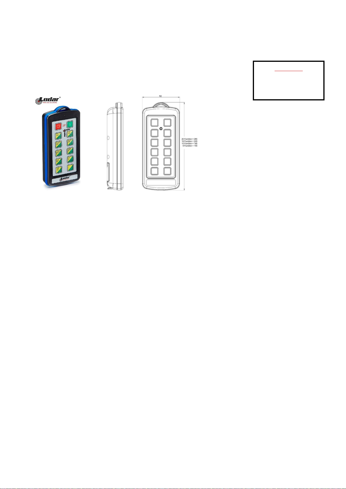
w92310TX.08
10 Function IP Extend Transmitter
REPLACEMENT TRANSMITTER
92310TX 10 Function IP Transmitter with Extend Buttons.
(20 Function in Extend Mode)
TRANSMITTER SPECIFICATION
ENCLOSURE
Material ABS
Switch Type Tactile Dome on PCB Keypad
Functions 20
Identification Pockets for printed text or image insertion
RF
Modulation 2-GFSK. Gaussian Frequency Shift Keying
Frequency 433.050 MHz to 434.790 MHz
Channels 1
Channel Selection Fixed
Technology Hand-held Transmitter
Temperature Range -10o C to + 40o C (13o F to + 104o F). Use Lithium for lower temperatures
Range 60m (200ft)
Aerial Internal – printed on PCB
Transmitted power 1mW Typical
POWER
Batteries 4 x AAA Alkaline Manganese in holder (6 Volts)
Quiescent Current 15µA
Current Transmitting 20mA
PROTECTION
IP Rating 65
Registration codes Over 16 million
INDICATOR
Type 1 x Red LED
Off Transmitter is OFF and in standby mode
Slow flash Transmitter is ON and ready for use (The SET Button has been pressed and released)
On Transmitting (A STOP, SET or Function Button is being pressed)
Fast flash Transmitting – Indication that the battery will need replacing soon
COMPLIANCE
FCC FCC CFR 47-part 15.231
433.9MHz
IC ISED RSS-210 Issue 8
433.9MHz
RoHS Directive 2011/65/EU
CONTENTS
1 x IP Extend Transmitter
1 x Lanyard
1 x Instructions
Page 2
w92310TX.08
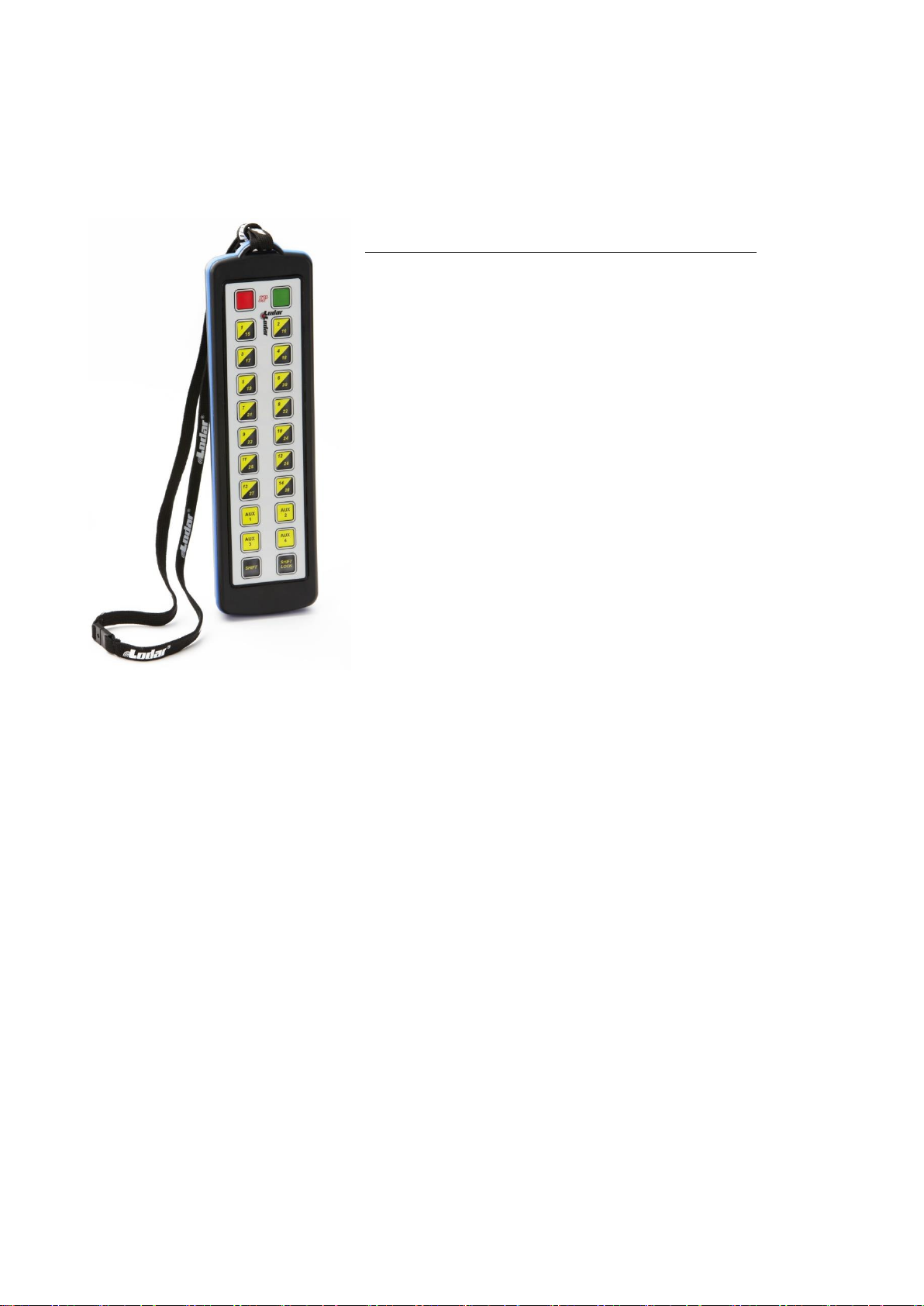
EXPLANATION OF “SHIFT” & “EXTEND” OPERATIONS - as illustrated with a 20 Function Transmitter.
These “SHIFT” operations can be applied to ALL Transmitters. For example, a 10 function Transmitter will
give 20 functions – ideal if you do not want the larger 20 function Transmitter.
To operate 2 x 20 function Receivers, giving 40 functions
This is a standard 20 function Transmitter, modified so that it
transmits 20 functions in two different modes.
The Green SET Button is the SHIFT button. Both 20 function
Receivers can therefore be operated by one Transmitter.
Press the Green SET Button to turn both Receivers on - it will start
in mode One; press it again for mode Two; press it again for mode
One, and so on.
Press the Red Stop button to turn both modes off.
Receiver One (functions 1 to 20) is operated with the SHIFT buttons
in mode One, indicated when the Keypad LED is flashing during
operation.
Receiver Two (functions 21 to 40) is operated with the SHIFT
buttons in mode Two, indicated when the Enclosure LED is flashing
during operation.
To register a Transmitter to its TWO Receivers.
Switch OFF or DISCONNECT the power to the Receivers.
Switch ON or Reconnect the power to Receiver ONE, this opens a 10 SECOND registration window in its
processor.
Immediately PRESS and HOLD the green SET button while the registration window is open until the SET LED
lights (5 seconds), the SHIFT function must NOT be active.
Receiver TWO, repeat the process but this time PRESS and HOLD the SHIFT button, and PRESS and HOLD
the SET button until its SET LED lights.
You have now coded the Transmitter to both receivers.
 Loading...