

Page 1
w92004.09
4 Function with Mini Transmitter
SYSTEM PART NUMBER
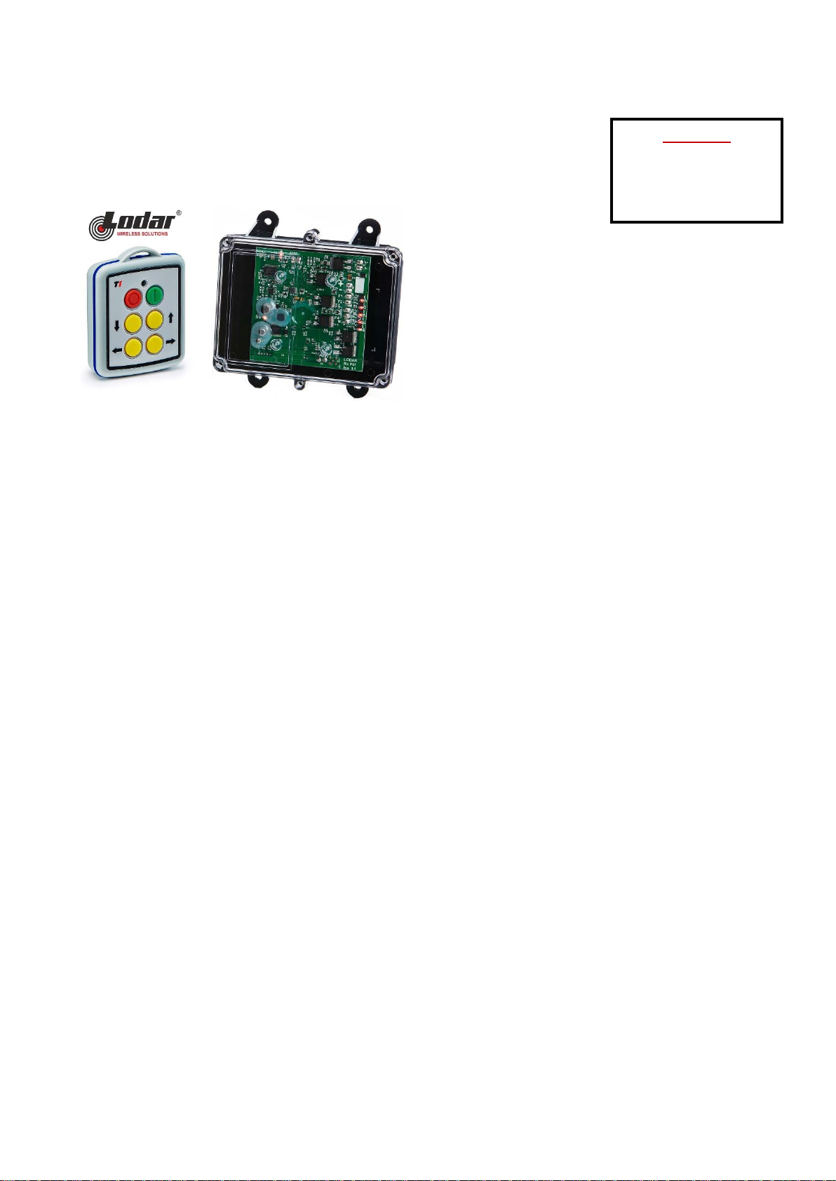
92004 4 Function Receiver with Master + 4 Function Mini Transmitter
REPLACEMENT TRANSMITTER
90004TX - 2 Function Mini Transmitter
REPLACEMENT RECEIVER
9204RX - 2 Function Standard
TRANSMITTER SPECIFICATION
ENCLOSURE
Material ABS
Switch Type Silicone Rubber keypad with carbon pill
Functions 4
Identification Subsurface printed transmitter label
RF
Modulation 2-GFSK. Gaussian Frequency Shift Keying
Frequency 433.050 MHz to 434.790 MHz
902.025 MHz– 927.975 MHz
Channels 32
Channel Selection Fixed
Channel Hopping
Technology Hand-held Transmitter
Temperature Range --10o C to + 40o C (13o F to + 104o F). Use Lithium for lower temperatures
Range 45m (150ft)
Registration Codes Over 16 million
Aerial Internal – printed on PCB
Transmitted power < 0.4mW Typical
POWER
Batteries 2 x AAA – 3 volts.
Quiescent Current 5µA
Current Standby (SET) 2mA
Current Transmitting 30mA
RF Radiated Power 0dBm
SAFETY & PROTECTION
IP Rating 65
Reverse Polarity Protection Proteted
INDICATOR
Type 1 x Red LED
Off Transmitter is OFF and in standby mode
Slow flash Transmitter is ON and ready for use (The SET Button has been pressed and released)
On Transmitting (A STOP, SET or Function Button is being pressed)
Fast flash Transmitting – Indication that the battery will need replacing soon
CONTENTS
1 x Receiver
1 x Mini Transmitter
1 x Lanyard
1 x Instructions
Page 2

w92004.09
COMPLIANCE
FCC FCC CFR 47-part 15.231
FCC CFR 47-part 15.109
433.050MHz to 434.790MHz
FCC CFR 47-part 15.249
FCC CFR 47-part 15.109
902.025MHz to 927.975MHz
IC ISED RSS-210 Issue 9
ISED RSS-GEN Issue 4
ICES-003 Issue 6.
433.050MHz to 434.790MHz
ISED RSS-210 Issue 9
ISED RSS-GEN Issue 5
ICES-003 Issue 6.
902.025MHz to 927.975MHz
RoHS Directive 2011/65/EU
RECEIVER SPECIFICATION
ELECTRICAL
Voltage Nominal 12/24V DC
Voltage Min/Max 8 to 36V DC
Switch Type MOSFET (Positive Switching)
RF
Modulation 2-GFSK. Gaussian Frequency Shift Keying
Frequency 433.050 MHz to 434.790 MHz
902.025 MHz– 927.975 MHz
Channels 32
Channel Selection Fixed
Channel hopping
Technology Fixed Receiver
Temperature Range -40o C to + 70o C (-40o F to + 158o F)
Range 60m (200ft)
CURRENT CAPACITY
FET Rating 10A
System Rating 10A
Quiescent Current 31mA 12V/ 17mA 24V on Standby (Not SET)
Overload Protection 10A (Auto Shutdown)
AERIAL
Internal Antenna Yes Supplied and fitted
External Antenna Optional AC9860/ AC9861/ AC9862/ AC9863 & AC9869 – order separately
OUTPUTS
Master Yes
Function 4 Supply to Receiver is switched
CONFIGURATION
RS232 Programming Yes For programming interlocks, push/push latch, parallel master inhibit, timeout, channel timeout delay,
to users’ requirements master on delay, radio button de-latching and output allocation.
PERFORMANCE
Simultaneous Outputs Yes Programable (Modify through configuration)
Instant TX response Yes Programable (Modify through configuration)
DIAGNOSTICS
LED’s Yes Confirm 5 Volts, SET, Fault and all Outputs.
PROTECTION
Back EMF Yes Diode protection on all outputs
Registration codes Yes Over 16 million
STOP Connection Yes Internal Emergency Stop Connection
WIRING
Wiring Loom Yes 3 metres (10ft) supplied and fitted
Cable Gland Yes Supplied and fitted
Connections Screw terminal into plug and socket on PCB, for easy “swap out”
Page 3
w92004.09
ENCLOSURE
Weight 0.3 lbs (335gms)
Lid Clear PC/FR V0 and UV stabilised
Base Black PC V0 and UV stabilised
Breather Gortex fitted in base
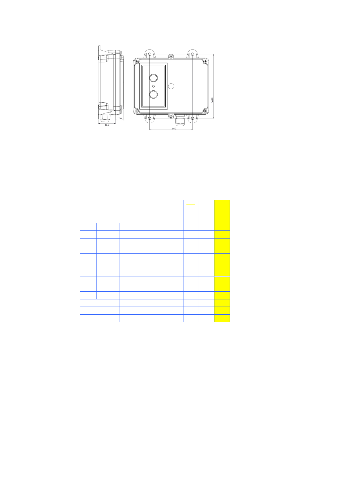
Mounting 4 external lugs
Fixings 5mm (3/16”) not supplied
IP Rating IP55
ACCESSORIES 9861, 9862, 9863 and 9869 – External Antenna with cable.
92 Series
9200RX 9202RX
9204RX
BUILD SPECIFICATION TABLE FOR MODELS IN
THIS RANGE
Ident
Legend
Connection
+ - F1 F2
Positive, Negative, F1 and F2
S S S
F3 F4 M
F3, F4, and Master
M S
ST -
STOP and -
S S S+ S-
S+ S- S S
ANT
Internal Antenna
S S S
SMA
Connector (external antenna)
S S
LK1 P Master - Parallel
C C
LK2 C Master – Continuous
C C
LK3
RS232
RS232 S
S
3 metres 4 core
S
3 metres 7 core
S S 9801 Lo-Cover
S = Standard. M = Standard but Master only connected. C = Customer configured (see “Factory Settings”).
+ Positive 8-36V supply
- Negative 0 Volts
F1 to F4 Outputs to F1 through F4
M Master Output
STOP - STOP, when grounded shuts down the Receiver
S+ S- Master Secondary for Safety solenoid connections etc.
ANT Blade connector for internal antenna
SMA Aerial connection for optional external antenna (internal antenna must be removed)
LK1 Master Selection by Jumper (Parallel)
LK2 Master Selection by Jumper (Continuous)
Factory Settings 418/915MHz configured Parallel, 433.92MHz configured Continuous
RS232 RS232 for Wired Remote and interface to access special programmes
Page 4

w92004.09
COMPLIANCE
REG 10 EC Type-approval mark E11 037601
EC Type-approval No: e11/72/245*2009/19*7601*00
FCC FCC CFR 47 Part 15.109
433.050MHz to 434.790MHz
FCC CFR 47 Part 15.109
902.025MHz to 927.975MHz
IC ICES-003 Issue 6.
433.050MHz to 434.790MHz
ICES-003 Issue 6.
902.025MHz to 927.975MHz
CE RED Directive
ETSI EN 300 220-2 v3.2.
ETSI EN 300 220-1 v3.1.1.
ETSI EN 301 489-17 V3.1.1,
ETSI EN 301 489-1 V2.1.1
433.050MHz to 434.790MHz
Australia/NZ ETSI EN 300 220-2 v3.2.1
ETSI EN 301 489-1 V2.1.1
433.050MHz to 434.790MHz
915.025MHz to 927.975MHz
RoHS Directive 2011/65/EU
 Loading...