

Page 1
Locus Engineering Inc.
E2620 Auxilliary Power Unit
(APU) & Battery Monitor
User Guide
August 07, 2018
Page 2

Table of Contents
Description.........................................................4
Features..............................................................4
Specifications.....................................................5
Detailed Description..........................................6
Installation..........................................................8
Safety..................................................................9
Maintenance.....................................................10
Troubleshooting...............................................10
Support.............................................................11
Warranty............................................................11
Please read and understand this guide before using the unit. It
contains important safety information as well as operating and
maintenance advice.
2
This device is not authorized for use with any product where the failure or malfunction of
this device can reasonably be expected to cause injury or death. This device is not
authorized for use in any life support system due to the risk of injury or death.
Page 3

E2620 Auxilliary Power Unit User Guide
Description
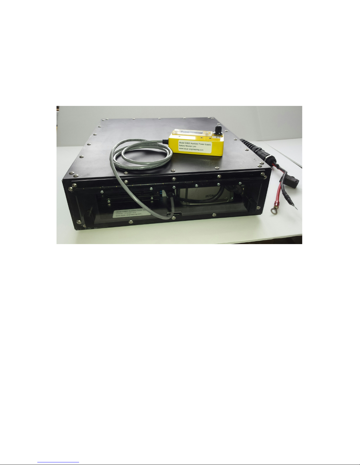
The E2620 Auxilliary Power Unit (APU) and Monitor is an inverter,
charger, and monitor unit designed to run non-life essential
equipment from an external sealed lead acid battery. The unit is
easy to use and allows equipment to be away from a 120VAC wall
outlet source for a few hours while using on-board power to
operate it.
Features
• allows mobility away from line power
• up to 400W of 120VAC pure sine wave power to run non-
life critical equipment
• ~4.6hrs@ 150W, ~2.3hrs@300W, ~1.7hrs@400W (70Ah
battery)
• overload, undervoltage, and overvoltage protected
• easy to use single rotary switch controls Off, Standby, Run
• battery monitor displays internal temperature, battery
voltage, battery guard voltage
• graceful low voltage warning with bargraph display,
voltmeter, and flashing light allows time to return
• customizable product and installation
• includes both inverter and charger connected to battery
for convenient operation
• thermostat controlled fans
• environmentally protected
• battery recharging within 4 hrs
3
This device is not authorized for use with any product where the failure or malfunction of
this device can reasonably be expected to cause injury or death. This device is not
authorized for use in any life support system due to the risk of injury or death.
Page 4

E2620 Auxilliary Power Unit User Guide
Specifications
Operating Temperature -20C to +70C
Storage Temperature -40C to +85C
Power external sealed lead acid battery,
12V nominal, ~70AHr capacity
Battery Life approx. 2-3 hrs continuous with a
300W load
Battery Guard Capacity 40A max
Battery Guard Cutoff 11.25V (programmable)
Inverter Type 12VDC to 120VAC pure sine wave
Inverter Output Power up to 400W, 85% efficiency
Inverter Input Current ~30A @ 300W, ~40A @ 400W
Charger Battery Capacity 50Ah to 500Ah
Charger Input Current 6A max @ 120VAC
Charger Output Current 25A max @ 12V to 15.7V
Charge Time approx. 4 hrs
Fan Turn On Temp. 27C
Fan Turn Off Temp. 25C
Fan Controller dual analog and digital control
Temp. Sensor +/- 1C
Volt.Sensor +/- 0.1V
Inverter Charger Size 16”L x 14.75W” x 4.5H”
40.6cm x 37.5cm x 11.4cm
Battery Monitor Size 4.4”L x 2.4”W x 2.0”H
11.2cm x 6.1cm x 5.1cm
Weight not incl. batteries 15.9lbs or 7.2kg
4
This device is not authorized for use with any product where the failure or malfunction of
this device can reasonably be expected to cause injury or death. This device is not
authorized for use in any life support system due to the risk of injury or death.
Page 5

E2620 Auxilliary Power Unit User Guide
Detailed Description
The Auxilliary Power Unit or APU is housed in a rectangular
modular aluminum enclosure which is black anodized for
protection against corrosion, and to help with heat dissipation.
This unit includes a battery cable, a 40A battery guard, a 600W
inverter, a 25A battery charger, a fan controller, and a connector
to the battery monitor.
Power Input
Battery power at a nominal 12V enters the unit via the battery
cable to a terminal block, which is a common connection point for
the other system components.
Battery Guard
The battery guard is a protective switch between the battery and
the inverter which is normally on when the input battery voltage
is above a programmed threshold. Once the battery voltage
drops below this threshold, the switch is turned off so the inverter
load does not discharge the battery any further in order to protect
the battery against excessive discharge which would adversely
affect its lifetime. The battery guard is limited to a 40A load
which represents a ~400W maximum load at the inverter output.
Loads greater than 400W will cause the battery guard to
shutdown until the overload is removed. The battery guard is
enabled on or off by the battery monitor.
Inverter
The inverter converts the 12VDC battery power to a 120VAC pure
sine wave output through two standard 120VAC outlets. A USB
port is also available to power or recharge 5V USB devices. The
output power rating is up to 600W continuous although the
5
This device is not authorized for use with any product where the failure or malfunction of
this device can reasonably be expected to cause injury or death. This device is not
authorized for use in any life support system due to the risk of injury or death.
Page 6

E2620 Auxilliary Power Unit User Guide
battery guard limits this to about 400W. The input current is
approximately 10A per 100W of output load after taking into
account the 85% inverter efficiency.
The battery duration can be estimated from
hours=battery capacity in Ah x 10/load power in watts
E.g. for a 70Ah battery with a 300W output load,
hours = 70Ah x 10 / 300W = 2.3h
Battery Charger
A 25A battery charger recharges the battery whenever it’s power
cord is plugged into a 120VAC outlet. Normally the power cord is
stored inside the enclosure to protect it. The battery charger has
an intelligent charge algorithm that recharges the battery in a
manner to offer the maximum life for the battery. A discharged
battery can be expected to be recharged in 3-4 hours. To ensure
the quickest battery recharge, it is recommended to not recharge
the battery while the inverter is running. For loads of 250W and
greater, the inverter input current will be greater than the battery
charger current, so the battery will never recharge. For lighter
loads there is a possibility the battery guard may shutdown due to
overvoltage on the battery during the final charge phase.
Cooling
The inverter, battery guard, and battery charger produce heat due
to inefficiencies. The inverter and charger have internal fans to
remove internal heat, and this heat then needs to be removed
from inside the enclosure to the outside. A fan controller controls
two fans based on the values of two temperature sensors. Above
an internal temperature of 27C, the fans turn on and stay on until
the temperature has lowered to below 25C.
6
This device is not authorized for use with any product where the failure or malfunction of
this device can reasonably be expected to cause injury or death. This device is not
authorized for use in any life support system due to the risk of injury or death.
Page 7

E2620 Auxilliary Power Unit User Guide
Battery Monitor
The battery monitor provides a switch function, a monitor
function, and a warning function. The switch has Off, Standby,
and On settings. When Off, the system draws no power. In
Standby mode, only the battery monitor is on, and the battery
voltage (VB), the battery guard output voltage (VG), and the
internal temperature (in ‘C) are displayed in sequence. The
battery voltage includes a bargraph display indicating the
remaining battery capacity. Each bar represents 10% starting
from 100%, so eight bars represent 100% capacity, and a single
bar represents 30%. There are two LEDs on the battery monitor.
The red LED turns on when the battery guard has turned off due
to the battery voltage dropping below the programmed
threshold; the inverter will also be off at this point. The orange
LED is a graceful low voltage warning which flashes faster as the
battery voltage drops beyond 20% capacity. Its purpose is to alert
the operator that the battery will soon be depleted and that the
connected equipment will also soon be shut off. The rate of
battery depletion and the remaining time to seek a battery
recharge and equipment reconnection to an alternate 120VAC
outlet will depend on the equipment load.
The connector for the battery monitor is located behind the
access door at the rear of the unit, and located between the
inverter and the charger. Normally the battery monitor cable
remains connected.
Installation
It is recommended that the APU unit and battery monitor be
installed by a professional installer with regard to the specific
installation requirements.
7
This device is not authorized for use with any product where the failure or malfunction of
this device can reasonably be expected to cause injury or death. This device is not
authorized for use in any life support system due to the risk of injury or death.
Page 8

E2620 Auxilliary Power Unit User Guide
Location
The APU should be mounted in a horizontal position and
protected from the elements and out of the way. The unit can be
mounted on a shelf with a retainer to prevent it from being
dislodged while in motion. The unit mount should also include
drain holes to prevent any water from accumulating.
Cooling Considerations
The airflow is from the rear intake louvers (at the sides) to the
front exhaust louvers, so a generous airspace over one inch
should be allowed for around both the intake and the exhaust
louvers as well as a straight and unimpeded access to open air.
The mount should not restrict or contain the air otherwise the
inverter will shut down due to excessive heat buildup.
Connections
Equipment power plugs can be plugged into the inverter, and the
access door closed to prevent any rain or snow from entering the
unit. The equipment power cables can be restrained with VELCRO
hook and loop fastener straps. The battery monitor should be
located where the operator can see the display and warning LEDs,
as well as operate the power switch. The battery monitor cable is
connected to the unit within the access door. It is a keyed twist
and turn connector.
Battery
The battery should be selected for capacity while considering the
weight. The battery should be mounted such that the battery
cable is free to move without strain. The battery cable is supplied
with a mating high power connector and fused leads for the
battery. The mating connector needs to be attached to the
battery enclosure in a manner that prevents rain entry.
8
This device is not authorized for use with any product where the failure or malfunction of
this device can reasonably be expected to cause injury or death. This device is not
authorized for use in any life support system due to the risk of injury or death.
Page 9

E2620 Auxilliary Power Unit User Guide
System Check
Once the battery, battery monitor, and equipment are connected,
turn the battery monitor switch to Standby and check that the
battery voltage, battery guard voltage, and temperature are
displayed. Turn the battery monitor switch to On, and verify that
the battery guard voltage closely matches the battery voltage,
and that the equipment is on and functioning. Ensure that the
inverter switch behind the access door is on, and the attached
equipment is on.
9
This device is not authorized for use with any product where the failure or malfunction of
this device can reasonably be expected to cause injury or death. This device is not
authorized for use in any life support system due to the risk of injury or death.
Page 10

E2620 Auxilliary Power Unit User Guide
Safety
Charge the unit at room temperature and in a well
ventilated space.
Do not place foreign objects inside the enclosure.
Do not operate the unit if wet. Turn off the unit and open
the access door as soon as possible to drain and remove
any water or dampness, and let the unit dry.
Dispose of depleted batteries at your local battery
recycler.
Ensure that the total attached electrical load is within the
limits of the inverter.
Ensure the access door is closed to protect against rain or
snow.
To ensure the quickest battery recharge, it is
recommended to not charge the battery while the inverter
is running.
10
This device is not authorized for use with any product where the failure or malfunction of
this device can reasonably be expected to cause injury or death. This device is not
authorized for use in any life support system due to the risk of injury or death.
Page 11

E2620 Auxilliary Power Unit User Guide
Maintenance
The inverter charger unit requires little maintenance beyond
replacing the battery once it has reached its end of life.
The enclosure and battery monitor can be cleaned with a damp
cloth and mild soap.
Coil the charger cable and store it inside the unit when not in use.
Troubleshooting
Unit doesn't work
check battery voltage is present when switch is in standby
check battery guard voltage is present when switch is on
remove and check fuse for continuity using a multimeter
set to ohms
recharge battery if voltage bargraph display is off
open the access door and check that inverter switch is on
Overheating and Shutdown
return equipment indoors
allow unit to cool down before re-charging battery
Short Battery Life
have battery checked and replace battery if necessary
11
This device is not authorized for use with any product where the failure or malfunction of
this device can reasonably be expected to cause injury or death. This device is not
authorized for use in any life support system due to the risk of injury or death.
Page 12

E2620 Auxilliary Power Unit User Guide
Support
Product support is available at [email protected] and at
613-831-2172. We also welcome your feedback in order to
continually improve our products.
The E2620 Auxilliary Power Unit (APU) and Monitor is easily
customizable to meet the needs for a variety of installations.
Contact Locus Engineering with the details of your application at
[email protected]
Warranty
Locus Engineering Inc. warrants this product to be free of defects
in workmanship and materials for a one year period. It is
understood that this unit is a prototype unit that may require
modifications or improvements to meet customer requirements.
This unit will be repaired or modified within the warranty period
subject to the following conditions:
the warranty will not apply to normal wear or consumable
items such as batteries
the warranty will not apply to reverse battery installation
the warranty will not apply if unauthorized repairs or
modifications are made
12
This device is not authorized for use with any product where the failure or malfunction of
this device can reasonably be expected to cause injury or death. This device is not
authorized for use in any life support system due to the risk of injury or death.
 Loading...