

Loctite Zeta 7740 Operation Manual
EQUIPMENT
Operation Manual
Loctite® Zeta® 7740 UV Curing Wand System
Part Number 98157

TABLE OF CONTENTS
1. PLEASE OBSERVE THE FOLLOWING............................................................................................................3
1.1 EMPHASIZED SECTIONS....................................................................................................................................3
1.2 ITEMS SUPPLIED...............................................................................................................................................3
1.3 FOR YOUR SAFETY ..........................................................................................................................................3
1.4 FIELD OF APPLICATION, (INTENDED USAGE) ...................................................................................................4
2. DESCRIPTION .......................................................................................................................................................4
2.1 THEORY OF OPERATION ...................................................................................................................................4
2.2 OPERATING ELEMENTS AND CONNECTIONS, REFERS TO FIGURE 1...................................................................5
3. TECHNICAL DATA...............................................................................................................................................7
3.1 ENERGY REQUIREMENTS.....................................................................................................................................7
3.2 DIMENSIONS.....................................................................................................................................................7
3.3 UV OUTPUT CHARACTERISTICS.......................................................................................................................7
4.INSTALLATION......................................................................................................................................................7
4.1 SPACE REQUIREMENTS ........................................................................................................................................7
5. OPERATING THE UNIT.......................................................................................................................................8
5.1 INSERTING AND REMOVING THE LIGHT GUIDES ..................................................................................................8
5.2 POWERING UP......................................................................................................................................................8
5.3 SETTING EXPOSURE TIME....................................................................................................................................9
5.3.1 Timed Mode................................................................................................................................................9
5.3.2 Setting Exposure Time / Manual Mode ......................................................................................................9
5.3.3 Lamp Hours.................................................................................................................................................9
5.4 ADJUSTING DUAL WAND FOR MAXIMUM OUTPUT............................................................................................10
5.5 USING FOOT SWITCH / REMOTE DEVICE............................................................................................................11
6. CARE AND MAINTENANCE.............................................................................................................................12
6.1 REPLACING THE LAMP MODULE ....................................................................................................................12
7.TROUBLESHOOTING.........................................................................................................................................13
8.DOCUMENTATION.............................................................................................................................................14
8.1 WIRING DIAGRAM..........................................................................................................................................14
8.2 PIN CONNECTIONS.............................................................................................................................................14
8.3 REPLACEMENT PARTS AND ACCESSORIES......................................................................................................15
9.WARRANTY.......................................................................................................................................................... 16
1. Please Observe the Following
1.1 Emphasized Sections
WARNING!
Refers to safety regulations and required measures that protect the operator or other persons
from injury or danger to life.
Caution!
Emphasizes what must be done or avoided so that the unit or other property is not
damaged.
Notice:
Gives recommendations for better handling of the unit during operation or adjustment, as
well as for service activities.
1.2 Items Supplied
1 ZETA® 7740 UV Wand System
1 Pair of UV protective glasses
1 Foot switch
1 Users manual
1 Power cord
1.3 For Your Safety
For safe and successful operation of the unit, read these instructions completely. If the
instructions are not observed, the manufacturer can assume no responsibility. Be sure to
retain this manual for future reference.
WARNING!
Always wear the included UV safety glasses or glasses that conform to ANSI Z87.1/CSA
Z94.3 when operating the unit.
WARNING!
Always cover hands, face and other parts of the body that may be exposed to UV light.
WARNING!
Never look into the end of the light guide.
WARNING!
Never open the shutter mechanism without the light guide installed.
WARNING!
Never remove the cover of the unit without first switching the power off and unplugging
the power cord.
WARNING!
Damage to the power cord or the housing can result in contact with live electrical parts.
Check the power cord and housing before each use. If the power cord or unit is damaged,
do not operate.
The unit may be repaired only by a Loctite authorized service technician.

1. Please Observe the Following (continued)
Caution!
Never turn the unit on without the lamp connected to the power supply.
Caution!
The energy emitted from the end of the light guide can heat any surface that it is directed
at. Care must be taken to determine the proper offset distance and exposure time.
Caution!
Turning the lamp on and off frequently will cause the UV output of the lamp to decline at
a faster rate. It is recommended that the unit be left on during breaks and short down
times.
Caution!
Avoid making sharp bends in the light guide, as this will cause a loss of UV energy or
possibly cause permanent damage. To prevent permanent damage, the minimum bend
radii are 2.4 inches for the single light guide and 1.6 inches for a dual light guide.
1.4 Field of Application, (Intended Usage)
This Loctite® ZETA® 7740 UV Wand System is designed for use with light cure
products that cure when exposed to ultraviolet and/or visible light. The system can be
operated manually or in the timed mode and is capable of interfacing with a PLC
controlled unit.
2. Description
2.1 Theory of Operation
The ZETA® 7740 UV Wand System utilizes a high-pressure mercury arc lamp with a
universal power supply and a liquid filled light wand (supplied separately). When the unit
is switched on, the proper electrical power is immediately supplied to the lamp. It will
take several minutes for the lamp to reach full power. Once the lamp has reached full
power the unit is ready to cure adhesive. Curing will take place when the UV light is
directed at the liquid adhesive. Engaging the foot switch opens the shutter and the UV
energy produced by the lamp is immediately transmitted through the flexible light guide.
The time required to complete the curing process depends primarily on the offset distance
from the end of the wand to the surface of the adhesive and the type of adhesive being
.
used
The exposure time can be controlled in either the manual mode or the timed mode.
Depressing the foot switch operates the manual mode. The shutter will remain open as
long as the foot switch is engaged. In the timed mode, setting the countdown timer from
zero to 99.9 seconds controls the exposure. The timed exposure starts by momentarily
engaging the foot switch. This action begins the timer and the shutter will remain open
until the countdown timer reaches zero. The ZETA
external devices using the foot switch 9 pin D connector and making a dry-contact relay
closure across pins 1 and 9.
®
7740 can also be actuated by

2. Description (continued)
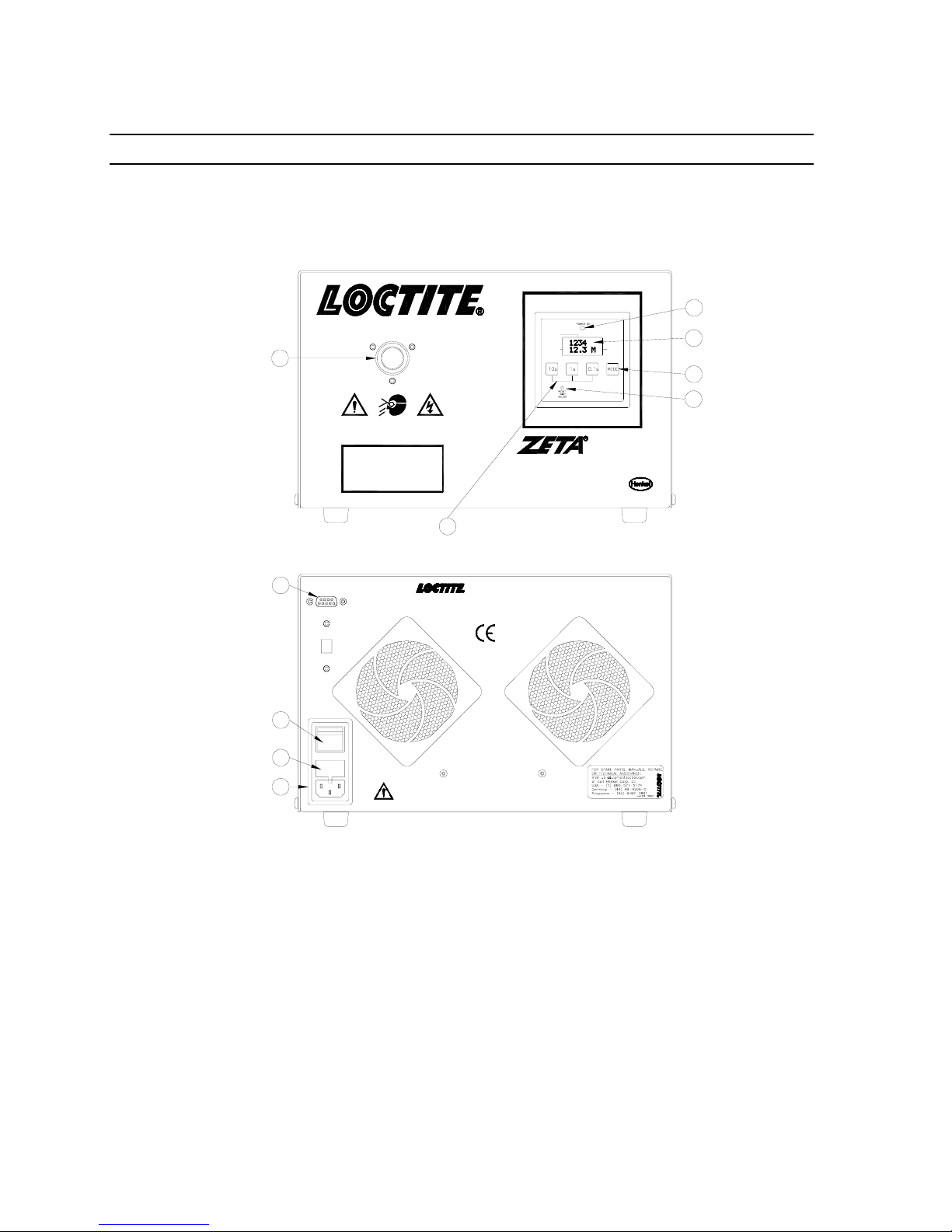
2.2 Operating Elements and Connections, refers to Figure 1
1 Power Inlet Module
Connect line cord to power inlet module.
2 Power Fuse Holder
Fuse is located in the power module.
3 Power Switch
4 Foot Switch Connection
Standard 9 pin “D” connector for foot switch or other external switch.
5 Light Guide Receptacle
Is used to retain the light guide.
6 Power Indicator
When illuminated the unit is “ON.”
7 Display
Displays the exposure time, lamp hours, and the mode.
Exposure Time
Indicates the time of the UV exposure per cycle. In manual mode, the time that
the shutter has been kept open by depressing the footswitch is shown. In timed
mode, the pre-set exposure time is shown.
Lamp Hours
The hour meter indicates the cumulative time that the lamp has been ON.
Mode
“M” indicates manual mode and “T” indicates timed mode.
Time Set Buttons
These buttons re sued in the timed mode to set the exposure time per cycle.
8 Mode Selector – Manual/Timed
When set to “manual” the UV light is passed through the light guide for as long as the
foot switch is depressed. In the “timed” mode, the timer’s LCD display indicates
exposure time and the cycle is initiated when the foot switch is momentarily
depressed.
9 Hour Meter Reset Button
Resets the hour meter to “0” when the button is depressed.
Notice: This should only be done when a new lamp is installed.
10 Time Set Buttons
Sets curing time duration.
2. Description (continued)
Light
5
Guide
Receptacle
Warning: UV Energy is transmitted from the end of the
light guide. Protective eyewear equipped with side shields
are required that meet ANSI Z80.3 & Z87.1 Certification.
Foot
4
Switch
Connection
Spare Components
P/N
98339
983677
983684
983800
Item No. 98157
UV
Description
Lamp & Reflector
Single Light Guide, 1M
Dual Light Guide, 1M
Single Light Guide, 1.5M
10 Time Set Buttons
Input: 90-132 VAC, 50/60 Hz., 1.4 A @ 120 VAC
Input: 180-265 VAC, 50/60 Hz, 0.7 A @ 240 VAC
Made in U.S.A., Technical Assistance: 1-800-Loctite
LAMP
HOURS
EXPOSURE
TIME
UV Wand System
Rocky Hill, Connecticut 06067, U.S.A.
Fuse: 4 Amp, 250 VLamp: 100 Watt
MODE
7740
6
7
8
9
Power
Indicator
Display
Mode
Selector
Lamp Hour
Reset
Power
Switch
Fuse
Holder
Power
Inlet
Module
3
2
2
Warning
Disconnect and Refer to
Manual Before Servicing Unit.
Figure 1.
 Loading...