

Loctite Zeta 7411-S Instruction Sheet

EQUIPMENT
®
Loctite
Part Number 98420
Installation Instructions:
1. Remove shutter assembly from the shipping box.
2. The Zeta
head should also be unplugged.
3. Loosen the locking nut on the Plate and Column Assembly post and remove the lamp
assembly. Place the lamp assembly so that the glass is facing upward.
Hold the filter glass when removing the mounting screws. The glass may slip off during
the disassembly.
4. Remove the flexible UV shield and mounting ring by removing (4) screws at the corners
of the underside of the Lamp Housing Assembly.
5. Place the glass in a safe place from being damaged.
6. The shutter assembly can now be installed. The dial timer and start pushbutton face the
front of the unit.
Zeta® 7411-S Shutter System Assembly
®
7411-S unit should be cool and unplugged. The cable assembly to the lamp
Instruction Sheet
Connector plug
7. Locate (4) #8-32 x 2 1/2 Phillips Pan Head Screws included with the shipment. Also,
observe the flush mounted connector on the shutter’s topside. This connector will mate
with the flush mounted connector on the front underside of the Zeta
®
7411-S Lamp
Assembly.
8. Once the Shutter and Lamp Assembly are mated, place the UV Filter Glass, UV Shield
Curtain, mounting ring and attach with the 4 screws located in step 7 to the underside of
the Shutter Assembly.
9. Place the Lamp Housing Assembly on the Post and lock in place. Connect the Lamp
cable from the Base unit to the Lamp Housing connector.
10. Adjust the dial timer to a desired setting.
11. Connect the power plug of the Base unit to an electrical outlet. Turn the power switch to
the ON position. Allow the unit to warm up (5 minutes).
12. Press the green start pushbutton. The shutter should open, and remain open until the
dialed time expires.
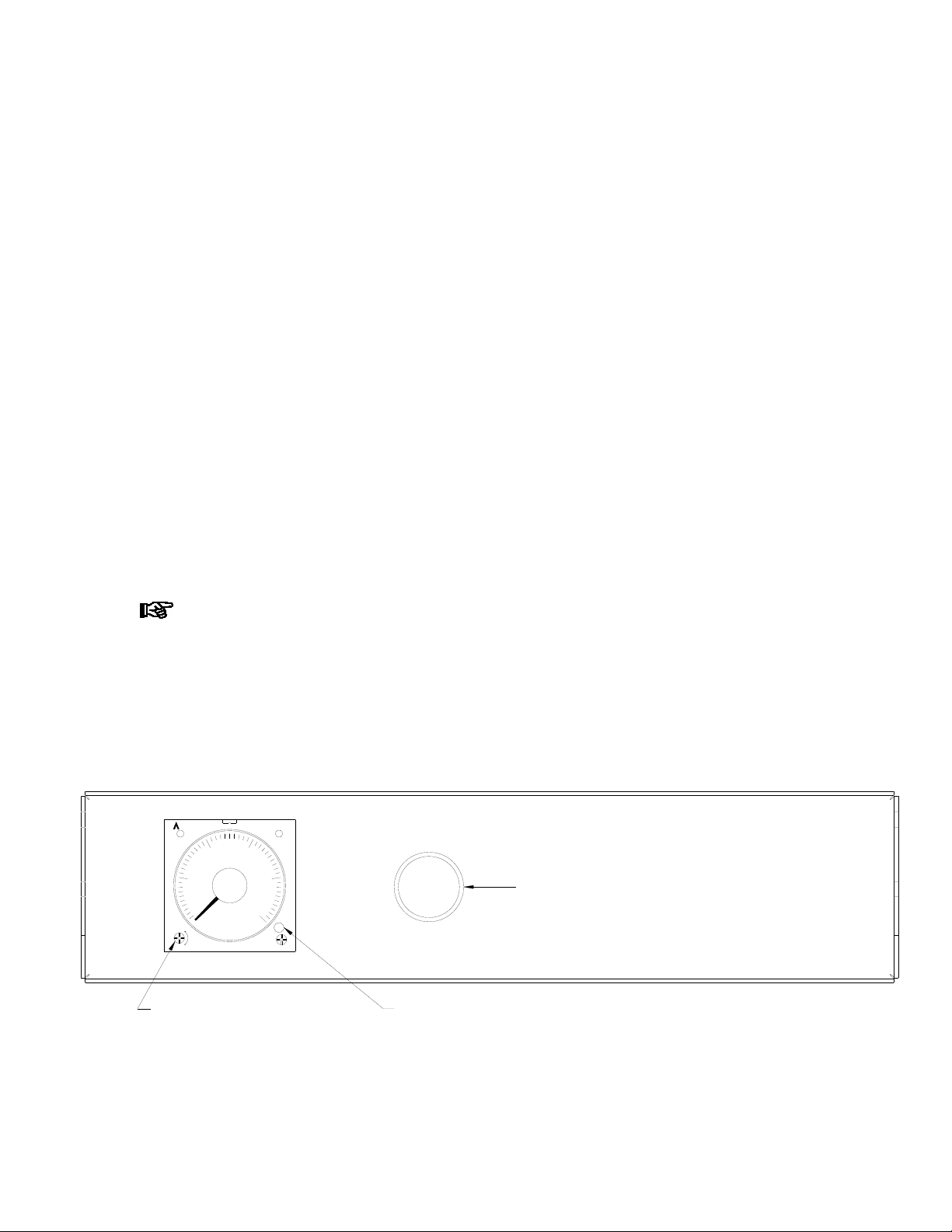
Adjusting Shutter Times:
1. The timer’s operating range is programmable. By turning the small screw at the lower left
corner of the dial indicator, the range can be changed from 0 to 500 hours.
2. To change the range of the timer to be more suitable to an application, begin with the
unit (power) turned off.
Power must be reinitialized for the cycling to change to the new settings
3. When the screw adjustment for the range is turned, the numbers and time range change
on the face of the dial indicator. Do NOT change the mode selector setting, it should
always be set at “OS”.
4. Use a small Philips screwdriver and turn the small screw adjustment (clockwise for a
longer time, counterclockwise for a shorter time) until the desired range is displayed.
SEC
50
PM4H-A
40
MODERANGE
OP
Cycle Start Pushbutton
OS
DO NOT CHANGE
SiN
POWER
20 30
10
0
S
L
Range Adjusting Screw OS Window
Turn on the power switch, and test that the shutter is cycling to the new time.
5.
 Loading...