

Loctite Single CureJet Operation Manual

EQUIPMENT
Operation Manual
START
TIMED MODE
MANUAL MODE
Panasonic
RESET
LOCK
LT4H
TIMER
POWER
UP
DOWN
CURE LIGHT ON
FAULT
Single CureJet™ Controller
Item # 1364033
For:
TM
LEDs
TM
Loctite® Single CureJet
For Use With:
Part Number 1364033, LED Controller
Part Number 1369539, CureJet
Part Number 1369538, CureJet
Part Number 1369537, CureJetTM Indigo
TM
TM
375
405
LED System
TM

TABLE OF CONTENTS
1. PLEASE OBSERVE THE FOLLOWING...................................................................................................3
1.1
EMPHASIZED SECTIONS.............................................................................................................................3
1.2
ITEMS SUPPLIED........................................................................................................................................3
1.3 FOR YOUR SAFETY ...................................................................................................................................3
1.4 FIELD OF APPLICATION, (INTENDED USAGE) ............................................................................................4
2. DESCRIPTION...............................................................................................................................................4
2.1
THEORY OF OPERATION............................................................................................................................4
2.2
OPERATING ELEMENTS AND CONNECTIONS, REFERS TO FIGURE 1............................................................4
3. TECHNICAL DATA........................................................................................................................................6
3.1 ENERGY REQUIREMENTS...........................................................................................................................6
3.2 D
3.3 DIMENSIONS (CUREJETTM)........................................................................................................................6
3.4 UV OUTPUT CHARACTERISTICS................................................................................................................6
3.5 O
4. OPERATING THE UNIT................................................................................................................................7
4.1
4.2 O
4.3 CURE LIGHT ON INDICATOR .....................................................................................................................8
4.4 FAULT INDICATOR ....................................................................................................................................8
4.5
4.6 USING THE FOOT SWITCH .........................................................................................................................8
4.7 USING AN EXTERNAL CONTROLLER..........................................................................................................8
IMENSIONS (LED CONTROLLER)............................................................................................................6
PERATING CONDITIONS ..........................................................................................................................6
INSTALLATION, REFERS TO FIGURES 1 AND 2............................................................................................7
PERATION...............................................................................................................................................7
CHECKING THE UNIT’S OUTPUT................................................................................................................8
5. CARE AND MAINTENANCE......................................................................................................................9
6. TROUBLESHOOTING.................................................................................................................................10
7. DOCUMENTATION...................................................................................................................................10
7.1 R
EPLACEMENT PARTS AND ACCESSORIES...............................................................................................10
1. Please Observe the Following
1.1 Emphasized Sections
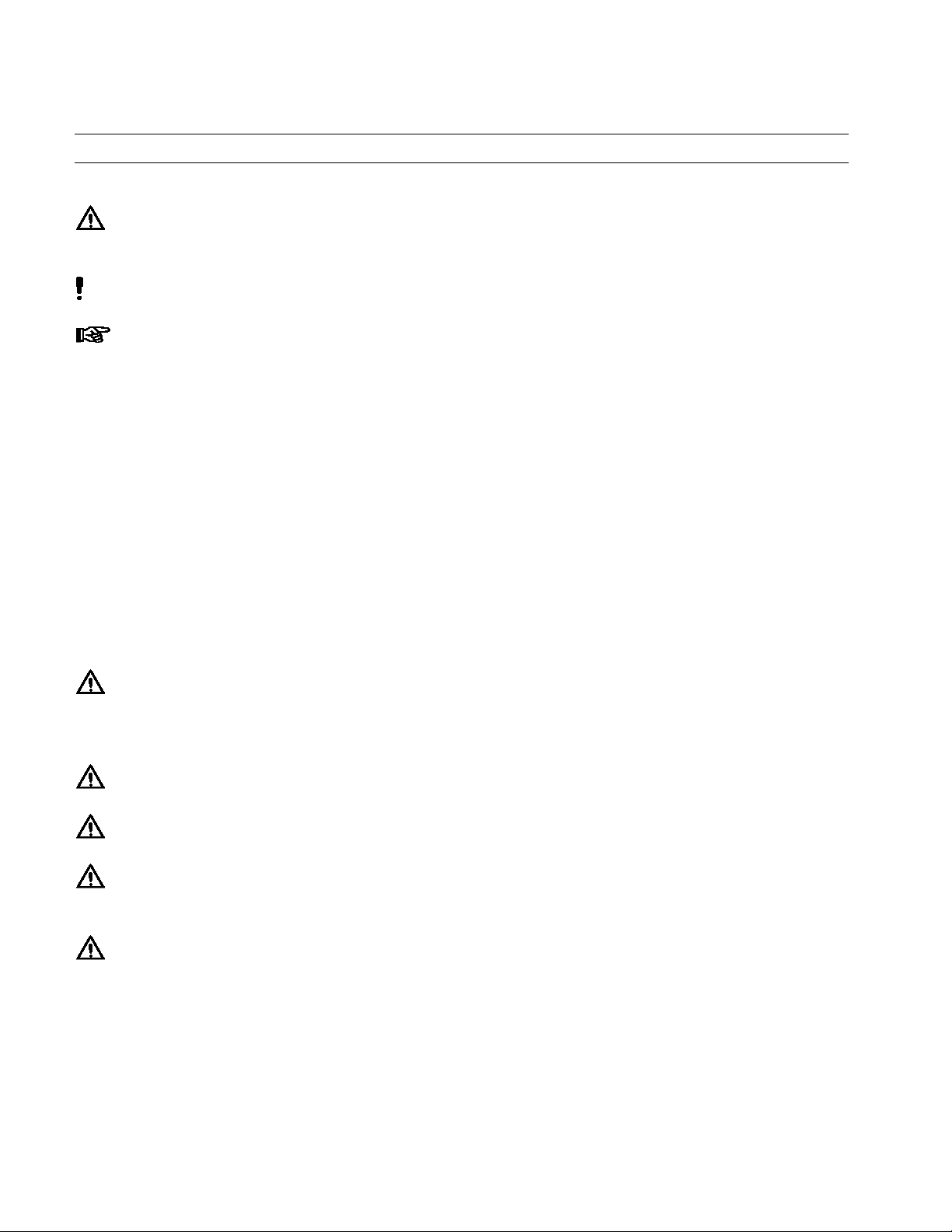
WARNING!
Refers to safety regulations and required measures that protect the operator or other persons from
injury or danger to life.
Caution!
Emphasizes what must be done or avoided so that the unit or other property is not damaged.
Notice:
Gives recommendations for better handling of the unit during operation or adjustment, as well as
for service activities.
1.2 Items Supplied
1 Loctite
1 AC Power Cord
1 Orange Safety Glasses
1 Foot Switch
1 Operation Manual
1 Side Mounting Kit
1.3 For Your Safety
For safe and successful operation of the unit, read these instructions completely. If the
instructions are not observed, the manufacturer can assume no responsibility. Be sure to retain
this manual for future reference.
®
CureJetTM Controller
WARNING!
While the Loctite® CureJetTM LED Light Sources have minimal output in the UV-A range, the
use of UV safety glasses that conform to ANSI Z87.1/CSA Z94.3 (Such as Loctite® P/N 98452)
is recommended when operating the unit.
WARNING!
Never directly expose skin to light source.
WARNING!
Never look into the end of the light source.
WARNING!
Damage to the AC power cord can result in contact with live electrical parts. Check the power
cord before each use. If the power cord is damaged, do not operate.
WARNING!
1364033 Single CureJetTM Controller will operate all existing CureJetTM Light Sources and
all new CureJetTM Light Sources. LED Controller 976419 will only operate 976420 (405) LED
Light Sources, and
976418 (Indigo
TM
) LED Light Sources.
The unit may be repaired only by a Henkel authorized service technician.

Caution!
This unit will heat up under certain operating conditions. Do not obstruct the inlet to the
cooling fan or the exhaust vents. Also, do not obstruct the fan inlets on the CureJetTM or its
exhaust. The unit has an internal mechanism that shuts it off if a preset internal temperature is
reached during operation.
1.4 Field of Application, (Intended Usage)
The Loctite® CureJetTM LED System is designed for use with light cure products that cure
when exposed to ultraviolet and/or visible light. The system can be operated manually,
operated with the integrated timer, or controlled with an external switch. The system is
designed for intermittent or constant duty cycle.
2. Description
2.1 Theory of Operation
1364033 Single CureJetTM Controller will operate all existing CureJetTM Light Sources and
all new CureJetTM Light Sources. LED Controller 976419 will only operate 976420 (405)
LED Light Sources, and 976418 (Indigo
The Loctite® CureJetTM LED System utilizes a focused LED light source (The CureJetTM) and
the LED Controller. The unit is powered by the AC line cord, 985470. When the unit is
switched on, the proper electrical power is supplied to the LED resulting in immediate full
power. Curing will take place when the light is directed at the liquid adhesive. The time
required to complete the curing process depends primarily on the offset distance from the end
of the light source to the surface of the adhesive and the type of adhesive being used.
TM
) LED Light Sources.
The exposure time can be controlled in either the manual mode, the use of the integrated
control timer, or an external switch.
The unit has an internal mechanism that shuts it off if the preset internal temperature is reached
in the Controller or the CureJetTM during operation. Should this occur, the unit would not
operate until the unit has cooled below this thermal limit.
The Loctite
®
CureJetTM LED Light Source can also be actuated by a remote foot switch, P/N
97201.
2.2 Operating Elements and Connections, refers to Figure 1
1. Manual Mode/Time Mode Switch
This switch changes the mode between timed (via the control timer setting) and manual
control.
2. Start Button
Depressing the Start Button turns on the light. In Manual Mode, light will stay on until the
button is released. In Timed Mode, the light will stay on until the control timer counts
down to 0s.
 Loading...