

Loctite MM31 Operating Manual
1

2
Contents
English .................................................................................................................. 2 - 14
Deutsch ............................................................................................................... 15- 27
1
Please observe the following .......................................................................... 3
1.1
Emphasized Sections .................................................................................................. 3
1.2
Items Supplied ............................................................................................................. 4
1.3
Field of Application (Intended Usage) .......................................................................... 4
1.4
For your Safety ............................................................................................................ 4
2
Description ....................................................................................................... 5
2.1
Operating Elements and Connections ......................................................................... 5
2.2
Theory of Operation ..................................................................................................... 6
3
Technical Data .................................................................................................. 6
4
Installation ........................................................................................................ 7
4.1
Environmental and Operating Conditions ..................................................................... 7
4.2
Space Requirements ................................................................................................... 7
4.3
Start Requirements ...................................................................................................... 7
4.4
Insert the Dual Cartridge and Connect the Adapter ..................................................... 8
4.5
Connecting the Unit ..................................................................................................... 9
4.6
Adjusting the Proximity Switches ................................................................................. 9
5
Operation ........................................................................................................ 10
5.1
Changing an empty Cartridge .................................................................................... 10
5.2
Shut-off ...................................................................................................................... 11
5.3
Return to Operation ................................................................................................... 11
6
Care, Cleaning and Maintenance .................................................................. 11
7
Troubleshooting ............................................................................................. 11
8
Annex .............................................................................................................. 12
8.1
Accessories and Spare Parts ..................................................................................... 12
8.2
Pin Assignment .......................................................................................................... 12
8.3
Declaration of Conformity .......................................................................................... 13
3
1
Please observe the following
For safe and successful operation of the unit, read these instructions completely. The
manufacturer cannot be held responsible for damage or injury of any kind because of
misuse or improper application or because of failure to observe safety instructions or
warnings.
Be sure to retain this manual for future reference.
Refer to the technical data sheet of the assigned adhesive under the address
www.loctite.com or request the technical data sheet and the safety data sheet (acc. To
the EC Directive 91/155/EC) for the LOCTITE® product used at
Henkel AG & Co. KGaA
+49 89 92 68 11 67 for English version of data sheets;
089-92 68 11 22 for German version of data sheets.
Follow unconditionally the INSTRUCTIONS of these data sheets!
Important!
Do not operate the unit before reading and understanding the operating manual!
1.1
Emphasized Sections
Warning!
Refers to safety regulations and requires safety measures that protect the operator or
other persons from injury or danger to life.
Caution!
Emphasizes what must be done or avoided so that the unit or other property
is not damaged.
☞
Notice
Gives recommendations for better handling of the unit during operation or adjustment as
well as for service activities.
The numbers printed in bold in the text refer to the corresponding position numbers in
the illustration on page 5.
The point emphasizes an instruction step.
– The dash emphasizes a list.
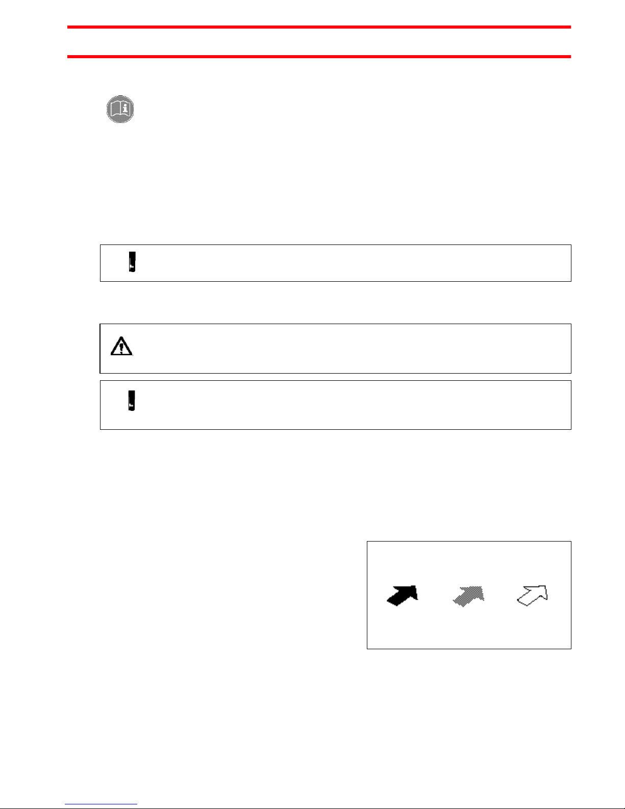
Instruction steps in the illustrations are
indicated with arrows.
When several instruction steps are
indicated in an illustration, the shading of
the arrow has the following meaning:
Black arrow = 1st step
Grey arrow = 2nd step
White arrow = 3rd step
☞
Notice!
As a result of technical development, the illustrations and descriptions in this operating
manual can deviate in detail from the actual unit delivered.
4
1
Please observe the following
1.2
Items Supplied
– 400 ml Dual Cartridge Applicator, Type MM31, Order No. 1529531
– 2m Pressure Hose
– 1 Operating Manual
When using C type cartridges the C type adapter has to be ordered separately and is
available only on request.
When using F type cartridges the F type adapter has to be ordered separately and is
available only on request.
1.3
Field of Application (Intended Usage)
The Cartridge Applicator MM31 is used to supply volumetric pumps and dispensers with
Loctite 2k-products contained in 400ml dual cartridges.
Following 2k-products are available in 400ml dual cartridges:
2k-Acrylates, 2k-MMAs, 2k-Epoxies, 2k-Silicones and 2k-MS-Polymers.
Following volumetric pumps and dispensers can be supplied:
Compact Dual Rotor Pump 97514 and HD Dispenser 97161 / 97162.
The Cartridge Applicator MM31 can be used in transfer lines, manual or automatic work
places.
1.4
For your Safety
While under warranty, the unit may be repaired only by an authorized Loctite service
representative.
Warning!
If chemical products are not properly handled, damage to health can result!
Observe general safety regulations for the handling of chemicals!
Observe manufacturer’s instructions!
Request a safety data sheet for the LOCTITE®-product used!
When working with pressurized air, wear protective glasses!
Removing, by-pass or putting out of operation of the safety devices can result in damage
to health and to the unit and is therefore prohibited!
5
2
Description
2.1
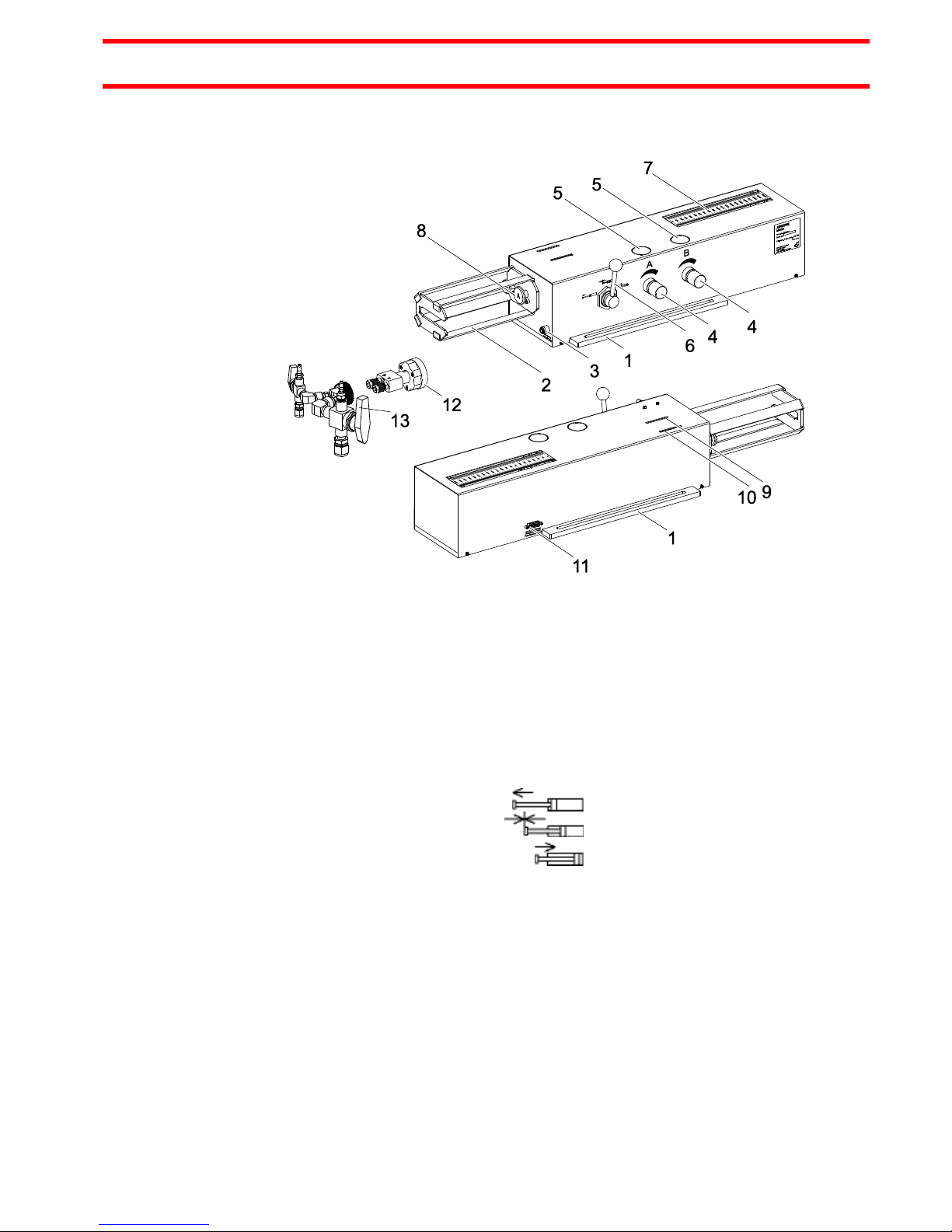
Operating Elements and Connections
1
Base Frame with slotted holes Dia. 8.5 mm *290 mm.
2
Cartridge Tray, to insert and fix the dual cartridge.
3
Pneumatic Connection. The calibrated pneumatic hose OD 6 mm from the
controller (Regulated pressure: I) has to be connected here.
Pressure input limit is max. 6 bar (87 PSI). Make sure that the limit is kept.
4
Pressure Regulator 0-6 bar, Component A and the other for Component B.
5
Pneumatic Gauge 0-10 bar, Component A and the other for Component B.
6
Hand Lever Valve Component A and Component B
State of Switching = Position of the cylinders
– Piston forward
– Keep in position
– Piston backward
7
Product Level Display for Component A and B in mm.
8
Pusher Component A and component B
9
Proximity switch, empty position of the cartridge, Component A, pin
assignment see section 8.2.
10
Proximity switch, empty position of the cartridge, Component B, pin
assignment see section 8.2.
11
15 pin Sub D Connector, male
Connection to a control unit for the following signals:
– Low Level Sensor
12
C Type Cartridge Adapter, available only on request.
13
F Type Cartridge Adapter, available only on request.

6
2
Description
2.2
Theory of Operation
The 400 ml Dual Cartridge Applicator should be pressurized via a higher-ranking
controller, e.g. PLC, with max. 6 bar (87 PSI).
The pushers 9 feed the product out of the cartridge and through the feedline to the
Compact Rotor Pump or HD Dispenser.
When connected to the main air supply directly, the pushers can be switched via the
hand lever valves to the forward position, “keep in position” or backward position at any
time.
The maximum feed rate of product depends on four factors:
1. Adjusted air pressure
2. Feed tube diameter
3. Feed tube length
4. Product viscosity
With one proximity switches (PS) per channel (component) 10/11 the position of the
pushers can be evaluated.
The PS provides the “empty” signal, dependent from its adjustment.
As soon as the “empty” signal appears, the higher-ranking controller has to stop the
dispensing and wait for the user confirmation, that
– the empty cartridge has been replaced by a filled one and
– the pushers has been switched to the forward position.
For the exchange of the cartridge, the retraction of the pushers must be performed
manually by switching the hand lever valves to the backward position, see section 5.1.
The cartridge applicator should be under pressure only during dispensing and purging.
Otherwise the applicator has to be depressurized to keep in position. The pushers
should not be retracted.
3
Technical Data
Pressure Quality
If the required quality is not achieved,
install a LOCTITE® filter regulator Type
97120
Filtered 10 µm, oil-free, non-condensing
Order Code No. 88649
Pressure input limit
(maximum feed pressure)
max. 6 bar (87 PSI).
Make sure that the limit is kept.
Dimensions (L*W*H)
810x210x170 mm (~32x8.3x6.7 inch)
Pneumatic hose
OD 6 mm , ID 4 mm
Operating Temperature
+ 5 °C…+ 40 °C (+ 60 °F…+ 86 °F)
Storage Temperature
- 10 °C…+ 70 °C (- 4 °F…+ 160°F)
Weight
~ 12.5 kg
+ 0.5 mm
– 0.1 mm

7
4
Installation
4.1
Environmental and Operating Conditions
– Avoid kinking of pressure hoses.
– Typically, the pressure hose should not be longer than 2 m.
– Do not use inflexible hoses, so that unnecessary loads on the fittings will be avoided.
– Keep all fittings tight.
– No direct sunlight; no UV light!
4.2
Space Requirements
4.3
Start Requirements
Warning!
Operate the dispenser only with inserted dual cartridge! Danger of pinching!
Operate cartridge applicator when
– Cylinder is in basic position (backward) and
– Cartridge is inserted.
The factory settings of the pneumatic flow controls need no changing in the forward
movements.
Pressure Input Limit
Caution!
Pressure input limit is max. 6 bar (87 PSI). Make sure that the limit is kept.
8
4
Installation
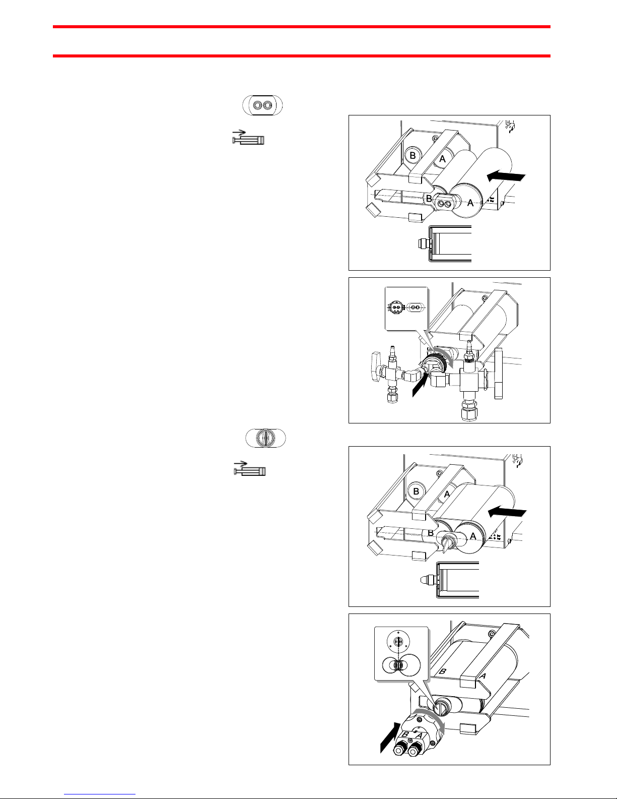
4.4
Insert the Dual Cartridge and Connect the Adapter
F Type Cartridge
Switch hand lever valve 7 to the position
„Piston backward” .
Press the dual cartridge into the
cartridge tray 2 till it stops.
Mount the mixer.
☞
Mount the F-adapter 14.
The adapter has to be ordered
separately.
Notice!
Pay attention to product holes on the
cartridge! The location of the holes in the
adapter and the adapter connection must
match.
C Type Cartridge
Switch hand lever valve 7 to the position
„Piston backward” .
Press the dual cartridge into the
cartridge tray 2 till it stops.
☞
Mount the C-adapter 13. The adapter
has to be ordered separately.
Notice!
Pay attention to the divider plate on the
cartridge! The position of the groove in
the adapter and the divider plate must
match.
 Loading...