


Sliding Gate Operator
User's Manual
Model: L110C
www.Openers4Less.com

L110C/L110 SLIDING GATE OPERATOR
2
OUTLINE
1. Important safety information
…………………3
2. Main functions
…………………………………3
3. Technical parameters
…………………………3
4. Packing list
……………………………………3
5. Installation
……………………………………5
6. Connect the wires
……………………………9
7. Adjustment
……………………………………9
8. Maintenance
…………………………………10

L110C/L110 SLIDING GATE OPERATOR
3
1. Important safety information
Carefully read and follow all safety precaution and warnings before attempting to install and
use this operator, incorrect installation can lead to severe injury.
The gate operator should be installed by a qualified technician; otherwise, serious
personal injury or property damage may occur.
The automatic gate operator must be grounded.
When opening or closing the gate, do not attempt to walk or drive through the gate.
Children should not be allowed to play near or operate automatic gates.
Install the gate operator on the inside of the property, DO NOT install it on the outside of
the property where the public has access to it.
Be careful when in close proximity to moving parts where hands or fingers could be
pinched.
The operator should be switched off before repairing it or opening its cover.
2. Main functions
The gate operator is used to drive the sliding gate, it is capable of overwork in short time.
When overloading, it has electrical and mechanical double protections to ensure operating
safety. In case of power failure, a release key allows to loosen the clutch to move the gate
manually.
3. Technical parameters
Type L110C L110
Limit switch Magnetic limit switch Spring limit switch
Power supply AC1 10, 60Hz
Output torque (Max.)
15N·m
Motor speed 1650rpm
Reduction ratio 1:30
Environmental temperature -10ºC to +55ºC
4.Packing list
After receiving the product, you should make an unpack-in spectio n, in whi ch you sh ould check
whether the product was damaged. If you have any problem please contact dealer.
L1 10C gate operator packing list
No. Item Quantity
1 Gate operator 1
2 Release key 2
3 Operator base (spare accessory) 1
4 Tighten bar 2
5 Magnet bracket 2
6 Sprocket cover 1
7 Screw for mounting driven sprocket bracket (M8X16) 4
8 Anchor bolt with nut 4
9 Driven sprocket bracket (left side & right side) 2
10
Magnet
2
11
Anchor
4

Residential Sliding Gate
Operator
Tools you will need
During assembly and installation of your opener, the instructions will call for the use of
various tools shown below. Other tools may be required as needed for the installation of
the concrete pad and electrical connection.
Table 3 Required Tools for Installation
Screwdriver Tape Measure Electric Drill Level
File Wrenches Multimeter Pliers Allen Wrenches
Wire Strippers Wire Cutter Adjustable Wrench Socket Wrench

L110C/L110 SLIDING GATE OPERATOR
4
Fig.1 L1 10C accessories
L1 10 gate operator packing list
No. Item Quantity
1
Gate operator
1
2
Release key
2
3
Operator base (spare accessory)
1
4
Tighten bar
2
5
Block bracket
2
6
Sprocket cover
1
7
Screw for mounting driven sprocket bracket (M8X16)
4
8
Anchor bolt with nut
4
9
Driven sprocket bracket (left side & right side)
2
10
Block
2
11
Anchor
4

L110C/L110 SLIDING GATE OPERATOR
5
Fig.2 L1 10 accessories
5. Installation
The L110C/L110 Chain-driven Gate Operator operates by forcing a straight piece of chain.
This length of chain is extended between two chain brackets located at opposite ends of the
gate. The entire configuration is shown in the diagram below.
Fig.3 L110C

L110C/L110 SLIDING GATE OPERATOR
6
Fig.4 L1 10
Conduit
In order to protect the wires, conduit must be preset into the concrete when it is poured. Wires
within the conduit shall be located or protected so that no damage can result from contact with
any rough or sharp part.
Concrete pad
The base unit of the gate operator requires a concrete pad in order to maintain proper stability.
The concrete pad should be approximately 300mm x 260mm x1 20mm deep in order to p rovide
for adequate operation.
Anchors
You can use the anchor bolts, anchors, washers, and nuts. These ancho rs must be set i nto the
concrete when it is poured, or you can use wedge anchors.
Chain
Sprocket bracket
Installation 2
Installation 1
Anchor
Anchor bolt
Tighten bar
Conduit
Fig.5

L110C/L110 SLIDING GATE OPERATOR
7
Driven sprocket bracket
Fix the driven sprocket bracket on both sides of the operator.
Operator
In locations where ground freeze is possible, mount the gate operator as shown in Fig.5
installation 1 or installation 2. Check the operator and make sure it is lined up with the gate.
Chain Brackets
Use the appropriate bolts to attach the chain bracket to the frame of the gate. If the gate is of
square frame style, use the square bolts shown.
Spring washer (Φ8)
Plain washer (
Φ8)
"L" bracket
Square bolt
Nut (M8)
Chain bolt
Master link
Nut (M6)
Spring washer (
Φ6)
Plain washer (
Φ6)
Gate
Square frame
Fig.6
If the gate is of round frame style, use the round bolts shown.
Round bolt
"L" bracket
Plain washer (
Ф8)
Spring washer (
Ф8)
Nut (M8)
Chain bolt
Master link
Nut (M6)
Spring washer (
Ф6)
Plain washer (
Ф6)
Gate
Round frame
Fig.7
Chain
Close the gate and attach a chain bolt to the chain using enclosure master links. Tighten the
chain bolt to the bracket with washers and nuts. Pull the chain through the sprockets to the
other chain bracket at the opposite end of the gate see Fig.9. Connect the other end of the
chain and the chain bolt, and then tighten the chain bolt to the chain bracket. Thread up the
chain by adjusting the chain bolt. Cut the chain to length if necessary. Tighten the chain by
tightening the chain bolts at either end. See Fig.8.
Master link
Chain bolt
Chain
Fig.8

L110C/L110 SLIDING GATE OPERATOR
8
Drive sprocket
Driven sprocket
Driven sprocket
Fig.9
Sprocket cover
Mount the sprocket cover with screws.
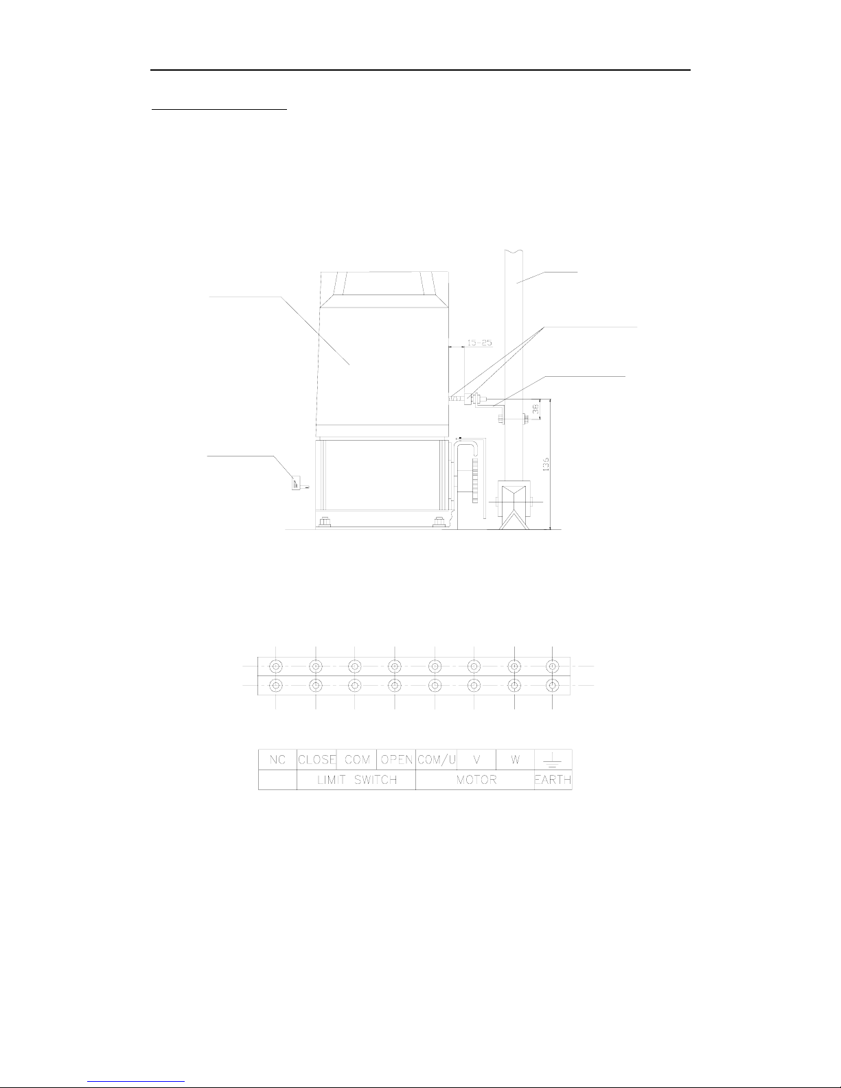
Limit switch
L1 10C-Magnets for limit switch
(see Fig.10)
Install the magnet as shown in Fig.10 below. The magnet and limit switch are used to
control the position of the gate.
When the magnet is installed, release the gear clutch and pu sh the sliding gate manually to
pre-determine the position. Fix the magnet bracket to the gate and then tighten the gear
clutch. The lower bracket is for open position and upper bracket is for close position.
Finally adjust the magnet to the proper position by moving the gate with the motor. The
magnet should be 10~15mm away from the magnetic limit switch. If it is too far away, the
switch will fail to work. Adjust the position of the magnet until the positions of the opening
and closing meet the requirement.
Please note the position of two magnet brackets (fixed plate) are different: one is
upper and another is lower. Verify and if necessary exchange the two brackets
position. Also if necessary exchange the limit switch wires CL (close) and OP
(open).
Release key
Gate operator
Gate
Upper and lower Magnets
Sprocket cover
Drive sprocket
Magnet bracket
Fig.10 L1 10C
L110C/L110 SLIDING GATE OPERATOR
9
L1 10-Spring limit switch (see Fig.11)
To ensure safety, it is recommended to install limit devices at both ends of the gate to
prevent the gate from sliding out of the rails. The rails must be installed horizontally.
The spring limit switch and blocks are used to control the position of the gate.
When the block is installed, release the gear clutch with the key and push the sliding gate
manually to pre-determine the position, fix the block bracket to the gate and then tighten
the gear clutch with the key. Moving the gate electrically, adjust the block bracket to the
proper position until the position of the opening and closing meet the requirement.
Release key
Gate operator
Gate
Spring limit
switch and block
Block bracket
Fig.1 1 L110
6. Connect the wires
Make sure that the power is OFF before making any electrical connections. Remove the cover
of the control box, perform the wiring and replace the cover again. (Refer to Fig.12)
Fig.12
7. Adjustment
Check the power supply, grounding and wiring before running the device.
Release the clutch with the key to determine whether or not the gate can be moved manually.
If everything is in good working order, engage the clutch with the key.
When engage the clutch with the key, be sure to close completely to prevent from damage.
Switch on the power and run the operator to ensure that the gate is sliding smoothly.
Adjust magnet or block position until the gate opened and closed properly at the limited
positions.

L110C/L110 SLIDING GATE OPERATOR
10
Tighten (or release) the force adjust bolt on the motor top to increase (or decrease) the output
torque (i.e. output force of the operator), and ensure the gate safely.
Adjust the output torque in the safety range before using the operator.
8. Maintenance
Ensure the power is switched off before removing the cover .
Loosen the oil screw on the motor to avoid leakage.
Ensure the operator is well earthed.
Regularly grease the wheels and axles to ensure the gate moves smoothly.
Keep opener clean at all times.

Step #2
Install the Control Board onto the Motor by mounting it on the
Step #3
Install the Receiver onto the Motor by mounting it on the small
(as shown
Step #1
Unscrew the Blue Cover from the Motor and set it aside.
Open the small white box & make sure that the contents include:
(1) - Receiver and (1) - Control Board
small white clips that are on the large Mounting Plate.
(as
shown below)
white clips that are on the small Mounting Plate.
below)
7

Step #4
Next, take the set of wires coming from the motor and connect the
red and black wires anywhere onto the plug.
Once you have connected those wires, you will then take that plug
and connect it to the Control Board on the section labeled:
MAKING THE CONNECTION
Now you will begin the installation by screwing the wires that are coming
from the small Receiver Board onto the Terminals (see Pic 1, right) from
the Control Board, in the following order:
Terminal 10 - GREEN WIRE
Terminal 11 - RED WIRE
Terminal 12 - YELLOW WIRE (any)
Terminal 13 - YELLOW & BLUE WIRE (any )
Terminal 14 - BLUE WIRE (any)
Step #5
(as shown on the pic, right)
Pic 1
"MOTOR"
(as shown on the pic, right)
8

Step #6
Find the plug with the Blue & Yellow wires on it. Connect the plug on
Step #7
Find the plug with the Red, White & Blue wires on it. Connect the plug
Step #8
Step #9
You are now ready to connect you power wires to your Gate
Opener!
to the Control Board on the section labeled:
"CAPACITOR"
(as shown on the pic, right)
on to the Control Board on the section labeled:
"LIMIT SWITCH"
(as shown on the pic, right)
Find the wire coming from the bottom of the Motor that is GREEN &
YELLOW. Screw the "Ground Wire" to Terminal #22 on the Control
Board
(as shown on the pic, right)
Terminal #1 - POWER
Terminal #2 - NEUTRAL
9

AC SLIDE GATE CONTROLLER
FEATURE SELECTOR
Limit Switch Type
ON: Normally Close
OFF: Normally Open
When using auto close features
DIP 1
10
Auto Close Feature
12.5 Seconds
25 Seconds
45 Seconds
only one
di
p sw
itch sh
ou
ld
b
e
ON. The other two dip switch
should be in the OFF posion for
the auto close feature to work
correctly.
DI P 2
DI P 3
DI P 4
Direcon of Gate
ON: Gate Opening to the le
OFF: Gate Opening to the Right
NOT USED
DI P 5
DI P 6
Receiver
Channel One (not used at this me)
Channel Two (not used at this me)
DI P 7
DI P 8

Transmitter/Remote Control (shown in Figure 9)
1. Yellow Button Channel
2. Blue Button Channel
3. Indicator Light
4. Yellow Button Channel – exposed
5. DIP Switch
6. Battery
7. Blue Button Channel – exposed
8. Back side cover
Figu
re 9
Receiver
1. Channel 1 DIP Switch (yellow
button
on remote control
transmitter)
2. Channel 2 Dip Switch
(Secondary, Multi-Code
co
mpatible, blue button on
remote control transmitter)
The
red and black wires are 24 volt
po
wer input. The two yellow are the
ch
annel 1, the two white are
ch
annel 2, and the black wire is the
antenna wire
Figure 10
Figure 10
Setting the Transmitter DIP Switches:
There
are a total of eight (8) transmitter DIP switches. Each one can be placed in three (3) different positions
(+,
0, -). DO NOT set all of the switches to the same position, for example: all +, all 0 or all -. Once the
DI
P switches have been set to a personal code, replace and close the cover.
11

Residential Sliding Gate Operator
13
Optional Equipment Installation Procedures
O
O
O
O
O
O
O
O
O
O
O
O
Blue
Brown
Black
White
Grey
Grey
Black
Black
Green
Brown
Red
Black

©2005-2009 LockMaster All Rights Reserved
sales@Openers4Less.com
www.Openers4Less.com
 Loading...