

Lochinvar XPN1302 Installation Manual

INS70111 Rev H
AQUAS™ POOL PACKAGE INSTALLATION INSTRUCTIONS
FOR MODELS: XPN 1015/1002, 1320/1302 and 1520/1502
AQUAS Pool Package
The AQUAS pool package system is a high efficiency
commercial condensing boiler package system pre-piped
to an indirect heat exchanger from the factory. This pool
heater is a low temperature operating system designed to
take advantage of the stainless steel heat exchanger and
condensing operating temperatures to ensure the highest
efficiency possible. The AQUAS is designed around a
predetermined flow, set by the manufacturer, between the
boiler and the indirect heat exchanger. The AQUAS operates
off the pool system pump itself which will continually supply
water to the indirect heat exchanger. This means there is no
need to purchase a dedicated circulator to deliver water to
this package system.
Installation Instructions
Piping
Pool / spa connections to the indirect heat exchanger are SCH 80
CPVC glue fittings. The connections from the field loop to the
heat exchanger may be done in CPVC or PVC pipe as follows:
• Use cement on the connections so they are rated for CPVC
pipe and have enough body to hold the connection.
• To make the connection, apply glue to both the CPVC flange
and the section of pipe.
• Insert the pipe into the flange until it reaches the bottom of
the flange.
• Turn the pipe a half turn in the socket to ensure that a proper
seal is made.
To achieve the optimum operating efficiency of your AQUAS
it is recommended that you keep the pool water flow of
each appliance within plus or minus five gallons per minute
of the recommended flow as stated in Table A. Low flow
through the indirect heat exchanger will result in elevated
temperatures supplied to the pool.
TABLE A
RECOMMENDED
MODEL
1015/1002 243 4"
1320/1302 316 6"
1520/1502 364 6"
RECOMMENDED CLEARANCES:
BOILER - SEE SYNC I & O MANUAL
INDIRECT HEX - ALLOW 18" FOR SERVICE ON ALL SIDES
SYSTEM
WATER FLOW
GAS INLET
CONNECTION SIZE
FLUE
CONNECTION
Pool water is designed to flow from right to left standing in front
of the boiler. A factory installed sensor is on the inlet side of the
indirect heat exchanger (FIG. 10, page 7).
The supply and return water piping to the indirect heat exchanger
shall be no smaller than 4" for Model 1015/1002 and 6" for Models
1320/1302 and 1520/1502.
Throttling Valve
A T of 8° - 10°F across the indirect heat exchanger is
recommended. Throttling valves are used to set the flow through
the indirect heat exchanger. (Standard gate valves are acceptable.)
FIG. 1_Component Location
BOILER
PUMP
SYSTEM SENSOR
LOCATION
CUPRO-NICKEL POOL
HEAT EXCHANGER
SKID MOUNTED
ON STEEL FRAME
IMG01189
TEMPERATURE AND
PRESSURE GAUGE
RELIEF VALVE
CONDENSATE
DRAIN
NOTE: Model 1502 shown for
illustration purposes only.

The system can be installed in either a Full Flow or Diverted
Flow orientation:
Full Flow (reference FIG. 8)
If the total system flow of the swimming pool or spa system
is within five gallons per minute of the recommended system
water flow as shown in Table A on page 1, this type of system is
recommended.
Diverted Flow (reference FIG.’s 9 & 10)
Apply a small amount of a high quality RTV silicone sealant to
the threads to prevent leaks and install the limit and bulbwell
into the threaded opening in the pipe. Install the limit control
and bulbwell and tighten to seal. Do not over-tighten either part
into the threaded opening in the PVC pipe. Over tightening can
damage the parts and/or strip the threads cut into the plastic pipe.
Wire the 115°F limit into the pool heater control circuit as shown
in FIG. 2 on page 3. If additional wire length is needed, use 18
gauge wire for distances up to 30 feet. For longer distances, size
the wire per Table B.
Criteria for installing a diverted flow system is as follows:
• If the total system flow is greater than the amount
required by the indirect heat exchanger.
• Installations with temperatures in excess of 95°F. This is
necessary so the pool high limit will not trip. No water
should enter the pool / spa in excess of 115°F. If the heat
exchanger pool outlet is in excess of 115°F the water must
be tempered down.
• Multiple unit installation.
Example: Total system flow is 1000 gallons per minute (GPM).
If two 1,500,000 Btu/hr units were installed, each of the pool
packages would require 364 GPM for a total of 728 GPM of the
pool water being diverted through the indirect heat exchangers,
while the other 272 GPM would be diverted back to the pool.
Auxiliary Mixed Water Limit Control
Ensure that the auxiliary 115°F mixed water limit control is
installed in the filter system piping. Install the auxiliary limit a
minimum of three feet downstream from the point where the
heated water from the indirect heat exchanger is added to the
filtration system (see FIG.’s 8 - 10). If the water leaving the heat
exchanger is in excess of 115°F a bypass must be installed to
temper the water below 115°F before re-entering the pool/spa.
TABLE B
Remote Wire Connection
WIRE GAUGE
12 GA 100 ft.
14 GA 75 ft.
16 GA 50 ft.
18 GA 30 ft.
MAXIMUM ALLOWABLE
LENGTH
The limit will be mounted in a 3/8" NPT tapped fitting installed
in the filtration system piping or it may be installed directly into a
tapped opening in the PVC filter system piping. Turn off the filter
system pump when installing the auxiliary limit in the filtration
system piping. Tapped openings can be added to the PVC pipe by
first drilling 9/16" pilot holes in the PVC pipe at least three feet
downstream of the point where the heated water from the indirect
heat exchanger is added to the filter piping. The drilled pilot holes
can now be carefully threaded with a 3/8" NPT tap. After the
pipe threads have been cut into the PVC pipe wall the limit and
bulbwell can be inserted into the tapped openings.
INS70111 Rev H
2
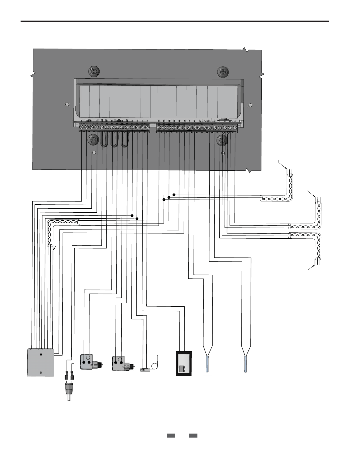
FIG.2_Low Voltage Connections
1 ALARM
2 CONTACTS
3 RUN TIME
4 CONTACTS
5 LOUVER
MOD BUS
B
LBL20052 REV
ENABLE
7 MODULE 2
8 FLOW SWITCH
9 MODULE 1
6 PROVING
10 FLOW SWITCH
11 TANK
12 THERMOSTAT
13 R
15 SHIELD GND
14 W
16 A
17 B
0 - 10V INPUT
21 SYSTEM
20 (-)
18 SHIELD GND
22 SENSOR
19 (+)
23 OUT DOOR
24 SENSOR
CASCADE
26 SENSOR
25 TANK
27 SHIELD GND
30 SHIELD GND
29 A
28 B
SHIELD
MODBUS COMMUNICATION BUS
TO NEXT BOILER
A
B
R
E
L
OI
B
D
T
L
X
E
I
E
H
N
S
TO
A
B
SHIELD
B
A
BUILDING
MANAGEMENT
SYSTEM
115°F HIGH LIMIT SENSOR
A
B
R
D
L
E
L
E
I
H
OI
S
B
S
OU
I
EV
R
P
OM
FR
MODULE 2
MODULE 1
TANK
THERMOSTAT
SYSTEM SENSOR
ENABLING DEVICE
TANK SENSOR
IMG00232
INS70111 Rev H
3

Line Voltage Connections
The AQUAS pool package has a single point line voltage
connection for the boiler and the pump (FIG. 3). Connect 120
VAC wiring to the line voltage terminal strip in the junction box.
Provide and install a fused disconnect or service switch (20 amp
recommended) as required by local codes. Refer to Table C for
total amps by model.
Figure 3 Line Voltage Field Wiring Connections
120V SUPPLY
Models
Total Amps
TABLE C
1015/1002 - 1520/1502
14.3
DHW1/
SPA 1
RLY20038
RLY20040
NEUTRAL
GROUND
LINE
DHW2/
W
SPA 2
G
L
B
24 68
01
W
G
BK
SERVICE SWITCH
W
G
L
B
B
PUMP 1
W
BK
PUMP 2
W
B
BK
JUMPER
BK
BK
INS70111 Rev H
4

Indirect Heat Exchanger
Installation Instructions
Heat exchangers should be installed downstream of the pumping and filtration equipment (FIG. 4).
FIG. 4_Pumping and Filtration Equipment
TOP VIEW
Pool Water Chemistry
It is essential that the instructions in this section and the Ryznar
Stability Index and/or Calcium Stability Index are followed to
prevent corrosion / erosion of the indirect heat exchanger:
- Always keep pH within correct levels. The ideal pool pH
should be kept within 7.4 to 7.6.
- Under no circumstances should the pH fall below 7.2 or
rise above 7.8 (see FIG. 5). Check on a day-to-day basis. Alter
pool conditions as necessary.
- Ensure that chlorine levels are within the range recommended
by the chemical manufacturer and are in accordance with the
type of pool, for example; private, hotel, school or municipal.
- If a bypass is fitted to the indirect heat exchanger circuit,
it is essential that any or all of the valves are correctly
positioned to allow the recommended pool water flow to pass
through the heat exchanger.
- The system filter unit should be checked regularly, especially
sand filters (to detect sand and diatomaceous earth). Sand
filters, if working incorrectly, can allow sand to pass around
the pool circuit causing erosion of the pipe work and heat
exchanger. Keep the pool free from debris such as leaves,
grass cuttings, etc. This foreign matter can cause decay and
increase pH.
- It is essential that the correct chlorine dosage is added to the
pool. To allow proper dispersion of the dose in the pool
water, distribute the chemicals to various areas of the pool.
Do not dose in one area only, as this will create highly acidic
areas which can cause corrosion / erosion of the pool
equipment.
TO POOL
CHLORINATOR
(DOWNSTREAM)
FROM POOL
FILTRATION
SYSTEM PUMP
IMG00197
- Chlorinators must feed downstream of the pool heater and
have an anti-siphoning device to prevent chemical backup
in the heater when the pump is shut off.
CAUTION
High chemical concentrations from
improperly adjusted feeders, chlorinators or
salt levels above 5000 ppm can cause rapid
corrosion to the heat exchanger.
Filling the System
The boiler is filled through the pressure reducing auto-fill valve.
The operating pressure of this system is 15 psi between the
heater and the indirect heat exchanger. There are no adjustments
necessary for the fill valve cartridge (factory set). The expansion
tank is set at 20 psi. It is necessary to check the pressure of the
expansion tank when annual maintenance is performed. The
boiler system operates off a city or potable water system which
feeds a closed loop system. A hard line is piped from the potable
water supply to the pressure reducing valve. This water is to
remain ON at all times when the system is in operation.
Pressure Reducing Valve
The valve is equipped with a fast-fill feature that can be used to
override normal operation when filling and purging the system.
To activate fast-fill, push and hold down the fast-fill knob on top
of the cartridge as shown in FIG.6.
Relieve air from the system through operation of the pressure
relief valve by pulling the lever on top of the valve, causing it
to open.
FIG.5_pH Scale
INS70111 Rev H
7.4 - 7.6
FIG.6_Pressure Reducing Auto-Fill Valve
PUSH CAP DOWN TO
ACTIVATE FAST FILL
5
 Loading...