

Lochinvar TTW Series, TTW410, TTW580 Installation, Commissioning And Maintenance Instructions

1
TTW
FLOOR STANDING GAS FIRED CONDENSING
CIRCULATING TYPE WATER HEATER
Installation Commissioning and Maintenance
instructions
MODELS
TTW410
TTW580
Installation manual_TTW_December 2018

2

3
Table of Contents
1.0 INTRODUCTION ........................................................................................................................................................................................ 6
1.1 ANCILLARY OPTIONS: ......................................................................................................................................................................... 6
2.0 SAFETY GUIDELINES .............................................................................................................................................................................. 7
2.1 GENERAL DESCRIPTION OF SAFETY SYMBOLS USED.................................................................................................................. 7
2.2 WHAT TO DO IF YOU SMELL GAS ...................................................................................................................................................... 8
3.0 PRINCIPLE PARTS ................................................................................................................................................................................... 8
3.1 CASING .................................................................................................................................................................................................. 8
3.2 ELECTRICAL ......................................................................................................................................................................................... 9
3.3 GAS TRAIN AND AIR INLET ................................................................................................................................................................. 9
4.0 TECHNICAL DATA .................................................................................................................................................................................. 10
4.1.1 TECHNICAL DATA........................................................................................................................................................................... 10
5.0 DIMENSIONS AND CLEARANCE .......................................................................................................................................................... 11
5.1 DIMENSIONS ....................................................................................................................................................................................... 11
5.1.1 DIMENSIONS TTW410 .................................................................................................................................................................... 11
5.1.2 DIMENSIONS TTW580 .................................................................................................................................................................... 11
5.1.3 MINIMUM CLEARANCES ................................................................................................................................................................ 11
5.2 WATER HEATER CONNECTIONS ..................................................................................................................................................... 12
5.2.1 WATER HEATER CONNECTIONS ................................................................................................................................................. 12
5.2.2 CONNECTIONS AND CONNECTION SIZES ................................................................................................................................. 12
5.3 CONDENSATE DRAIN CONNECTION ............................................................................................................................................... 13
6.0 GENERAL REQUIREMENTS .................................................................................................................................................................. 14
6.1 RELATED DOCUMENTS ..................................................................................................................................................................... 15
7.0 WATER QUALITY ................................................................................................................................................................................... 16
7.1 WATER CHEMISTRY .......................................................................................................................................................................... 16
8.0 LOCATION ............................................................................................................................................................................................... 16
8.1 PLANT ROOM REQUIREMENTS ....................................................................................................................................................... 16
8.2 GENERAL REQUIREMENTS .............................................................................................................................................................. 16
8.3 UNPACKING AND LEVELLING THE WATER HEATER .................................................................................................................... 17
8.4 CLEARANCES ..................................................................................................................................................................................... 17
9.0 GAS SUPPLY .......................................................................................................................................................................................... 18
9.1 SERVICE PIPES .................................................................................................................................................................................. 18
9.2 METERS ............................................................................................................................................................................................... 18
9.3 GAS SUPPLY PIPES ........................................................................................................................................................................... 18
9.4 BOOSTED SUPPLIES ......................................................................................................................................................................... 18
9.5 PLANT-ROOM CONTROL VALVE ...................................................................................................................................................... 18
9.6 EQUIPMENT GAS SYSTEM LEAK CHECK ....................................................................................................................................... 18
10.0 FLUE SYSTEM ........................................................................................................................................................................................ 19
10.1 FLUE SYSTEM GENERAL REQUIREMENTS .................................................................................................................................... 19
10.2 FLUE TERMINAL POSITION ............................................................................................................................................................... 20
10.3 FLUE GAS AND AIR SUPPLY SYSTEM ............................................................................................................................................. 20
10.4 APPROVED FLUE SYSTEM ............................................................................................................................................................... 20
10.5 INSTALLATION PRECAUTIONS ......................................................................................................................................................... 20
10.6 WATER HEATER CATEGORIES - TYPES OF FLUE GAS SYSTEMS. ............................................................................................ 21
10.7 TYPE C63 CERTIFIED .......................................................................................................................................................................... 23
10.8 TTW AIR INLET / FLUE GAS OUTLET CALCULATION EXAMPLES ................................................................................................ 23
10.9 TYPE C53(TWIN PIPE) FLUE SYSTEMS ............................................................................................................................................ 24
10.9.1 EXAMPLE A: TWIN PIPE SYSTEM ................................................................................................................................................. 25
10.10 GENERAL TWIN-PIPE INSTALLATION GUIDELINES ....................................................................................................................... 26
10.11 TYPE B23 (CONVENTIONAL FLUE WITH FAN ASSISTANCE) ......................................................................................................... 29
10.11.1 EXAMPLE B: SINGLE PIPE SYSTEM FOR FLUE GAS OUTLET ONLY ...................................................................................... 30
10.12 SEPARATE AIR SUPPLY AND FLUE TERMINAL FOR A PITCHED ROOF ..................................................................................... 31
10.13 COMMON FLUE SYSTEMS ................................................................................................................................................................ 32
10.14 CONDENSATE DRAIN ........................................................................................................................................................................ 32
11.0 AIR SUPPLY ............................................................................................................................................................................................ 32
11.1 AIR SUPPLY THROUGH HUMID AREAS ........................................................................................................................................... 32
11.2 PIPE HEIGHTS AND MUTUAL DISTANCES ON A FLAT ROOF. ..................................................................................................... 32
11.3 COMBUSTION VENTILATION ............................................................................................................................................................ 33
11.4 COOLING VENTILATION .................................................................................................................................................................... 33
12.0 WATER CONNECTIONS ......................................................................................................................................................................... 34
12.1 GENERAL............................................................................................................................................................................................. 34
12.2 UNVENTED SYSTEM ARRANGEMENT............................................................................................................................................. 34
12.2.1 EXPANSION VESSEL SIZING ........................................................................................................................................................ 34
12.2.2 COEFFICIENT OF EXPANSION OF WATER AT 3.5 BAR INLET PRESSURE ............................................................................ 34
12.3 CIRCULATING PUMPS ....................................................................................................................................................................... 35
12.4 PRIMARY PIPEWORK LOOP SIZING ................................................................................................................................................ 35
12.4.1 CIRCULATION REQUIREMENTS ................................................................................................................................................... 35
12.4.2 PIPEWORK HEADER SIZES FOR COMMON INSTALLATIONS .................................................................................................. 36
12.4.3 PIPEWORK SCHEMATICS ............................................................................................................................................................. 36
12.5 PRESSURE RELIEF VALVE ............................................................................................................................................................... 37
12.6 ANTI-GRAVITY LOOP ......................................................................................................................................................................... 37
12.7 AUTOMATIC AIR VENT ....................................................................................................................................................................... 37
12.8 FROST PROTECTION ......................................................................................................................................................................... 37
12.9 SYSTEM FLUSHING............................................................................................................................................................................ 37

4
13.0 CONTROL OPTIONS/INSTALLATION ................................................................................................................................................... 38
13.1 VESSEL TEMPERATURE SENSOR SINGLE WATER HEATER INSTALLATION............................................................................ 38
13.1 location of flow temperature sensor (fs) on a single vessel installation ............................................................................................... 39
13.2 location of flow temperature sensor (fs) on a multiple vessel installation ............................................................................................ 39
13.3 SENSOR WIRING ................................................................................................................................................................................ 39
14.0 SCHEMATICS .......................................................................................................................................................................................... 40
14.1 SINGLE WATER HEATER WITH SINGLE STORAGE VESSEL INSTALLATION ............................................................................. 40
14.2 MULTIPLE WATER HEATERS WITH MULTIPLE STORAGE VESSELS NOT IN CASCADE .......................................................... 41
14.3 MULTIPLE WATER HEATERS WITH MULTIPLE STORAGE VESSELS IN CASCADE ................................................................... 41
15.0 ELECTRICAL INSTALLATION ............................................................................................................................................................... 42
15.1.1 ELECTRICAL SUPPLY REQUIREMENTS ...................................................................................................................................... 42
15.2 EXTERNAL CONTROLS ..................................................................................................................................................................... 42
15.3 WIRING CONNECTIONS .................................................................................................................................................................... 42
15.3.1 ACCESSING WIRING CONNECTIONS .......................................................................................................................................... 42
15.3.2 WIRING CONNECTIONS ................................................................................................................................................................ 43
15.3.3 WIRING TERMINALS ...................................................................................................................................................................... 43
15.3.4 WIRING TERMINALS ...................................................................................................................................................................... 44
15.4 MAINS SUPPLY CONNECTION – THREE-PHASE SUPPLY. ........................................................................................................... 45
15.4.1 3-PHASE ELECTRICAL SUPPLY CONNECTION .......................................................................................................................... 45
15.5 MAINS SUPPLY CONNECTION – SINGLE PHASE SUPPLY ........................................................................................................... 45
15.5.1 SINGLE PHASE ELECTRICAL SUPPLY CONNECTION ............................................................................................................... 45
15.6 FUSES .................................................................................................................................................................................................. 45
15.6.1 FUSES .............................................................................................................................................................................................. 45
15.7 WIRING DIAGRAMS ............................................................................................................................................................................ 46
15.7.1 UPPER BURNER WIRING DIAGRAM (PCB A, left) ....................................................................................................................... 47
15.7.2 UPPER BURNER CONTROL .......................................................................................................................................................... 47
15.7.3 LOWER BURNER WIRING DIAGRAM (PCB B, Right) ................................................................................................................... 49
15.7.4 LOWER BURNER CONTROL ......................................................................................................................................................... 49
15.8 SENSOR VALUES ............................................................................................................................................................................... 50
15.8.1 SENSOR VALUES ........................................................................................................................................................................... 50
16.0 CONTROL SYSTEM ................................................................................................................................................................................ 51
16.1 CONTROL PANEL ............................................................................................................................................................................... 51
16.2 CONTROL PANEL / MENU STRUCTURE .......................................................................................................................................... 52
16.3 DISPLAY DURING OPERATION ......................................................................................................................................................... 54
16.4 MONITOR SCREENS .......................................................................................................................................................................... 55
16.5 SERVICE FUNCTION .......................................................................................................................................................................... 57
16.6 SCHORNSTEINFEGER FUNCTION ................................................................................................................................................... 57
16.7 PROGRAMMING IN STANDBY MODE ............................................................................................................................................... 58
16.8 SETTING TIME & DATE ...................................................................................................................................................................... 58
16.9 SET POINTS ........................................................................................................................................................................................ 59
16.10 SETTING THE TIMER PROGRAMS ................................................................................................................................................... 59
16.10.1 STARTING THE TIMER PROGRAMS ............................................................................................................................................. 59
16.11 HOT WATER PROGRAM .................................................................................................................................................................... 60
16.12 ANTI LEGIONNAIRES’ DISEASE PROGRAM .................................................................................................................................... 61
16.13 CHECKING THE OPERATING HISTORY ........................................................................................................................................... 62
16.14 CHECKING THE FAULT HISTORY ..................................................................................................................................................... 63
16.15 SETTING THE MAINTENANCE SPECIFICATIONS ........................................................................................................................... 64
16.15.1 MAINTENANCE SETTINGS ............................................................................................................................................................ 64
16.16 SETTING THE USER LOCK ................................................................................................................................................................ 67
16.17 SETTING THE PARAMETERS BY THE DISPLAY MENU ................................................................................................................. 68
16.18 FAULT CODES DISPLAY .................................................................................................................................................................... 76
16.18.1 LOCK-OUT CODES ......................................................................................................................................................................... 76
16.18.2 BLOCKING CODES ......................................................................................................................................................................... 78
16.18.3 IMPORTANT MESSAGE ................................................................................................................................................................. 80
17.0 CONTROLLING OPTIONS AND SETTINGS .......................................................................................................................................... 80
17.1 GENERAL............................................................................................................................................................................................. 80
17.1.1 EXTRA WATER HEATER CONTROL ............................................................................................................................................. 80
17.1.2 MAX COOLING TIME ...................................................................................................................................................................... 80
17.1.3 TEMPERATURE DISPLAY ON/OFF ............................................................................................................................................... 80
17.1.4 GAS TYPE SELECTION .................................................................................................................................................................. 80
17.1.5 SOFT START OPTION .................................................................................................................................................................... 81
17.1.6 PUMP MODE (EC TECHNOLOGY) ................................................................................................................................................ 81
17.2 WATER HEATER OPTIONS................................................................................................................................................................ 82
17.2.1 0-10 VDC REMOTE FLOW TEMPERATURE SET POINT ............................................................................................................. 82
17.2.2 ANTI-LEGIONNAIRES’ DISEASE (PASTEURISATION) FUNCTION ............................................................................................ 82
17.2.3 TANK SENSOR SENSITIVITY......................................................................................................................................................... 83
17.3 CASCADE CONTROL ......................................................................................................................................................................... 84
17.3.1 PARAMETER SETTINGS FOR CASCADED WATER HEATERS .................................................................................................. 84
17.3.2 MONITOR SCREENS ...................................................................................................................................................................... 86
17.3.3 OUTPUT CONTROL AND BURNER SEQUENCE .......................................................................................................................... 86
18.0 COMMISSIONING THE WATER HEATER ............................................................................................................................................. 87
18.1 FIRST: FLUSHING THE WATER HEATER WITH WATER ................................................................................................................ 87
18.2 SECOND: FILLING & VENTING THE WATER HEATER AND THE SYSTEM ................................................................................... 87
18.3 THIRD: CHECK THE WATER FLOW .................................................................................................................................................. 87
18.4 FLOW MONITORING ........................................................................................................................................................................... 88
19.0 STARTING THE WATER HEATER ......................................................................................................................................................... 89

5
19.1 GENERAL............................................................................................................................................................................................. 89
19.2 FIRING FOR THE FIRST TIME ........................................................................................................................................................... 90
20.0 ADJUSTING AND SETTING THE BURNERS ........................................................................................................................................ 91
20.1 INTRODUCTION .................................................................................................................................................................................. 91
20.1.1 ADJUSTMENT TABLES .................................................................................................................................................................. 91
20.1.2 ADJUSTMENT VALUES .................................................................................................................................................................. 91
20.1.3 PRE ADJUSTMENT SETTINGS FOR GAS VALVES ..................................................................................................................... 93
20.1.4 GAS VALVE SETTING SCREWS: DRAWING ................................................................................................................................ 93
20.1.5 HOW TO REMOVE AND MOUNT THE FLUE PLUG: .................................................................................................................... 94
20.1.6 ADJUSTMENT ACTIONS: GENERAL SCHEME ............................................................................................................................ 95
20.1.7 NOTE: CO2 MEASURING POSITION.............................................................................................................................................. 96
20.2 ADJUSTING IN CASE OF A NEW WATER HEATER, OR AFTER MAINTENANCE (CASE A) ........................................................ 96
20.2.1 GENERAL REMARK ........................................................................................................................................................................ 96
20.2.2 CHECKING AND ADJUSTING THE TOP BURNER ....................................................................................................................... 96
20.2.3 CHECKING AND ADJUSTING THE BOTTOM BURNER ............................................................................................................... 97
20.2.4 CHECKING BOTH BURNERS ......................................................................................................................................................... 97
20.3 ADJUSTING AFTER GAS VALVE REPLACEMENT OR IN CASE OF GAS CONVERSION (CASE B) ........................................... 98
20.3.1 GENERAL REMARKS ..................................................................................................................................................................... 98
20.3.2 CASE B ADJUSTMENTS ................................................................................................................................................................. 98
21.0 PUTTING THE WATER HEATER OUT OF OPERATION ...................................................................................................................... 99
22.0 FAULT CODES, BLOCKING CODES................................................................................................................................................... 100
22.1 FAULT CODES .................................................................................................................................................................................. 100
22.1.1 LOCK-OUT CODES: ...................................................................................................................................................................... 100
22.1.2 BLOCKING CODES ....................................................................................................................................................................... 108
22.1.3 MAINTENANCE ATTENTION MESSAGE ..................................................................................................................................... 112
23.0 MAINTENANCE ..................................................................................................................................................................................... 113
23.1 GENERAL........................................................................................................................................................................................... 113
23.2 MAINTENANCE REMINDER FUNCTION. ........................................................................................................................................ 113
23.3 SERVICE INTERVALS ....................................................................................................................................................................... 113
23.4 INSPECTION & MAINTENANCE ....................................................................................................................................................... 113
23.4.1 CUSTOMER COMMENTS ............................................................................................................................................................. 113
23.4.2 SERVICE HISTORY ....................................................................................................................................................................... 113
23.4.3 FLUE GAS & AIR SUPPLY ............................................................................................................................................................ 114
23.4.4 GAS SUPPLY & SAFETIES ........................................................................................................................................................... 114
23.4.5 REMOVE THE BURNER UNIT ...................................................................................................................................................... 114
23.4.6 BURNER......................................................................................................................................................................................... 114
23.4.7 IGNITION / IONISATION ELECTRODE ........................................................................................................................................ 114
23.4.8 BURNER DOOR GASKETS .......................................................................................................................................................... 114
23.5 MOUNTING THE BURNER DOOR CORRECTLY BACK ONTO THE HEAT EXCHANGER: ......................................................... 114
23.5.1 NON RETURN VALVE ................................................................................................................................................................... 115
23.5.2 FAN ................................................................................................................................................................................................. 115
23.5.3 INSULATION .................................................................................................................................................................................. 115
23.5.4 SIPHON .......................................................................................................................................................................................... 115
23.5.5 HEAT EXCHANGER AND BURNER ROOM ................................................................................................................................. 116
23.5.6 GAS/AIR RATIO ............................................................................................................................................................................. 116
23.5.7 PUMP ............................................................................................................................................................................................. 116
24.0 ErP DATA TABLE ................................................................................................................................................................................. 116
25.0 USER INSTRUCTIONS ......................................................................................................................................................................... 116
26.0 WARRANTY ........................................................................................................................................................................................... 116

6
1.0 INTRODUCTION
The Lochinvar TTW is a floor standing gas-fired condensing water heater. The equipment comprises of
two stainless steel radial burner assemblies and a heat exchanger that permits fully condensing
operation.
The burners are initiated by cascaded electronic ignition sequence controls that incorporate spark
ignition and flame rectification devices for supervision of the flame.
The output from the water heater is regulated by two variable speed combustion fans and gas/air ratio
controls to maintain correct combustion at all levels of modulation. This configuration allows modulation
down to 12.5% of the rated output.
For the correct operation of the water heater, it is essential that a suitably sized pump is utilised to
maintain a constant water flow rate through the heat exchanger.
This equipment is intended for use on Group H Natural Gas (2
nd
Family) and LPG propane (3rd Family).
The information relating to propane firing is to be found in Section 15.3.This equipment MUST NOT use
gas other than that for which it has been designed and adjusted.
This equipment must be installed by a competent person, registered with a H.S.E. approved body. All
installations must conform to the relevant Gas Safety and Building Regulations. Health & Safety
requirements must also be taken into account when installing any equipment. Failure to comply with
the above may lead to prosecution.
If the equipment is to be connected to an unvented (pressurised) system, care must be taken to ensure
all extra safety requirements are satisfied should a high or low-pressure condition occur in the system.
The equipment is designed for direct connection to a flue system.
1.1 ANCILLARY OPTIONS:
Matched primary pump LM900149A
Twin pipe balanced flue assemblies Refer to TT Flueing Specification Document*.
Conventional flue assembly Refer to TT Flueing Specification Document*.
Condensate neutralisation kit LM900002
* Visit www.lochinvar.ltd.uk for additional technical documentation

7
2.0 SAFETY GUIDELINES
READ AND UNDERSTAND THE INSTRUCTIONS
Read and fully understand all instructions before attempting to operate maintain or install the
unit.
Keep these instructions near the water heater for quick reference.
This equipment must be installed by a competent person, registered with the H.S.E. approved body. All
installations must conform to the relevant Gas Safety and Building Regulations. Health & Safety requirements
must also be taken into account when installing any equipment. Failure to comply with the above may lead to
prosecution
Without written approval of the manufacturer the internals of the water heater may not be changed. When
changes are executed without approval, the water heater certification becomes invalid.
Commissioning, maintenance and repair must be done by a skilled installer/engineer, according to all applicable
standards and regulations.
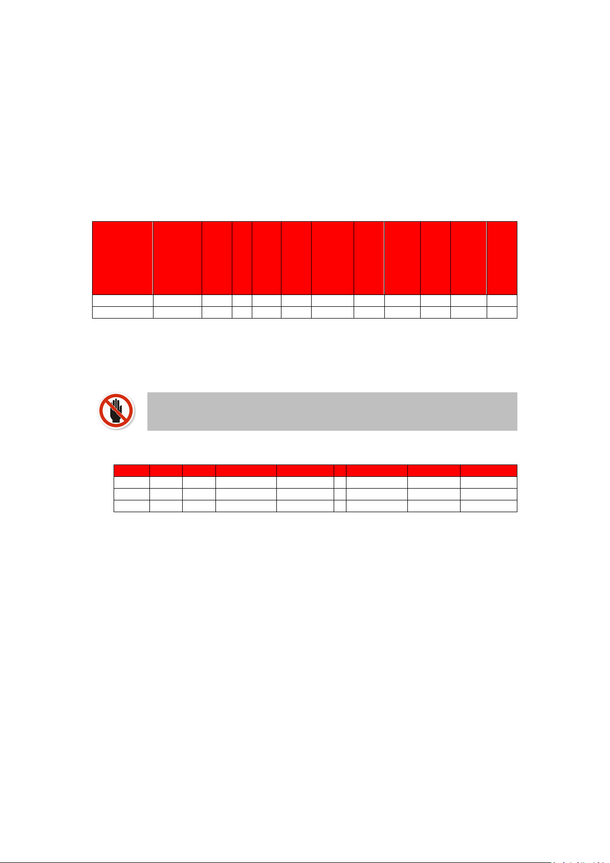
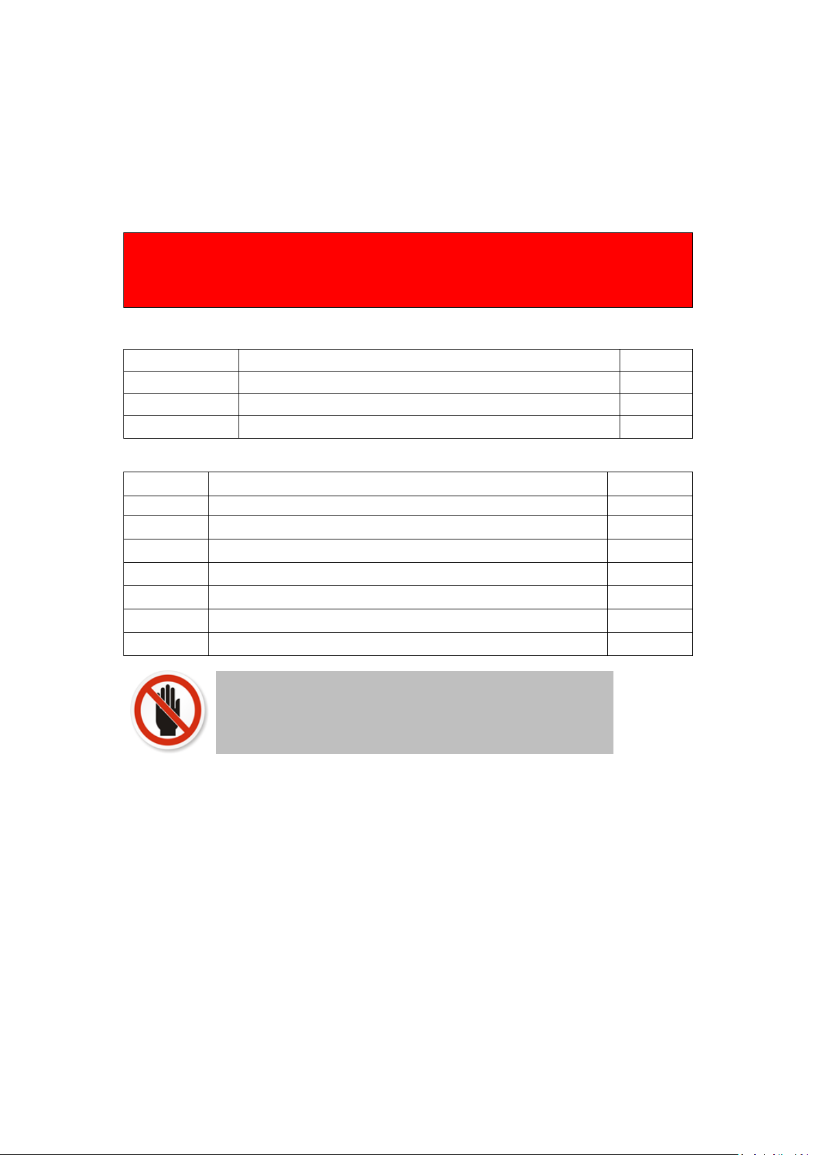
2.1 GENERAL DESCRIPTION OF SAFETY SYMBOLS USED
BANNED
A black symbol inside a red circle with a red diagonal indicates an action that should not be
performed
WARNING
A black symbol added to a yellow triangle with black edges indicates danger
ACTION REQUIRED
A white symbol inserted in a blue circle indicates an action that must be taken to avoid risk
ELECTRICAL HAZARD
Observe all signs placed next to the pictogram. The symbol indicates components of the unit and
actions described in this manual that could create an electrical hazard.
HOT SURFACES
The symbol indicates those components with a high surface temperature that could create a risk.
This symbol shows essential information which is not safety related
Recover or recycle material
8
2.2 WHAT TO DO IF YOU SMELL GAS
Warning if you smell gas
No naked flames, no smoking!
Avoid causing sparks, do not switch on or off electrical equipment or lights
Open windows and doors
Shut off the main gas supply
Warn occupants and leave the building
After leaving the building alert the local gas supply company
Do not re-enter the building until it is safe to do so
Lochinvar Limited is not liable for any damage caused by inaccurately following these installation
instructions. Only original parts may be used when carrying out any repair or service work.
This appliance is not intended for use by persons (including children) with reduced physical,
sensory or mental capabilities, or lack of experience and knowledge, unless they have been given
supervision or instruction concerning use of the appliance by a person responsible for their
safety. Children should be supervised to ensure that they do not play with the appliance.
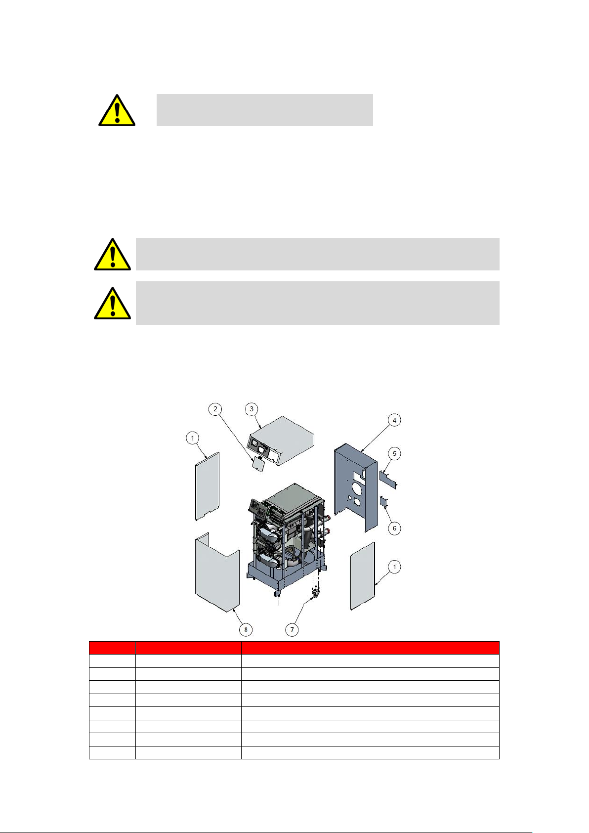
3.0 PRINCIPLE PARTS
3.1 CASING
No
Item No
Description 1 E01-000-124
SIDE PANEL 2 S01-000-337
ELECTRICAL COVER
3
S01-000-380
TOP COVER
4
E01-002-114
REAR COVER
5
E01-002-128
COVER UPPER LIMIT SWITCH
6
E01-002-129
COVER LOWER LIMIT SWITCH
7
S04-000-307
WHEEL ASSEMBLY
8
E01-000-215
FRONT PANEL
9
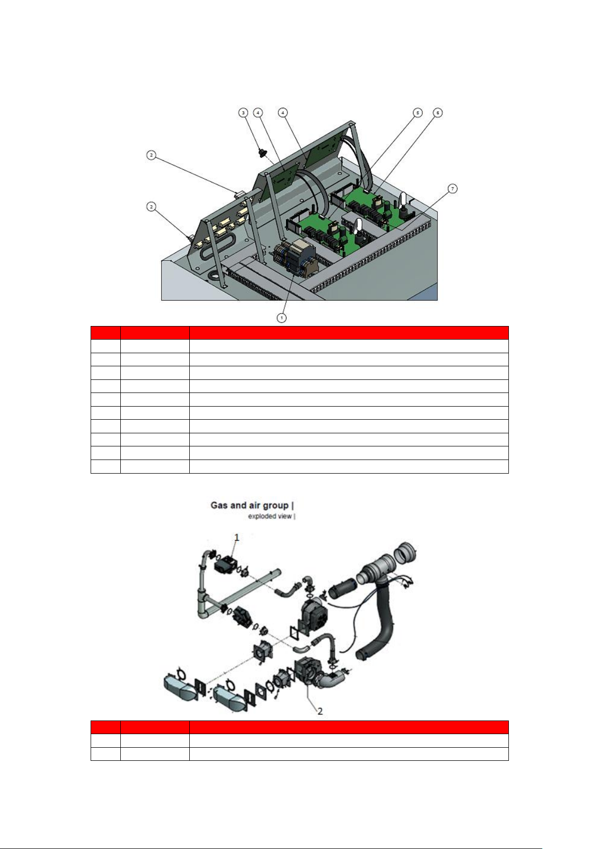
3.2 ELECTRICAL
No
Item No
Description
1
E04-016-425
RELAY LC1D09
2
E04-016-291
CONNECTOR PLUG 2 POLE
2
E04-016-292
CONNECTOR PLUG 3 POLE
2
E04-016-293
CONNECTOR PLUG 4 POLE
2
E04-016-295
CONNECTOR PLUG 6 POLE
3
E05-001-062
RUBBER PLUG 15mm
4
S04-000-310
REPLACEMENT KIT DISPLAY
5 WATER HEATER CONTROL SLAVE-STATE TYPE AND SERIAL NO
6 WATER HEATER CONTROL MASTER-STATE TYPE AND SERIAL NO
7
S04-016-582
FUSE SET x10
3.3 GAS TRAIN AND AIR INLET
No
Item No
Description
1
S04-000-199
GAS VALVE
2
S04-000-200
COMBUSTION FAN

10
4.0 TECHNICAL DATA
Model Number
TTW410
TTW580
GENERAL DATA
Product I.D. Number
CE 0063BS3806
Classification II2H3B/P
Input (gross) min-max
kW
55.4 - 444
75.5 - 611
Input (net) min-max
kW
50 - 400
68 - 550
Recovery Rate (44° ΔT)
l/hr
8168
11263
Recovery Rate (50° ΔT)
l/hr
7188
9912
Heat generator seasonal efficiency
%
95.4
95.9
Shipping Weight
kg
400
450
NOX
mg/kWh
44
41
NOX Class
6
GAS DATA G20
Nominal gas inlet pressure
mbar
20
Maximum gas inlet pressure
mbar
25
Minimum gas inlet pressure
mbar
17.5
Gas flow rate – m3/hr
m3/hr
5.3 - 42.3
7.2 - 58.2
Flue gas mass rate (@ 9.0% CO2)
g/sec
24.1 - 207.8
Gas inlet connection size
“ BSP 2 2
GAS DATA G31
Nominal gas inlet pressure
mbar
37
Maximum gas inlet pressure
mbar
45
Minimum gas inlet pressure
mbar
27
Gas flow rate – m3/hr
m3/hr
16.8
23
Flue gas mass rate (@ 9.0% CO2)
g/sec
193
265
Gas inlet connection size
“ BSP 2 2
ELECTRICAL DATA
Power consumption
W
752
829
Power supply
Single phase 230v/50Hz
Protection class
IPX0B
WATER DATA
Water content
litres
30
43
Water connections (F & R)
“ BSP
2 ½
Max. water pressure
bar 8 8
Min. water pressure
bar 1 1
Maximum water temperature
°C
70
70
4.1.1 TECHNICAL DATA
11
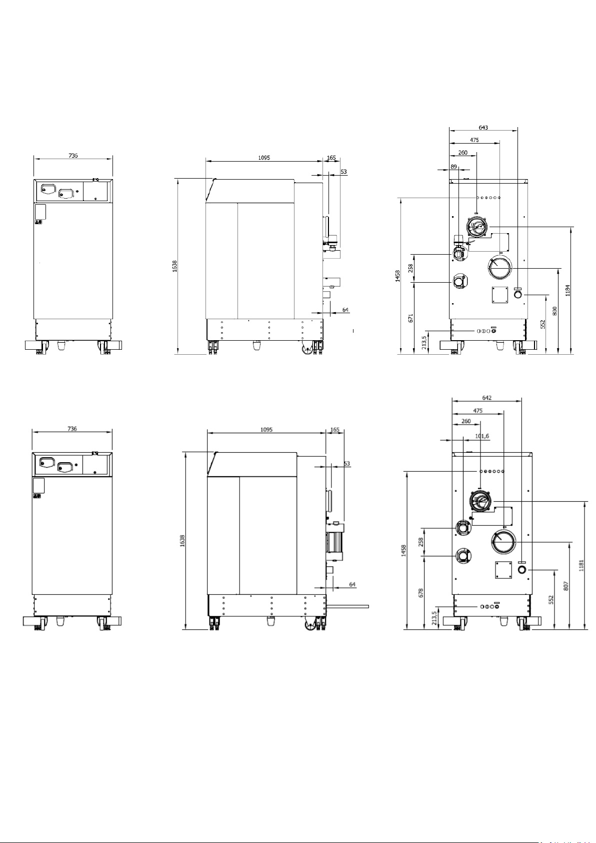
5.0 DIMENSIONS AND CLEARANCE
5.1 DIMENSIONS
5.1.1 DIMENSIONS TTW410
5.1.2 DIMENSIONS TTW580
Minimum Side Clearance of 500mm (Advised 1000mm)
Minimum Front Clearance of 800mm
Minimum Rear Clearance of 500mm
5.1.3 MINIMUM CLEARANCES
12
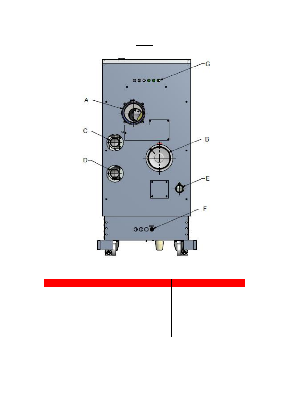
5.2 WATER HEATER CONNECTIONS
Rear view
5.2.1 WATER HEATER CONNECTIONS
Connection
Function
Diameter (inch/mm)
A
combustion air inlet
Ø 180 mm
B
flue outlet
Ø 180 mm
C
water flow (outlet)
R 2½ "
D
water return (inlet)
R 2½ "
E
gas connection
R 2 ”
F
condensate discharge hose
Ø 25 mm outer diameter
G
cable input
Ø 22.5 mm
5.2.2 CONNECTIONS AND CONNECTION SIZES
13
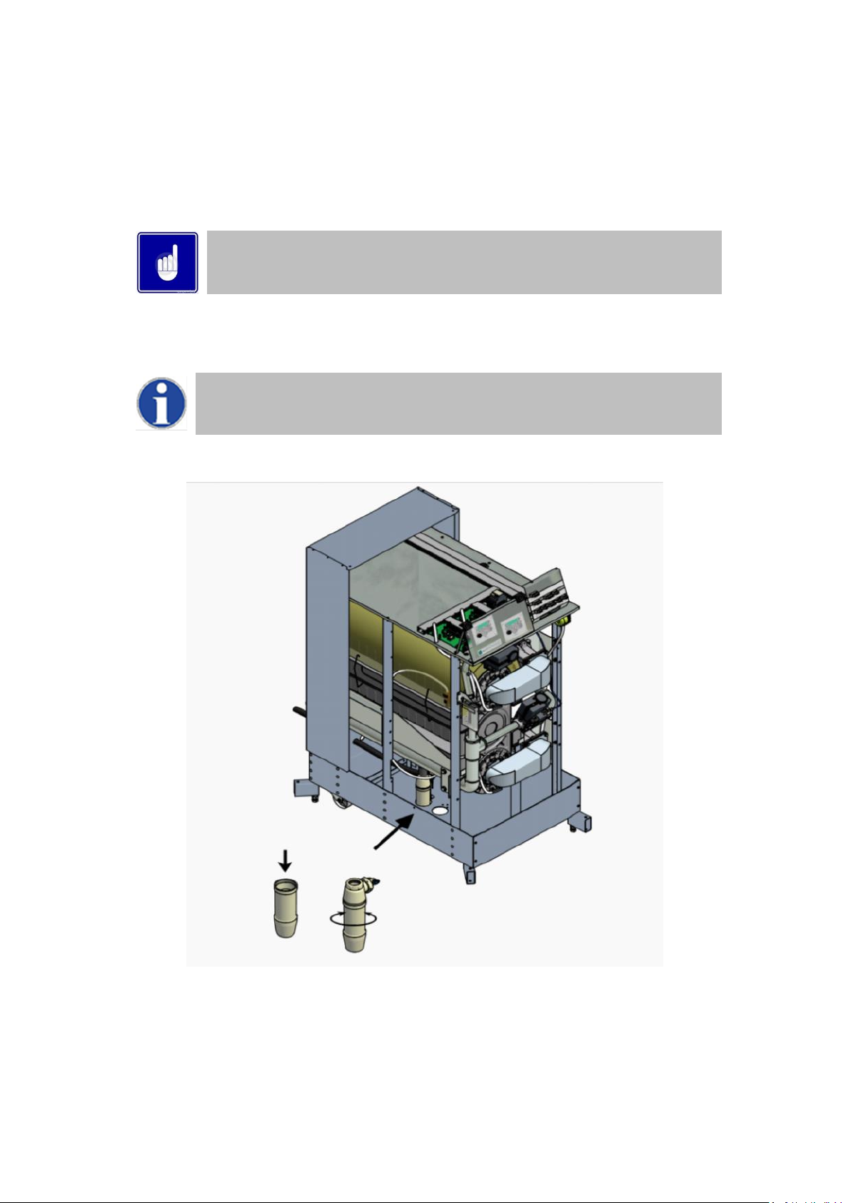
5.3 CONDENSATE DRAIN CONNECTION
The condensate drain is placed at the centre and at the bottom of the water heater and has a ¾ inch hose discharge.
Connect this flexible hose to a suitable drain point.
Use only plastic parts with the condensate drain.
Blockage of this drain may damage the water heater. The drain connection is correct when the condensate can be
seen flowing away.
Any damage caused by incorrectly installing the condensate drain WILL not be covered by
warranty.
There should be an open connection of the condensate hose into the drain. A possible under pressure in the
drainage system must never be allowed to cause drain water to pull into the water heater.
When mounting the bottom part of the siphon, before commissioning the water heater and/or
after maintenance, the siphon must ALWAYS be completely filled with water.
This is a safety measure: the water in the siphon keeps the flue gases from entering the plant
room by leaving the heat exchanger via the condensate drain.
FIGURE 3.2 CONDENSATION SIPHON
Turn LEFT to open
Turn RIGHT to close
Fill with water
to the edge
14
6.0 GENERAL REQUIREMENTS
The Lochinvar TTW comes with the following documents and accessories:
An installation, commissioning and maintenance instruction guide for the installer.
3 spare fuses and 3 spare nuts for the installation of the burner plate (this is attached to the front of the gas
valve).
Spare flue gas plugs
One gas conversion sticker
One Torx key T40
One allen key no. 3
Bottom part of Siphon
Lochinvar will supply a suitable shunt pump with every TTW water heater, this must be
installed with the TTW to maintain the correct flow
On delivery, immediately check that the water heater is complete and without any defects. Report any damage
immediately to Lochinvar Limited.
The Lochinvar TTW has been designed to operate trouble free for many years. These instructions should be
followed closely to obtain the maximum usage and efficiency of the equipment. PLEASE read the instructions fully
before installing or using the appliance.
NOTES
1
All water heaters are supplied as twin pipe model.
2
Using propane, butane and B/P, maximum fan speed
needs to be reduced (parameter P4BD)
3
Below a table is given in which the min. and max. gas
supply pressures are listed according to EN437:
p nominal
[mbar]
p min
[mbar]
p max
[mbar]
G25
25
20
30
G20
20
17
25
G31
30
25
35 37
25
45
G30
50
43
57
4
Emissions measured during unit certification.
5
Maximum combined resistance of flue gas and air
supply piping at high fire.
6
230 Vac is necessary for the water heater to function.
If a 400 Vac water heater pump is applied, 400 Vac
must be connected to the appliance so the power
supply for the pump can be delivered by the system.
(An optional safety switch for the pump motor must be
added externally).

15
6.1 RELATED DOCUMENTS
It is law that all gas appliances are installed by competent persons, in accordance with The Gas Safety (Installation
and Use) Regulations 1998. Failure to install appliances correctly could lead to prosecution. It is in your own
interest, and that of safety, to ensure that this law is complied with.
The installation of the equipment MUST be in accordance with the relevant requirements of the Gas Safety
Regulations, Building Regulations, I.E.E. Regulations and the bylaws of the local water undertaking. The installation
should also be in accordance with any relevant requirements of the local gas distributor and local authority.
In addition the installation should follow the relevant guidance offered in the following documents. It is not
practical to list all relevant information but emphasis is placed on the following documents, as failure to comply
with the guidance given will almost certainly result in an unsatisfactory installation:
Regulation
Description
BS EN 1858: 2008 +
A1: 2011
Chimneys, Components. Concrete flue blocks.
BS 5440-1: 2008
Flueing and ventilation for gas appliances of rated input not exceeding 70 kW net (1st, 2nd and 3rd family
gases). Specification for installation of gas appliances to chimneys and for maintenance of chimneys.
BS 5440-2: 2009
Installation and maintenance of flues and ventilation for gas appliances of rated input not exceeding 70
kW net (1st, 2nd and 3rd family gases). Specification for installation and maintenance of ventilation for gas
appliances.
BS 6644: 2011
Specification for Installation of gas-fired hot water Heaters of rated inputs between 70 kW (net) and 1.8
MW (net) (2nd and 3rd family gases).
BS EN 806 1-5
Specifications for installations inside buildings conveying water for human consumption.
BS 7671 :2008 +
A3:2015
Code of practice for low temperature hot water systems of output greater than 45 kW.
BS 7074: 1989 Parts 1
and 2
Application, selection and installation of expansion vessels and ancillary equipment for sealed systems.
BS 7671: 2008 + A1:
2011
Requirements for electrical installations, I.E.E. wiring regulations seventeenth edition.
BS 7671: Amendment
2: August 2013
BS EN
12828:2012+A1:2014
Heating systems in buildings. Design for water-based heating systems.
CP 342 (Part 2 1974):
Code of practice for centralised hot water supply-buildings other than dwellings.
Institute of Gas Engineers and Managers (IGEM) Publications
IGE/UP/1 - Edition 2:
Installation pipework on industrial and commercial premises.
IGE/UP/2 – Edition 3
Gas installation pipework, boosters and compressors on industrial and commercial premises.
IGE/UP/4 - Edition 4
Commissioning of gas-fired plant on industrial and commercial premises.
IGE/UP/10 - Edition 4
Installation of flued gas appliances in industrial and commercial premises.
Gas Safety (Installation and Use) Regulations 1998 (England, Scotland & Wales)
CIBSE: Guide parts A, B and C
H.S.E. guidance Automatically controlled steam and hot water heaters note PM5:
Third edition of the 1956 Clean Air Act Memorandum on Chimney Heights
Manufacturer's notes must not be taken in any way as overriding statutory obligations.

16
7.0 WATER QUALITY
7.1 WATER CHEMISTRY
Water supply quality may adversely affect the efficiency performance and longevity of Water Heaters and Hot
Water systems. Hard water may cause the formation of limescale that will reduce operating efficiency and may
cause early product failure. Please note the following: -
Maximum allowed water hardness is 205 PPM or 205 mg/L CaCO3 (= 11.5°dH)
TDS (total dissolved solids) may not exceed 350 PPM
Water hardness and TDS together may not exceed 350 PPM
The pH value of the water may not be under 6.5 and not above 7.5 (measured cold)
If TDS alone or the combined value is higher than the abovementioned, the water should be heated by
means of an indirect water-heating appliance.
Minimum water hardness = 80 PPM or 80 mg/L CaCO3 (= 4.5°dH)
Minimum TDS = 100 PPM
Water that is under these minimum values normally has a pH value, which is aggressive and corrosive.
If these values are exceeded a water treatment specialist should be consulted. Water
Softeners and Water Conditioners may be considered, but whichever method is selected, it
should be suitable for installation with Direct Gas-fired Water Heaters. A maintenance
regime will also be required for such systems
The formation of limescale or other solids can cause a blockage within the heat exchanger,
which in turn may cause premature failure. Such instances are not regarded as defects in
manufacture and will not be covered under the product warranty
8.0 LOCATION
8.1 PLANT ROOM REQUIREMENTS
The Lochinvar TTW condensing water heater can only be installed in a room that complies with the appropriate
ventilation requirements.
The Lochinvar TTW can be used as a type C13, C33, C
43, C53,
or C83 appliance. Due to its room sealed design, ventilation
allowances for combustion air are not necessary; ventilation for cooling purposes however, must be fitted. For
further guidance, please refer to Section 9: AIR SUPPLY or to BS6644.
The Lochinvar TTW can also be used as a type B23 appliance. If such a configuration is to be used, then appropriate
ventilation for cooling and combustion must be provided. For further details, please refer to Section 9: AIR SUPPLY
or to BS6644.
8.2 GENERAL REQUIREMENTS
Corrosion of the heat exchanger and vent system may occur if air for combustion contains certain chemical
vapours. Such corrosion may result in poor combustion and create a risk of asphyxiation. Aerosol propellants,
cleaning solvents, refrigerator and air conditioning refrigerants, swimming pool chemicals, calcium and sodium
chloride, waxes and process chemicals are corrosive. Products of this sort should not be stored near the water
heater or outside by the air intake (if applicable). The fitting of this equipment in a situation where aerosols or
other chemicals may be entrained into the combustion air will invalidate the warranty.
The equipment must be installed on a level, non-combustible surface that is capable of adequately supporting its
weight (when filled with water) and any ancillary equipment. The operation of the equipment must not cause the
temperature of any combustible material in the vicinity of the equipment and its flue to exceed 65°C. If such a
situation is unavoidable, appropriate insulation should be provided.
Locate the equipment so that if the appliance or any connecting pipework should leak, water
damage will not occur. When such locations cannot be avoided, it is recommended that a suitable
drain pan be installed under the equipment. The pan should be adequately drained but must not
restrict the combustion or ventilation airflow.

17
8.3 UNPACKING AND LEVELLING THE WATER HEATER
The water heater is mounted on a pallet with a wooden support frame around it. The water heater is wrapped in
shrink wrap before the wooden support frame is mounted. After the frame is placed the whole pallet, water heater
and frame package is shrink wrapped again. Only remove the outer packaging once the water heater has been
positioned as close as possible to the place where it will be installed. After removing the wrapping and frame the
water heater can be taken off the pallet using a fork-lift truck or suitable lifting device. The water heater is fixed to
the pallet with screws; make sure these are removed before attempting to lift the water heater from the pallet.
Once the water heater is in its final position, the inner packaging can be removed.
The water heater will now be stood on 4 adjustment bolts; ensure the water heater is level in both directions by
using these 4 bolts. There are also four legs under the appliance that can be turned outward if a positive fixing to
the floor structure is required.
8.4 CLEARANCES
The location chosen for the equipment must permit the provision for a satisfactory flue system and, where
necessary, an adequate air supply. The location must also provide adequate space for servicing and air circulation
around each unit. This includes any electrical trunking laid across the floor and to the appliance.
See 5.1.3 for dimensions/clearances. Further details regarding locations are given in BS6644.

18
9.0 GAS SUPPLY
The Lochinvar TTW is suitable for use on second and third family gasses 2H - G20 - 20mbar and 3P - G31 - 37mbar.
Details relating to Natural Gas (2H) appear below; for details relating to Propane (3P) please refer to Section 17.1.4
GAS TYPE SELECTION.
9.1 SERVICE PIPES
The local gas distributor must be consulted at the installation planning stage in order to establish the availability
of an adequate supply of gas. An existing service pipe must not be used without prior consultation with the local
gas distributor.
9.2 METERS
The local gas distributor contractor will connect a new gas meter to the service pipe. An existing gas meter should
be checked, preferably by the gas distributor, to ensure that it is adequate to deal with the rate of gas supply
required.
9.3 GAS SUPPLY PIPES
Supply pipes must be fitted in accordance with IGE/UP/2. Pipework from the meter to the equipment must be of
adequate size. The complete installation must be purged and tested as described in IGE/UP/1. Refer to Section
17.1.4 GAS TYPE SELECTION for information on LPG installation guidance.
9.4 BOOSTED SUPPLIES
Where it is necessary to employ a gas pressure booster, the controls must include a low-pressure cut-off switch at
the booster inlet. The local gas distributor must be consulted before a gas pressure booster is fitted. For details
of how to connect a low-pressure cut-off switch, please refer to Section 15.0: ELECTRICAL INSTALLATION.
9.5 PLANT-ROOM CONTROL VALVE
A manual valve for plant-room isolation must be fitted in the gas supply line. It must be clearly identified and
readily accessible for operation, preferably by an exit.
9.6 EQUIPMENT GAS SYSTEM LEAK CHECK
An approved isolating valve and union should be installed for each unit in a convenient and
safe position and be clearly marked.
Ensure that the manual gas service valve is in the OFF position. Although the equipment receives a gas leak check
and gas train component integrity check prior to leaving the factory, transit and installation may cause disturbance
to unions, fittings and components. During commissioning, a further test for tightness should be carried out on
the equipment gas pipework and components.
Care must be taken not to allow leak detection fluid on or near any electrical parts or
connections.

19
10.0 FLUE SYSTEM
All versions of the TTW Condensing water heater can be installed as either type B23 (fan assisted open flue) C53
(room sealed) C63 (Flue not supplied by the appliance manufacturer) appliances. Only B23,C53 Flue systems are
covered in any detail within this document, further information can be found in the TTW Flue assemblies and
ancillaries guide available at www.lochinvar.ltd.uk See the relevant section for details of each flue type and
requirements.
10.1 FLUE SYSTEM GENERAL REQUIREMENTS
Install the horizontal flue components with an angle of 3° back in the direction of the water
heater (roughly equal to five centimetres for every linear meter). Failure to install the flue
correctly will result in a build-up of condense within the flue pipework that will cause early
component failure.
When using a wall terminal, there is the possible risk of ice building-up on surrounding
parts/structures, because the condensate will freeze. This risk should be taken into account
during the design phase of the heating installation.
TTW Water heaters will produce large condense clouds especially during cold weather,
consideration must be taken as to whether this will cause a nuisance to neighbouring properties
and if so alternative flue arrangements used.
TTW Water heaters can operate with very low flue temperatures; as such the flue system used
must be suitable for use with condensing appliances made from either Polypropylene or
stainless steel and have a temperature class of T120.
Aluminium flue pipe must not be used on this appliance as it may lead to premature failure of
the heat exchanger and will invalidate the warranty.
Before installation of any flue system read the installation manual carefully for both the
appliance and flue system to be used. Information on the flue system Supplied by Lochinvar can
be found within this manual.
MODEL NUMBER
TTW410
TTW580
FLUE DATA
Appliance category
B23, C13, C33, C43, C53, C83
Nominal flue diameter – mm
180
180
Maximum flue gas temp. – °C
90
90

20
10.2 FLUE TERMINAL POSITION
Any flue termination must be in such a position as will not cause a hazard to the health of persons who may be
nearby or a nuisance to other persons beyond the curtilage. The flue terminal must be positioned externally such
as to allow the dispersal of products of combustion and air intake. The terminal should be installed in a location
where it will not easily flood or be blocked by snow. Under certain operating and weather conditions, the TTW
may generate a plume at the terminal. Consideration should be given to the nuisance this may cause and the
terminal should be sited accordingly.
The flue terminal position is very important and must be in accordance with the recommendations found in BS6644
or IGE/UP/10. Once the terminal position has been determined the appropriate local authority should be advised
of the proposed installation. It is important that the appropriate local authority is consulted at an early stage in
the design in order to establish that the proposed flue discharge positions are acceptable and will not cause
significant local exceedances of air quality objectives.
Where agreement is reached with the local authority, this should be recorded in a reproducible format as
competent people involved at the latter stages of the project (i.e. the commissioning engineer) will ask for proof
before allowing products of combustion to be discharged in an apparently non-compliant position.
10.3 FLUE GAS AND AIR SUPPLY SYSTEM
The overall resistance of the air supply and exhaust ducts must not create a pressure drop exceeding 200 Pa. The
output of the water heater is influenced by the resistance of the air supply and discharge system therefore all flue
gas and air supply systems must be carefully considered or referred to a specialist flue design company.
Details of air inlet and exhaust locations and sizes can be found in 4.0 TECHNICAL DATA.
10.4 APPROVED FLUE SYSTEM
When used as a type C appliance, the approved, purpose designed adaptive flue system should be used. For further
details, please contact Lochinvar Limited.
When used as a Type B appliance, a suitable flue system constructed of Stainless Steel or Polypropylene with a
temperature rating in excess of 120C should be used.
10.5 INSTALLATION PRECAUTIONS
The water heater must not be operated unless the complete flue system is installed. This
includes the water heater connections, flue pipes, air ducts (if required) and terminals.
Due to the condensing nature of the water heater, long external runs should be avoided to
prevent the condensate freezing within the flue system.
During assembly, precaution should be taken to ensure that any sealing ring is seated
correctly
Due to the close tolerances in the flue system, it may be necessary to use a twisting action
to fit the joints together. No lubrication other than water should be used.
21
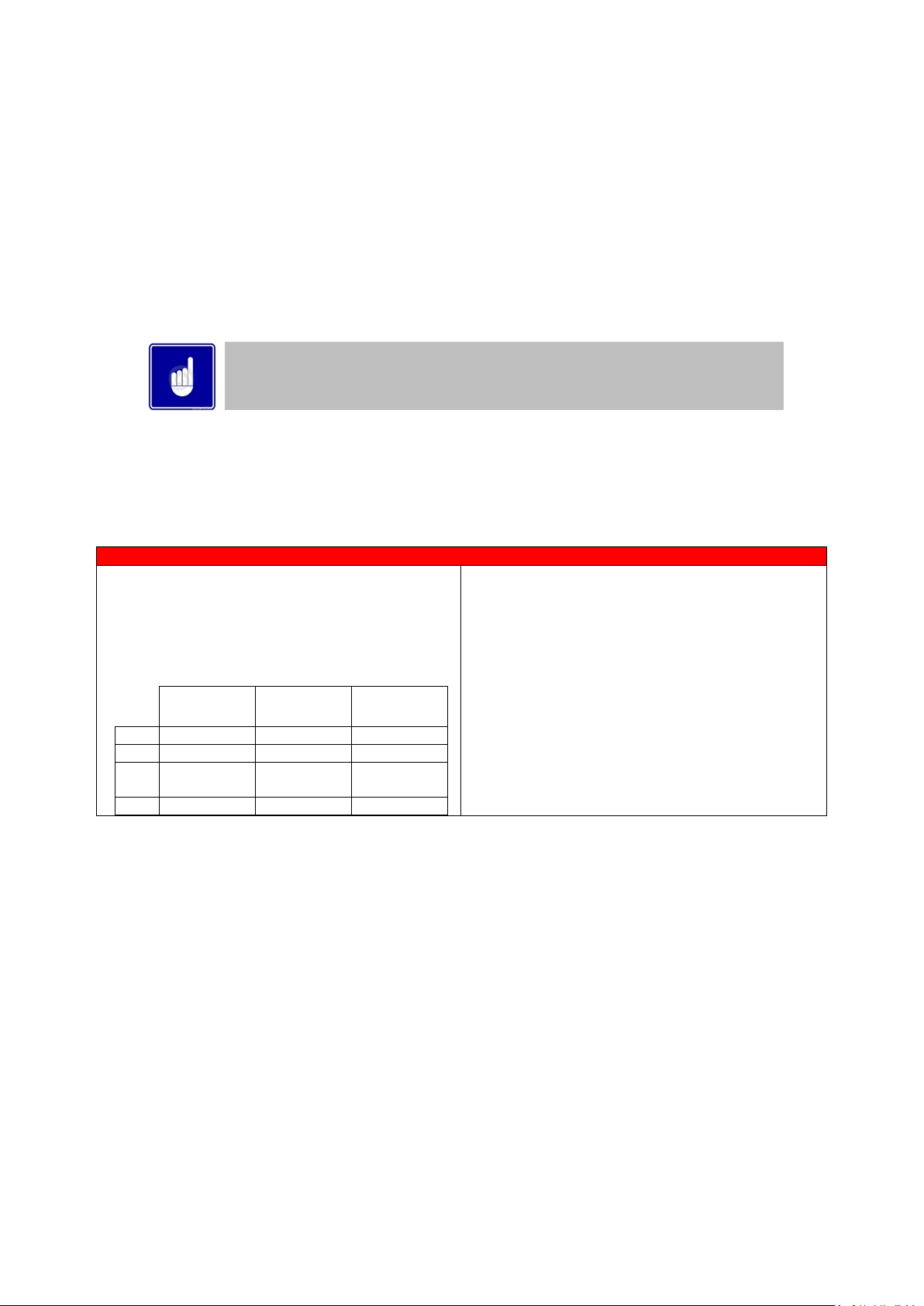
10.6 WATER HEATER CATEGORIES - TYPES OF FLUE GAS SYSTEMS.
Type according EN 15502-2-1: 2012
Performance
Description
B23(P)
Open
Air supply from
room
* Roof terminal
* Without draught diverter
* Water heater room air supply.
* P = overpressure systems
Be aware: The installation room has to have sufficient air
supply vents. These vents must be open and
may not be closed or blocked.
Requirements at NEN 3028 paragraph 6.5
Use table 10.11 to select the correct flue items.
C53 Closed
Air supply from
outside
*Separate air supply duct
*Separate flue gas discharge duct.
* Air supply inlet and flue gas outlet at different air
pressure zones. But not at opposite walls.
Use table 10.9 to select the correct flue items
Flue
Outlet
Air
Inlet
Flue
outlet
Air
inlet
Vented
area
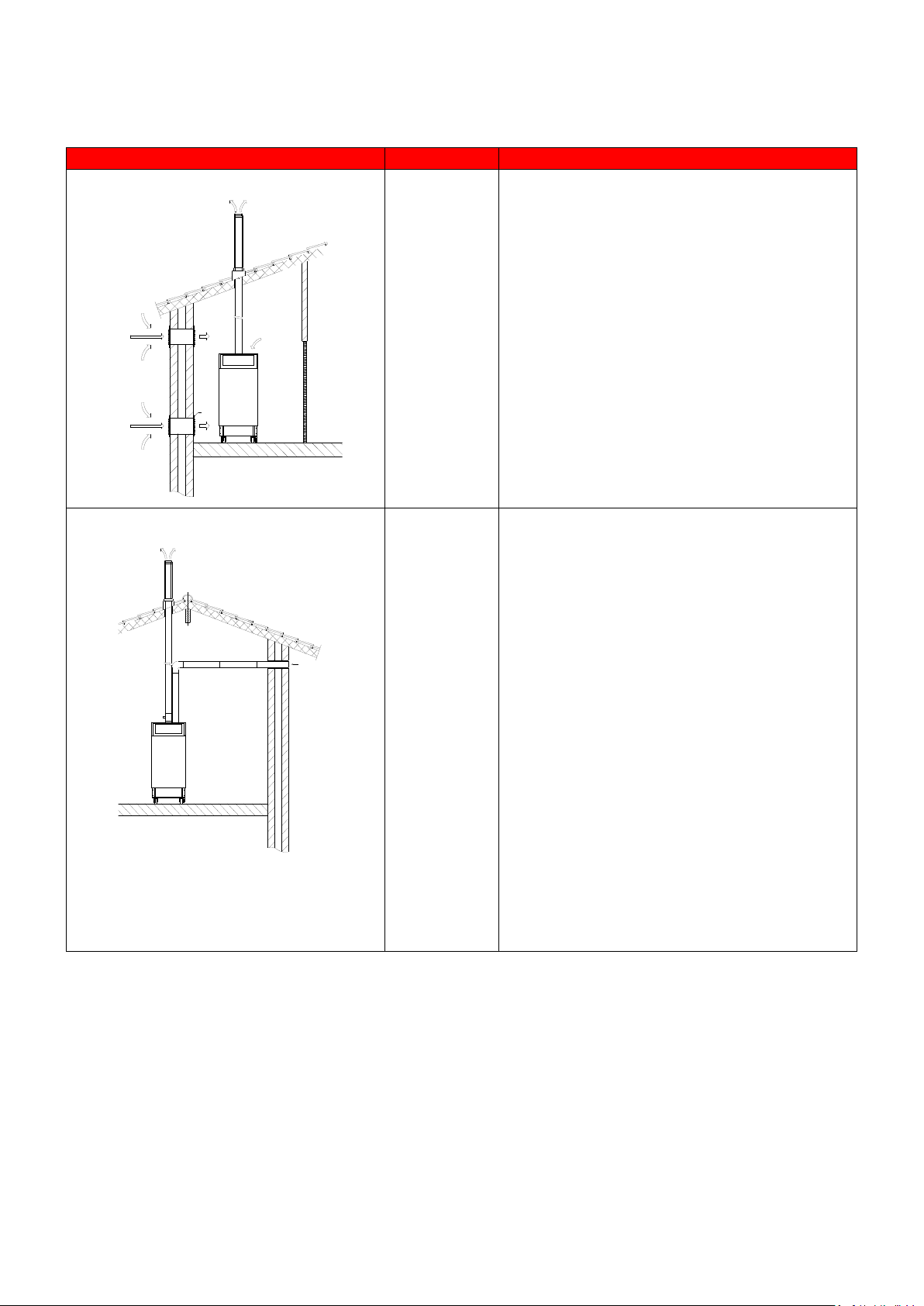
22
C63 Closed
Air supply from
outside
* Appliance sold without flue/air-inlet ducts
* The flue gas parts are not part of the water heater. The
water heater is intended to be connected to a separately
approved and marketed system for the supply of
combustion air and discharge of combustion products.
Condensate is allowed to go to the water heater.
* Air supply inlet and flue gas outlet not at opposite walls
* Technical data:
nominal T
flue gas
85°C
nominal Q
fluegas
see 2.2
1)
maximum T
fluegas
95°C
min. load T
fluegas
35°C
min. load Q
fluegas
see 2.21)
nominal % CO2
see 2.21)
max. allowed draft
70Pa
max. pressure drop inlet-
outlet
200Pa
max T
air supply
40°C
max recirculation
10%
1) table technical specifications
See chapter: Accessories
- Fluegas and air supply parts
Flue outlet
Air inlet
23
10.7 TYPE C
63
CERTIFIED
In general, water heaters are certified with their own flue gas material. For type B23(P), C13, C33, C43, C53 and
C83 systems, only use flue gas and air supply parts approved for use with the appliance.
If a heater is C63 certified, no specific type flue gas material has been certified in combination with the water
heater. In this case the flue gas and air supply parts should comply with the applicable European standards
(EN14989).
So, for type C63 systems flue gas and air supply parts from other suppliers can be used. It must be able to handle
the condensate forming (W) and transport, overpressure (P1) and must have a minimum temperature class of
T120. Also, it has to meet the requirements in the following chapters "air supply" and "flue terminal".
CE string
flue gas
material
European standard
Temperature
class
Pressure class Resistance to
condensate
Corrosion
resistance class Metal: liner
specifications
Soot fire resis-tance class
Distance to
combustible
material
Plastics:
location Plastics: fire
behaviour
Plastics:
enclosure
min. req. PP
EN 14471
T120
P1 W 1 O
30
I of E
C/E
L
min. req. SS
EN 1856-1
T120
P1 W 1
L20040
O
40
A few examples of flue gas material suitable for TTB water heaters:
CE String for Plastic PPs: EN14471 T120 P1 W 2 O(30) I C/E L
CE String for Stainless Steel: EN1856-1 T250 P1 W V2-L50040 O (50)
When selecting flue gas systems, be aware that the minimum requirements are met. So only select flue gas
materials having the same or better properties than this table.
Never use aluminium containing flue gas pipes in these water heaters.
Connecting diameters and tolerances:
mat d
nom
D
outside
L
insert
d
inside
L
insert
d
wall thickness
RVS 180
180 ± 0,3
50 ± 1
181,2 ± 0,3
50 +0/ -2
0,6 ± 10%
RVS 200
200 ± 0,3
50 ± 1
201,2 ± 0,3
50 +0/ -2
0,6 ± 10%
PP 200
200 +1/ -0,6
50 +20/ -2
202 +0,6/ -1
50 +20/ -2
≥ 3,5
Multiple water heaters can be connected to a common duct. These flue gas systems for multiple water heater
installations must always be engineered as zero or negative pressure systems; so as to prevent the risk of
recirculation of the flue gases. Consult the flue gas supplier for detailed information and engineering.
If the combustion air is taken from the water heater room, the inlet air must be clean and free of water. Always
use a wire mesh to prevent debris being drawn into the air inlet
10.8 TTW AIR INLET / FLUE GAS OUTLET CALCULATION EXAMPLES
The load of the water heater is influenced by the resistance of the air supply and the discharge system. The
diameter and length of both air supply and flue gas pipes needs to be designed accurately to decrease the possible
power loss of the water heater.
Calculation examples
In the following, two calculation examples are given for determining the maximum length of the flue gas and air
supply pipes.
A: Twin pipe system with separate pipes for flue gas and air supply.
Air supply roof mounted.
B: Single pipe system for flue gas outlet only.
Air supply from water heater room.
24
10.9 TYPE C
53
(TWIN PIPE) FLUE SYSTEMS
Flue system specifications
MANUFACTURER MUELINK AND GROL (M&G)
TEMPERATURE CLASS T120
FLUE GAS MATERIAL PP
Each Twin-Pipe starter assembly includes the items shown in the tables below
TWIN-PIPE FLUE ASSEMBLY MODELS
TTW410,TTW580
COMPONENTS REQUIRED TO START INSTALLATION
VERTICAL FLUE
M70439
VERTICAL TERMINAL Ø200mm
1
LE400092
INCREASER Ø180mm TO Ø200mm FOR AIR INLET ONLY
1
LE400093
ECCENTRIC INCREASER Ø180mm - Ø200mm FOR EXHAUST
1
LE400096
VERTICAL TERMINALØ200mm (AIR INLET) - PP
1
Additional Flue Ancillary Items
Item No.
Description
Dimensions
LV310696
EXTENSION Ø200mm PP
500mm
M70402
EXTENSION Ø200mm PP
1000mm
M70404
EXTENSION Ø200mm PP
2000mm
M70411
ELBOW 90° Ø200mm PP
n/a
M70412
BEND 45° Ø200mm PP
n/a
LV310677
T PIECE WITH CONDENSATE CONNECTOR Ø200mm PP
n/a
M87198
WALL CLAMP Ø200mm
n/a
Do not reduce the pipe diameter relative to the water heater connection
25
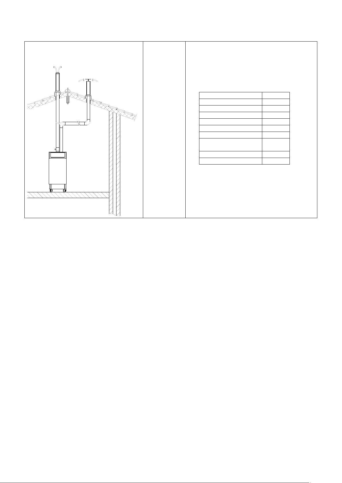
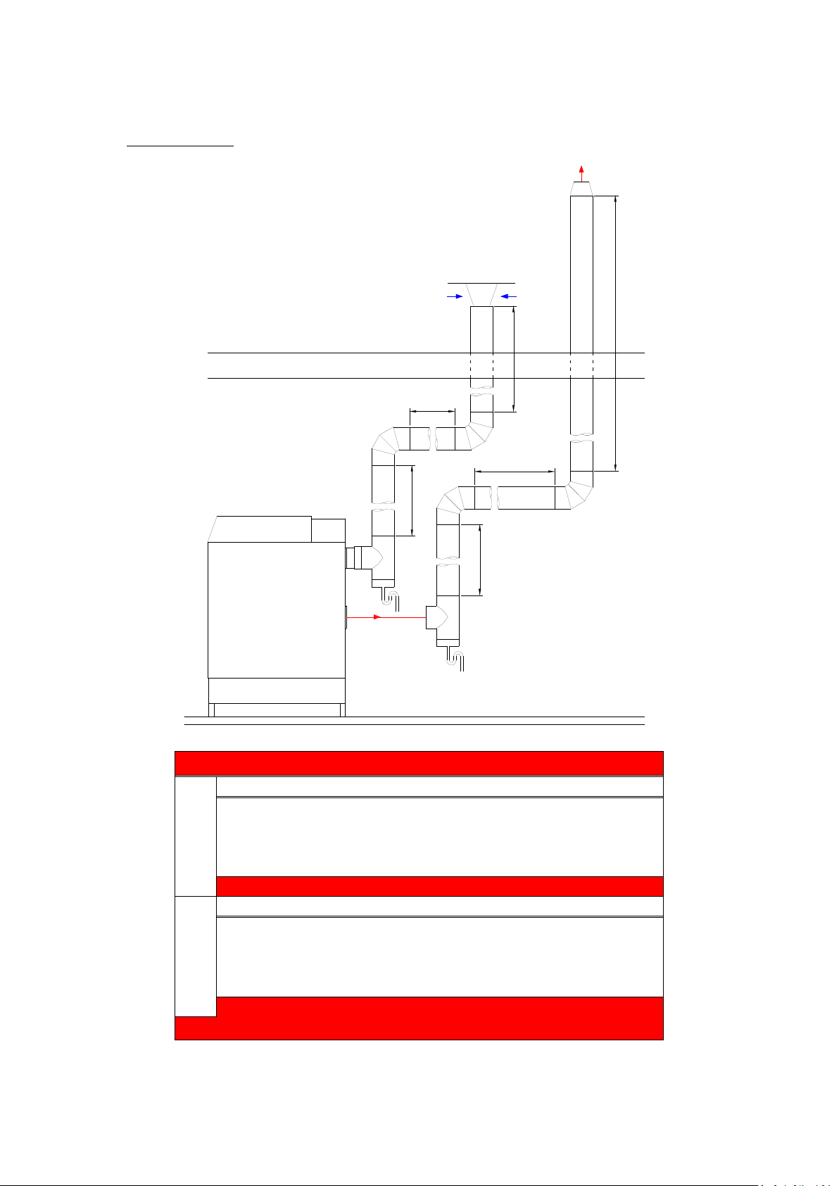
10.9.1 EXAMPLE A: TWIN PIPE SYSTEM
Calculation example:
The total resistance is less than 200 Pa, so this is acceptable.
Water heater type:
TTW410
Flue gas
Diameter: 200 mm.
Number
Pa
Pa total
Straight tube m¹
total
13
1,8
23,4
T-piece
outlet 1 16,7
16,7
Bend
90° 2 6,5
13
Flue outlet
Zeta=0,05
1
0,9
0,9
Total resistance flue gas outlet:
54,0
Air supply
Diameter: 200 mm.
Number
Pa
Pa total
Straight tube m¹
total 7 1,3
9,1
T-piece
inlet 1 17,5
17,5
Bend
90° 2 4,9
9,8
Air inlet
Zeta=1,0 1 14,0
14,0
Total resistance air supply:
50,4
Total resistance flue gas outlet and air supply:
104,4 Pa
INLET AIR MUST BE CLEAN
AND FREE OF WATER.
USE A WIRE MESH WHEN
THERE IS RISK OF DEBRIS
BEING DRAWN INTO THE
AIR INLET.
EXAMPLE A
8m
3m
1m
2m
2m
4m
INLET AIR MUST BE CLEAN
AND FREE OF WATER.
ALWAYS USE A WIRE MESH
TO PREVENT DEBRIS BEING
DRAWN INTO THE AIR INLET.
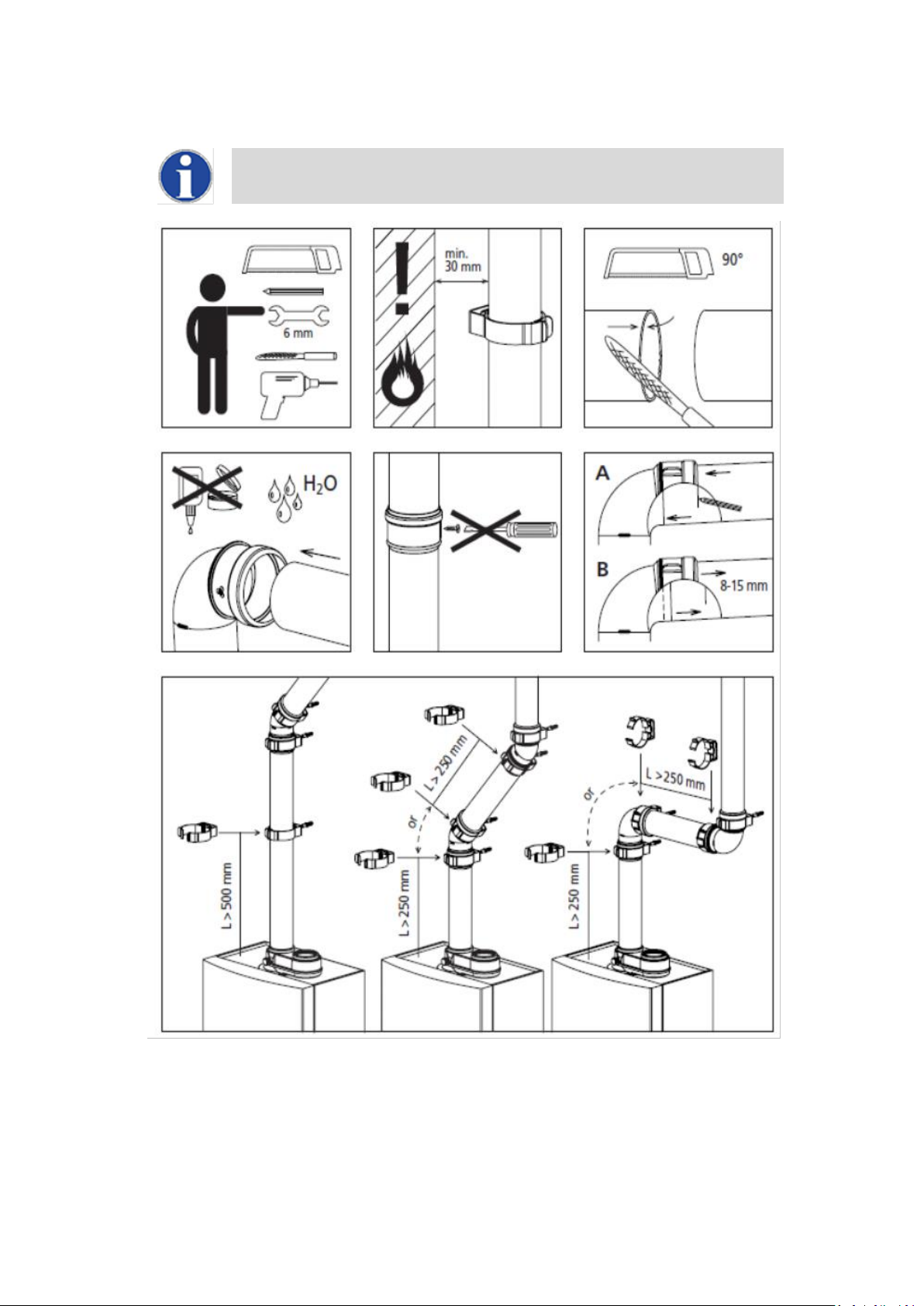
26
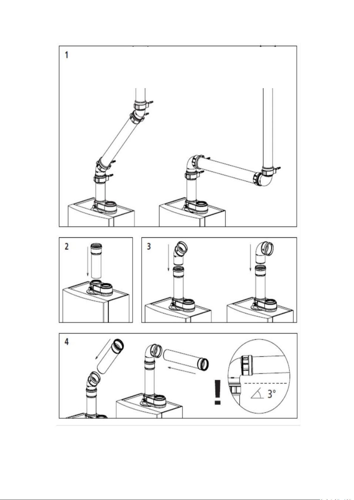
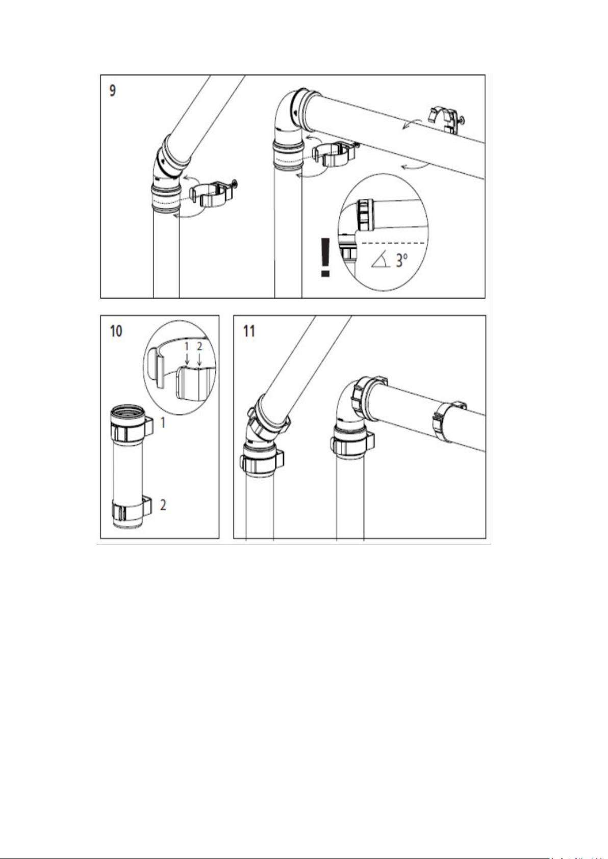
10.10 GENERAL TWIN-PIPE INSTALLATION GUIDELINES
The images shown below may not represent the equipment supplied, images and
instructions are for general guidance only
27
28

29
10.11 TYPE B
23
(CONVENTIONAL FLUE WITH FAN ASSISTANCE)
When the water heater is installed as a Type B23 appliance, the flue system should be installed in accordance with
the flue manufacturer’s specific instructions
CONVENTIONAL FLUE ASSEMBLY MODELS
TTW410,TTW580
COMPONENTS REQUIRED TO START INSTALLATION
Item No.
Description
Dimensions
M70439B
VERTICAL TERMINAL Ø200mm
1
LE400093B
ECCENTRIC INCREASER Ø180mm - Ø200mm FOR EXHAUST
1
LE400094B
AIR INLET SCREEN Ø160mm SS
1
Additional Flue Ancillary Items
Item No.
Description
Dimensions
LV310696
EXTENSION Ø200mm PP
500mm
M70402
EXTENSION Ø200mm PP
1000mm
M70404
EXTENSION Ø200mm PP
2000mm
M70411
ELBOW 90° Ø200mm PP
n/a
M70412
BEND 45° Ø200mm PP
n/a
LV310677
T PIECE WITH CONDENSATE CONNECTOR Ø200mm PP
n/a
M87198
WALL CLAMP Ø200mm
n/a
When using flue pipe supplied by Lochinvar the guidance given in section 10.10 is also applicable for B23
systems.
30
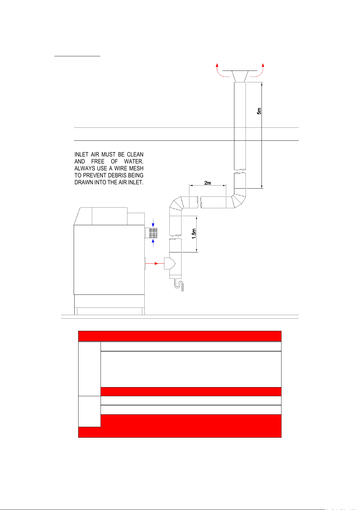
10.11.1 EXAMPLE B: SINGLE PIPE SYSTEM FOR FLUE GAS OUTLET ONLY
Calculation example:
The total resistance is less than 200 Pa, so this is acceptable.
Water heater type:
TTW410
Flue gas
Diameter: 180 mm.
Number
Pa
Pa total
Straight tube m¹
total
8,5
3,0
25,5
T-piece
outlet 1 25,5
25,5
Bend
90° 2 9,9
19,8
Flue outlet
Zeta=1,0
1
28,3
28,3
Total resistance flue gas outlet:
99,1
Air supply
Diameter: 180 mm.
Number
Pa
Pa total
Air inlet
Zeta=1,3
1
27,7
27,7
Total resistance air supply:
27,7
Total resistance flue gas outlet and air supply:
126,8 Pa
INLET AIR MUST BE CLEAN
AND FREE OF WATER.
ALWAYS USE A WIRE MESH
TO PREVENT DEBRIS BEING
DRAWN INTO THE AIR INLET.
 Loading...