

Page 1
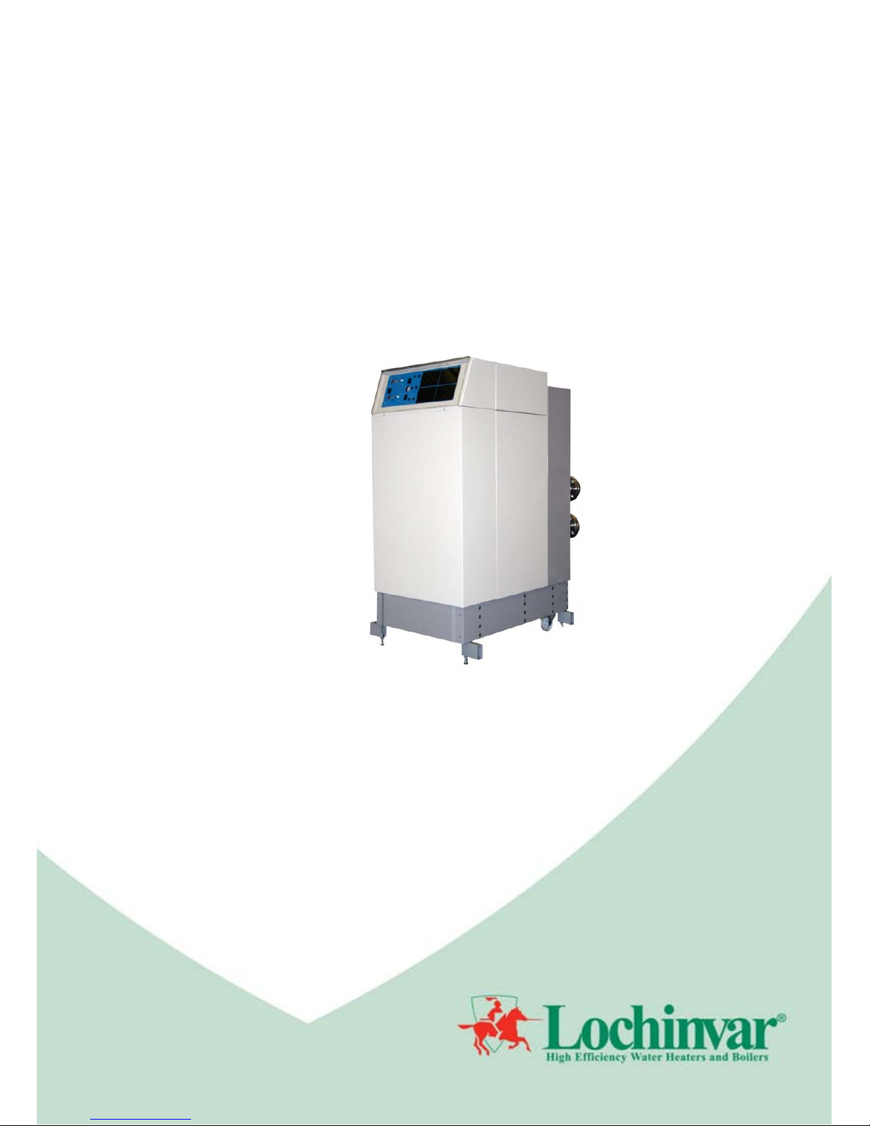
The TTB range
High Efficiency Gas Fired Condensing Boiler
User Instructions
Models:
TTB410
TTB580
INS0043 Issue No 1 | April 2013
Page 2

2
Page 3

3
1.0 DISPLAY CODES .......................................................................................................................................................................................................................... 4
1.1 DOUBLE NUMBERS ............................................................................................................................................................................................................. 4
1.2 DIAGNOSTIC CODES ........................................................................................................................................................................................................... 4
1.3 ERROR CODES .................................................................................................................................................................................................................... 4
2.0 USER GUIDE ................................................................................................................................................................................................................................. 5
2.1 GENERAL REQUIREMENTS ................................................................................................................................................................................................ 5
2.2 PROCEDURE FOR LIGHTING ............................................................................................................................................................................................. 5
2.3 PROCEDURE FOR SHUTTING DOWN ............................................................................................................................................................................... 5
2.4 TEMPERATURE ADJUSTMENT PROCEDURE .................................................................................................................................................................. 5
2.5 MAINTENANCE ..................................................................................................................................................................................................................... 5
2.6 FROST PROTECTION .......................................................................................................................................................................................................... 6
2.7 AIR SUPPLY .......................................................................................................................................................................................................................... 6
2.8 CONDENSATE DRAIN .......................................................................................................................................................................................................... 6
3.0 WARRANTY .................................................................................................................................................................................................................................. 6
Page 4

4
1.0 DISPLAY CODES
The Lochinvar TTB has two three digit LED display on the front panel; these displays are used for setting the
desired stored water temperature and for aiding diagnosis if the unit is not firing.
1.1 DOUBLE NUMBERS
If two numbers (e.g. 80) are displayed on the upper display, the water heater is operating normally and the value
displayed is the setpoint of the water heater. If two numbers (e.g. 80) are displayed on the lower display, the lower
burner has a demand present and the value displayed is the setpoint for the burner. If the green LED below either
display is illuminated, this signifies that the relevant burner is active.
1.2 DIAGNOSTIC CODES
When a code is permanently displayed (i.e. not flashing), on the upper or lower display, the relevant burner is
waiting for a specific condition before beginning the firing sequence. The following table gives a list of diagnostic
codes, descriptions of the fault and solutions.
Code
Fault
Solution
A1
System pressure too low
Check system pressure
A2
Outlet temper ature too high
Wait for outlet temperature to drop
A3
External sens or temperature too high
Wait for temperature to drop
A5
Anti-cycling time
Wait for time period to expire
A6
Fan speed too high
Wait for fan speed to drop
A7
Fan speed too low
Wait for fan speed to increase
A8
Water flow through heater too low
Wait for water flow to increase
C1
Flame simulat ion
Wait for burn er to extinguish
C3
High limit thermostat activated
Wait for water temperature to drop
E6
Heater runni ng in safe operation mode
Contact qualified serv ice personnel
TABLE 1.1 DIAGNOSTIC CODES
1.3 ERROR CODES
When a code is flashing in the upper or lower LED display, the relevant burner has locked out and will need to be
reset by depressing the button on the water heater control panel. The following table gives a list of error codes,
descriptions of the causes. If an error code does not reset or occurs again immediately, a competent person
should be called to investigate and rectify the fault.
Code
Fault
F0
Short circui t in ionisation circuit
F1
Blocked condensate drain
F2
High temperature limit exceeded
F4
Wrong fan speed
F5
No flame after 5 ignition attempts
F6
Flame lost (4 times) during running
E0
Outlet temperature sensor shorted or inter rupted
E2
Inlet temperature sensor shorted or interrupted
E5
Flow temperature sensor shorted or interrupted
E6
Low water flow (A8) has occurred 4 tim es
PP
Parameters programmed into contr oller
PE
Incorrect parameters programmed i nto controller
nc
Heater contr ol has failed
NC
Cascade communication has failed
H1
Gas valve wiring interrupted
TABLE 1.2 ERROR CODES
Page 5

5
2.0 USER GUIDE
2.1 GENERAL REQUIREMENTS
This equipment must be installed by a competent person, registered with a H.S.E. approved
body. All installations must conform to the relevant Gas Safety and Building regulations. Health
& safety requirements must also be taken into account when installing any equipment.
A competent person must also undertake any alterations that require the gas train or flue system
to be broken.
Any interference with a sealed component is forbidden.
Failure to comply with the above may lead to prosecution.
Incorrect use may result in injury and will also invalidate the warranty
2.2 PROCEDURE FOR LIGHTING
1. Ensure that the gas inlet appliance isolating valve is in the “off” position.
2. Press the power rocker switch, positioned on the front of the appliance next to the control thermostat, to
bring the equipment on.
3. The combustion fans should ramp up to full speed to purge the combustion chamber and then drop back
to half rate in order to light. As the gas inlet appliance isolating valve is closed, the controls should go to
a flame failure condition after four ignition attempts.
4. If the above occurs correctly, open the gas inlet appliance isolating valve and reset the unit by
depressing the button on both upper and lower control panels.
5. The combustion fans will repeat the pre-purge procedure and attempt to light. Once a flame is
established, the green ‘Burner On’ lamp, located below the digital display on the control panel, will
illuminate for each burner.
2.3 PROCEDURE FOR SHUTTING DOWN
To take the appliance out of service, the control thumbwheel on the upper display should be set to its minimum
value. If the appliance is operati ng when the thumbwheel is turned, wait for a period of 60 secon ds to allow the
appliance to complete its combustion cycle. Once the appliance is in its standby mode, the main power rocker
switch can be turned to the off position. If the appliance in to be shut do wn for a long period of time, the gas
supply should be isolated at the gas inlet appliance isolating valve.
2.4 TEMPERATURE ADJUSTMENT PROCEDURE
The operating temperature of the boiler can be adjusted using the thumbwheel on the upper display of the
appliance control panel. The LED display on the panel will change to show the selected set point temperature.
2.5 MAINTENANCE
Service intervals should be determined during the first months of operation. Details of this procedure can be found
in the Installation Commissioning and Maintenance Instructions for the appliance. If these instructions are not
available, a copy should be obtained from Lochinvar’s website
www.lochinvar.ltd.uk.
Even if the maintenance schedule for the storage vessel is determined to be less than annually, it is
important that all controls and safety features are checked for correct operation on an annual basis.
A competent person should check and ensure that the flue system, ventilation to the plant room, safety valve,
drain, pressure gauge etc. are in a serviceable and working condition and still comply with the relevant standards
and codes of practice, as detailed in the Installation, Commissioning and Maintenance Instructions.
Page 6

6
2.6 FROST PROTECTION
If the temperature of the water at the inlet side of the heat exchanger drops below 5°C, the primary pump will be
energised. If the temperature of the water at the inlet side of the heat exchanger drops further and reaches 3°C
the burner will fire. If the temperature rises above 10°C the burner and the pump will shut down.
2.7 AIR SUPPLY
When installed as a conventionally flued appliance, the room in which the appliance is installed must be
ventilated.
Blocking these air vents may lead to severe injury, serious property damage or death.
The area in which the appliance is installed should not be used to store any other materials.
2.8 CONDEN SATE DRAIN
The condensate drain must not be blocked or modified in any way. If fitted with a neutralisation kit, this must be
replaced at least every 12 months to ensure correct operation. Due to its design, no further maintenance should
be necessary.
3.0 WARRANTY
Full warranty terms and conditions are available at
www.lochinvar.ltd.uk
Page 7

7
NOTES
NOTES
__________________________________________________________________________________
__________________________________________________________________________________
__________________________________________________________________________________
__________________________________________________________________________________
__________________________________________________________________________________
__________________________________________________________________________________
__________________________________________________________________________________
__________________________________________________________________________________
__________________________________________________________________________________
__________________________________________________________________________________
__________________________________________________________________________________
__________________________________________________________________________________
__________________________________________________________________________________
__________________________________________________________________________________
__________________________________________________________________________________
__________________________________________________________________________________
__________________________________________________________________________________
__________________________________________________________________________________
__________________________________________________________________________________
__________________________________________________________________________________
__________________________________________________________________________________
__________________________________________________________________________________
__________________________________________________________________________________
__________________________________________________________________________________
__________________________________________________________________________________
__________________________________________________________________________________
__________________________________________________________________________________
__________________________________________________________________________________
__________________________________________________________________________________
__________________________________________________________________________________
Page 8

 Loading...