

Lochinvar TISUN SCH-I-O, TiSUN SCH065, TiSUN SCH090, TiSUN SCH110, TiSUN SCH130 Operation Manual
Page 1

SCH-I-O Rev A
Installation & Operation
Manual
SCH Collectors
WARNING:
This manual must only be used by a qualified heating
installer/service technician. Read all instructions
before installing. Perform steps in the order given.
Failure to comply could result in severe personal
injury, death, or substantial property damage.
Page 2

Contents
HAZARD DEFINITIONS . . . . . . . . . . . . . . . . . . . . . . . . . . 2
1. INTRODUCTION . . . . . . . . . . . . . . . . . . . . . . . . . . . . 3-6
Technical Data . . . . . . . . . . . . . . . . . . . . . . . . . . . . . . . . . . 3
How It Works . . . . . . . . . . . . . . . . . . . . . . . . . . . . . . . . . . . 4
Components . . . . . . . . . . . . . . . . . . . . . . . . . . . . . . . . . . . . 4
Descriptions . . . . . . . . . . . . . . . . . . . . . . . . . . . . . . . . . . . . 4
2. LOCATION
Array Options . . . . . . . . . . . . . . . . . . . . . . . . . . . . . . . . . . . 7
Installation Positions . . . . . . . . . . . . . . . . . . . . . . . . . . . . . 8
Handling and Storing . . . . . . . . . . . . . . . . . . . . . . . . . . . . . 9
What to Avoid . . . . . . . . . . . . . . . . . . . . . . . . . . . . . . . . . . . 9
3. ROOF ATTACHMENT INSTALLATION
Roof Attachment Types . . . . . . . . . . . . . . . . . . . . . . . . . . 10
Roof Attachment Quantities for SCH Collectors . . . . . . . 11
Roof Attachment Spacing Distance . . . . . . . . . . . . . . . . . 12
Installation of Roof Attachment Types . . . . . . . . . . . . 13-27
4. COLLECTION INSTALLATION
Horizontal Bar Lengths . . . . . . . . . . . . . . . . . . . . . . . . . . . 28
Spacing Information . . . . . . . . . . . . . . . . . . . . . . . . . . . . . 28
SCH Parallel Mounting Instructions . . . . . . . . . . . . . . 29-31
SCH Inclined / Non-South Facing Mounting Instructions 32-34
SCH Frame Dimensions . . . . . . . . . . . . . . . . . . . . . . . . . 35
SCH Mounting Hardware + Hydraulic Connection Kits . . 36
5. HYDRAULIC CONNECTIONS
SCH Connections Kits . . . . . . . . . . . . . . . . . . . . . . . . . . . 37
Hydraulic Expansion Kits . . . . . . . . . . . . . . . . . . . . . . 37-38
Pressure Drop Chart . . . . . . . . . . . . . . . . . . . . . . . . . . . . 39
6. SYSTEM STARTUP
Startup . . . . . . . . . . . . . . . . . . . . . . . . . . . . . . . . . . . . . . . 40
Filling, Flushing and Bleeding . . . . . . . . . . . . . . . . . . . . . 40
Clamp Ring Screw Connections . . . . . . . . . . . . . . . . . . . 41
Flat Seal Screw Connections . . . . . . . . . . . . . . . . . . . . . . 41
Operation, Multi-function Ball Valve & Check Valve . . . . 41
7. MAINTENANCE
Fluid Installation . . . . . . . . . . . . . . . . . . . . . . . . . . . . . . . . 42
System Design Considerations . . . . . . . . . . . . . . . . . . . . 42
Technical Data . . . . . . . . . . . . . . . . . . . . . . . . . . . . . . . . . 42
Solar Circuit . . . . . . . . . . . . . . . . . . . . . . . . . . . . . . . . . . . 43
Collector . . . . . . . . . . . . . . . . . . . . . . . . . . . . . . . . . . . . . . 43
Pump / Control Function . . . . . . . . . . . . . . . . . . . . . . . . . 43
Control Settings . . . . . . . . . . . . . . . . . . . . . . . . . . . . . . . . 43
Revision Notes . . . . . . . . . . . . . . . . . . . . . . . . . Back Cover
Hazard definitions
The following defined terms are used throughout this manual to bring attention to the presence of hazards of various risk levels or
to important information concerning the life of the product.
DANGER
WARNING
CAUTION
CAUTION
NOTICE
DANGER indicates an imminently hazardous situation which, if not avoided, will result in death or serious
injury.
WARNING indicates a potentially hazardous situation which, if not avoided, could result in death or serious
injury.
CAUTION indicates a potentially hazardous situation which, if not avoided, may result in minor or moderate
injury.
CAUTION used without the safety alert symbol indicates a potentially hazardous situation which, if not
avoided, may result in property damage.
NOTICE indicates special instructions on installation, operation, or maintenance that are important but not
related to personal injury or property damage.
2
Page 3
1 Introduction
SCH Collectors Installation & Operation Manual
The SCH collector is suitable for parallel installations and inclined installations on pitched and flat roofs as well as freestanding
on the ground. It is available as a single-piece large collector in sizes ranging from 65 to 130 ft
2
with inlet and outlet connections of
.86" in diameter. Suitable mounting systems are available for various types of roofing. The SCH collector is delivered in standard
lengths of 9'-10" to 19'-7" and a height of 6'-7", resulting in gross surface areas between 65 and 130 ft².
Area of use: Parallel, inclined, on roof mounting, on tiles, plain tiles, slate, Spanish tiles, tin roofing, flat roofs, and as a
freestanding unit
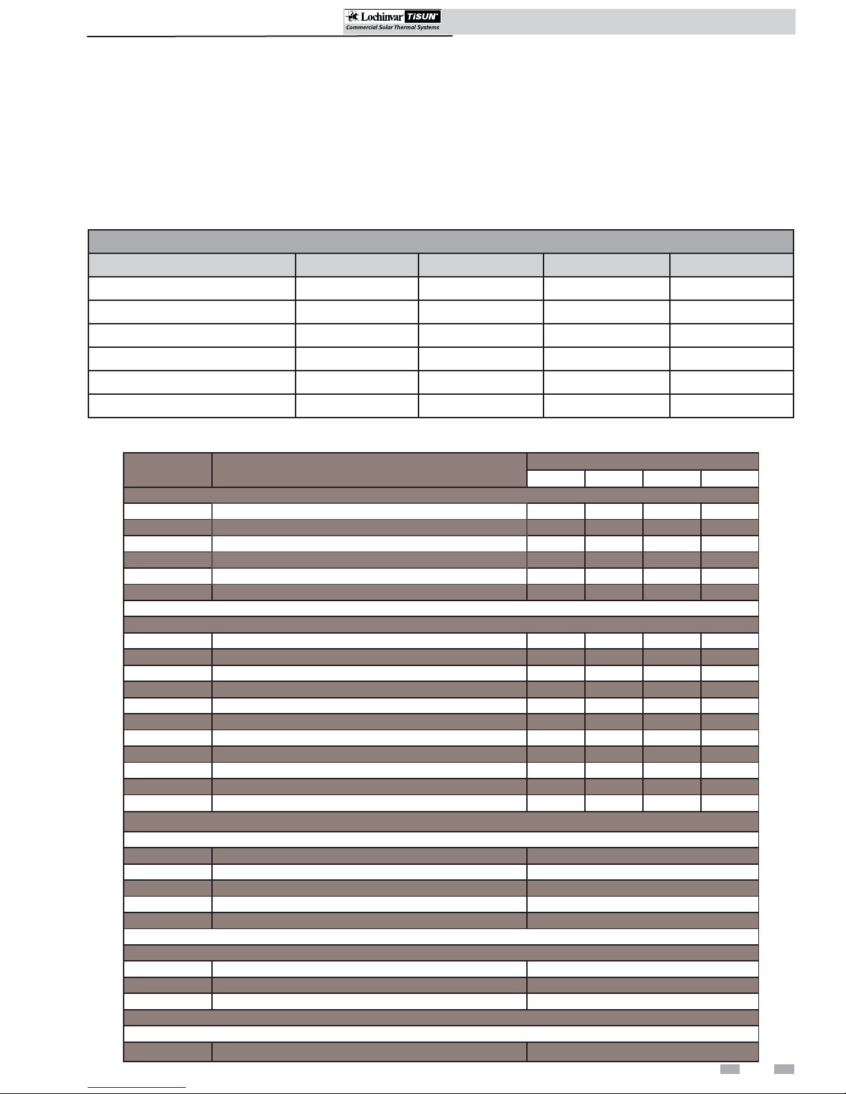
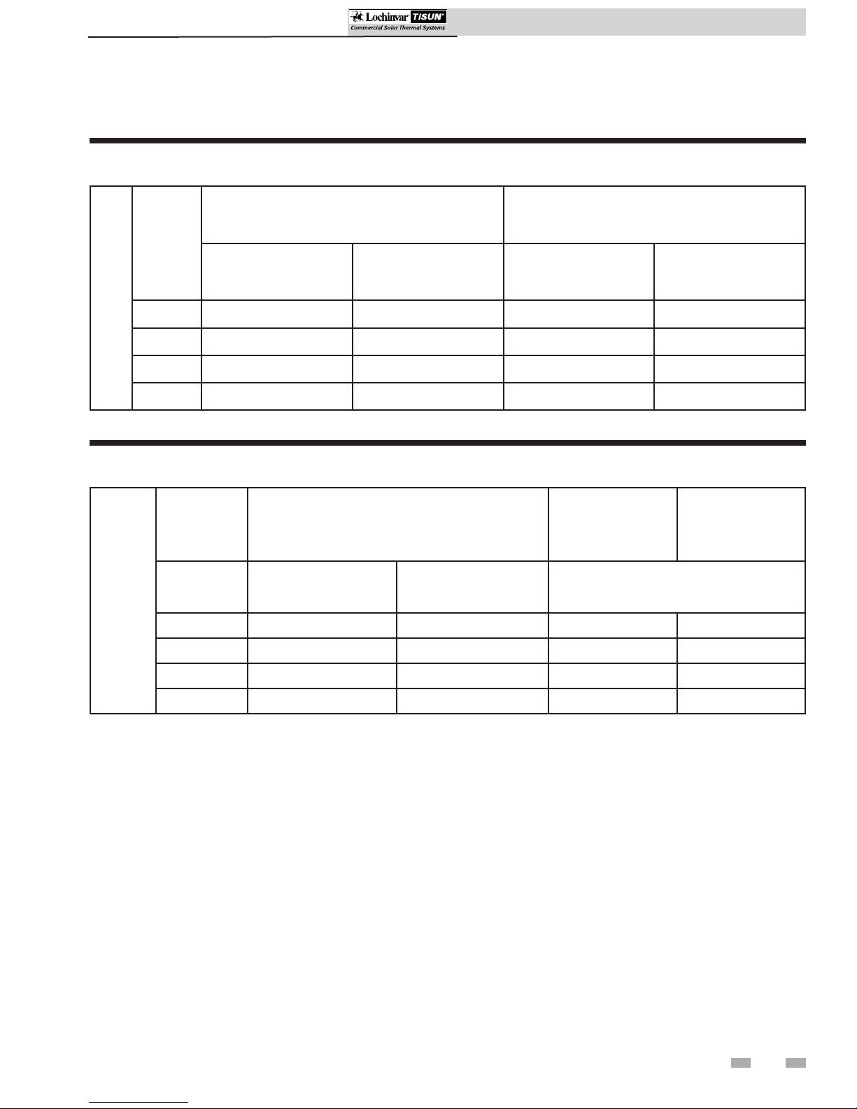
Technical data
SCH Collector
Type SCH065 SCH090 SCH110 SCH130
Quantity of Glass Panels 3 4 5 6
Gross area 65.66 ft
Aperture surface area 58.45 ft
Absorber surface area 59.85 ft
External Dimensions (L x W)
1
6'-7" x 9'-10" 6'-7" x 13'-2" 6'-7" x 16'-4" 6'-7" x 19'-7"
2
2
2
87.19 ft
77.93 ft
79.76 ft
Weight Ratings 309 lbs. 411 lbs. 513 lbs. 614 lbs.
SCH mounting hardware + hydraulic connection kits
Part-number Description
Parallel installation:
SCA20001 Horizontal aluminum bar 10 ft 2
SCA20002 Horizontal aluminum bar 13 ft 2
SCA20003 Horizontal aluminum bar 16 ft 2
SCA20004 Horizontal aluminum bar 20 ft 2
SSK20004 End bracing kit 2222
SSK20005 Z-hook kit 2333
2
2
2
108.72 ft
97.95 ft
99.67 ft
2
2
2
Needed quantities for:
SCH065 SCH090 SCH110 SCH130
130.24 ft
116.90 ft
119.59 ft
2
2
2
Inclined (20°,40°,60°) installation:
SCA20001 Horizontal aluminum bar 10 ft 2
SCA20002 Horizontal aluminum bar 13 ft 2
SCA20003 Horizontal aluminum bar 16 ft 2
SCA20004 Horizontal aluminum bar 20 ft 2
SCA20005 Aluminum U-channel 10 ft 3
SCA20006 Aluminum U-channel 13 ft 3
SCA20007 Aluminum U-channel 16 ft 3
SCA20008 Aluminum U-channel 20 ft 3
SSK20001 A-frame 20° inclined 2334
SSK20002 A-frame 40° inclined 2334
SSK20003 A-frame 60° inclined 2334
Hydraulic connection kits: (1 array is max. 2 SCH’s!)
HYK20001 Hydr. conn. kit 2x 6.5' + plug + sensor well 1x per collector or array
HYK20002 Hydr. conn. kit 1x 6.5'/1x 13' + plug + sensor well 1x per collector or array
HYK20003 Serial hydr. exp. kit for stacked installation 1x per array
HYK20004 Parallel hydr. exp. kit for side by side installation 1x per array
HYK20005 Serial hydr. exp. kit for side by side installation 1x per array
Mechanical connection kits: (optional for installation!)
MCK20001 Mechanical conn. kit for side by side installation 1x per array
MCK20002 Mechanical conn. kit for stacked installation 1x per array
MCK20003 Cover for piping (for side by side installations) 1x per array
Gable bracing kits: (required for non-south facing installation!)
GBK20003 Bracing kit w/ diagonal support 1x per collector
3
Page 4
1 Introduction
SCH Collectors Installation & Operation Manual
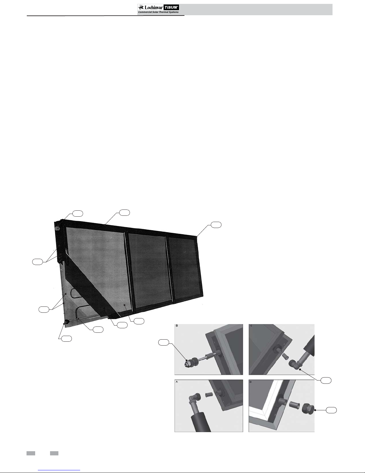
How it works...
1. Housing
Powder coated (RAL7016)aluminum frame structure with
PU rigid foam and an aluminum rear wall.
2. Cover
Prismatic solar safety glass, .15" thick, for maximum light
transmission.
3. Insulation
.76" heat resistant, special PU rigid foam and 1.57" mineral
wool with high pressure resistance, emission free, non flammable.
4. Absorber
Full surface absorber, laser welded with highly-selective PVD
coating (PVD = Physical Vapor Deposition), serpentine flow.
5. Collector seal
Aluminum profile system with double temperature and UV resistant silicone seals, emission free.
SCH Collector
7
1
6. Inlet connection
Copper pipes, .86" diameter.
7. Outlet connection
Copper pipes, .86" diameter.
8. Absorber coils
10 mm copper, serpentine arrangement.
9. Hydraulic connection kit
Connection set with stainless steel corrugated pipe. For connecting
the collector supply and return to the riser. The corrugated pipes
are available in kits with 2 x 6'-7" or 2 x 13'1" length including
sensor well and plug.
10. Sensor well
For measuring the collector outlet temperature directly in
the fluid. The sensor well can be installed on the outlet connection
as shown on the collector label. The sensor must be inserted up to
the end of the sensor well.
11. Plug
This plug is used on the end collector of each array to complete the
water flow path.
7
5
3
2
8
6
4
10
9
4
11
Page 5
1 Introduction (continued)
SCH Collectors Installation & Operation Manual
SCH Collectors Installation & Operation Manual
Before getting started on your installation be sure to carefully
read the preparation instructions in this section.
WARNING
NOTICE
CAUTION
Installer – Read all instructions, including
this manual before installing. Perform
steps in the order given.
Have your collector(s) serviced/inspected
by a qualified service technician, at least
annually.
Failure to comply with the above could
result in severe personal injury, death or
substantial property damage.
When calling or writing about the collector
– Please have the collector model and
serial number.
Any claims for damage or shortage in
shipment must be filed immediately
against the transportation company by the
consignee.
Factory warranty (shipped with the
collector) does not apply to collectors
improperly installed or improperly
operated.
• You must comply with local
regulations, laws and standards of the
local governing authority.
• The frame must be capable of
withstanding the local snow and wind
loads and permit the correct
anchoring of the collectors in
accordance with all applicable local
regulations.
• The load bearing capacity of the
roofing and the frame shall be specially
checked or analyzed by a structural
engineer.
• The number of mounting brackets
specified by the Lochinvar/TiSun
manuals and parts sheets is based on
an average collector load bearing per
square foot. The maximum
permissible collector loading per
square foot may be calculated from the
number of mounting brackets, taking
into consideration the permissible
loading on the mounting brackets. If a
higher collector wind and snow loading
(including snow sliding off the roof)
per square foot is required, additional
mounting brackets will have to be
used. Roof pitches in excess of 30° also
represent increased loading; additional
mounting brackets must also be used
for this variant.
CAUTION
CAUTION
CAUTION
Lochinvar/TiSun Solar Thermal Collectors
are not specifically designed for drain back
installations. Consult the factory if drain
back utilization is necessary.
• The mounting substructure must be
capable of withstanding the local
snow and wind loads and permit
correct anchoring of the collectors.
• To avoid damage to the collectors
and mounting frames from snow
sliding off the roof, additional snow
guards must be placed in sufficient
numbers around the collectors and
above the collectors.
• The collectors must be linked with a
lightning arrester system and/or the
building’s ground system by a licensed
electrician.
• Hydraulic connection of the collectors
must be performed according to
Lochinvar/TiSun specifications.
• The collector connections must not be
damaged, soiled or misaligned. Take care
during transport, installation, and
connection of the modules. Do not
remove the header protection caps at the
top and bottom connections of the
collector until just before installation.
• When connecting the modules to the
riser, the Hydraulic Connection Kit
(corrugated pipe) supplied must be
installed. Otherwise, the warranty is
invalidated.
• Always connect the collector outlet and
inlet flow to each other diagonally,
please follow the connection
example (see FIG. 1-1 on page 6).
• Do not twist the headers when screwing
the connections together. Hold threaded
connection in the desired position and
tighten clamping ring union nut to
torque.
• Roof penetrations for solar piping must
be adequately sealed against water ingress.
• Use only the original sensor well
supplied.
• Use only high temperature and glycol
pipe sealing materials.
All piping should be properly insulated to
avoid freezing and/or burn potential.
5
Page 6
1 Introduction
SCH Collectors Installation & Operation Manual
NOTICE
• Check the materials for any damage
sustained in transport and describe any
damage in writing on the packing slip
where necessary. This is important to
process any needed freight or delivery
damage claims.
• Carefully read through the relevant
installation instructions before
starting the installation and follow
each step.
• Use only the original mounting
components.
• Stainless steel screws may not be used
again once they have been removed
(because of the possibility of
breaking).
• Any conversion or modification of the
Lochinvar/TiSun product not
expressly approved in writing by the
manufacturer shall void the warranty.
• No liability can be accepted for damage
resulting from failure to observe the
installation instructions.
WARNING
WARNING
Figure 1-1 Connection Diagram
A properly sized expansion tank must be
used to avoid damage to the Solar Thermal
System.
If copper pipe is being used, all joints
MUST BE brazed, no soldering allowed.
WARNING
WARNING
WARNING
WARNING
WARNING
Dismantling and Disposal
• The units are dismantled in the reverse sequence of
installation.
• The roofing shall be properly sealed after the
mounting brackets have been removed.
• Materials shall be disposed of in an environmentally
conscious manner.
Only authorized solar companies familiar
with our products may handle them.
There is a risk of injury when handling
collectors and mounting accessories as
these have sharp edges.
The collector becomes very hot in the
sunlight. There is a risk of burn.
Comply with all safety regulations and
applicable OSHA requirements.
Check the load bearing capacity and
stability of the substructure onto which
the collector is to be installed and will
need to be accessed during the installation
process.
6
Page 7
SCH Collectors Installation & Operation Manual
2 Location
Array options
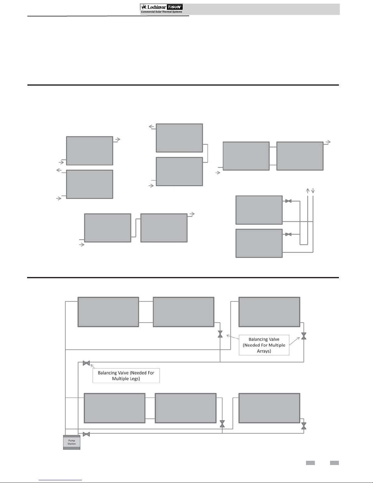
For series and parallel connection of multiple collectors, it is advisable to calculate the pressure drop over the entire system with
the aid of the enclosed documents and to install an appropriate pump if necessary. The maximum collector area per collector
array connected in series is 260 ft2. Be aware of pressure drop, reference the array options (FIG.’s 2-1 and 2-2).
Figure 2-1 Array Piping
SERIES STACKED
SINGLE COLLECTOR
Figure 2-2 Multiple Array Piping
PARALLEL SIDE BY SIDE
PARALLEL WITH BALANCING VALVES
(ON ROOF ONLY)
SERIES SIDE BY SIDE
7
Page 8
2 Location
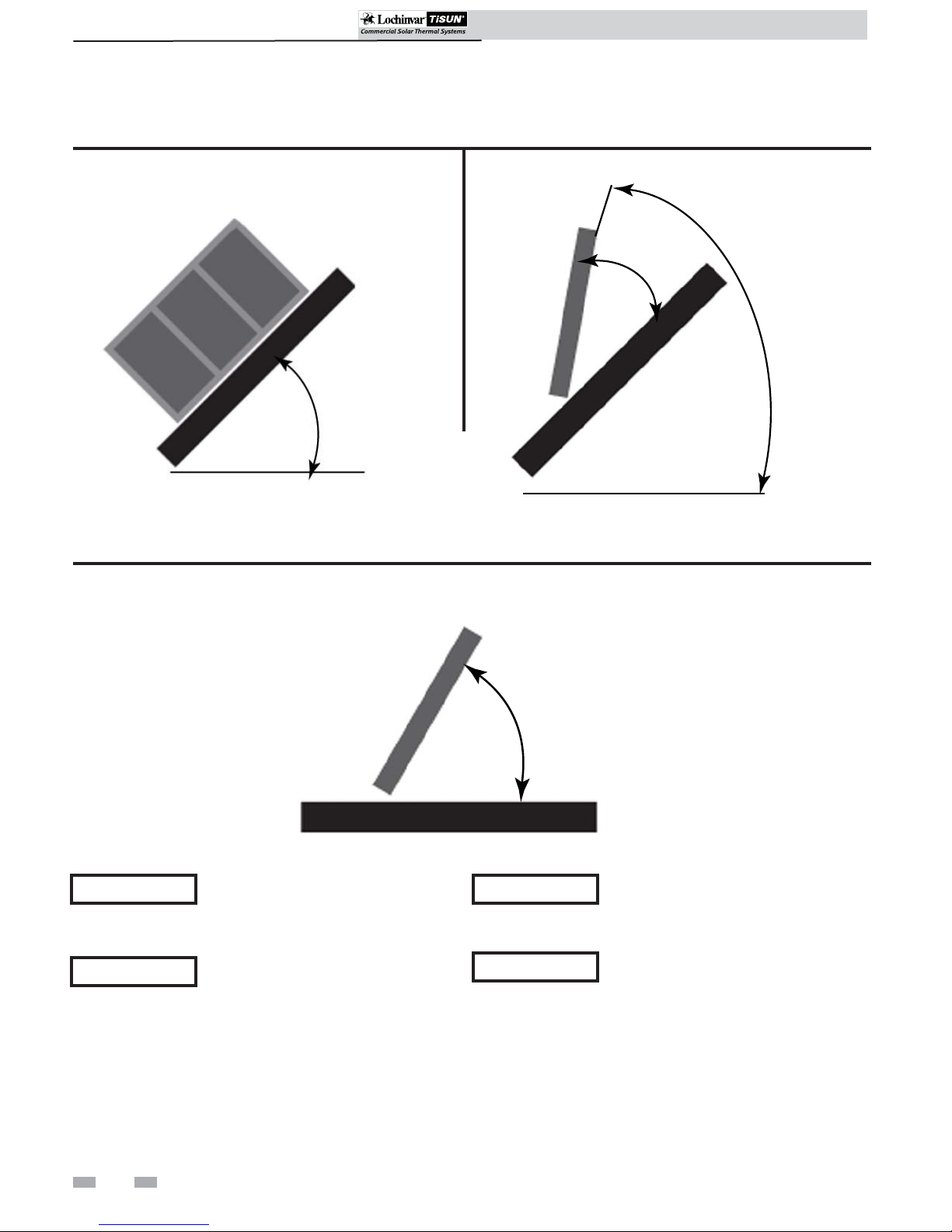
Installation positions
SCH Collectors Installation & Operation Manual
Figure 2-3 SCH Parallel Installations
min. 15° - max. 70°
Figure 2-5 SCH Freestanding Installations
Figure 2-4 SCH Inclined Installations
20°/40°/60°
min. 15° - max. 70°
NOTICE
NOTICE
For best performance, it is recommended
that the collectors face true south.
It is not recommended for the collector
field to deviate any further than 45°
from true south.
min. 15° - max. 70°
NOTICE
NOTICE
Collector incline should be at least 15° and
no more than 70° for best performance.
Avoid installation in shaded areas. Shaded
areas will reduce the performance of the
solar collectors.
8
Page 9
2 Location (continued)
Handling and storing
WARNING
CAUTION
NOTICE
• Installation of LOCHINVAR/TiSun
SCH collectors is only allowed for
professional staff.
• Local instructions, laws and standards
are to be kept.
• Collectors are to be located so
falling of snow and ice does not
endanger any person or property.
• Use personal protection equipment
(helmet, belt, security shoes) when on
the roof.
• Secure tools and materials against
falls.
• It is forbidden to stand under
hanging load.
• Danger area has to be closed.
• Put ladders up properly and check
stability.
• Check the under roof construction on
the building before installation.
SCH Collectors Installation & Operation Manual
WARNING
• Only loosen the crane connection
when the collectors are completely
fixed to the substructure.
• Pay special attention to roof-work
near an electric grid. If need be, the
constructor must take security
precautions such as isolation,
covering, etc.
• Inspect the roof surface in the area of
the installation for cracks, water
leakage, and roofing material quality
and uniformity. This is especially
important if the roof is more than 10
years old.
• Inspect the roof for sags and other
abnormalities. A sag or deep
depression in the roof may indicate a
structural weakness in the support
system that may require correction.
• Check that all rafters, trusses and
other materials are in good condition.
WARNING
• Avoid rotating movements of the
load through wind. Secure load
before lifting.
What to avoid
CAUTION
• Only move collectors on the given
fixing loops.
NOTICE
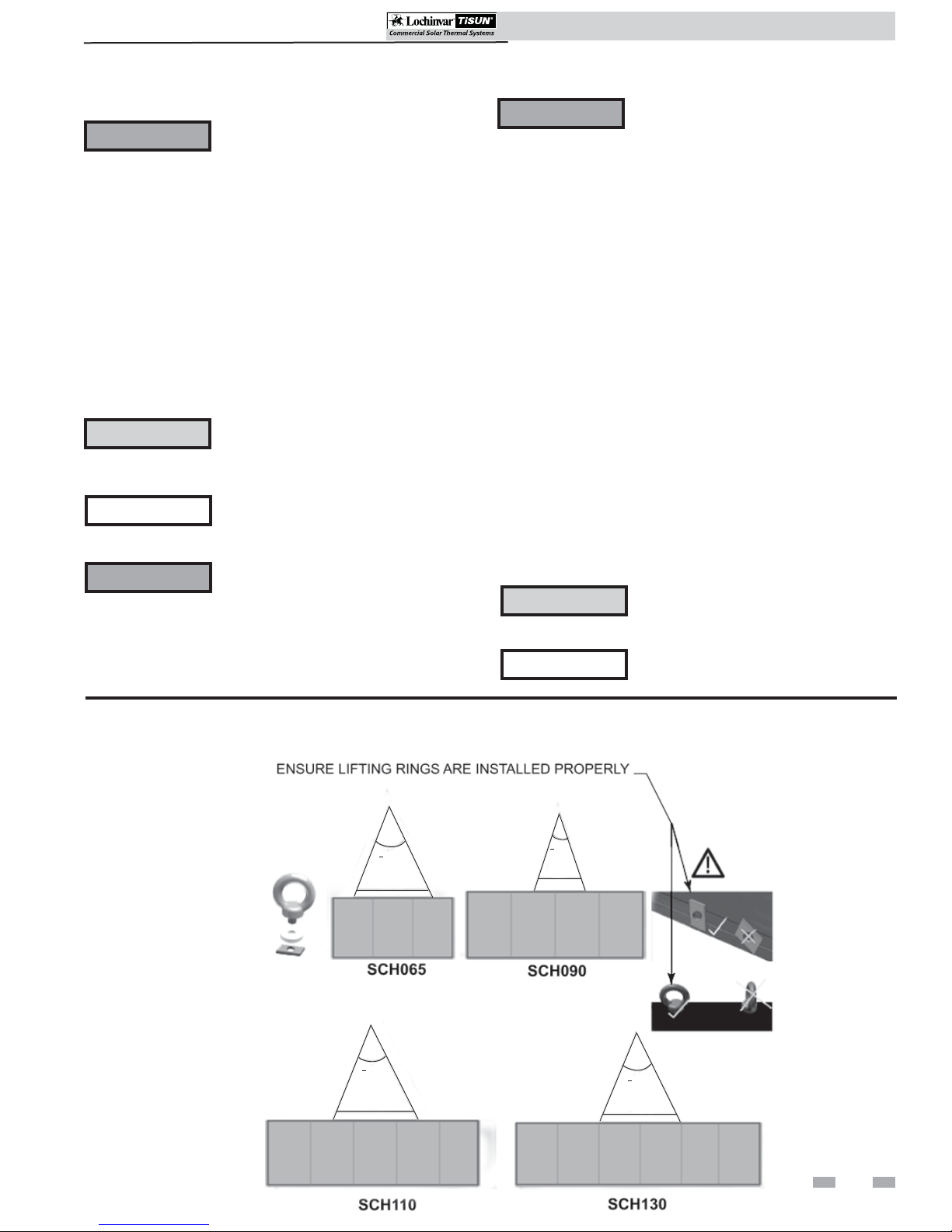
Figure 2-6 Crane Transportation Connection Points and Positioning
< 30°
6.5 ft.
• Collectors are to be located such that
eventual sliding of snow and ice does
not endanger any person.
• See FIG. 2-6 for crane transportation
connection points and positioning.
< 30°
6.5 ft.
< 30°
6.5 ft.
< 30°
8.5 ft.
9
Page 10
SCH Collectors Installation & Operation Manual
SCH Collectors Installation & Operation Manual
3 Roof Attachment Installation
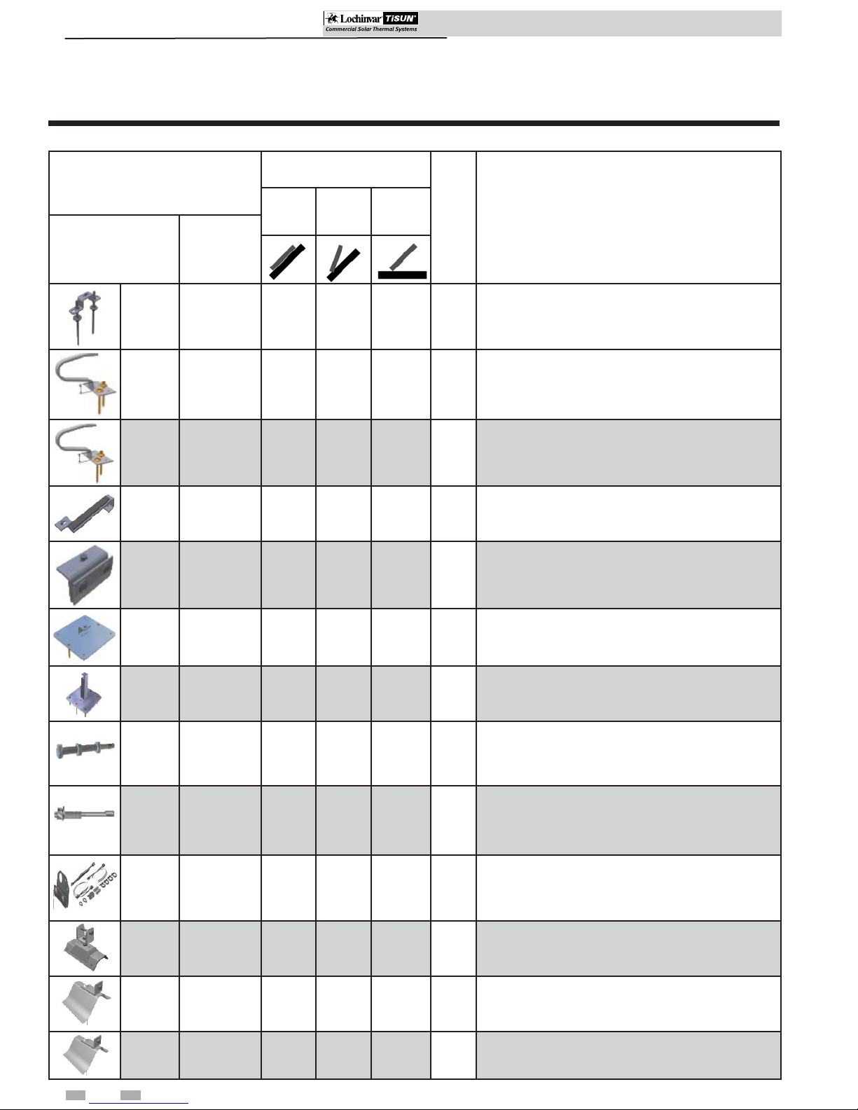
Roof attachment types
Table 3A Roof Fastenings - Parts
SOLAR ROOF MOUNTS
Part #
SRM20001
SRM20003
SRM20004
SRM20005
SRM20006 CLAMP, JOINT XX
Lochinvar
Name
BOLT,
DOUBLE
HANGER
ANCHOR,
RAFTER, STD
ROOF TILE
ANCHOR,
RAFTER, TALL
ROOF TILE
HOOK, FLAT
TILE
Installation Type
Parallel Inclined Free-
standing
XX X13
XX
XX
X
--
-
-
-
See
Page
15
15
16
18
Description
Stainless steel attachment for universal heavy duty
installations, on parallel and inclined roofs and
freestanding installations on sufficiently anchored
bases.
Stainless steel attachment for parallel and inclined
installations on various types of tiled roofs. Standard
installations for tile heights of up to 1.5". Package is
complete with fasteners and spacers.
Stainless steel attachment for parallel and inclined
installations on various types of tiled roofs. Standard
installations for tile heights of up to 2". Package is
complete with fasteners and spacers.
Stainless steel attachment for parallel installations on
plain tile, slate, and flat cement tiled roofs with pitches
in excess of 30 degrees.
Stainless steel attachment for parallel and inclined
installations on jointed tin, galvanized, or copper
roofs. Additional securing cables (Lochinvar Part #
SRM20012) are required for inclined installations.
SRM20007
SRM20008
SRM20009
SRM20010
SRM20012
SRM20013
SRM20014
SRM20015
10
PLATE,
FLANGE,
SHINGLE, STD.
PLATE,
FLANGE,
SHINGLE,
RAISED
BOLT,
ANCHOR,
CONCRETE W/
ADJ
BOLT,
ANCHOR,
CONCRETE
KIT, UNIV
CABLE
SECURING
ATTACHMENT,
ROOF CORR
METAL
ATTACHMENT,
WAVE ROOF SMXX
ATTACHMENT,
WAVE ROOF LGXX
XX X20
-
-
-
-
XX
XX22
XX26
XX26
X
Galvanized steel attachment for parallel, inclined and
freestanding installations on asphalt or elastomer
roofs.
Galvanized steel attachment for inclined and
freestanding installations on asphalt or elastomer
roofs. Also recommended for flat roofs.
Galvanized steel attachment for inclined or freestanding
installations with 2.75" height adjustment. For use in
applications with no more than a 5 degree inclination.
Galvanized steel attachment for inclined or
freestanding installations with no height adjustment.
For use in applications with no more than a 5 degree
inclination.
Stainless steel cable set for securing collectors on
inclined jointed roofs. Kit includes cable, turnbuckle,
-
-
-
-
19
hardware for attachment to frame, and joint clamp.
For inclined installations only.
Stainless steel attachment for parallel and inclined
23
installations on profiled and corrugated roofs.
Galvanized steel attachment for installations on
25
concrete corrugated roofs with 5 corrugations per
meter. For parallel and inclined installations.
Galvanized steel attachment for installations on
25
concrete corrugated roofs with 8 corrugations per
meter. For parallel and inclined installations.
10
Page 11
SCH Collectors Installation & Operation Manual
SCH Collectors Installation & Operation Manual
3 Roof Attachment Installation (continued)
Roof attachment quantities for SCH collectors snow loading
Table 3B Parallel Installations
SRM: 20001, 20003, 20004, 20006, 20007,
20013, 20014, 20015
area load up to
32 lb/sq-ft
SCH065 610610
SCH090 812812
SCH110 814814
Parallel installation
SCH130 10 18 10 18
Table 3C Inclined (20°, 40°, and 60°) Installations
SRM: 20001, 20003, 20004, 20007, 20008,
20009, 20010, 20013, 20014, 20015
area load up to 32 lb/
sq-ft
area load up to
64 lb/sq-ft
area load up to 64 lb/
sq-ft
SRM: 20005
area load up to
16 lb/sq-ft
SRM: 20006 + 20012
area load up to 64 lb/sq-ft
area load up to
32 lb/sq-ft
SCH065 610122
installation
SCH090 812143
Inclined (20, 40°, 60°)
SCH110 814183
SCH130 10 18 22 4
11
Page 12
SCH Collectors Installation & Operation Manual
SCH Collectors Installation & Operation Manual
3 Roof Attachment Installation
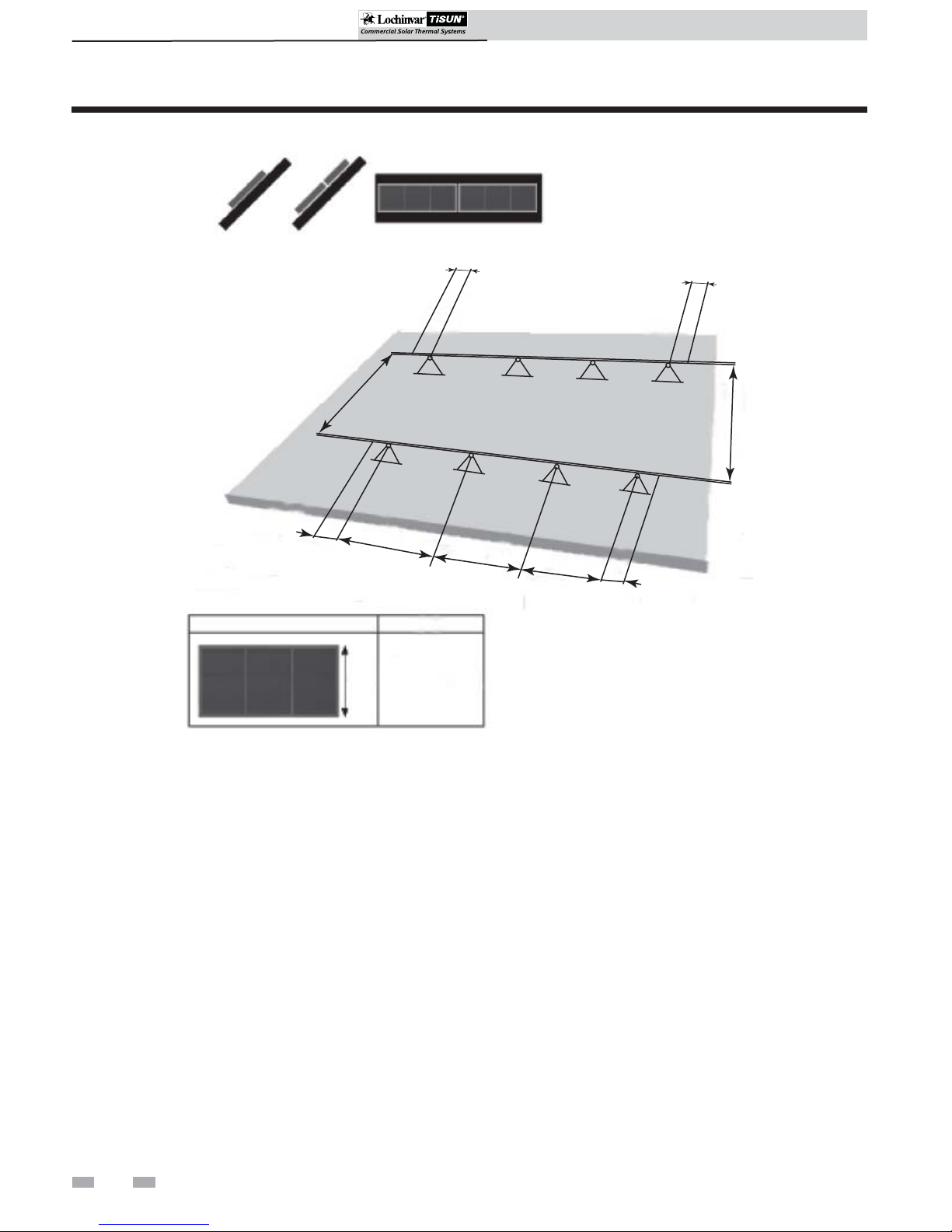
Figure 3-1 Spacing Distance
a = 2 - 10 in.
a
=
a
=
55 - 63 in.
=
X
=
a
a
x
Spacing Distance
Equally space the center roof attachments starting in the
middle, the two (2) end attachments will be spaced according
to the inner measurement (start in the middle and work
outwards). The remaining roof mounts should be equally
spaced in between the two (2) end roof attachments.
Note: For multiple collector installations reference the
Collector Mounting Section of this manual for spacing
between collectors.
12
Each collector will have its own independent substructure set.
Ensure there is ample room on the chosen roof area for the
number of collectors chosen.
Page 13
SCH Collectors Installation & Operation Manual
SCH Collectors Installation & Operation Manual
3 Roof Attachment Installation (continued)
Installation of roof attachment types
The solar thermal collectors are capable of being mounted to several different types of roofing with a wide variety of
mounting hardware available from Lochinvar.
Double hanger bolt for universal fastening
#SRM20001
Universal fixture for parallel and inclined installation on
various roof types and freestanding installation on sufficiently
anchored frames. Two hanger bolts are to be installed on the
roof as vertically as possible with a spacing of 4 3/4" to 6 3/4".
The two are connected by an intermediate plate.
CAUTION
• The hanger bolt must be screwed
into a support capable of bearing
the required static load (generally
rafters).
• Install the hanger bolt using a field
supplied anchoring adapter.
• The roofing must be capable of
withstanding the pressure needed
to compress the gasket.
• Beware of linear expansion in sheet
metal that prevents a linear
expansion and can cause lifting of
the sheet.
Unpacking and checking parts
When unpacking the system, check the model names of the
components of each system and check to be sure you have the
correct number of parts (see FIG. 3-2).
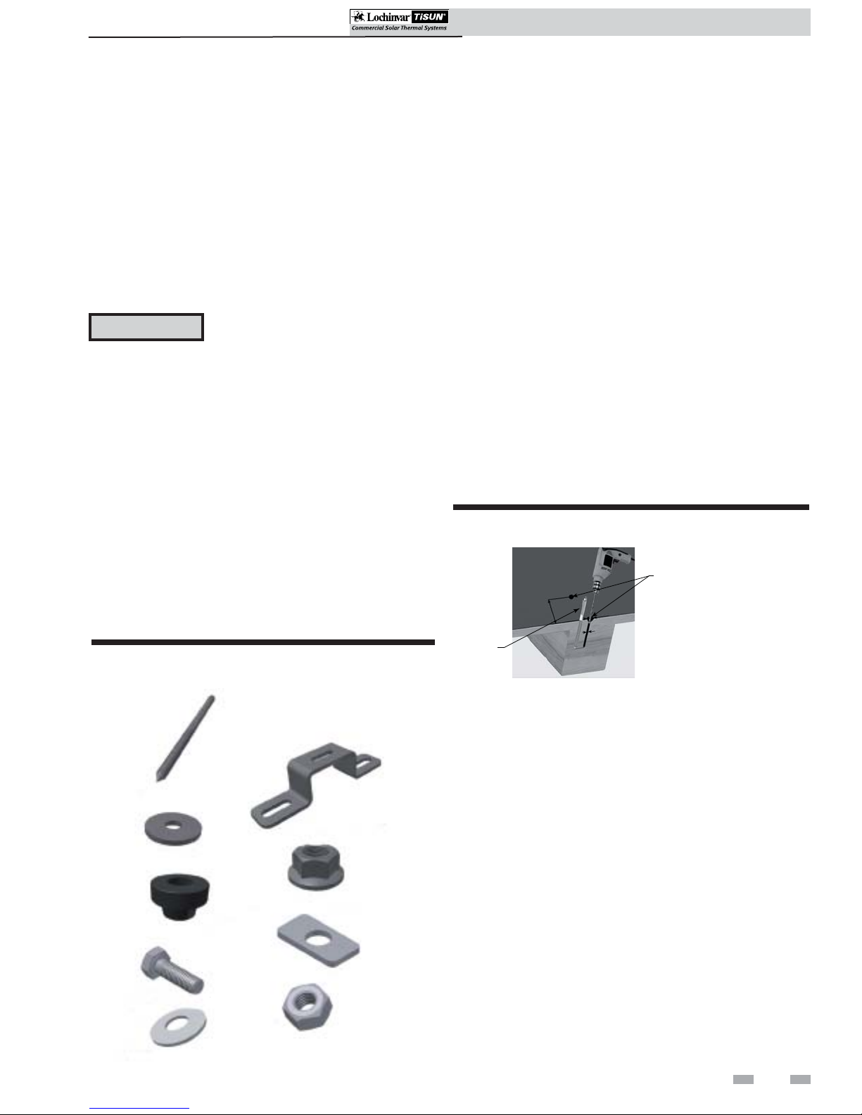
Figure 3-2 Kit #SRM20001 - Double Hanger Bolt Kit
Components
Install double hanger bolt
1. Determine roof type. Inspect the structural integrity of
the roof and the durability of the roof materials.
2. Determine the number of collectors needed for the
installation and the number of required roof attachments
from Table 3B or 3C on page 11.
3. Determine collector connection points (spacing).
Measure the spacing of the rafters or trusses to confirm
the dimensions and prepare for the system layout
(reference the Roof Attachment Spacing Section on
page 12).
4. Pre-drill two 9mm holes, a minimum of 4 inches deep
into the roof substructure (see FIG. 3-3), perpendicular
to the roof with a spacing of 4 3/4" to 6 3/4".
5. Install the hanger bolts into the pre-drilled holes
until the threads are level with the roof’s surface.
Figure 3-3 Pre-Drill 9mm Holes Into Substructure
PRE-DRILL TWO (2) 9MM HOLES
PERPENDICULAR TO THE ROOF
(APPROX. 4 IN. DEEP)
INSTALL
HANGER
BOLT(S)
HANGER BOLT (M12) (2X)
DOUBLE HANGER BOLT PLATE (1X)
WASHER (M12) (2X)
HEX NUT W/FLANGE (M12) (6X)
HANGER BOLT SEAL (2X)
SQUARE DISK (1X)
HEX BOLT (M8) (1X)
HEX NUT (M8) (1X)
WASHER (M8) (1X)
6. Slide the hanger bolt seals over the machine threads until
the seal is touching the roof’s surface (FIG. 3-4A).
7. Slide the washer (M12) on top of the hanger bolt seal
(FIG. 3-4A).
8. Thread the hex nut with flange (flange side down) onto
the washer, compressing the washer and hanger bolt seal
to the roof (FIG. 3-4B).
9. Install the second hex nut with flange (flange side up)
until the hex nut reaches the desired substructure height
(FIG. 3-4B).
10. Slide the hanger bolt plate onto the flange of the hex nut
installed in Step 9 (FIG.’s 3-4A and 3-4B).
11. Install the remaining hex nut with flange (flange side
down) to the top of the double hanger bolt plate.
Tighten and secure both hex nuts (top and bottom) to
the double hanger bolt plate.
12. Make certain all double hanger bolt plates are facing the
same direction.
13
Page 14
SCH Collectors Installation & Operation Manual
SCH Collectors Installation & Operation Manual
3 Roof Attachment Installation
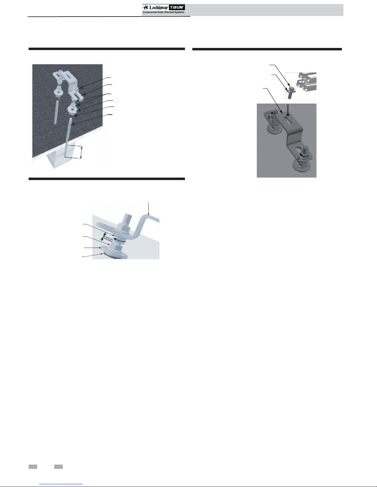
Figure 3-4A Install Double Hanger Bolt Components
HEX NUT W/FLANGE
HANGER BOLT PLATE
HEX NUT W/FLANGE
WASHER (M12)
HANGER BOLT SEAL
HANGER BOLT
min.
4”
Figure 3-4B Compress Washer and Hanger Bolt Seal
DOUBLE HANGER BOLT PLATE
HEX NUT
FLANGE UP
Figure 3-5 Install Hex Bolt(s)
HEX BOLT
SQUARE DISK
DOUBLE HANGER
BOLT PLATE
NUT
WASHER
SEAL
13. Slide the square disk onto the hex bolt (see FIG. 3-5).
14. Install the hex bolt with square disk attached into the
opening of the double hanger bolt plate as shown in
FIG. 3-5.
Note: Do not tighten hex bolts until ready to install on the
collector substructure.
15. Thread the hex nut (M8) and washer (M8) onto the
bottom of the hex bolt installed in Step 14 (FIG. 3-5).
16. Repeat Steps 4 - 15 until installation is complete.
Install hex bolt onto collector substructure (reference Section
4 - Collector Installation)
14
Page 15

SCH Collectors Installation & Operation Manual
SCH Collectors Installation & Operation Manual
3 Roof Attachment Installation (continued)
Rafter anchor for roof tiles
#SRM20003 & #SRM20004
The rafter anchor is used for parallel and inclined mounting
on tiled roofs with a roof pitch of at least 15° and an area
loading greater than 6 lb/ft2. Can be used for various types
of roofing tiles.
CAUTION
• The anchors must be screwed into
a support capable of bearing the
required static load (generally
rafters or concrete).
• Complies with the requirements of
DIN1055.
• Roof batten height at least 1".
• The gap between rafter anchor
and top edge of the tile must be at
least 3-5mm. Under no
circumstances may the rafter
anchor be in contact with the tile
(if the overall height of roof batten
and tile do not match, the lower
height must be packed out).
Unpacking and checking parts
Install rafter anchor
1. Determine roof type. Inspect the structural integrity of
the roof and the durability of the roof materials.
2. Determine the number of collectors needed for the
installation and the number of required roof attachments
from Table 3B or 3C on page 11.
3. Determine collector connection points (spacing).
Measure the spacing of the rafters or trusses to confirm
the dimensions and prepare for the system layout
(reference the Roof Attachment Spacing Section on
page 12).
4. Number two (2) tiles, one above the other. The upper
tile will be removed to install the rafter anchor.
5. Mark the edge of the upper tile on the lower tile to
ensure proper alignment upon assembly.
6. Using the rafter anchor as a template, pre-drill two (2)
6 mm holes, approximately 4 inches deep into the roof
substructure (see FIG. 3-7), perpendicular to the roof.
When unpacking the system, check the model names of the
components of each system and check to be sure you have the
correct number of parts (see FIG. 3-6).
Figure 3-6 Kit #SRM20003 & #SRM20004 - Rafter
Anchor Kit Components
RAFTER ANCHOR (1X)
WOOD SCREW (2X)
SPACER PLATE (3X)
SQUARE DISK (1X)
Figure 3-7 Pre-Drill 6mm Holes Into Roof Substructure
USE RAFTER ANCHOR
AS A TEMPLATE
PRE-DRILL TWO (2)
6MM HOLES
APPROX. 4” DEEP
PERPENDICULAR TO
THE ROOF
7. To achieve the recommended 3 - 5 mm clearance above the
tile, place the spacer plate(s) (provided in the kit) between
the rafter anchor and the roof substucture if necessary
(FIG. 3-8).
8. Place the rafter anchor on the spacer plate (if used).
9. Place the heavy duty washers over the holes pre-drilled in
Step 6.
10. Install the wood screws through the washers and rafter
anchor into the roof substructure.
WASHER (M8) (1X)
HEAVY DUTY WASHER (2X)
HEX NUT (M8) (1X)
HEX BOLT (M8) (1X)
Note: It may be necessary to grind the upper tile to assure a
better fit (FIG. 3-9).
15
Page 16

SCH Collectors Installation & Operation Manual
SCH Collectors Installation & Operation Manual
3 Roof Attachment Installation
Figure 3-8 Install Rafter Anchor
COLLECTOR SUBSTRUCTURE
HEX BOLT
RAFTER ANCHOR
Figure 3-9 Grind Tile (if necessary)
INSTALL WASHER
AND WOOD SCREW
SPACER PLATE
(IF NECESSARY)
IF NECESSARY, GRIND
THE TILE FOR A BETTER
FIT
Flat tile hook
#SRM20005
The flat tile hook is only used for parallel installation on
plain tiled roofs (generally steep roofs with a pitch of over
30°), the hooked ends are hung over the roof battens and
screwed in place, an inclined collector installation is not
possible here.
Unpacking and checking parts
When unpacking the system, check the model names of
the components of each system and check to be sure you
have the correct number of parts (see FIG. 3-10).
Figure 3-10 Kit #SRM20005 - Flat Tile Hook Kit
Components
FLAT TILE HOOK (1X)
11. Slide the square disk onto the hex bolt (see FIG. 3-8).
12. Install the hex bolt with square disk attached into the opening
of the rafter anchor as shown in FIG. 3-8.
Note: Do not tighten hex bolt until ready to install on the collector
substructure.
13. Thread the hex nut (M8) and washer (M8) onto the bottom of
the hex bolt installed in Step 12.
14. Repeat Steps 4 - 13 until installation is complete.
15. Replace tiles removed in Step 4.
Install hex bolt onto collector substructure (reference Section 4 Collector Installation)
HEX NUT (M8) (1X)
HEX BOLT (M8) (1X)
WOOD SCREW (1X)
METAL SHEET (1X)
SQUARE DISK (1X)
WASHER (M8) (1X)
NAIL (3X)
16
Page 17

SCH Collectors Installation & Operation Manual
SCH Collectors Installation & Operation Manual
3 Roof Attachment Installation (continued)
Install flat tile hook
1. Determine roof type. Inspect the structural integrity of
the roof and the durability of the roof materials.
2. Determine the number of collectors needed for the
installation and the number of required roof attachments
from Table 3B or 3C on page 11.
3. Determine collector connection points (spacing).
Measure the spacing of the rafters or trusses to confirm
the dimensions and prepare for the system layout
(reference the Roof Attachment Spacing Section on
page 12).
4. Number two (2) tiles, one above the other. The top tile
will be removed to install the flat tile hook.
5. Remove the top tile from the roof (set aside for
reassembly).
6. Place the tiled roof hook over the roof batten of
the bottom tile (FIG. 3-11).
7. Place the metal sheet provided in the kit under the flat
tile hook (FIG. 3-11). Using the nails provided in the kit,
secure the metal sheet to the roof substructure (FIG.
3-11).
Figure 3-12 Grind Tile(s) (if necessary) / Install Hex Bolt
COLLECTOR
SUBSTRUCTURE
HEX BOLT
SQUARE DISK
FLAT TILE
HOOK
IF NECESSARY, GRIND
THE TILE(S) FOR A BETTER
FIT
10. Slide the square disk onto the hex bolt (see FIG. 3-12).
11. Install the hex bolt with square disk attached into the
opening of the flat tile hook as shown in FIG. 3-12.
Note: Do not tighten hex bolt until ready to install on the
collector substructure.
8. Secure the tiled roof hook to the roof substructure using
the screws provided in the kit (FIG. 3-11).
9. Replace the tile removed in Step 5.
Note: It may be necessary to grind the top tile to assure a
better fit (FIG. 3-12).
Figure 3-11 Install Flat Tile Hook and Metal Sheet
HOOK FLAT TILE HOOK
ONTO ROOF BATTEN
WOOD
SCREW
NAIL
NAIL
USE THE NAILS AND
WOOD SCREW
TO SECURE
THE METAL
SHEET AND
FLAT TILE HOOK
TO ROOF
SUBSTRUCTURE
12. Thread the hex nut (M8) and washer (M8) onto the bottom
of the hex bolt installed in Step 11.
13. Repeat Steps 4 - 12 until installation is complete.
Install hex bolt onto collector substructure (reference Section 4 Collector Installation)
PLACE METAL SHEET
UNDER FLAT TILE HOOK
17
Page 18

SCH Collectors Installation & Operation Manual
SCH Collectors Installation & Operation Manual
3 Roof Attachment Installation
Joint clamp
#SRM20006
The joint clamp is only used for parallel and inclined
mounting on folded-seam tin roofs with galvanized or coated
sheet steel, or copper, reference the Universal Cable Securing
Kit on page 19.
CAUTION
• Not recommended for
titanium-zinc sheet due to
danger of cracks at low
temperature.
• Do not reuse any stainless steel
screws as there is a risk of
breakage.
Unpacking and checking parts
When unpacking the system, check the model names of the
components of each system and check to be sure you have the
correct number of parts (see FIG. 3-13).
Figure 3-13 Kit #SRM20006 - Joint Clamp Kit Components
Install joint clamp
1. Determine roof type. Inspect the structural integrity of
the roof and the durability of the roof materials.
2. Determine the number of collectors needed for the
installation and the number of required roof attachments
from Table 3B and 3C on page 11.
3. Determine collector connection points (spacing).
Measure the spacing of the rafters or trusses to confirm
the dimensions and prepare for the system layout
(reference the Roof Attachment Spacing Section on
page 12).
4. Assemble joint clamp as shown in FIG. 3-14 (be sure to
loosely assemble the screws on the joint clamp
assembly).
5. Place the joint clamp assembly at the appropriate
location on the joint of the tin roof.
6. Tighten the screws on the joint clamp to 26 ft./lbs.
Figure 3-14 Assemble / Install Joint Clamp & Hex Bolt
JOINT CLAMP 2 (1X)
HEX NUT (M8) (1X)
HEX BOLT (M8) (1X)
MUSHROOM HEAD BOLT (M10) (2X)
JOINT CLAMP 1 (1X)
SQUARE DISK (1X)
WASHER (M8) (1X)
HEX NUT (M10) (2X)
HEX BOLT
SQUARE DISK
ASSEMBLE JOINT CLAMP
INSTALL ON THE TIN
ROOF JOINT
JOINT
COLLECTOR
SUBSTRUCTURE
7. Slide the square disk onto the hex bolt (see FIG. 3-14).
8. Install the hex bolt with square disk attached into the
opening of the joint clamp as shown in FIG. 3-14.
Note: Do not tighten hex bolt until ready to install on the
collector substructure.
18
9. Thread the hex nut (M8) and washer (M8) onto the bottom
of the hex bolt installed in Step 8.
10. Repeat Steps 4 - 9 until installation is complete.
Install hex bolt onto collector substructure (reference Section 4 Collector Installation)
Page 19

SCH Collectors Installation & Operation Manual
SCH Collectors Installation & Operation Manual
3 Roof Attachment Installation (continued)
Universal cable securing kit
#SRM20012
For securing inclined collectors on tin joint roofs comprising
a guy cable, turnbuckle and hardware for collector frames
and joint clamp for guy cable tensioning. Material: stainlesssteel.
Joint clamp for cable set is required for mounting the guy
cable set on joint tin roofs with galvanized or coated sheet
steel or sheet copper (one in each guy cable set). The guy
cable set is fastened to the joint clamp. Note: The joint
clamp can also be used with a 1" pipe provided on site as
an additional snow guard above the collector (does not
replace the snow guard system provided on site which is a
requirement).
CAUTION
• Not recommended for titanium zinc sheet due to danger of
cracking at low temperatures.
• Do not reuse any stainless steel
screws as there is a risk of
breakage.
Unpacking and checking parts
Install cable securing kit
1. Install the anchor bracket on the A-frame using the hex
bolt, square disk, washer, and hex nut.
2. Assemble the joint clamp as shown in FIG. 3-17 (be sure to
loosely assemble the screws on the joint clamp
assembly).
3. Place the joint clamp assembly at the appropriate
location on the joint of the tin roof.
Figure 3-16 Attach Cable Fastening Bracket to A-Frame
ATTACH CABLE FASTENING BRACKET
TO THE COLLECTOR
CABLE FASTENING BRACKET
INSTALLED ON COLLECTOR
When unpacking the system, check the model names of the
components of each system and check to be sure you have the
correct number of parts (see FIG. 3-15).
Figure 3-15 Kit #SRM20012 - Universal Cable Securing Kit
Components
JOINT CLAMP
PART 2 (1X)
HEX BOLT W/FLANGE (2X)
HEX BOLT (M10) (1X)
HEX NUT (M8) (2X)
WASHER (1X)
JOINT CLAMP
PART 1 (1X)
NUT (2X)
SQUARE DISK (2X)
HEX BOLT
(M8) (2X)
WASHER
(M10) (1X)
Figure 3-17 Assemble Joint Clamp
ASSEMBLE JOINT CLAMP LOOSELY
AND PLACE ON JOINT
SQUARE NUT (1X)
CABLE KIT (1X)
19
Page 20

SCH Collectors Installation & Operation Manual
SCH Collectors Installation & Operation Manual
3 Roof Attachment Installation
4. Choose a cable orientation to ensure proper degree of
angle (see FIG. 3-18).
5. Install the steel cable on the A-frame bracket using the
pin and pin clip provided in the kit (see FIG. 3-19).
Figure 3-18 Cable Orientations
Figure 3-19 Install Steel Cable on A-frame
INSERT PIN
USE PIN CLIP TO SECURE
THE CABLE
Figure 3-20 Cable Angle
Flange plate shingle (standard)
#SRM20007
The standard flange shingle plate is used for parallel and inclined
installations on asphalt and elastomer roofs.
CAUTION
• The plates must be screwed into a
support capable bearing the
required load (generally rafters or
concrete).
• Once installed, the plates must be
sealed to the roof sheet material
(see FIG. 3-24), and only then can the
collector be fitted.
INSTALL CABLE
(TURNBUCKLE)
CABLE (TURNBUCKLE)
INSTALLED
6. Attach the steel cable to the joint clamp (fashioned after
the cable orientations in FIG. 3-18.
NOTICE
Extend turnbuckle to its fullest extent.
7. Before tightening the joint clamp, set the angle of the
cable to greater than or equal to 30°, but less than or
equal to 45° (see FIG. 3-20).
8. Tighten the joint clamp.
9. Use the turnbuckle to tighten the cable.
Unpacking and checking parts
When unpacking the system, check the model names of the
components of each system and check to be sure you have the
correct number of parts (see FIG. 3-21).
Figure 3-21 Kit #SRM20007 - Flange Shingle Plate
(Standard) Kit Components
PLATE FLANGE (STD) (1X)
SCREW (M10) (4X)
SCREW (M6) (4X)
SQUARE DISK (1X)
HEX NUT (M8) (1X)
20
WASHER (M8) (1X)
HEX BOLT (M8) (1X)
Page 21

SCH Collectors Installation & Operation Manual
SCH Collectors Installation & Operation Manual
3 Roof Attachment Installation (continued)
Install flange plate shingle (standard)
1. Determine roof type. Inspect the structural integrity of
the roof and the durability of the roof materials.
2. Determine the number of collectors needed for the
installation and the number of required roof attachments
from Table 3B or 3C on page 11.
3. Determine collector connection points (spacing).
Measure the spacing of the rafters or trusses to confirm
the dimensions and prepare for the system layout
(reference the Roof Attachment Spacing Section on
page 12).
4. Caulk (field supplied) around the perimeter of the flange
plate (FIG. 3-22).
5. Using the flange plate as a template, place the flange plate
on the roof and drill four (4) 6 mm holes as shown in
FIG. 3-23. Install the larger screws provided in the kit
into the 6mm holes securing the flange plate to the roof
(caulk around screws before tightening).
6. Install the four (4) remaining smaller screws in the
perimeter of the flange plate as shown in FIG. 3-23 (caulk
around screws before tightening).
Figure 3-23 Drill Holes and Attach Flange Plate
COLLECTOR
SUBSTRUCTURE
HEX BOLT
SQUARE DISK
USE THE SMALLER SCREWS
IN THE PERIMETER OF THE
FLANGE PLATE
PRE-DRILL FOUR (4) 6MM
HOLES - USE THE LARGER
SCREWS TO SECURE THE
FLANGE PLATE
Figure 3-24 Cover Flange Plate with Roofing Material
COVER FLANGE PLATE WITH
ROOFING MATERIAL, SEALING
IT TO THE ROOF
2”
7. Cover flange plate with roofing material, sealing it to the
roof (FIG. 3-24).
Figure 3-22 Caulk Around Perimeter of Flange Plate
CAULK AROUND
~ Ø 5 mm
THE PERIMETER
OF THE FLANGE PLATE
4.7”
4.7 mm
6”
> 4.7”
8. Slide the square disk onto the hex bolt (see FIG. 3-23).
9. Install the hex bolt with square disk attached into the
opening of the flange plate as shown in FIG. 3-23.
Note: Do not tighten hex bolt until ready to install on the
collector substructure.
10. Thread the hex nut (M8) and washer (M8) onto the bottom
of the hex bolt installed in Step 9.
11. Repeat Steps 4 - 10 until installation is complete.
Install hex bolt onto collector substructure (reference Section 4 Collector Installation)
21
Page 22

SCH Collectors Installation & Operation Manual
SCH Collectors Installation & Operation Manual
3 Roof Attachment Installation
Flange plate shingle (raised)
#SRM20008
The raised flange shingle plate is used for inclined installations
on asphalt and elastomer roofs; also suitable for flat roofs.
CAUTION
• The plates must be screwed into a
member capable of bearing the
required static load (generally
rafters or concrete).
• Once installed, the panels
must be sealed to the roof sheet
material (FIG. 3-28), and
only then can the collector be
fitted.
Unpacking and checking parts
When unpacking the system, check the model names of the
components of each system and check to be sure you have the
correct number of parts (see FIG. 3-25).
Figure 3-25 Kit #SRM20008 - Flange Plate (Raised) Kit
Components
Install flange plate shingle (raised)
1. Determine roof type. Inspect the structural integrity of
the roof and the durability of the roof materials.
2. Determine the number of collectors needed for the
installation and the number of required attachments
from Table 3B or 3C on page 11.
3. Determine collector connection points (spacing).
Measure the spacing of the rafters or trusses to confirm
the dimensions and prepare for the system layout
(reference the Roof Attachment Spacing Section on
page 12).
4. Caulk (field supplied) around the perimeter of the flange
plate (FIG. 3-26).
5. Using the flange plate as a template, place the flange plate
on the roof and drill four (4) 6 mm holes as shown in
FIG. 3-27. Install the larger screws provided in the kit
into the 6mm holes securing the flange plate to the roof
(caulk around screws before tightening).
6. Install the four (4) remaining smaller screws in the
perimeter of the flange plate as shown in FIG. 3-27 (caulk
around screws before tightening).
FLANGE PLATE RAISED (1X)
SCREW (M6) (4X)
HEX NUT (M8) (1X)
SCREW (M10) (4X)
SQUARE DISK (1X)
HEX BOLT (M8) (1X)
7. Cover the flange plate with roofing material, sealing it to
the roof (FIG. 3-28).
Figure 3-26 Caulk Around Perimeter of Flange Plate
CAULK AROUND
~ Ø 5 mm
THE PERIMETER
OF THE FLANGE PLATE
WASHER (M8) (1X)
22
Page 23

SCH Collectors Installation & Operation Manual
SCH Collectors Installation & Operation Manual
3 Roof Attachment Installation (continued)
Figure 3-27 Drill Holes and Attach Flange Plate
COLLECTOR
SUBSTRUCTURE
HEX BOLT
SQUARE DISK
USE THE SMALLER SCREWS
IN THE PERIMETER OF THE
FLANGE PLATE
PRE-DRILL FOUR (4) 6 MM
HOLES - USE THE LARGER
SCREWS TO SECURE THE
FLANGE PLATE
Figure 3-28 Cover Flange Plate with Roofing Material
COVER FLANGE PLATE WITH
ROOFING MATERIAL, SEALING
IT TO THE ROOF
2”
Corrugated metal roof attachment
#SRM20013
The corrugated metal roof attachment is used for parallel
and inclined mounting on profiled or corrugated sheet metal
roofs. The console is mounted above the mounting screws
of the profiled or corrugated sheet metal. The two sealing
screws are first screwed onto the underlying mounting
screw of the sheet. The sealing is done before the console is
mounted using the sealing pads supplied. The sections are
fixed to the section connectors on the console.
CAUTION
• The console must be ordered to
fit the relevant profiled or
corrugated sheet metal.
• The mounting screws supplied
with the console must be
appropriate in type and length for
the particular roof construction.
Unpacking and checking parts
When unpacking the system, check the model names of the
components of each system and check to be sure you have the
correct number of parts (see FIG. 3-29).
4.7”
4.7 mm
6”
> 4.7”
8. Slide the square disk onto the hex bolt (see FIG. 3-27).
9. Install the hex bolt with square disk attached into the
opening of the flange plate as shown in FIG. 3-27.
Note: Do not tighten hex bolt until ready to install on the
collector substructure.
10. Thread the hex nut (M8) and washer (M8) onto the bottom
of the hex bolt installed in Step 9.
11. Repeat Steps 4 - 10 until installation is complete.
Figure 3-29 Kit #SRM20013 - Corrugated Metal Roof
Attachment Kit Components
HEX NUT (M10) (1X)
STUD (M10) (1X)
PROFILE CONNECTOR (1X)
HEX BOLT (M8) (1X)
WASHER (M10) (2X)
HEX NUT (M10) (2X)
WASHER (M8) (1X)
Install hex bolt onto collector substructure (reference Section 4 Collector Installation)
23
Page 24

A
SCH Collectors Installation & Operation Manual
SCH Collectors Installation & Operation Manual
3 Roof Attachment Installation
Install metal roof attachment
1. Determine roof type. Inspect the structural integrity of
the roof and the durability of the roof materials.
2. Determine the number of collectors needed for the
installation and the number of required roof attachments
from Table 3B or 3C on page 11.
3. Determine collector connection points (spacing).
Measure the spacing of the rafters or trusses to confirm
the dimensions and prepare for the system layout
(reference the Roof Attachment Spacing Section on
page 12).
4. Attach the rubber seals provided in the kit to each end of
the metal roof attachment as shown in FIG. 3-30.
5. Place the metal roof attachment on top of an existing
fixing point of the metal roof (FIG. 3-31).
6. Using the metal roof attachment as a template pre-drill
two (2) 6.5 mm holes into the top of the metal roof
attachment (see FIG. 3-31).
7. Install hex bolts into pre-drilled holes as shown in
FIG. 3-32.
8. Install the four (4) self tapping screws provided in kit
into each side of the metal roof attachment (FIG. 3-32).
Figure 3-32 Install Hex Bolts and Stud
INSTALL STUD
(ALL THREAD)
INSTALL
HEX BOLTS & STUD
INSTALL SELF TAPPING SCREWS
10. Attach the profile connector to the stud using the
washers and hex nuts provided in the kit (FIG. 3-33).
11. Drill a 6.5 mm hole into the horizontal bar.
12. Place the horizontal bar into the profile connector
installed in Step 10.
13. Using the remaining bolts and washers secure the horizontal
bar into the profile connector.
9. Insert the stud (all thread) into the center of the roof
attachment.
Figure 3-30 Install Rubber Seals
INSTALL SEALING PADS
METAL ROOF
TTACHMENT
Figure 3-31 Pre-drill 6.5 mm Holes
PRE-DRILL 6.5 MM HOLES
Figure 3-33 Install Profile Connector
ATTACH PROFILE CONNECTOR
METAL ROOF ATTACHMENT
24
FIXING POINT
Page 25

SCH Collectors Installation & Operation Manual
SCH Collectors Installation & Operation Manual
3 Roof Attachment Installation (continued)
Wave roof attachment
#SRM20014 & #SRM20015
The wave roof attachment is for parallel and inclined
mounting on corrugated cement roofs. The wave roof
attachment is screwed to the load-bearing wooden frame
using mounting screws and then sealed with caulk. The
horizontal bars are then screwed to the angle bracket that has
been bolted to the wave roof attachment.
CAUTION
• Various sizes: Profile 5
corrugations per meter; profile 8
corrugations per meter.
• The wood screws must be screwed
into a member capable of bearing
the required static load (generally
rafters). Longer wood screws are
necessary if the roof construction
is higher (e.g. roof insulation).
Unpacking and checking parts
When unpacking the system, check the model names of the
components of each system and check to be sure you have the
correct number of parts (see FIG. 3-34).
Figure 3-34 Kit #SRM20014 & #SRM20015 - Wave Roof
Attachment Kit Components
Install wave roof attachment
1. Determine roof type. Inspect the structural integrity of
the roof and the durability of the roof materials.
2. Determine the number of collectors needed for the
installation and the number of required roof attachments
from Table 3B or 3C on page 11.
3. Determine collector connection points (spacing).
Measure the spacing of the rafters or trusses to confirm
the dimensions and prepare for the system layout
(reference the Roof Attachment Spacing Section on
page 12).
4. Using the wave roof attachment as a template, place the
wave roof attachment on the roof and pre-drill a 6 mm
hole as shown in FIG. 3-35.
5. Caulk (field supplied) inside the 6 mm hole pre-drilled
in Step 4 (FIG. 3-35).
6. Place the wave roof attachment, angle bracket and
washer over the 6 mm hole on the roof (FIG. 3-36).
Insert the screw through the washer and angle bracket
into the 6 mm hole securing the wave roof attachment to
the roof (caulk around screws before tightening)
(FIG. 3-35).
WAVE ROOF ATTACHMENT (1X)
ANGLE BRACKET (1X)
WASHER (M12) (1X)
HEX WOOD SCREW (M12) (1X)
HEX BOLT (M8) (1X)
Figure 3-35 Pre-Drill 6 mm Hole and Seal
SEAL
PRE-DRILL A 6 MM
HOLE AND SEAL
25
Page 26

SCH Collectors Installation & Operation Manual
SCH Collectors Installation & Operation Manual
3 Roof Attachment Installation
Figure 3-36 Attach Wave Roof Attachment Assembly
and Hex Bolt
HEX BOLT
SQUARE DISK
ATTACH WAVE
ROOF ATTACHMENT
ASSEMBLY (WASHER, ANGLE
BRACKET AND SCREW)
TO THE ROOF
7. Slide the square disk onto the hex bolt (see FIG. 3-36).
8. Install the hex bolt with square disk attached into the
opening of the wave roof attachment as shown in
FIG. 3-36.
Unpacking and checking parts
When unpacking the system, check the model names of the
components of each system and check to be sure you have the
correct number of parts (see FIG. 3-37).
Figure 3-37 Kit #SRM20009 & #SRM20010 - Anchor Bolt
Kit Components
ANCHOR BOLT W/ADJUSTMENT (1X)
WASHER (M10) (3X)
Note: Do not tighten hex bolt until ready to install on the
collector substructure.
9. Thread the hex nut (M8) and washer (M8) onto the
bottom of the hex bolt installed in Step 8.
10. Repeat Steps 4 - 9 until installation is complete.
Install hex bolt onto collector substructure (reference
Section 4 - Collector Installation)
Anchor bolts for concrete with or without
height adjustment
#SRM20009 & #SRM20010
Anchor bolts are used for inclined and freestanding mounting
on concrete. The anchor bolt is inserted at least 2 1/4" into
the 10 mm hole pre-drilled in the concrete. The aluminum
profile with a 10.5 mm clearance hole is threaded over the
bolt and fixed with a washer and nut.
CAUTION
• There are two (2) models
of concrete anchor bolts, one with
adjustment and one without. The
adjustable dimensions are up to
2 3/4".
• The anchor bolt may have a
maximum deviation from vertical
of 5°.
26
HEX NUT (M10) (3X)
Install anchor bolt
1. Determine the number of collectors needed for the
installation and the number of required roof attachments
from Table 3B or 3C on page 11.
2. Determine collector connection points (spacing).
Measure the spacing of the rafters or trusses to confirm
the dimensions and prepare for the system layout
(reference the Roof Attachment Spacing Section on
page 12).
3. Pre-drill a 10 mm hole a minimum of 3 inches into the
concrete (FIG. 3-38).
4. Place the anchor bolt into the pre-drilled hole using a
field supplied hammer.
5. Use the washer and nut provided in the kit to secure the
anchor bolt to the concrete as shown in FIG. 3-38.
Page 27

SCH Collectors Installation & Operation Manual
SCH Collectors Installation & Operation Manual
3 Roof Attachment Installation (continued)
Figure 3-38 Pre-Drill 10 mm Hole & Attach to Concrete
USE THE WASHER AND NUT
TO SECURE THE ANCHOR BOLT
TO THE CONCRETE
22 ft./lbs.
min. 3”
min. 2 1/4”
6. Place the second nut and washer on the anchor bolt at the
desired height (if using the anchor bolt with
adjustments).
7. Drill a 10.5 mm hole in the horizontal bar (see
FIG. 3-39).
8. Place the horizontal bar onto the anchor bolt and use the
remaining washer and nut to secure the horizontal bar to
the substructure as shown in FIG. 3-39.
Figure 3-39 Attach Horizontal Bar
DRILL 10 MM HOLE
ATTACH HORIZONTAL BAR
HORIZONTAL BAR
INSTALLED ON ANCHOR BOLT
DRILL 10.5 MM HOLE
22 ft./lbs.
3”
2 1/4”
27
Page 28

4 Collector Installation
Horizontal bar lengths
Figure 4-1A Horizontal Bar Lengths
x
x
SCH Collectors Installation & Operation Manual
Installation & Operation Manual
6’7”
SCH065 = 9’10”
Figure 4-1B Spacing Information for Location of A-frames for Inclined Installations
(x)
SCH090 = 13’2”
SCH110 = 16’4”
(x)
(x)
SCH130 = 19’7”
(x)
28
Page 29

SCH Collectors Installation & Operation Manual
SCH Collectors Installation & Operation Manual
4 Collector Installation (continued)
SCH parallel mounting instructions
1. Install roof attachments (see the Roof Attachment
Section on pages 13 - 27 of this manual).
2. Install the horizontal bar(s) (FIG.'s 4-2A and 4-2B)
using the square disk, hex bolt, and washers provided
in the kit.
Figure 4-2A Install Horizontal Bars
ENDS OF HORIZONTAL BARS
MUST BE PARALLEL TO ENSURE
PROPER COLLECTOR
ORIENTATION
4. Ensure lifting rings are installed and properly spaced as
per FIG. 4-4.
Figure 4-4 Lifting Rings
< 30°
6.5 ft.
< 30°
6.5 ft.
< 30°
6.5 ft.
< 30°
8.5 ft.
Figure 4-2B Spacing
a = 2 - 10 in.
a
a
=
=
x
55 - 63 in.
=
a
x
a
3. Install the Z-hooks per FIG. 4-3 using the
specified number of brackets.
Figure 4-3 Install Z-Hooks
SCH065
2 x / per collector
SCH090, 110, AND 130
3 x / per collector
5. Position the collector onto the substructure and hanger
brackets (FIG. 4-5).
WARNING
Only loosen the crane connection when
the collectors are completely fixed to the
substructure.
Figure 4-5 Position Collector On Substructure
POSITION PANEL ONTO
SUBSTRUCTURE
Z-HOOK
6. Secure the collector to the Z-hook(s) using the
square disk and hex bolt provided in the kit (FIG. 4-6).
INSTALL Z-HOOKS
29
Page 30

4 Collector Installation
SCH Collectors Installation & Operation Manual
SCH Collectors Installation & Operation Manual
Figure 4-6 Secure Collector
SQUARE DISK
HEX BOLT
7. Position the collector on the horizontal bars so that the
collector overhangs approximately 5mm (.2")
(FIG. 4-7).
Figure 4-7 Position Collector on Horizontal Bars
Figure 4-9 For Stacked Series Installations - Use Self
Tapping Screws and Spacers
USE SELF TAPPING
SCREWS AND SPACERS
TO SEPARATE THE TOP PANEL
FROM THE BOTTOM PANEL
10. Install top collector on the horizontal bars and slide it
onto the spacers (FIG. 4-10). Repeat Steps 7 and 8 for
the top collector.
Figure 4-10 Install Top Collector
INSTALL TOP COLLECTOR
8. Connect the horizontal end brace to the collector
using the square disk, hex bolt, washer and nut on each
side of the collector (FIG. 4-8).
Figure 4-8 Connect Horizontal End Brace to Collector
CONNECT HORIZONTAL END BRACE
TO HORIZONTAL BAR
9. For stacked series installations repeat steps for
the top collector and install self tapping screws and
spacers to separate the top collector from the bottom
collector as shown in FIG. 4-9.
11. Install end stacking brackets (FIG. 4-11).
Figure 4-11 Install End Stacking Bracket(s)
INSTALL END STACKING BRACKET
END STACKING BRACKET
INSTALLED
12. For side by side installations repeat Steps 1 - 8 and install
horizontal hydraulic connections (see FIG. 4-12).
Figure 4-12 Install Horizontal Hydraulic Connections on
Side by Side Installations
NOTICE
Go to Step 12 for instructions on side by
side installations.
30
INSTALL
HYDRAULIC
CONNECTION KIT
NOTICE
5.1”
ENSURE COLLECTORS
ARE 5.1” APART
Make certain collectors are 5.1" apart.
Page 31

SCH Collectors Installation & Operation Manual
SCH Collectors Installation & Operation Manual
4 Collector Installation (continued)
NOTICE
The Mechanical Connection Kit is an
optional kit available through the
manufacturer.
13. Remove the collector railing and install the Mechanical
Connection Kit (FIG.’s 4-13 and 4-14). Note: Be sure to
bend the tabs down on the Mechanical Connection Kit.
Figure 4-13 Remove Collector Railing
REMOVE COLLECTOR RAILING
Figure 4-14 Install Mechanical Connection Kit
BEND TABS DOWN
15. Install the side by side bracket using the square disks and
hex bolts provided in the kit (FIG. 4-16).
Figure 4-16 Install Side by Side Bracket
INSTALL SIDE BY SIDE BRACKET
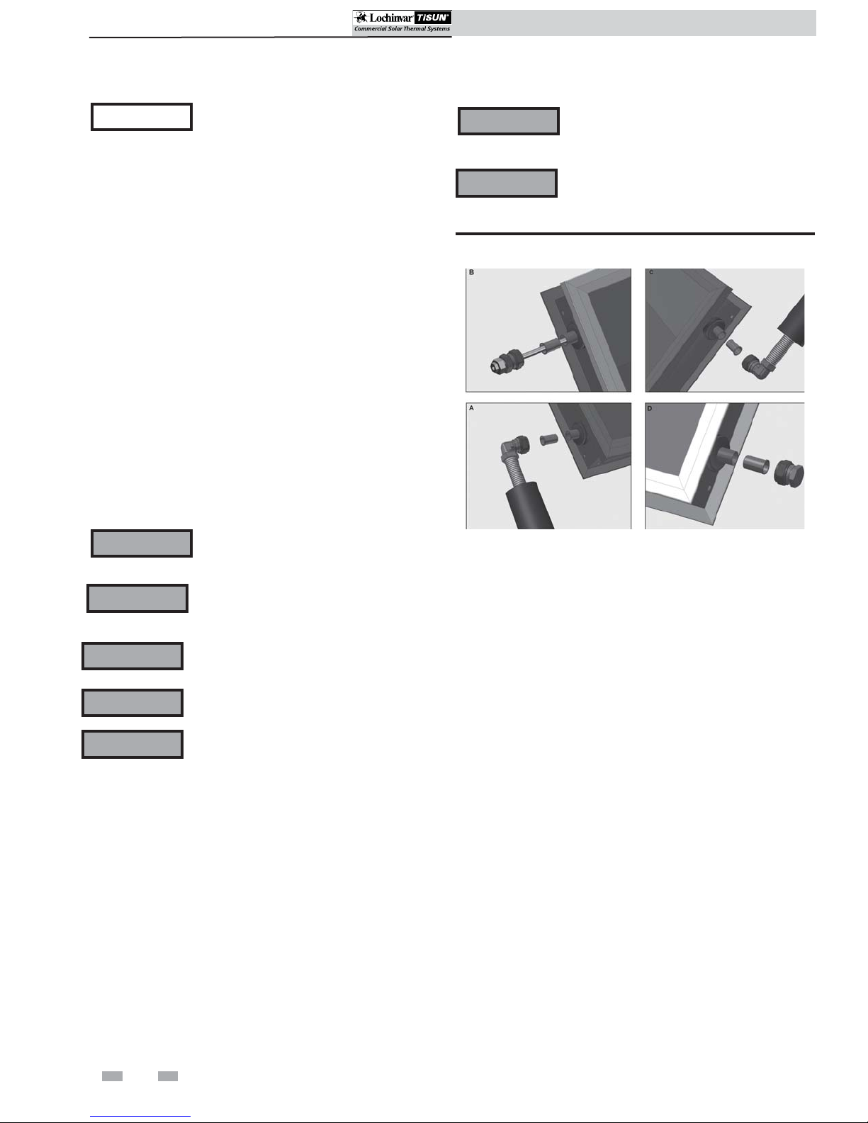
16. Install the plug, sensor well and hydraulic connections to
complete the installation (see FIG.’s 4-17, 4-18 and
4-19).
Figure 4-17 Install Plug
14. Reinstall the collector railing removed in Step 13
(FIG. 4-15).
Figure 4-15 Reinstall Collector Railing
REINSTALL COLLECTOR RAILING
OPTIONAL MECHANICAL
CONNECTION KIT
Figure 4-18 Install Sensor Well
Figure 4-19 Install Hydraulic Connections
SENSOR
WELL
EXPANSION
SET (HYDRAULIC
CONNECTION)
EXPANSION
SET (HYDRAULIC
CONNECTION)
PLUG
31
Page 32

4 Collector Installation
SCH Collectors Installation & Operation Manual
SCH Collectors Installation & Operation Manual
SCH inclined / non-south facing roof
mounting instructions
1. Install roof attachment (see the Roof Attachment Section
on pages 12 - 26 of this manual).
2. Install the horizontal bar(s) (FIG. 4-20) using the square
disk, hex bolt, and washers provided in the kit (reference
the Roof Attachment Spacing Section on page 11 of this
manual).
Figure 4-20 Install Horizontal Bars
ENDS OF HORIZONTAL BARS
MUST BE PARALLEL TO ENSURE
PROPER COLLECTOR
ORIENTATION
Figure 4-22 Drill 9 mm Hole in Horizontal Bar(s)
DRILL 9 MM HOLE TO CONNECT
A-FRAME
6. Repeat Steps 3 - 5 for each A-frame making sure all
A-frames are square and aligned with each other.
7. Install three (3) U-channel supports (FIG. 4-23). Drill a
4 mm hole through the bracket and U-channel,
use pop rivets to attach the U-channels perpendicular to
the A-frame.
3. Assemble A-frame.
4. Position A-frame to horizontal bars within 6" of the roof
attachments as shown in FIG. 4-21.
Figure 4-21 Mount A-frame to Horizontal Bars
6”
6”
Figure 4-23 Install Horizontal Supports
INSTALL HORIZONTAL
U-CHANNELS
DRILL A 4 MM HOLE THROUGH
THE BRACKET AND A-FRAME
NOTICE
Diagonal supports are needed on non-south
facing installations ONLY.
8. In the case of a non-south facing installation install
diagonal supports (see FIG. 4-24). Drill a 9 mm hole
through the support and the A-frame. Secure the
diagonal support using the bolts, washers, and nuts
provided in the kit.
Figure 4-24 Install Diagonal Supports
SECURE DIAGONAL SUPPORTS
WITH THE BOLTS, NUTS AND
WASHERS PROVIDED IN THE KIT
5. Drill a 9 mm hole through the horizontal bar(s) and A frame(s), use the bolts, washers and nuts provided in the
kit to attach the A-frame(s) to the horizontal bar(s) (see
FIG. 4-22).
32
Page 33

SCH Collectors Installation & Operation Manual
SCH Collectors Installation & Operation Manual
4 Collector Installation (continued)
9. Ensure lifting rings are installed and spaced properly per
FIG. 4-25.
Figure 4-25 Lifting Rings
< 30°
6.5 ft.
< 30°
6.5 ft.
< 30°
6.5 ft.
< 30°
8.5 ft.
Figure 4-27 Connect Collector to Bottom End Brace
CONNECT COLLECTOR
SQUARE DISK
TO BOTTOM END BRACE
HEX BOLT
13. Install the top end brace using the bolt provided in the
kit (FIG. 4-28).
14. Connect the collector to the end brace using the
square disk and bolt provided in the kit (FIG. 4-28).
15. Ensure all bolts are tightened.
Figure 4-28 Install Top End Brace
CONNECT COLLECTOR TO END BRACE
10. Position the collector onto the substructure (FIG. 4-26).
WARNING
Only loosen the crane connection when
the collectors are completely fixed to the
substructure.
Figure 4-26 Position Collector On Substructure
POSITION COLLECTOR
ONTO SUBSTRUCTURE
ENSURE .2”
OVERHANG
11. Connect the collector to the bottom end brace using the
square disk and bolt provided in the kit (FIG. 4-27). Do
not tighten.
16. For side by side installations repeat Steps 1 - 15 and
install horizontal hydraulic connections (see FIG. 4-29).
Figure 4-29 Install Horizontal Hydraulic Connections
NOTICE
The Mechanical Connection Kit is an
optional kit available through the
manufacturer.
12. Position the collector on the U-channels so that the
collector overhangs approximately 5 mm (.2") (FIG.
4-26). Tighten square disk.
33
Page 34

4 Collector Installation
SCH Collectors Installation & Operation Manual
Installation & Operation Manual
17. Remove the collector railing and install the Mechanical
Connection Kit (FIG.’s 4-30 and 4-31). Note: Be sure to
bend the tabs down on the Mechanical Connection Kit.
Figure 4-30 Remove Collector Railing
REMOVE COLLECTOR RAILING
Figure 4-31 Install Mechanical Connection Kit
BEND TABS DOWN
Figure 4-33 Install Side by Side Bracket
INSTALL SIDE BY SIDE BRACKET
20. Install the plug, sensor well and hydraulic connections to
complete the installation (see FIG.’s 4-34, 4-35 and
4-36).
Figure 4-34 Install Plug
INSTALL PLUG
18. Reinstall the collector railing removed in Step 17
(FIG. 4-32).
Figure 4-32 Reinstall Collector Railing
REINSTALL COLLECTOR RAILING
OPTIONAL MECHANICAL
CONNECTION KIT
Figure 4-35 Install Sensor Well
Figure 4-36 Install Hydraulic Connections
SENSOR
WELL
EXPANSION
SET (HYDRAULIC
CONNECTION)
19. Install the side by side bracket using the square disks and
hex bolts provided in the kit (FIG. 4-33).
34
EXPANSION
SET (HYDRAULIC
CONNECTION)
PLUG
Page 35

SCH Collectors Installation & Operation Manual
SCH Collectors Installation & Operation Manual
4 Collector Installation (continued)
SCH A-frame dimensions
Table 4A Inclined and Non-South Facing Installations
20° 6 ft. 7 in. 24 in. 6 in. 4 in.
40° 6 ft. 7 in. 47 in. 7 in. 4 in.
60° 6 ft. 7 in. 69 in. 8 in. 4 in.
ABcd
35
Page 36

4 Collector Installation
Table 4B SCH Mounting Hardware + Hydraulic Connection Kits
Installation & Operation Manual
Part-number Description
SCH065 SCH090 SCH110 SCH130
Parallel installation:
SCA20001 Horizontal aluminum bar 10 ft 2
SCA20002 Horizontal aluminum bar 13 ft 2
SCA20003 Horizontal aluminum bar 16 ft 2
SCA20004 Horizontal aluminum bar 20 ft 2
SSK20004 End bracing kit 2 2 2 2
SSK20005 Z-hook kit 2 3 3 3
Inclined (20°,40°,60°) installation:
SCA20001 Horizontal aluminum bar 10 ft 2
SCA20002 Horizontal aluminum bar 13 ft 2
SCA20003 Horizontal aluminum bar 16 ft 2
SCA20004 Horizontal aluminum bar 20 ft 2
SCA20005 Aluminum U-channel 10 ft 3
SCA20006 Aluminum U-channel 13 ft 3
SCA20007 Aluminum U-channel 16 ft 3
SCA20008 Aluminum U-channel 20 ft 3
SSK20001 A-frame 20° inclined 2 3 3 4
SSK20002 A-frame 40° inclined 2 3 3 4
SSK20003 A-frame 60° inclined 2 3 3 4
Needed quantities for:
Hydraulic connection kits: (1 array is max. 2 SCH’s!)
HYK20001 Hydr. conn. kit 2x 6.5' + plug + sensor well 1x per collector or array
HYK20002 Hydr. conn. kit 1x 6.5'/1x 13' + plug + sensor well 1x per collector or array
HYK20003 Serial hydr. exp. kit for stacked installation 1x per array
HYK20004 Parallel hydr. exp. kit for side by side installation 1x per array
HYK20005 Serial hydr. exp. kit for side by side installation 1x per array
Mechanical connection kits: (optional for installation!)
MCK20001 Mechanical conn. kit for side by side installation 1x per array
MCK20002 Mechanical conn. kit for stacked installation 1x per array
MCK20003 Cover for piping (for side by side installations) 1x per array
Gable bracing kits: (required for non-south facing installation!)
GBK20003 Bracing kit w/ diagonal support 1x per collector
36
Page 37

5 Hydraulic Connections
SCH Collectors Installation & Operation Manual
Hydraulic connection kits
The hydraulic connection kits are used to connect the collector
to the main pipework. The hydraulic connections kits
consist of two (2) flexible corrugated stainless steel pipe with
insulation, sensor well, plug and support sleeves.
Hydraulic expansion kits
The hydraulic expansion kits are hydraulic connections
between collectors in one array. The hydraulic expansion kits
consist of two (2) nipples with compression rings and unions.
Note: Hydraulic connections and expansion kits are included
with the substructure material.
WARNING
WARNING
Brazing ONLY, no soldering. When
brazing you must protect the stainless
steel connection to the copper to ensure
that the temperature does not rise above
302°F.
A properly sized expansion tank must
be used to avoid damage to the Solar
Thermal System.
Figure 5-1 SCH Hydraulic Expansion Kit
302°F
Figure 5-2 Expansion Kits - Stacked
CONNECTION EXPANSION SET, STACKED COLLECTOR IN SERIES
Description
Set for hydraulic connection of two collectors stacked, in series. Ready-to-fit corrugated
stainless-steel pipe with two (2) soldered elbow joints for .86" copper pipe. Center-tocenter distance 9 1/4". The collector outlet of the lower collector is connected to the
inlet of the upper collector. The corrugated pipe absorbs and compensates for thermal
expansion. Rubber insulation, temperature-resistant to 347°F, is fitted on the corrugated
pipe. Two plugs are included in the scope of delivery for closing the remaining header
ends. The compression ring and nut are already fitted on the collector.
NOTICE
Do not exceed 260 ft
aware of pressure drop (see the Recommended Flow Chart on page
38). Use a more powerful solar pump if necessary.
2
for the collectors connected in this way. Be
37
Page 38

5 Hydraulic Connections
Figure 5-3 Expansion Kits - Side by Side, Parallel
CONNECTION EXPANSION SET, SIDE BY SIDE, PARALLEL
Description
Set for hydraulic connection of two (2) collectors side by side. The set consists of two
(2) pieces of corrugated stainless-steel pipe with one compression ring at each end
and insulation. The headers of the left and right collectors are connected using these
corrugated stainless steel pipes. The corrugated pipe absorbs and compensates for
thermal expansion. The distance of 5.1" between the collectors must be maintained
precisely. Once the installation is complete, the insulation supplied is pulled over the
corrugated pipe and fixed in place with the adhesive tape included in the set. The
insulation is suitable for temperatures up to 347°F and resistant to UV radiation.
SCH Collectors Installation & Operation Manual
NOTICE
Figure 5-4 Expansion Kits - Side by Side, Serial
CONNECTION EXPANSION SET, SIDE BY SIDE, SERIES
Description
Set for hydraulic connection of two (2) collectors side by side, in series. Ready-to-fit
corrugated stainless-steel pipe (DN20) with two (2) soldered elbow joints for 22 mm
copper pipe. Used to make the connection side by side. The corrugated pipe absorbs
and compensates for thermal expansion. Rubber insulation, temperature resistant
to 347°F, is fitted on the corrugated pipe. Two (2) plugs are included in the scope
of delivery for closing the remaining header ends. The compression ring and nut are
already fitted on the collector.
NOTICE
Do not exceed 260 ft
(see the diagram on page 38). Use a more powerful solar pump if
necessary.
Do not exceed 260 ft
(see the diagram on page 38). Use a more powerful solar pump if
necessary.
2
of collector area. Be aware of pressure drop
2
of collector area. Be aware of pressure drop
Expansion kits that are side by side in series are known to have a high pressure drop. A pressure drop calculation is recommended.
NOTICE
If using a series connection, it is strongly recommended that a calculated pressure drop be done to ensure
proper pump installation.
38
Page 39

SCH Collectors Installation & Operation Manual
5 Hydraulic Connections (continued)
Figure 5-5 Pressure Drop Chart
MODEL NO. RECOMMENDED FLOW (GPM) PRESSURE DROP (FT OF HD)
SCH065 0.656 1.06
SCH090 0.872 1.66
SCH110 1.090 2.51
SCH130 1.300 3.59
NOTICE
The above chart references recommended flow per collector. Lochinvar recommends .01 GPM per square
foot of collector area in each array.
39
Page 40

6 System Start-up
SCH Collectors Installation & Operation Manual
Start-up
Check/control water chemistry
CAUTION
Test/replace freeze protection fluid
1. For systems using freeze protection fluids, follow fluid
manufacturer’s instructions.
2. Freeze protection fluid must be replaced periodically due
to degradation of inhibitors over time. Follow all fluid
manufacturer’s instructions.
Do not use petroleum-based cleaning
or sealing compounds in the system.
Damage to elastomer seals and gaskets
in the system could occur, resulting in
substantial property damage.
Freeze protection
1. Determine freeze protection fluid quantity using
system water content, following fluid manufacturer’s
instructions. Remember to include expansion tank
water content.
2. When using freeze protection fluid with automatic fill,
install a water meter to monitor water makeup. Freeze
protection fluid may leak before the water begins to
leak, causing concentration to drop, reducing the freeze
protection level.
3. The freeze protection set points may be lowered when
freeze protection fluid is used (see the Lochinvar Solar
Differential Control Manual).
Glycol
Aqueous solutions of Dowfrost HD fluid are designed to
provide freeze/burst and corrosion protection, as well as
efficient heat transfer, in water-based, closed-loop heating
and air-conditioning systems.
Dowfrost HD fluid has an operating temperature range of
-50°F to 325°F; with fluid freeze protection to below -60°F
and system burst protection to below -100°F. The fluid
contains corrosion inhibitors that are specially formulated
for HVAC systems to keep pipes free of corrosion without
fouling.
Thermal protection
WARNING
WARNING
WARNING
In heated water systems, a warning instruction must be
provided by the operator near the expansion tank, if persons
are endangered by excessive surface temperatures.
Thermal expansion tanks should be sized
to account for 1.5 times the solar system
circuit volume.
A properly sized expansion tank must
be used to avoid damage to the Solar
Thermal System.
The expansion tank may be hot, ensure
scalding does not occur.
WARNING
Failure to heed these instructions, especially
the safety instructions, can result in the
destruction of and defects on the expansion
tank, endanger persons, and impair the
operation.
Final checks before starting the system
Read the Lochinvar/TiSun Differential Control Installation
and Operation Manual to familiarize yourself with
differential control operation. Read this manual and follow
the proper steps to start system.
Verify the collector and system are full of water and all
system components are correctly set for operation.
Verify electrical connections are correct and securely
attached.
WARNING
All piping should be properly insulated to
avoid freezing and burn potential.
Filling, flushing and bleeding
■ There is one fill valve with hose connection for filling,
flushing and draining the solar system on both the safety
group and sensor measurement section.
■ Connect the pressure hose (forward flow) to the safety
group’s filling connection under the pressure gauge and
open fill/flush valve.
■ Connect the flushing hose (return) to the flushing
connection on the sensor measuring section and open
fill/flush valve.
■ Refer to “Operation, multi-function ball valve and check
valve” on page 38.
■ Open the supply ball valve (by turning the red
thermometer handle counter-clockwise until it stops).
■ Close return ball valve (by turning the blue thermometer
handle clockwise, until it stops).
■ If necessary, the supply and return check valve can be
opened by moving the thermometer handles to the 45°
position.
■ Put sufficient solar liquid in the tank of a filling and
flushing pump (not supplied). The mixing ratio should be
adapted to local conditions in terms of freeze protection.
■ Fill the solar system via the filling and flushing pump and
then flush the solar circuit for at least 15 min. to purge all
of the air out of the circuit.
■ Close the fill/flush valve (return) with the filling and
flushing pump running and increase the system pressure
to 60 psi. The system pressure can be read at the pressure
gauge.
40
Page 41

6 System Start-up (continued)
SCH Collectors Installation & Operation Manual
■ Close the fill/flush valve (forward flow) and switch off the
filling and flushing pump.
■ Open return ball valve (by turning the blue thermometer
handle 90° counter-clockwise until it stops).
■ The solar system features an air separator. Open the
bleeder valve until the solar liquid exits free of air bubbles.
■ Only if collector bleeder is installed: Bleed the system on
the collector until the solar liquid exits free of bubbles.
■ If necessary, increase the test pressure again to 60
psi and check the system for leaks. If the pressure gauge
shows the pressure dropping substantially, you have a leak
in the system.
■ Set the operating pressure to 60 psi as prescribed by the
system manufacturer.
■ Start up the circulation pump at maximum speed and
allow liquid to circulate for at least 15 min.
■ Remove the filling station hoses and screw the caps on the
flushing and filling valves.
■ Check the system again for leaks. Use the red and blue
thermometer handles to fully open the forward flow and
return ball valves.
Flat seal screw connections
■ All pre-fitted solar station screw connections are firmly
tightened in the factory so that they do not need to be
retightened.
Torque levels when tightening flat seal screw connections
using AFM 34 flat seals, s = 2mm.
– 3/4" screw connection 26 Ft. lb
– 1" screw connection 40 Ft. lb
– 1 1/4" screw connection 66 Ft. lb
– 1 1/2" screw connection 96 Ft. lb
Operation, multi-function ball valve and
check valve
■ The forward flow ball valve must be open for filling, flushing
and bleeding solar systems with a filling and flushing pump.
The return ball valve should be closed.
■ Both flow checks should be opened in order to bleed the
solar system (thermometer handles in 45° position).
■ The two mult-function ball valves must be fully open in
order to bleed the solar system (turn the red and blue
thermometer handles counter-clockwise until the stop is
reached).
■ Activate speed control on solar control unit. The highest
speed level should be set on the pump (phase control).
Note: The minimum speed set on the solar control unit must
not fall below the pump’s minimum nominal speed. Note
instructions for pump and solar control unit.
■ Once the installation settings have been completed and
checked, fit the solar station’s front insulation shell.
■ Refer to the collector manufacturer’s recommendations for
minimum flow requirements.
Clamp ring screw connections
■ Cut the copper pipe to length and deburr.
■ First, slide the clamp ring nut over the pipe, then clamp the
ring itself.
■ Insert the prepared pipe into the screw connection until its
stop is reached.
■ Tighten clamp ring nut by hand.
■ Use open-ended wrench to tighten clamp ring screw
connection (approximately 33 ft. lb.), retighten if necessary.
Figure 6-1 Forward flow multi-functioning instruments
SETTING FOR OPERATIONS,
FILLING, FLUSHING, DRAINING
FLOW CHECK CLOSED
BALL VALVE OPEN
DRAINING
FLOW CHECK OPEN
BALL VALVE 1/2 OPEN
SERVICE
BALL VALVE
CLOSED
Figure 6-2 Return multi-functioning instruments
SETTING FOR OPERATIONS
FLOW CHECK CLOSED
BALL VALVE OPEN
DRAINING
FLOW CHECK OPEN
BALL VALVE 1/2 OPEN
SERVICE, FILLING FLUSHING
BALL VALVE CLOSED
■ When tightening the clamp ring screw connection, use two
wrenches–using one wrench to prevent the pumping station
from turning.
41
Page 42

7 Maintenance
SCH Collectors Installation & Operation Manual
WARNING
WARNING
WARNING
Follow the service and maintenance
procedures given throughout this manual
and in component literature shipped
with the solar components. Failure to
perform the service and maintenance
could result in damage to the solar
system. Failure to follow directions in the
manual and component literature could
result in severe personal injury, death or
substantial property damage.
The solar heating system should be
inspected annually only by a qualified
service technician. In addition, the
maintenance and care of the solar
collection system explained in the
following pages must be performed
to assure maximum system efficiency
and reliability. Failure to service and
maintain the solar system could result in
equipment failure.
Turn off power to electrical components
before any service operation on the solar
system except as noted otherwise in this
instruction manual. Failure to turn off
electrical power could result in electrical
shock, causing severe personal injury or
death.
Fluid installation
Follow these installation procedures:
1. Clean new or lightly corroded existing systems with a 1% or
2% solution of trisodium phosphate in water prior to the
installation of industrially inhibited propylene glycol fluid.
2. Extensively corroded existing systems should be cleaned by
an industrial cleaning company and all corroded
components should be replace.
3. Use only quality water in solution with the propylene
glycol fluid. Use water with low levels (less than 25 ppm) of
chloride and sulfate, and less than 50 ppm of hard water
ions (Ca++, Mg++). Distilled or deionized water is
recommended.
System design considerations
Avoid use of automatic water make-up systems to prevent
undetected dilution of the propylene glycol and possible
contamination of the water system.
Technical data
Typical Properties of Dowfrost HD Fluid*
Composition (% by weight)
Propylene Glycol 94
Performance Additives 6
These maintenance items must be performed annually to
ensure proper operation of the solar collection system.
Address reported problems
1. Inspect any problems reported by the owner and correct
before proceeding.
Color Fluorescent Yellow
Specific Gravity
15/15°C (60/60°F) 1.053 - 1.063
pH of Solution
(50% glycol) 9.5 - 10.5
Reserve Alkalinity (min.) 15.0 ml
*Typical properties, not to be construed as specifications.
Complete sales specifications are available on request.
Freezing and boiling points of Aqueous Solutions
Freezing
Temperature, °F
26 10 212
19 20 213
8 30 216
-7 40 219
% Glycol
by Volume
Boiling
Temperature, °F
-28 50 222
42
Page 43

7 Maintenance (continued)
Typical properties of Aqueous Solutions+
(Glycol percentage by volume)
SCH Collectors Installation & Operation Manual
Physical
Property
Thermal
Conductivity
Btu/(hr•ft
Specific Heat,
2
)(°F/ft)
Btu/(lb•°F)
Viscosity,
Centipoise
Density,
(lb/ft3)
Temp.
°F
40 0.247 0.225 0.204
180 0.279 0.249 0.221
325 0.268 0.238 0.210
40 0.894 0.847 0.794
180 0.947 0.916 0.878
325 1.002 0.987 0.965
40 5.75 9.63 14.28
180 0.68 0.85 1.08
325 0.31 0.39 0.40
40 65.30 66.03 66.68
180 62.60 63.09 63.50
325 57.89 58.18 58.41
30% Glycol
Solution
Solar circuit
1. Verify all system components are correctly installed
and operational.
2. Check for leaks - inspect all water lines for signs of
leakage and correct any problems found.
40% Glycol
Solution
50% Glycol
Solution
Collector
1. Visually inspect the collectors to ensure that they are in
proper working condition.
2. Visually inspect the collector substructure to ensure that
no components have become loose or disconnected.
3. Check System Pressure - monitor system pressure as the
circuit heats up (during testing) to ensure that the
pressure does not rise above the designed system
pressure. Excessive pressure rise indicates expansion
tank sizing or performance problems. See the expansion
tank manufacturer’s instruction manual for required
maintenance. See the expansion tank manufacturer
recommendations for sizing and pressure settings.
4. Check Relief Valve - Inspect the relief valve and lift the
lever to verify flow.
WARNING
5. Check Freeze Protection Fluid - ensure that the heat
transfer fluid has the proper concentration of glycol as
recommended in this manual.
6. Remove any air that may have accumulated in the
system.
7. Check Flow Rate - ensure that the minimum
recommended flow rate can be achieved as described in
this manual.
Before operating any relief valve ensure
that it is piped with its discharge in a safe
area to avoid severe scald potential.
3. Visually inspect the collector piping to ensure that there
are no leaks.
4. Visually inspect roof penetrations to ensure that
environmental elements can not enter the building.
5. Visually inspect the piping insulation to ensure the
proper orientation around piping.
Pump / control function
1. Check to ensure that the pump station is in working order
and creates the minimum flow recommended in this
manual.
2. Check control sensors to ensure that they are fully inserted
into the appropriate sensing well.
3. See pump manufacturer’s recommendation for required
maintenance procedure.
Control settings
1. Check sensor readings to ensure that the values being
displayed are accurate.
2. Check control settings to ensure that they are programmed
per the control specification.
8. Visually inspect the dirt separator (if installed) and clean
if necessary.
3. See controller manufacturer’s recommendations for the
required maintenance procedure.
43
Page 44

Revision Notes: Revision A (ECO #C06510) initial release.
SCH-I-O Rev A
9/10
 Loading...