

Page 1
SYNC-MODB Rev C
MODBUS COMMUNICATION
INSTRUCTIONS
SYNC Models: 1.0 - 1.3 - 1.5
WARNING
This manual must only be used
by a qualifi ed heating installer /
service technician. Read all
instructions, including this manual,
the Installation and Operation
Manual, and the Service Manual,
before installing. Perform steps in
the order given. Failure to comply
could result in severe personal
injury, death, or substantial property
damage.
Save this manual for future reference.
Page 2

Contents
1. INTRODUCTION
Defi nitions .................................................................... 2
Minimum System Requirements .................................. 2
2. CONFIGURATION
Addressing ................................................................... 3
Timing Specifi cations ................................................... 4
Parity ............................................................................ 4
Data Transmission Mode ............................................. 4
Modbus Board Diagnostics .......................................... 4
Internal Faults ......................................................... 4
Modbus Function Set ............................................. 5
Modbus Exception Codes ............................................ 6
3. MEMORY MAP
Primary Data Tables ..................................................... 7
SYNC Boiler Memory Map ..........................................7-8
Input Registers ........................................................ 8
Holding Registers .................................................... 8
Confi guration Bits ......................................................... 8
4. WIRING REQUIREMENTS
Physical Wiring ............................................................. 9
Typical Boiler System Wiring .................................. 12-13
5. UNIT OPERATION
Unit Operation with Modbus Communications ...... 14-17
6. TROUBLESHOOTING ........................................... 18-19
7. DIAGRAMS
Ladder Diagram Part 1 & 2 .................................... 20-21
Wiring Diagram ............................................................ 22
Revision Notes ................................................... Back Cover
1 Introduction
The information contained in this manual provides general guidelines for the implementation of Modbus communication with
the Lochinvar SYNC boiler.
All Modbus networks are implemented utilizing a master-slave arrangement where all SYNC boilers are slaves and the master is
a building automation system capable of communicating over a RS-485 serial connection.
Defi nitions
Abbreviation or Acronym Meaning
ASCII American Standard Code for Information Interchange
BAS Building Automation System
Baud (Baud Rate) Number of data bits transmitted per second (bps)
EMS Energy Management System
FDX Full-Duplex
HDX Half-Duplex
Hex Hexadecimal Number (0 - 9, A - F)
I/O Box Input/Output (I/O)
LSB Least Signifi cant Byte
Modbus® A serial, half-duplex data transmission protocol developed by AEG Modicon
MSB Most Signifi cant Byte
RS232
RS485 A standard for serial transmission of data based on the RS-485 Standard
A standard for serial, full-duplex (FDX) transmission of data based on the
RS232 Standard
RTU Remote Terminal Unit
Minimum System Requirements
• BAS system or computer with a serial or USB port with a converter to RS-485.
• SYNC boiler equipped with Modbus communication board.
• Shielded twisted pair communication cable.
2
Page 3
Modbus Instructions
2 Confi guration
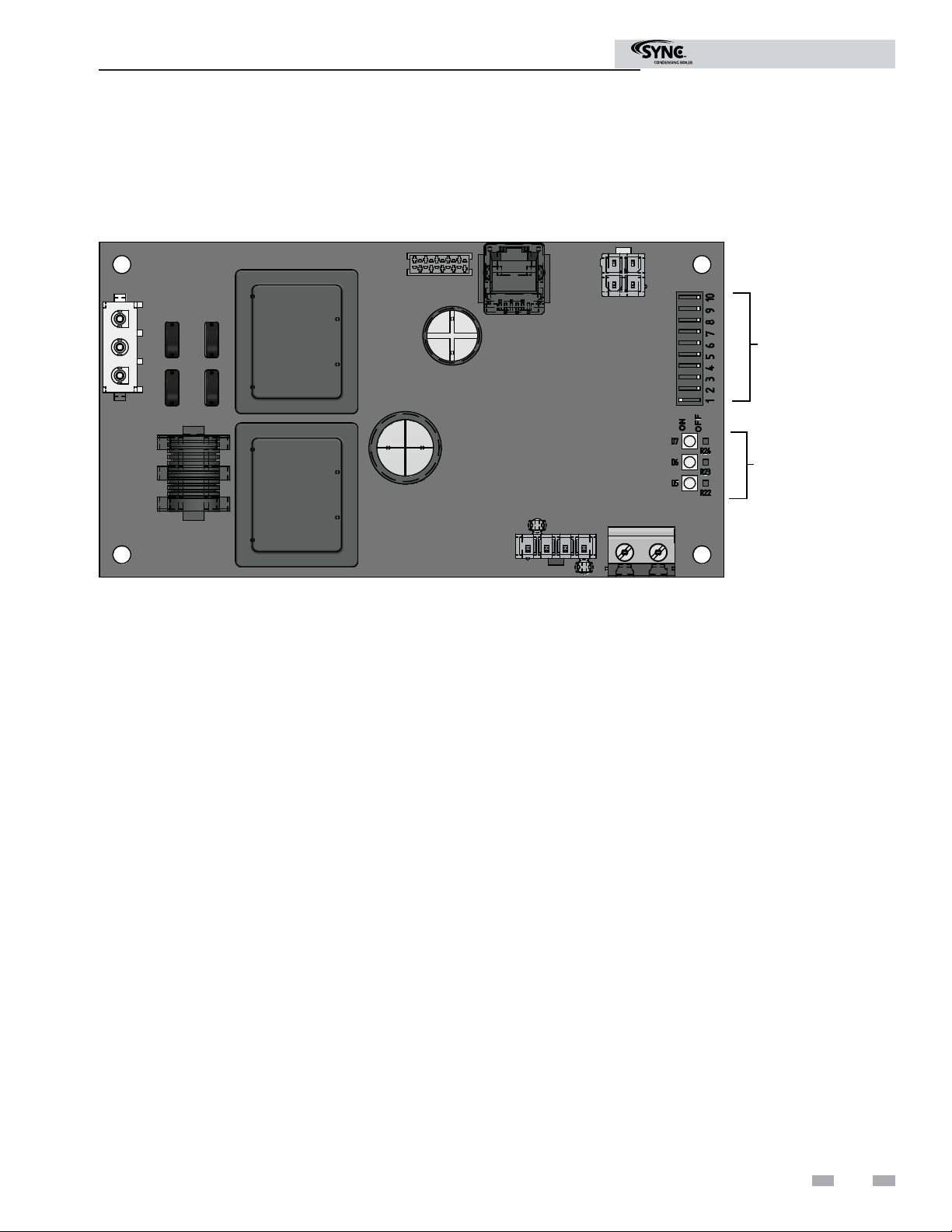
The Modbus communication board is equipped with a set of ten dip switches that are used to set the board confi guration
(address, baud rate, and parity settings). The fi rst eight are used to set the address of each board. The ninth baud rate. The
tenth is parity.
Figure 2-1_Modbus Communication Board
DIP SWITCHES
LED’S
Addressing
The Modbus addressing space is comprised of 256 different
addresss.
• 0 is reserved for broadcast messages from the master
device
• 1 - 247 are free to use for each unique device
• 248 - 255 are reserved
To set the Modbus address the dip switches can be set in
either the 0 position or the 1 position. For switches set to
the 1 position their value will be added together to determine
the address.
For each switch set to the 1 position it has the following value:
Dip switch 1 = 1
Dip switch 2 = 2
Dip switch 3 = 4
Dip switch 4 = 8
Dip switch 5 = 16
Dip switch 6 = 32
Dip switch 7 = 64
Dip switch 8 = 128
Any dip switch set to 0 has a value equal to 0.
Example:
To set the address of the Modbus board to 50, dip switches
2, 5, and 6 have to be set to the 1 position. The address is
determined by adding the values of all the dip switches together.
Address = Value of Dip switch 1 + Value of Dip switch 2 +
Value of Dip switch 3 + Value of Dip switch 4 + Value of Dip
switch 5 + Value of Dip switch 6 + Value of Dip switch 7 +
Value of Dip switch 8
In this example:
Address = 0 + 2 + 0 + 0 + 16 + 32 + 0 + 0 = 50
3
Page 4

2 Confi guration
Modbus Instructions
Timing Specifi cations
The baud rate for the Modbus board is selectable with Dip
switch #9.
1 = 19200 bps
0 = 9600 bps
Each message is started by at least 3.5 character times of
silence. The maximum delay between frames is 1.5 character
times.
When the system temperature and/or tank temperature
is provided by the BAS to the boiler, it is critical that the
temperature be updated every few seconds. If the boiler does
not receive updated temperatures within a timeout period
(installer adjustable), the control will revert to using its
own sensor inputs (if sensors are connected). The timeout
is programmable by pressing the MAIN>>SETUP>>BMS
buttons. The timeout is adjustable between 5 and 120
seconds. The default timeout is 10 seconds.
When the BAS is not providing either of these temperatures,
but is still controlling the boiler (such as providing a
modulation command), the BAS must refresh these
commands at least every 4 minutes. If the commands are
not refreshed, the boiler will revert to operating based on its
own inputs.
Parity
Parity is set by the position of Dip switch #10.
0 = No Parity
1 = Even Parity
If No Parity is selected there will be two stop bits, otherwise
there will be one.
Data Transmission Mode
Many Modbus bus master devices can be confi gured to transmit
data in either Modbus RTU or Modbus ASCII modes. Since
RTU messages can be formatted to use fewer data bits and are
therefore more effi cient, RTU has been chosen to be used with
all Lochinvar Modbus communication. Please ensure that the
master device is transmitting Modbus RTU.
Modbus Board Diagnostics
The Modbus board is equipped with three LED’s for visual
diagnostics: Two yellow LED’s and one green. One yellow LED
(D5) is used to indicate reception of data. The other yellow
LED (D6) is used to indicate transmission of data. The green
LED (D7) is used to show internal faults.
Internal Faults:
Normal Operation = 1 second on, 1 second off
Controller Fault = Continuously on
No Burner Control Communication = 0.5 seconds on, 1.5
seconds off
No Modbus Communication = 1.5 seconds on, 0.5 seconds
off
Modbus Communication
The Modbus communication commands and exception codes
that are supported by the Modbus communication board can
be found on pages 5 and 6 of this manual.
4
Page 5

2 Confi guration (continued)
Modbus Function Set
Modbus Instructions
Function Sub Function
HEX Description
Dec HEX Dec
1 01 Read Coil Status
2 02 Read Input Status
3 03 Read Holding Registers
4 04 Read Input Registers
5 05 Force Single Coil
6 06 Preset Single Register
7 07 Read Exception Status
8 08 0 00 Diagnostic - Return Query Data
1 01 Diagnostic - Restart Communication
2 02 Diagnostic - Return Diagnostic Register
4 04 Diagnostic - Force Listen Mode
10 0A
11 0B Diagnostic - Return Bus Message Count
Diagnostic - Clear Counters and Diagnostic
Registers
12 0C Diagnostic - Bus Communication Error Count
13 0D Diagnostic - Bus Exception Error Count
14 0E Diagnostic - Return Slave Message Count
15 0F Diagnostic - Return Communication Error Count
16 10 Diagnostic - Return Slave NAK Count
17 11 Diagnostic - Return Slave Busy Count
18 12 Diagnostic - Return Bus Character Overrun Count
20 14 Diagnostic - Clear Overrun Counter and Flag
11 0B Get Communication Event Counter
12 0C Get Communication Event Log
15 0F Write Multiple Coils
16 10 Write Multiple Registers
17 11 Report Slave ID
23 17 Read / Write Multiple Registers
5
Page 6

2 Confi guration
Modbus Exception Codes
MODBUS Exception Codes
Code Name Meaning
The function code received in the query is not an allowable action for the server
(or slave). This may be because the function code is only applicable to newer
01 ILLEGAL FUNCTION
02 ILLEGAL DATA ADDRESS
devices, and was not implemented in the unit selected. It could also indicate that
the server (or slave) is in the wrong state to process a request of this type, for
example because it is unconfi gured and is being asked to return register values.
The data address received in the query is not an allowable address for the
server (or slave). More specifi cally, the combination of reference number and
transfer length is invalid. For a controller with 100 registers, the PDU addresses
the fi rst register as 0, and the last one as 99. If a request is submittted with a
starting register address of 96 and a quantity of registers of 4, then this request
will successfully operate (address-wise at least) on registers 96, 97, 98, 99. If
a request is submitted with a starting register address of 96 and a quantity of
registers of 5, then this request will fail with Exception Code 0x02 “Illegal Data
Address” since it attempts to operate on registers 96, 97, 98, 99 and 100, and
there is no register with address 100.
Modbus Instructions
03 ILLEGAL DATA VALUE
04 SLAVE DEVICE FAILURE
05 ACKNOWLEDGE
06 SLAVE DEVICE BUSY
08 MEMORY PARITY ERROR
A value contained in the query data fi eld is not an allowable value for server
(or slave). This indicates a fault in the structure of the remainder of a complex
request, such as that the implied length is incorrect. It specifi cally does NOT
mean that a data item submitted for storage in a register has a value outside the
expectation of the application program, since the MODBUS protocol is unaware of
the signifi cance of any particular value of any particular register.
An unrecoverable error occurred while the server (or slave) was attempting to
perform the requested action.
Specialized use in conjunction with programming commands. The server (or
slave) has accepted the request and is processing it, but a long duration of time
will be required to do so. This response is returned to prevent a timeout error from
occurring in the client (or master). The client (or master) can next issue a Poll
Program Complete message to determine if processing is completed.
Specialized use in conjunction with programming commands. The server (or
slave) is engaged in processing a long -- duration program command. The client
(or master) should re-transmit the message later when the server (or slave) is free.
Specialized use in conjuction with function codes 20 and 21 and reference type
6, to indicate that the extended fi le area failed to pass a consistency check. The
server (or slave) attempted to read record fi le, but detected a parity error in the
memory. The client (or master) can retry the request, but service may be required
on the server (or slave) device.
0A GATEWAY PATH UNAVAILABLE
0B
GATEWAY TARGET DEVICE
FAILED TO RESPOND
6
Specialized use in conjunction with gateways, indicates that the gateway was
unable to allocate an internal communication path from the input port to the
output port for processing as the request. Usually means that the gateway is
misconfi gured or overloaded.
Specialized use in conjunction with gateways, indicates that no response was
obtained from the target device. Usually means that the device is not present on
the network.
Page 7
Modbus Instructions
3 Memory Map
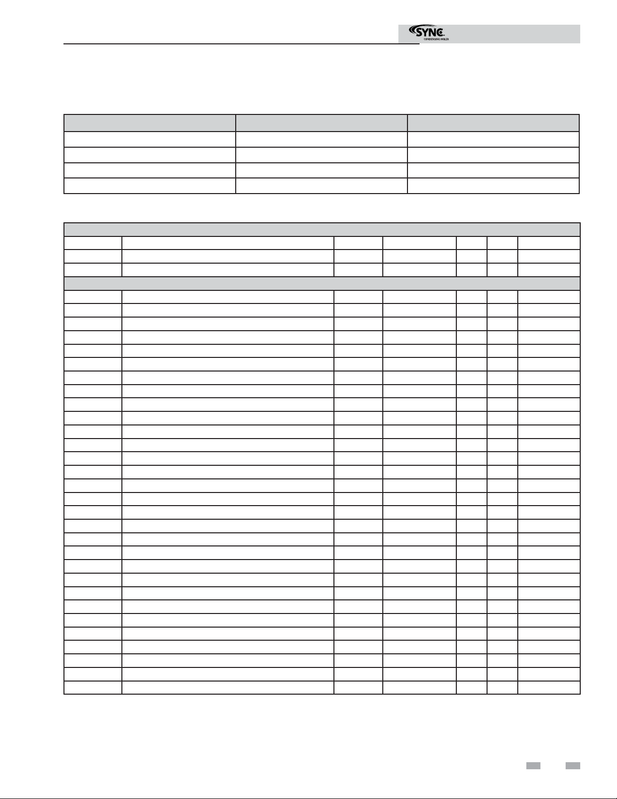
Primary Data Tables
Table Data Type Read / Write
Discrete Inputs Single Bit Read Only
Coils Single Bit Read / Write
Input Registers 16-Bit Word Read Only
Holding Registers 16 Bit Word Read / Write
SYNC Boiler Memory Map
Coils
Address Description Default Unit Min. Max. Resolution
00001 Boiler Enable / Room Thermostat 1 / Stage 1 0 1=ON / 0=OFF 0 1 1
00005 Tank Thermostat 0 1=ON / 0=OFF 0 1 1
Discrete Inputs
10001 Manual Reset High Limit 1 0 1=ON / 0=OFF 0 1 1
10002 Flow Switch 1 0 1=ON / 0=OFF 0 1 1
10003 Gas Pressure Switch 1 0 1=ON / 0=OFF 0 1 1
10004 Louver Proving Switch 1 0 1=ON / 0=OFF 0 1 1
10005 Air Pressure Switch / Flap Valve 1 0 1=ON / 0=OFF 0 1 1
10006 Blocked Drain Switch 1 0 1=ON / 0=OFF 0 1 1
10007 Auto Reset High Limit 1 0 1=ON / 0=OFF 0 1 1
10008 Flame 1 0 1=ON / 0=OFF 0 1 1
10009 Enable / Room Thermostat 1 / Stage 1 0 1=ON / 0=OFF 0 1 1
10010 Tank Thermostat 0 1=ON / 0=OFF 0 1 1
10017 Manual Reset High Limit 2 0 1=ON / 0=OFF 0 1 1
10018 Flow Switch 2 0 1=ON / 0=OFF 0 1 1
10019 Gas Pressure Switch 2 0 1=ON / 0=OFF 0 1 1
10020 Louver Proving Switch 2 0 1=ON / 0=OFF 0 1 1
10021 Air Pressure Switch / Flap Valve 2 0 1=ON / 0=OFF 0 1 1
10022 Blocked Drain Switch 2 0 1=ON / 0=OFF 0 1 1
10023 Flame 2 0 1=ON / 0=OFF 0 1 1
10033 Run-time Contacts 0 1=ON / 0=OFF 0 1 1
10034 Alarm Contacts 1 0 1=ON / 0=OFF 0 1 1
10035 CH Pump 1 0 1=ON / 0=OFF 0 1 1
10036 DHW Pump 1 0 1=ON / 0=OFF 0 1 1
10038 Gas Valve 1 0 1=ON / 0=OFF 0 1 1
10039 System Pump 0 1=ON / 0=OFF 0 1 1
10041 Run-time Contacts 2 0 1=ON / 0=OFF 0 1 1
10042 Alarm Contacts 2 0 1=ON / 0=OFF 0 1 1
10043 CH Pump 2 0 1=ON / 0=OFF 0 1 1
10046 Gas Valve 2 0 1=ON / 0=OFF 0 1 1
7
Page 8
Modbus Instructions
3 Memory Map
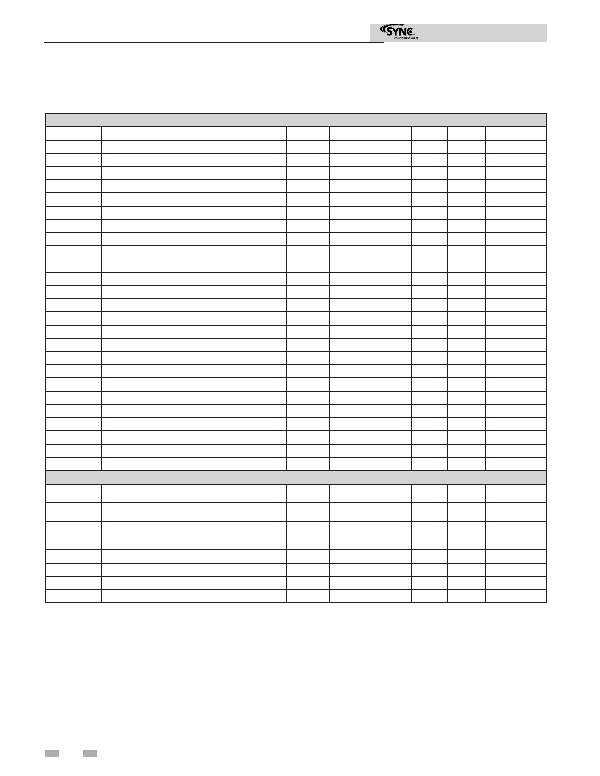
SYNC Boiler Memory Map
Input Registers
Address Description Default Unit Min. Max. Resolution
30001 Discrete Inputs 1 - 16 0 NA 0 65535 1
30002 Discrete Inputs 17 - 32 0 NA 0 65535 1
30003 Discrete Inputs 33 - 48 0 NA 0 65535 1
30004 System / Cascade Setpoint 0 Degrees Celsius 0 130 0,5
30006 Cascade Total Power 0 % 100 800 1
30007 Cascade Current Power 0 % 0 800 1
30008 Outlet Setpoint 1 0 Degrees Celsius 0 130 0,5
30009 Outlet Temperature 1 0 Degrees Celsius 0 130 0,1
30010 Inlet Temperature 1 0 Degrees Celsius -20 130 0,1
30011 Flue Temperature 1 0 Degrees Celsius -20 130 0,1
30012 Firing Rate 1 0 % 0 100 1
30014 Boiler 1 Status Code 0 NA 0 65535 1
30015 Boiler 1 Blocking Code 0 NA 0 65535 1
30016 Boiler 1 Lockout Code 0 NA 0 65535 1
30017 Outlet Setpoint 2 0 Degrees Celsius 0 130 0,5
30018 Outlet Temperature 2 0 Degrees Celsius 0 130 0,1
30019 Inlet Temperature 2 0 Degrees Celsius -20 130 0,1
30020 Flue Temperature 2 0 Degrees Celsius -20 130 0,1
30021 Firing Rate 2 0 % 0 100 1
30023 Boiler 2 Status Code 0 NA 0 65535 1
30024 Boiler 2 Blocking Code 0 NA 0 65535 1
30025 Boiler 2 Lockout Code 0 NA 0 65535 1
Holding Registers
40001 Confi guration 0 NA 0 65535 1
40002 Coils 0 NA 0 65535 1
40003
40004 Tank Setpoint 0 Degrees Celsius 0 87,5 0,5
40005 Tank Temperature 0 Degrees Celsius -20 130 0,1
40006 Outdoor Temperature 0 Degrees Celsius -40 60 0,1
40007 System Supply Temperature 0 Degrees Celsius -20 130 0,1
0-10 Volt Input / Rate Command / Setpoint
Command
0 % 0 100 1
Confi guration Bits
Address 40001 contains confi guration bits sent from the BAS to the boiler. These bits tell the boiler to use its own internal inputs,
or inputs from the BAS. When a bit is set to 1, the boiler will ignore the corresponding value contained internally, and expect
the BAS to write that value into the Holding Registers. The confi guration bits are as follows:
Bit 0 (LSB): Boiler Enable
Bit 1: Tank Thermostat
Bit 2: Rate Command / 10 - 10V Input / Setpoint Command
Bit 3: Tank Setpoint
8
Bit 4: System Supply Temperature
Bit 5: Outdoor Temperature
Bit 6: Tank Temperature
Bit 7: System Return Temperature
Bit 8 - 15: Not Used (Default = 0)
Page 9

Modbus Instructions
4 Wiring Requirements
Note that when the System Supply Temperature and/or the Tank Temperature are provided by the BAS, they need to be refreshed
every few seconds. This is required in order to prevent unwanted fl uctuations in these temperatures. If these values are not
provided every few seconds (timeout is programmable), the boiler will revert to its own internal control. If neither of these
temperatures is provided by the BAS, but any of the other control signals are being provided, the BAS will still need to refresh
these inputs at least every 4 minutes.
Physical Wiring
RS-485 Communication Bus
• Maximum Length = 4000 feet
• Cable Specifi cation = 24 AWG / A,B (twisted pair) and GND Shielded, with characteristic Impedance = 120 ohm
• Maximum Load = 32 units (32 nodes)
NOTE: Cable must be terminated with 120 ohm impedance matching resistor on each end.
Figure 4-1_Terminal Strip Connections
MOD BUS
LBL20052 REV B
1 ALARM
2 CONTACTS
SHIELD
B
A
7 HEX 2
3 RUN TIME
8 FLOW SWITCH
4 CONTACTS
5 LOUVER
6 PROVING
9 HEX 1
ENABLE
13 R
11 TANK
12 THERMOSTAT
10 FLOW SWITCH
14 W
18 SHIELD GND
16 A
15 SHIELD GND
17 B
0 - 10V INPUT
21 SYSTEM
22 SENSOR
20 (-)
19 (+)
23 OUT DOOR
CASCADE
24 SENSOR
26 SENSOR
25 TANK
27 SHIELD GND
28 B
30 SHIELD GND
29 A
SHIELD
MODBUS COMMUNICATION BUS
TO NEXT BOILER
B
A
SHIELD
TO NEXT BOILER
A
B
A
B
SHIELD
BUILDING
MANAGEMENT
SYSTEM
LOUVER
PROVING
SWITCH
HEAT
EXCHANGER 2
FLOW SWITCH
HEAT
EXCHANGER 1
FLOW SWITCH
TANK
FROM PREVIOUS BOILER
THERMOSTAT
ENABLING DEVICE
SYSTEM SENSOR
OUTDOOR SENSOR
TANK SENSOR
9
Page 10

4 Wiring Requirements
R
Figure 4-2_Control Inputs
LOW VOLTAGE
CONNECTION
BOARD
SMART TOUCH
CONTROL MODULE
SEQUENCER / BUILDING
MANAGEMENT SYSTEM
PRIMARY
Modbus Instructions
SECONDARY
SMART TOUCH
CONTROL MODULE
OUTDOOR SENSOR
HW TANK SENSOR
SYSTEM SENSOR
FLOW SWITCH
HW THERMOSTAT
ROOM THERMOSTAT /
ZONE CONTROL
BLOCKED DRAIN SWITCH
LOW WATER CUTOFF
TOUCH DISPLAY
PC INTERFACE
TOUCH PANEL
INTERFACE
MODBUS COMMUNICATION
HEAT EXCHANGER 1 /
HEAT EXCHANGER 2 INLET
TEMPERATURE SENSOR
HEAT EXCHANGER 1 /
HEAT EXCHANGER 2 OUTLET
TEMPERATURE SENSOR
HEAT EXCHANGER 1 /
HEAT EXCHANGER 2 FLUE GAS SENSOR
GAS PRESSURE SWITCH
HEAT EXCHANGER 1 /
HEAT EXCHANGER 2 HIGH LIMIT SENSO
FLAME SENSOR
BOARD
10
Page 11

4 Wiring Requirements (continued)
Figure 4-3_Control Outputs
Modbus Instructions
SECONDARY
LOW VOLTAGE
CONNECTION
BOARD
ALARM BELL
RUN TIME CONTACTS
SMART TOUCH
CONTROL MODULE
PRIMARY
SMART TOUCH
CONTROL MODULE
SEQUENCER / BUILDING
MANAGEMENT SYSTEM
SYSTEM PUMP
TOUCH DISPLAY
PC INTERFACE
TOUCH PANEL
INTERFACE
HEAT EXCHANGER 1 /
HEAT EXCHANGER 2
BOILER PUMP
HW PUMP
IGNITOR
BLOWER
GAS VALVE
11
Page 12

4 Wiring Requirements
Figure 4-4_Control Location
CONTROLLER 2
CONTROLLER 1
MODBUS
COMMUNICATION
BOARD (MTR01)
HEAT EXCHANGER 1
HEAT EXCHANGER 2
Modbus Instructions
Typical Boiler System Wiring
Physical Configuration: Cascade without Individual Monitoring
Modbus RS485 Port on Gateway or Building System
Modbus RS485 Communication Bus
Cascade Daisy Chain Connection
12
Page 13

4 Wiring Requirements (continued)
Physical Configuration: Direct Control
Physical Configuration: Cascade with individual Monitoring
Modbus RS485 Port on Gateway or Building System
Modbus RS485 Communication Bus
Modbus Instructions
Cascade Daisy Chain Connection
Modbus RS485 Port on Gateway or Building System
Modbus RS485 Communication Bus
13
Page 14

Modbus Instructions
5 Unit Operation
Unit Operation with Modbus Communications
To control a SYNC boiler through a Building Management System communicating through Modbus, the SYNC Demand
Confi guration must be set to a value of 4, 5, or 6. These confi gurations allow different control points for a variety of applications.
The confi guration can be set by selecting Main>>Setup>>Service/Setup>>Demand Confi g.
Figure 5-1_Setup Screen
The SYNC boiler is equipped with a Modbus communication timer. This timer is programmable from 0 - 120 seconds. The
timer can be programmed from the Modbus Setup Menu by selecting Main>>Setup>>BMS>>Modbus Timeout. The purpose
of the timer is to ensure proper temperature data is communicated to the boiler in a timely manner. Additionally, it will provide
for fail safe operation should Modbus communication be lost. This timer will cause the unit to revert back to internal unit
controls should the Modbus communication be interrupted longer than the Modbus timer. The timer is reset every time a
Modbus write command is received with updated temperatures or commands. It is the recommendation of Lochinvar that this
timer be set to the shortest value possible.
When controlling a SYNC boiler through a Building Automation System (BAS), it is very important to ensure that the correct
confi guration bits are sent to holding register 40001, and that the correct data and enable signals are sent to holding registers
40002 - 40007, per the demand confi guration.
Demand Confi guration 4
In this confi guration the unit is controlled by setting the setpoints locally on the boiler and providing an enable signal through
Modbus communications.
All sensors and limiting devices should be hardwired to the terminal strip on the back of the unit excluding the thermostat enable
and tank thermostat enable signal. These signals will be sent to the unit via Modbus.
The holding registers will need to be set as follows:
Holding Registers Defi nition Bit Value (HEX) Action
40001 Confi guration 00 01 Set Confi guration to read 40002
40002 Coils 00 01 Enables unit (00 00 disables unit)
NOTE: To ensure proper operation re-send the confi guration bits to holding register 40001 prior to issuing a command.
14
Page 15

Modbus Instructions
5 Unit Operation (continued)
Demand Confi guration 5
In this confi guration the unit is controlled by providing an enable signal and a rate command through Modbus communications.
The rate command will be 0 - 100% of modulation.
All sensors and limiting devices should be hardwired to the terminal strip on the back of the unit excluding the thermostat enable
and tank thermostat enable signal. These signals will be sent to the unit via Modbus.
The holding registers will need to be set as follows:
Holding Registers Defi nition Bit Value (HEX) Action
40001 Confi guration 00 05 Set Confi guration to read 40002 & 3
40002 Coils 00 01 Enables unit (00 00 disables unit)
40003 Rate Command 00 ## Sets Modulation % or Setpoint
NOTE: To ensure proper operation re-send the confi guration bits to holding register 40001 prior to issuing a command.
For proper hexadecimal conversion of rate percentage, please refer to the Rate and Temperature Conversion section on page 17
of this manual.
Demand Confi guration 6
In this confi guration the unit is controlled by setting the modulation setpoint from 0 - 100%.
Rate command will be 0 - 100% of the modulation range.
All sensors and limiting devices should be hardwired to the terminal strip on the back of the unit excluding the 0 - 10Vdc signal.
This signal will be sent to the unit via Modbus.
The holding registers will need to be set as follows:
Holding Registers Defi nition Bit Value (HEX) Action
40001 Confi guration 00 04 Set Confi guration to read 40003
40003 Rate Command 00 00 Sets Modulation %
NOTE: To ensure proper operation re-send the confi guration bits to holding register 40001 prior to issuing a command.
For proper hexadecimal conversion of rate percentage, please refer to the Rate and Temperature Conversion section on page 17
of this manual.
Hot Water Generation
Hot water generation can be accomplished with one of two methods when a SYNC boiler is connected to a BAS system, DHW
with direct control, and DHW with remote control.
DHW with direct control:
This is the typical installation with a hot water generator in close proximity to the boiler with the tank thermostat, or tank
temperature sensor, wired to the terminal strip of the unit.
15
Page 16

Modbus Instructions
5 Unit Operation
DHW with remote control:
This installation may or may not have the hot water generator in close proximity to the boiler. Its sensors and thermostat values
are only available through the Modbus communication bus.
To ensure that the SYNC boiler can properly respond to a call for hot water generation the following holding registers must be
set in addition to other commands:
Holding Registers Defi nition Bit Value (HEX) Action
40001 Confi guration 00 4A Set Confi guration to read 40002, 4 & 5
40002 Coils 00 08 Enables Tank Tstat (00 00 disables unit)
40004 Tank Setpoint 0# ## Sets Setpoint
40005 Tank Temperature 0# ## Passes tank temp from remote sensor
NOTE: To ensure proper operation re-send the confi guration bits to holding register 40001 prior to issuing a command.
For proper hexadecimal conversion of rate percentage, please refer to the Rate and Temperature Conversion section on page 17
of this manual.
Cascade
In order to operate the SYNC boiler in Cascade with Modbus
communications, confi gure the leader boiler per the demand
confi gurations in this manual. Connect the remaining boilers
in the cascade through the normal cascade communications
wiring. Cascade control can then be accomplished
automatically through the leader boiler.
Please note that with Modbus communication connected to
only the leader boiler, total Cascade information can be seen
through the communications link. If you wish to see all the
individual temperatures of each unit in the Cascade, each unit
will have to have a Modbus communication board. However,
each unit can be monitored without the need to control each
one individually.
Monitoring Only
Any SYNC boiler can be equipped with the Modbus
communication board and then be set up to operate with its
own internal controls. If necessary, Modbus can be confi gured
as a monitoring device by selecting demand confi gurations 1 - 3,
and polling the Modbus board for the read only variables.
16
Page 17

5 Unit Operation (continued)
Modbus Instructions
Rate and Temperature Conversions:
Rate
When issuing a rate command the rate can be communicated
as percent modulation or a desired setpoint, depending on
the setting of the BMS Type in the BMS Setup Menu.
The proper data format for the modulation percentage is the
direct conversion to hexadecimal. This conversion can be
accomplished through online number based converters or
some scientifi c calculators.
For Example:
Rate % HEX
000
20 14
45 2D
60 3C
80 50
95 5F
100 64
To send a desired setpoint, the hexadecimal value must be
determined through linear interpolation of programmable
parameters on the BMS Setup Menu:
- BMS temperature set-point at low analog input
- BMS temperature set-point at high analog input
These variables set the temperature values corresponding to
the minimum and maximum voltage settings of the 0-10 volt
signal. The defaults are as follows:
PARAMETER
BMS temperature setpoint at
low analog input
BMS temperature setpoint at
high analog input
DEFAULT
VALUES
Deg C Deg F Voltages
21 69.8 2
82 179.6 10
DEFAULT
For Example:
Send a setpoint of 110°F.
The formula to use for the interpolation is:
Rate Command =
(Desired Setpoint – BMS Temp at Low Analog Input) (High
Voltage-Low Voltage) + Low Voltage
(BMS Temp at High Analog Input – BMS Temp at Low
Analog Input)
From the default values:
Desired Setpoint = 110
BMS Temp at Low Analog Input =68
BMS Temp at High Analog=158
High Voltage =10
Low Voltage = 2
[(110-69.8)(10-2)/(179.6-69.8)] + 2 = 4.92 Volts
(4.92/10) x 100 = 49.2
49 = 31 Hexadecimal
A value of [00][31] in hexadecimal would be written to Holding
register 40003 to issue a command for a 110°F setpoint.
Temperature
The SYNC boiler passes temperature data in degrees Celsius.
Also, to accommodate decimal places the decimal value must
be divided by 10.
Here are the conversions to and from Celsius:
T
Example:
Outdoor temperature from remote sensor on BAS System = 80°F
80°F = 26.7°C
Data that needs to be transmitted is 26.7 * 10 = 267
c
= (5/9) * (Tf-32) Tf = (9/5) * Tc+32
Decimal Binary HEX
267 100001011 10B
Outlet temperature from unit sensor = 155°F
155°F = 68.3°C
Data transmitted from unit in HEX = 2AB = 683
683 ÷ 10 = 68.3 (°C)
Decimal Binary HEX
683 1010101011 2AB
17
Page 18

6 Troubleshooting
Modbus Instructions
Should you encounter problems communicating over
Modbus, the following items should be checked in this order:
1. Physical Layer
2. Communications Confi guration and Port Settings
3. Modbus Error Codes
4. Unit Status / Blocking / Lockout Codes
Physical Layer
1. Check that all components have power (Boiler, Gateway,
BAS Master)
2. Check all wire lengths. Are any drops too long?
3. Check proper shield grounding
4. Check A, B terminal connections
5. Check for Terminating Resistors (120 ohms)
6. Check for broken wires
Communications
1. Check Dip Switch Confi guration of MTR-01 Board
2. Check Baud Rate (9600, 19200)
3. Check Parity
4. Check Slave ID
5. Check Port Setting on Master, Gateway, and Computers
Modbus Error Codes
1. Check Modbus communication for error codes (see page
6 for Modbus Exception Codes)
2. Check Modbus PDU
3. Check Slave ID
4. Check Modbus Command
5. Check Confi guration bits for Holding Register 40001
6. Check Commands and data for Holding Registers
40002 - 40007
Unit Status Codes
See Codes in this section
Boiler Status
The SYNC boiler displays a boiler state code on the Building
Screen to help aid in troubleshooting. The boiler state
indicates what the boiler is actually doing. This state should
be compared to the command issued and what is expected.
If the boiler state does not agree with the command issued,
check communication and confi guration.
Status Codes (Input Registers 30014 and 30023)
2 = Heat Demand blocked due to high absolute outlet
temperature
3 = Heat Demand blocked due to high absolute fl ue
temperature
4 = Heat Demand blocked due to high absolute Delta T
(Outlet - Inlet)
8 = Heat Demand blocked due to Low 24 VAC
9 = Outdoor shutdown
10 = Block due to switch OFF boiler (ON/OFF of Display)
12 = Block due to no correct communication Cascade
16 = Service function
19 = DHW function Storage Tank
21 = SH function Heat demand from Room Thermostat
22 = SH function Heat demand from Boiler Management
System
23 = SH function Heat demand from Cascade
30 = Heat demand activated by Freeze Protection
32 = DHW Pump Delay
33 = SH Pump Delay
34 = No heat function (after pump delay)
40 = Lockout
32764 = Busy with updating status
32765 = DHW blocked due to no present tank sensor
32766 = Burner control(s) manually shut down
32767 = Code not present
Blocking Codes (Input Registers 30015 and 30024)
0 = No blocking _> is divided into sub blockings
1 = SH blocking
2 = Blocking Due to Low 24 VAC Supply
3 = Blocking due to General block
4 = Blocking MRHL is open
5 = Blocking due to Switched OFF boiler (Display ENTER
switch)
6 = Blocking due to wrong communication of Cascade
7 = Blocking due to High Delta
8 = Blocking due to High Flue Temperature
9 = Blocking due to High Outlet Temperature
10 = Service blocking
12 = DHW blocking high outlet temperature (DHW confi gured
as storage tank)
13 = Blocking anti-cycling time
14 = Storage Tank demand Blocked due to Fan problems
15 = No system sensor connected and leader control present
16 = Limit fan speed due to high outlet temperature
17 = Fan min decreased due to low fl ame current
18 = Limit max fan speed due to high Delta T
19 = Limit max fan speed due to high fl ue temp
32767 = Code not present
18
Page 19

6 Troubleshooting (continued)
Modbus Instructions
Lockout Codes (Input Registers 30016 and 30025)
161 = EEPROM code Parameters not Re-Programmed by
Lochinvar
164 = EEPROM code No Reset Allowed (> 15 minutes)
166 = EEPROM code Auto Reset High Limit
167 = EEPROM code Blocked Drain
168 = EEPROM code Louver Proving
169 = EEPROM code Gas Pressure Sw
170 = EEPROM code Flow Switch
177 = Sensor 3 short (Flue Sensor)
178 = Sensor 3 open (Flue Sensor)
179 = Sensor 2 short (Inlet Sensor)
180 = Sensor 2 open (Inlet Sensor)
192 = Sensor 1 short (Outlet Sensor)
193 = Sensor 1 open (Outlet Sensor)
204 = CRC EEPROM failed
205 = EEPROM programmed (display shows “PP”)
206 = EEPROM error in programming
207 = Write error EEPROM
229 = EEPROM code Watch Dog
230 = EEPROM code fan low (should be high)
231 = EEPROM code fan high (should be low)
232 = EEPROM code no fl ame when running
233 = EEPROM code no fl ame after ignition
234 = EEPROM code simultaneous output APS and Fan
235 = EEPROM code APS active not Closed
236 = EEPROM code APS active not Open
237 = EEPROM code fl ame out of sequence
239 = EEPROM code when gas valve relay test fails
240 = EEPROM code MRHL
32767 = Code not present
Installation / Replacement Procedure
1. Turn OFF the main electrical power to the appliance.
2. Turn OFF the main manual gas shutoff to the appliance.
3. Unplug the three (3) wire harnesses on the MTR01 control
board (see FIG. 6-1).
4. Unscrew the four (4) mounting nuts on the MTR01 control
board and set aside. Remove the MTR01 control board (see
FIG. 6-2).
5. Replace / install the new MTR01 control board.
6. Replace the four (4) mounting nuts removed in Step 4.
7. Reconnect all three (3) wire harnesses unplugged in Step 3.
8. Turn on the main electrical power and the main manual gas
shutoff to the appliance.
9. Confi gure the MTR01 control board and unit controls per
this manual and resume operation.
Figure 6-2_Control Panel w/MTR01 Control Board
UNSCREW THE FOUR (4)
MOUNTING NUTS ON THE MODBUS
CONTROL BOARD (MTR01) AND SET
ASIDE TO SECURE THE
NEW MTR01 CONTROL BOARD
TO THE CONTROL PANEL
Figure 6-1_MTR01 Control Board
1
UNPLUG THREE (3) WIRE HARNESSES
3
2
19
Page 20

7 Diagrams
Figure 7-1 Ladder Diagram_Part 1
BOX DEPICTS
OPTIONAL ITEMS
LOW VOLTAGE
120 VAC
HIGH VOLTAGE
Modbus Instructions
LOUVER
RELAY 1
INLET
SENSOR
OUTLET
SENSOR
SENSOR
GAS VALVE
BLOWER
SPARK
ROD
FLUE
FLAP
VALVE
HI-LIMIT
BLOCKED
DRAIN
AUTO RESET
HIGH LIMIT
AIR PRESSURE
SWITCH
X2-2
X2-1
X5-5
1
2
X5-13
X5-6
4
X5-12
5
TR1
X1-7
FLAME ROD
CONTROL
MODULE 1
24V
GAS VALVE
RELAY
X8
LOUVER
RELAY 2
GAS VALVE
SENSOR
OUTLET
SENSOR
SENSOR
BLOWER
SPARK
ROD
INLET
FLUE
FLAP
VALVE
AIR PRESSURE
HI-LIMIT
AUTO RESET
HIGH LIMIT
1
2
5
FLAME ROD
SWITCH
X2-2
X2-1
4
TR1
X1-7
X6-8
X5-7
X5-7
X5-4
X5-14
X5-8
X5-1
X5-9
X5-2
X5-3
X5-10
X5-5
X5-13
X5-6
X5-12
CONTROL
MODULE 2
X8
X5-7
24V
X5-4
X5-14
X6-8
X5-8
X5-1
X5-9
X5-2
X5-3
X5-10
GAS VALVE
RELAY
20
CAUTION HIGH VOLTAGE SPARK LEAD
CONNECTION BOARD
CN3
SHIELD
CASCADE
RS485
SHIELD
TANK
SENSOR
OUTDOOR
SENSOR
SYSTEM
SENSOR
EXTERNAL
10VDC
CONTROL
SHIELD
MOD BUS
RS485
SHIELD
NOTES:
1. Where possi ble, switches are s hown without uti lities (gas, wate r or
electri city) connected t o the unit. As such, a ctual switch stat es may
vary from those shown on diagrams depending upon whether utilities
are connect ed or a fault cond ition is present.
2. See wiri ng diagram for addit ional notes.
CN3-16
CN3-15
CN3-14
CN3-13
CN3-12
CN3-11
CN3-10
CN3-9
CN3-8
CN3-7
CN3-6
-
CN3-5
+
CN3-4
CN3-3
CN3-2
CN3-1
CN4-3
CN4-1
CN4-2
CN4-4
CN4-6
CN4-5
CN4-8
CN4-7
CN4-9
CN4-10
MOD BUS
KIT
X4-1
X4-2
X4-4
X4-6
X4-5
X4-8
X4-7
X4-9
X4-10
4
X4-3
CAUTION HIGH VOLTAGE SPARK LEAD
CONTROL
MODULE 1
X4
X4-3
X4-1
X4-2
X4-4
CONTROL
MODULE 2
X4
LADDER DIAGRA M
LBL20058 REV E
Page 21

7 Diagrams (continued)
Figure 7-2 Ladder Diagram_Part 2
120VAC
TERMINAL STRIP
120V SUPPLY "L"
CONTROL MODULE 1
X1-6
1-8
X
ON
F
25A
1.
F2
X5-7
-7
X6
5A
3.
X6-2
CONTROL
X1-6
1-8
X
N
O
I
F
25A
1.
F
X5-7
6-7
X
3.5A
X6-2
ON
5
L
PROVING
9
SWI
7
LOW SWI
F
11
HE
T
13
RUN T
RUN T
CONT
CONT
J3-4
CONT
J3-3
CN1-12
CN1-13
E
T
CN1-4
ST
J3-5
J3-6
SW
PROBE
ON / OFF
SWITCH
O
SWITCH
TCH
I
JUNCTI
BOX
OFF
N /
UNCT
J
OX
B
CONNECTI
BOARD
LWCO
F5
5A
3
F5
5A
3
2
OUVER
HEX
LOW
F
TCH
HEX 2
HW
RMOSTAT
NAB
E
ACTS
ACTS
ALARM
ACTS
3.5A
3.
F4
F4
1
LE
IME
IME
120 VAC
A
5
120 VAC
TCH
VAC
24
MODULE 2
24 VAC
JUNCTION BOX
M PUMP
E
SYST
LAY
RE
P
R
LE
BOI
LAY
RE
UMP
DHW P
RELAY
BLOWER
LAY
RE
P
M
E
SYST
RELAY
PUM
R
LE
BOI
RELAY
PUMP
W
DH
RELAY
BLOWER
RELAY
UMP
UMP
P
CONNECTION
BOARD
X1-2
1-4
X
X1-3
X1-1
1-5
X
6-8
X
6-3
X
X1-2
X1-4
1-3
X
X1-1
6-8
X
TERMINAL STRIP
120V SUPPLY "N"
SYSTEM PUMP
LAY
RE
HEX 1
LER PUMP
I
O
B
RELAY
BLOWER
12
3
J3-2
HEX 2
LER PUMP
BOI
RELAY
ER
W
LO
B
12
3
6
CN1-6
10
CN1-5
8
CN1-6
12
CN1-3
14
CN1-11
4
CN1-15
3
CN1-10
1
CN1-7
2
CN1-8
GROUND
NEUTRAL
L1
DHW PUMP
JUNCTION BOX
NOTES:
1. Where p
electric
vary from those shown on dia
are connected or a fault condition is present.
2. See wiring d iagra
RELAY
SUPPL
D
FIEL
(
3
CO
W
L
ossible, switches ar
onnected to the unit.
c
ity)
m for additional notes.
IED)
LOW GAS
PRESSURE
SWI
e shown wit hout utilities (gas, water
A
grams depending upon whether utilities
BOX DEPICTS
OPTIONAL ITEMS
LOW VOLTAGE
120 VAC
HIGH VOLTAGE
JUNCTION BOX
LOUVER
CONTACTS
HEX 1
PUMP
ER
IL
BO
NTACTS
CO
HEX 2
ILER PUMP
BO
NTACTS
CO
TEM
SYS
PUMP
ONTACTS
C
DHW
PUMP
NTACTS
O
C
IED)
SUPPL
FIELD
(
HIGH GAS
RESSURE
P
TCH
SWITCH 1
AS
G
GH
HI
ESSURE
PR
ITCH 2
SW
CONTROL
DULE
O
M
6-10
X
6-9
X
6-1
X
X6-6
X3-2
X3-4
3-1
X
X3-3
CONTROL
ODULE 2
M
X6-10
X6-9
X3-2
3-4
X
X3-1
X3-3
ctual swit
s such, a
Modbus Instructions
N / L2
ILER
BO
PUMP
ILER
O
B
PUMP
EM
T
SYS
P
PUM
DHW
P
UM
P
DHW
PUMP
ROL
CONT
ODULE 1
M
X6-5
CONTROL
2
MODULE
X6-5
1
r
o
ch states may
M
A
GR
IA
DDER D
A
L
REV E
L20046
B
L
21
Page 22

7 Diagrams
Figure 7-3 Wiring Diagram
CAUTION
PC INTERFACE
CONNECTION BOARD
SH
C
ASCAD
RS485
SHIELD
T
SENSOR
OUT
SENSOR
SYST
SENSO
EXTERNAL
C
ONT
MOD
R
T
T
HERMO
HERMO
C
IELD
E
ANK
D
OO
EM
R
R
OL
SH
IELD
BU
S485
SHIELD
ENABLE
M
O
DULE 2
SWI
MODULE 1
SW
LOUVER
P
R
R
UN
O
NT
ALARM
ALARM
CON
CON
T
T
CN3-16
CN3-
CN
CN
CN3-
CN
3-
CN3-10
R
CN3-9
CN
CN
CN3-6
-
10VDC
CN3-
+
CN
CN3-
S
CN3
CN
CN2-14
CN2-13
T
T
AN
AN
K
K
CN
ST
ST
F
F
O
ACTS
A
A
2-
AT
AT
CN2
CN
2-
LOW
T
C
H
CN2-9
CN2-8
LOW
IT
C
H
CN
CN2-6
VIN
G
CN2-
T
IME
CN
2-
CN2-3
CN2-2
C
C
T
T
S
S
CN2-1
HIGH VOLTAGE SPARK LEA
LOW VOLTAGE
120 VAC
X1-4
X1-
2
X1-3
X
1-
6
X1-5
X1-8
X1-1
X5-5
X5-
13
X5-6
X5-12
X5-
4
X5-1
0
X5-7
X5-14
X5-3
X5-8
X5-1
X5-
2
X5-
9
X6-8
X2-
2
X2-1
X1-7
HIGH VOLTAGE
BR
PR
Y
BK
W
G
R
R
1
BLOW
12 45
3
R
T
W
BK
O
R
G
Y
AUT
O
R
ESET
BL
P
R
B
K
RD
W
Y
B
K
Y
W
/RD
BLO
C
DRA
RELAY
BOARD
O
W
G
32
ER
KED
IN
K1
K2
K3
N/OFF SW
LIMI
T
LOUVER
CONTACTS
R1
IT
R2
PR
PR
BR
BR
O
O
C
H
BOX DEPICTS
OPTIONAL ITEMS
JUNCTION
BOX
R
R
GND
APS
H
I-
LIMIT
SPARK
R
O
D
X3
X5
C
N3
15
3-14
3-
13
12
11
3-
8
3-
7
5
3-
4
3
CN1-1
-
2
CN1-2
3-
1
CN1-9
CN1-11
CN1-3
12
CN
-
11
CN1-5
10
CN1-6
CN1-1
CN1-14
2-
7
CN1-1
CN1-15
5
CN1-16
4
CN1-8
CN1-7
CN
CN
2
CM
INTERFACE
CN
4
C
N1
0
MO
D
BU
S
KIT
G
Y
W
PK
1-
4
T
BR
O
R
3
PK
2
R
D
R
D
PR
PR
1-
1
2
PC
4 C
O
NDUC
CM 1 PC INTERFACE
CONTROL
MODULE 1
X8
X4
T
O
R
S
P
K
X6-
2
BL
X6-7
G
Y
X6-
6
W
X6-1
T
X6-9
X6-
5
O
R
/
B
K
X6-
10
PR
X3-2
R
D
X3-4
PR
X3-1
R
D
X3-3
D
Modbus Instructions
LOUVER
BOILER 2
B
O
ILER 1
SYSTEM
PUMP
HW
PU
MP
RELAY
L
120V SUPP
L
GND
O
D
Y
N
R
R
G
AS
VALVE
G
LO
LO
R
R
F
LAME R
G
G
N
N
U
U
ELAY
ELAY
F
LAP
VALVE
D
D
VER
VER
INLET
SEN
O
UTLET
SEN
F
LUE
SENSOR
1
1
SO
S
O
WIRING DIAGRAM
L
BL20045
R
EV
CONTROL
MODULE 2
X8
X4
LOW
G
AS
H
IG
H
G
ctua
any o
CH
O
R/BK
BL
r
ing mu
on
cab
l co
PRESSURE 1
PRESSURE 2
T
EST
SW
IT
C
R
ESE
T
st
riginal equip
05°C. Excep
les
nne
ctor b
t
roubleshoo
AS
HIGH GAS
H
PROBE
BK
O
R
CAUTION
be
i
n
st
a
lled
ment
ca
n
lead to
lock
locatio
t
unit.
T
O
R
/BK
PR
RD
PR
HIGH VOLTAGE SPARK LEAD
in accor
dan
ce wi
t
h:
lo
eplacement high
e
r
a
tion
a
l p
n
s
ma
y var
roblems
y
from those sho
cal, state, provin
t
he appliance must be
vo ltage sp
which could
wire as supplied with
t
i
o
ns: R
op
RD
a
rk le
r
e
sult in non-repair
wn
on dia
X6-5
X6-
9
X6-
10
X3
-
2
X3-4
X3-
1
X
3-
3
cial
a
replaced, it mu
ad
a
nd
g
ra
ms. Ref
PR
ESS
URE SWIT
LOW
J
J
3-
3-
1
WATER
CU
TOFF
BOA
G
1
J3-2
J3-
3
J3-4
J3-5
RD
J3-6
J2-1
J2-
2
J
2-
3
Notes:
1
. All wi
2
. If
minimum of 1
o
r ribb
3
.
A
d
i
agrams to
nd
r
n
a
tional code re
ibbon cabl
able
X
X
X1-
X1-
X1-5
X
X1-8
X1-1
X5-
X5-
X5-
X
5-
X5-4
X5-10
X5-7
X5-
X5-
X5-
X5
X5-2
X5-
X6-8
X2-
X
X1-7
e
r t
1-
1-
2
2
4
3
1-
6
5
13
6
12
14
3
8
-
1
9
2
2-
1
st
e
s
damage to
o
actua
be
mu
RD
T/BK
O
G
B
P
BK/RD
RD
W/B
Y/
B
Y
q
rep
st
l compon
P
R
BR
G
Y
W
B
K
G
R
R
D
W
BK
R/BK
R/BK
L/BK
R/BK
PK
/BK
K
B
K
K
RD/
u
ir
e
laced with
be
t
m
purch
he
1
SPARK
W
ent
int
e
RW
G
1
2
3
BLOWER
4
5
2
3
AUTO
RESET LIMIT
R
O
D
s per either N.E.C. in
wire havi
ng
same wire g
a
se
d
f
ro
m
the factory.
e
g
rated controller or other co
n
ts fo
r p
roper con
LOUVER
R
ELAY 2
F
LAP VALVE
APS
H
I-LIMIT
INLET
SENSO
R
O
U
TL
E
T
SENSO
R
F
LUE
SENSOR
G
AS
VA
LV
E
G
F
LAME ROD
USA
or C.S.A. in
Ca
nad
a.
auge
(
A
WG) and ra
ted
f
Us
e
of
mponents.
nect
o
r b
lock locat
or a
a
n
o
n
-approv
e
d
spark le
ad
i
on
s when
usi
n
g
22
Page 23

Notes
23
Page 24

Revision Notes: Revision A (ECO #C04560) initial release.
Revision B (ECO C07191) refl ects the correction of the information in
the Parity section on page 4.
Revision C (ECO C07283) refl ects the update of the Ladder and Wiring
Diagrams on pages 21 and 22.
SYNC-MODB Rev C
02/11
 Loading...