

Page 1

SDT-SET-I-O Rev D
Installation & Operation
Manual
Models: SDT/SET065 - 119
CAUTION: The heat transfer
medium must be water or other
nontoxic fluid having a toxicity
rating or class of 1, as listed in
Clinical Toxicology of Commercial
Products, 5th edition.
The pressure of the heat transfer
medium must be limited to
a maximum of 30 PSIG by an
approved safety or relief valve.
SDT
Solar Dual Coil Tank
WARNING
SET
Solar Electric Tank
This manual must only be used by
a qualified heating installer / service
technician. Read all instructions
before installing. Perform steps in
the order given. Failure to comply
could result in severe personal
injury, death, or substantial property
damage.
Save this manual for future reference.
Page 2

Contents
HAZARD DEFINITIONS .................................................... 2
PLEASE READ BEFORE PROCEEDING ........................ 3
1. GENERAL INFORMATION
Operating Restrictions ........................................................ 4
Single-Wall Heat Exchanger .............................................. 4
2. PRE-INSTALLATION
Locating the Tank ............................................................... 5
Recommended Clearances ................................................ 5
3. BOILER SIDE PIPING (SDT MODELS)
Zone with Circulator to Aquastat ........................................ 6
Zone with Valve to Aquastat .............................................. 6
DHW Prioritization .............................................................. 6
Multiple Tank Connections (Boiler Side) ............................ 6
Table 3A - 3B - Pressure Drop Charts ......................... 7
Table 3C - Pressure Drop Values ................................ 7
Piping Diagrams ............................................................ 8-11
4. DOMESTIC SIDE (TANK) PIPING
Basic Domestic Piping ................................................. 11
Multiple Tank Domestic Water Piping .......................... 11
Domestic Water Piping for Distant Fixtures ..................11
Anti-scald Valves (Mixing Valves) ............................... 12
Install Drain Valve ...................................................... 12
Temperature and Pressure (T&P) Relief Valve .......... 12
Table 4A - Minimum Relief Valve (AGA Rating) ... 13
5. WIRING
Electrical Connection and Thermostat Setup . . . . . . . . . .16
Indirect Water Heater Sensor Setup (Knight Boiler) ........ 18
Install and Connect Tank Sensor ..................................... 18
Indirect Water Heater Controlled Using Aquastat and Zone
Circulator .......................................................................... 19
6. START-UP AND CHECK-OUT .................................. 20
7. MAINTENANCE
Maintenance Schedule ..................................................... 21
To Fill the Water Heater ............................................. 21
To Drain the Water Heater ......................................... 21
8. PERFORMANCE DATA
Performance Data Charts ........................................... 22-24
9. High Output Piping
High Domestic Hot Water Usage ............................... 25
Series Piping .......................................................... 25-26
Parallel Piping........................................................ 25&27
REVISION NOTES .......................................... Back Cover
Hazard definitions
The following defined terms are used throughout this manual to bring attention to the presence of hazards of various risk levels or
to important information concerning the life of the product.
DANGER
WARNING
CAUTION
CAUTION
NOTICE
DANGER indicates an imminently hazardous situation which, if not avoided, will result in death or serious
injury.
WARNING indicates a potentially hazardous situation which, if not avoided, could result in death or serious
injury.
CAUTION indicates a potentially hazardous situation which, if not avoided, may result in minor or moderate
injury.
CAUTION used without the safety alert symbol indicates a potentially hazardous situation which, if not
avoided, may result in property damage.
NOTICE indicates special instructions on installation, operation, or maintenance that are important but not
related to personal injury or property damage.
2
Page 3

Please read before proceeding
WARNING
NOTICE
Installer – Read all instructions before
installing. Perform steps in the order given.
Have this indirect water heater serviced/
inspected by a qualified service technician, at
least annually.
Failure to comply with the above could result
in severe personal injury, death or substantial
property damage.
When calling or writing about the appliance
– Please have the indirect water heater model
and serial number from the indirect water
heater rating plate.
Consider piping and installation when
determining appliance location.
Any claims for damage or shortage in
shipment must be filed immediately
against the transportation company by the
consignee.
Factory warranty (shipped with appliance)
does not apply to appliances improperly
installed or improperly operated.
SDT/SET Installation & Operation Manual
WARNING
Failure to adhere to the guidelines on this
page can result in severe personal injury,
death, or substantial property damage.
When servicing the indirect water heater –
• To avoid severe burns, allow the appliance to cool
before performing maintenance.
Indirect water heater operation –
• Should overheating occur or gas supply fail to shut off,
do not turn off or disconnect electrical supply to
circulator. Instead, shut off the gas supply at a location
external to the appliance.
• Do not use this appliance if any part has been under
water. The possible damage to a flooded appliance can
be extensive and present numerous safety hazards. Any
appliance that has been under water must be replaced.
The following chart details the relationship of water temperature
and time with regard to scald injury and may be used as a
guide in determining the safest water temperature for your
applications.
WARNING
If the information in this manual is not
followed exactly, a fire or explosion may
result causing property damage, personal
injury or loss of life.
This appliance MUST NOT be installed in
any location where gasoline or flammable
vapors are likely to be present.
WHAT TO DO IF YOU SMELL GAS
• Do not try to light any appliance.
• Do not touch any electric switch; do not
use any phone in your building.
• Immediately call your gas supplier from a
neighbor’s phone. Follow the gas supplier’s
instructions.
• If you cannot reach your gas supplier, call
the fire department.
• Installation and service must be performed
by a qualified installer, service agency, or
the gas supplier.
Hot Water Can Scald!
• Water heated to temperatures for clothes washing, dish washing, and other sanitizing needs can
scald and cause permanent injury.
• Children, elderly, and infirm or physically handicapped persons are more likely to be
permanently injured by hot water. Never leave them unattended in a bathtub or shower.
Never allow small children to use a hot water tap or draw their own bath.
• If anyone using hot water in the building fits the above description, or if state laws or local codes
require certain water temperatures at hot water taps, you must take special precautions:
• Use lowest possible temperature setting.
• Install some type of tempering device, such as an automatic mixing valve, at hot water
tap or water heater. Automatic mixing valve must be selected and installed according to valve
manufacturer’s recommendations and instructions.
• Water passing out of drain valves may be extremely hot. To avoid injury:
• Make sure all connections are tight.
• Direct water flow away from any person.
Protection Must Be Taken Against Excessive Temperature and Pressure!
--Installation of a Temperature & Pressure (T&P) relief valve is required.
APPROXIMATE TIME / TEMPERATURE
RELATIONSHIPS IN SCALDS
120°F More than 5 minutes
125°F 1 1/2 to 2 minutes
130°F About 30 seconds
135°F About 10 seconds
140°F Less than 5 seconds
145°F Less than 3 seconds
150°F About 1 1/2 seconds
155°F About 1 second
3
Page 4

1 General Information
SDT/SET Installation & Operation Manual
The Lochinvar SDT/SET series indirect water heater
(FIG. 1-1) is designed to generate domestic hot water in
conjunction with a solar panel using forced circulation with
a backup heat source. This indirect water heater consists of
a 316L Stainless Steel tank in which a smooth 304L stainless
steel coil is located (Table 1A). Solar heating fluid is pumped
through the coil and heats the water in the tank. If the solar
panel cannot produce enough heat, the backup source should
supply hot water. This tank is not intended for use in pool
heating applications or for heating any fluid other than water.
It is also not intended for use in gravity hot water heating
systems.
Operating Restrictions:
• Maximum domestic hot water temperature is 194°F.
• Maximum boiler water temperature is 210°F.
• Maximum working pressure for the vessel tank is
150 psig.
Table 1A
Component Materials
Component Material
Tank 316L Steel Stainless Steel
Coil 304L Stainless Steel
Insulation Polyurethane
Jacket Polypropylene / ABS
Single-Wall Heat Exchanger
Uniform Plumbing Code
Single-wall heat exchangers are permitted if they satisfy all of
the following requirements --
1. The heat transfer medium is potable water or contains only
substances which are recognized as safe by the U.S. Food
and Drug Administration.
2. The pressure of the heat transfer medium is maintained less
than the normal minimum operating pressure of the
potable water system.
3. The equipment is permanently labeled to indicate that
only additives recognized as safe by the FDA shall be used
in the heat transfer medium.
Other heat exchanger designs may be permitted where approved
by the Administrative Authority.
Figure 1-1 Lochinvar SDT and SET Series Indirect Water Heaters
“G”
“F”
SOLAR DUAL
COIL
“E”
“D”
“C”
1. RELIEF VALVE CONNECTION
2. HOT WATER OUTLET
3. BOILER WATER IN
4. BOILER WATER OUT
5. DRAIN / COLD WATER INLET
6. SOLAR WATER IN
7. SOLAR WATER OUT
8. ELEMENT
o
o
22.5
45
“B”
“A”
“I”
1 - 1/2” FPT
3/4” FPT
AQUASTAT WELL
1” MPT
SOLAR SENSOR
1” MPT
1 - 1/2” MPT
PAR T NO .
SDT065
SDT080
SDT119
SET065
SET090
SET119
1” MPT
1” MPT
“A”
(in.)
3 5/16
3 5/16
3 5/16
3 5/16
3 5/16
3 5/16
SOLAR ELECTRIC
2
1
3
8
6
“G”
7
5
“B”
(in.)
9 1/8
9 1/8
9 3/8
9 1/8
9 1/8
9 3/8
4
WEIGHT
45
“H”
(in.)
N/A
N/A
N/A
59 7/8
59 7/8
59 7/8
o
“I”
FULL OF WATER
(in.)
24
24
28
24
24
28
“I”
1 - 1/2” FPT
3/4” FPT
1” MPSF
1” MPT
SOLAR SENSOR
1” MPT
1 - 1/2” MPT
(LBS)
820
921
1268
820
921
1268
2
1
8
6
7
5
“D”
(in.)
33 5/8
40 3/16
37 7/16
N/A
N/A
N/A
“B”
“A”
“E”
(in.)
47 3/16
53 3/4
54 1/2
N/A
N/A
N/A
“C”
(in.)
27 15/16
27 15/16
31 11/16
27 15/16
27 15/16
31 11/16
“F”
“H”
“C”
“F”
(in.)
52 5/16
61 13/16
60 1/8
52 5/16
61 13/16
60 1/8
“G”
(in.)
59 7/8
69 3/8
68 3/16
59 7/8
69 3/8
68 3/16
22.5
o
Page 5

2 Pre-installation
SDT/SET Installation & Operation Manual
1. The installation must conform to the instructions
in this manual and all applicable local, state,
provincial, and national codes, laws, regulations, and
ordinances. Installations in Canada must conform to
B149.2 Installation Code.
2. Be certain the domestic water supply to the tank has
physical and chemical characteristics that fall within
the limits shown in Table 2A. Where questions exist
as to the composition of the water on the job, a
qualified water treatment expert should be consulted.
CAUTION
3. Read and understand all installation requirements in
this manual.
Water with characteristics outside the
limits shown in Table 2A may severely
shorten the life of the tank due to
corrosion. Damage to tanks in such
cases is not covered under warranty.
Table 2A
Water Chemistry Requirements
Water used in the tank must have characteristics falling
within the following limits:
Characteristic Min. Max.
Ph 6.0 8.0
Chloride (PPM) -- 80
Locating the Tank
1. Choose a location for your water heater centralized to the
piping system. You must also locate the SDT/SET water
heater where it will not be exposed to freezing temperatures.
Additionally, you will need to place the water heater so that
the controls, drain, and inlet/outlets are easily accessible.
This appliance must not be installed outdoors, as it is
certified as an indoor appliance, and must also be kept
vertical on a level surface.
2. Keep distance between boiler and water heater to a
minimum to:
a. reduce piping heat loss
b. provide minimal friction loss
3. Figure 1-1 on page 4 shows the weights of all the tanks filled
with water. Make sure that the location chosen for the tank
is capable of supporting it.
CAUTION
This appliance must be placed where leakage
from the relief valve, leakage from the
related piping, or leakage from the tank or
connections, will not result in damage to the
surrounding areas, or to the lower floors of
the building. A water heater should always
be located in an area with a floor drain or
installed in a drain pan suitable for water
heaters. Lochinvar shall not be held liable for
any such water damage.
Figure 2-1 Element Cover Clearances
24” MIN CLEARANCE FROM
ELEMENT COVER
(SET Models)
4. The tank may be located some distance from the boiler
provided the pump is designed to provide the flow called
for in Table 3B (page 7)- Pressure Drop Values, through the
coil. The further the tank is from the boiler, the longer the
response of the boiler will be to a call from the tank zone.
Insulate piping between the boiler and the tank.
WARNING
Failure to properly support the tank could
result in property damage or personal injury.
Recommended Clearances
The installation location must provide adequate clearances for
servicing and proper operation of the water heater. A 12 inch
vertical clearance is recommended from the top of the water
heater. A zero clearance is allowed for the sides of the water
heater. However, boiler, electrical, and servicing clearances
must be figured when locating the water heater.
Minimum Clearance to the Element Cover
See FIG 2-1. Clearances must be a minimum of 24 inches to
allow for element removal and replacement on SET model.
5
Page 6

SDT/SET Installation & Operation Manual
3 Boiler Side Piping (SDT models)
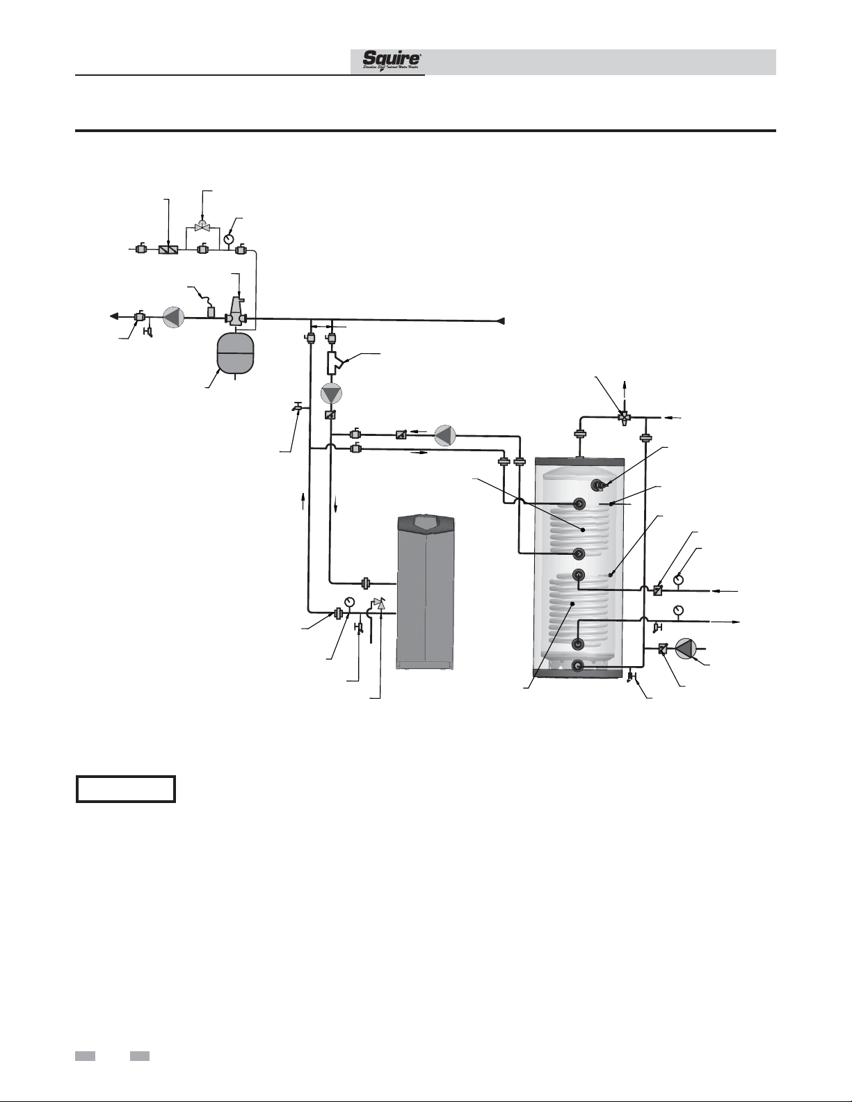
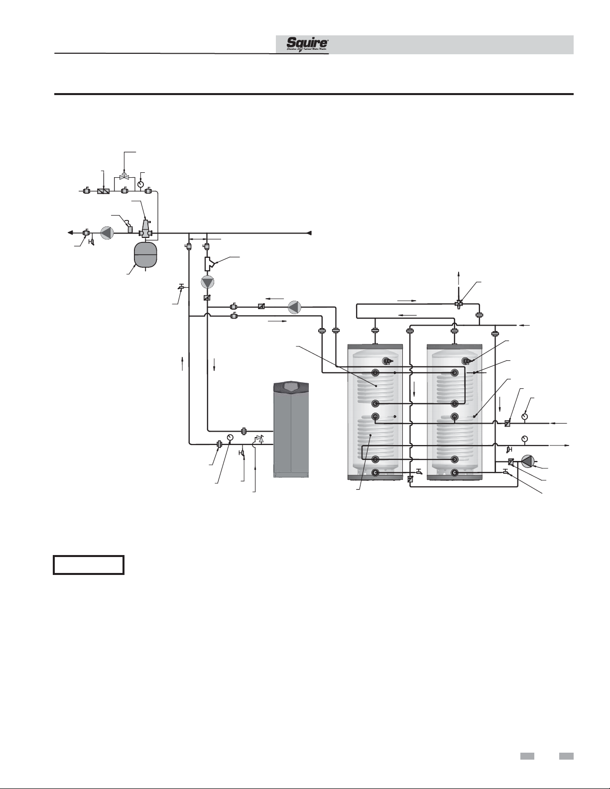
Figures 3-1 thru 3-4 show typical boiler side piping for
several common situations. Regardless of which system is
used it is imperative that the flow rates called for in Table
3C are developed through the coil. This requires properly
sized piping and a properly sized pump.
The systems shown in FIG’s 3-1 thru 3-4 are described
below:
Zone with Circulator to Aquastat
This system is like the circulator zone system on a straight
heat job except that one of the zones goes to the tank
instead of radiation. As on any circulator zone system
check valves should be installed in each zone to prevent
unwanted circulation through zones which are not calling
for heat. Figure 3-1 on page 8 illustrates typical circulator
zone piping.
Zone with Valve to Aquastat
As with the circulator zone system, this system is just like a
standard heating zone system except that one of the zones is
connected to the tank coil as shown in FIG. 3-2 on page 9.
The system circulator must be large enough to move boiler
water through the coil regardless of the flow rate required
through the heating zones.
Multiple Tank Connections (Boiler Side)
Multiple tank installations must be done in the “reverse-return”
manner. The reason for this is to create the same pressure drop
(and therefore, the same flow) through the coil of each tank.
The boiler manifold piping must be sized so that each coil has
the flow rate called for in Table 3B.
Because the pressure drop through tank coils varies from size
to size, it is hard to predict the flow rate that will be developed
through each coil when two tanks of different sizes are placed in
the same manifold. For this reason it is best not to mix tanks of
different sizes in the same zone if their recovery is critical.
DHW Prioritization
This piping system is designed to provide direct hot water
priority over the other zones in the heating system. When
there is a Domestic Hot Water (DHW) call for heat, the
Knight control will shut off the boiler circulator and
activate the domestic hot water circulator. Once the DHW
demand is satisfied, the boiler circulator will be readjusted
as demand requires. The circulator must be large enough
to move the boiler water through the coil in the tank,
and it must meet the minimum boiler flow requirments.
The recommended piping for a DHW priority system is
depicted in FIG. 3-3 on page 10.
6
Page 7

SDT/SET Installation & Operation Manual
3 Boiler Side Piping (SDT models) (continued)
Table 3A Pressure Drop Chart SDT/SET065-080
Table 3A
Pressure Drop Chart SDT/SET065-080
SDT / SET065 - 080 FRICTION LOSS
10.00
10.00
8.00
8.00
6.00
6.00
HDFT/
FT/HD
4.00
4.00
2.00
2.00
0.00
0.00
SDT / SET065 - 080 FRICTION LOSS
5 8 12 16 20
GPM
Table 3C Pressure Drop Values SDT/SET065-119
SOLAR
SOLAR
COIL
BOILER
BOILER
Table 3B Pressure Drop Chart SDT/SET119
Table 3B
Pressure Drop Chart SDT/SET119
COIL
COIL
COIL
FT/HD
12.00
10.00
8.00
6.00
4.00
2.00
0
5 8 12 16 20
GPM
SDT / SET119 FRICTION
LOSS
SOLAR
COIL
BOILER
COIL
MODEL
SDT065
SDT080
SDT119
SET065
SET080
SET119
Table 3C
Pressure Drop Values
PRESSURE DROP
COIL
CONN.
(IN)
COIL
LENGTH
(FT)
SQ FT
SURFACE
AREA
5
GPM8 GPM
SOLAR COIL
(FT / HD)
12
GPM16GPM20GPM
COIL
LENGTH
(FT)
SQ FT
SURFACE
AREA
5
GPM8 GPM
1 41.5 13.5 0.61 1.57 3.53 6.27 9.8 28 9.2 0.4 1.03 2.31 4.1 6.41
1 41.5 13.5 0.61 1.57 3.53 6.27 9.8 28 9.2 0.4 1.03 2.31 4.1 6.41
1 67.3 22.0 .73 1.87 4.22 7.5 11.71 48.5 16 0.61 1.57 3.53 6.27 9.8
1 41.5 13.5 0.61 1.57 3.53 6.27 9.8
1 41.5 13.5 0.61 1.57 3.53 6.27 9.8
1 67.3 22.0 .73 1.87 4.22 7.5 11.71
PRESSURE DROP
BOILER COIL
(FT / HD)
12
GPM16GPM20GPM
7
Page 8

SDT/SET Installation & Operation Manual
3 Boiler Side Piping (SDT models)
Figure 3-1 Piping Diagram Zoned with Circulators
ZONE #1
MAKE UP
WATER
DRAIN POINT
(TYPICAL)
BALL VALVE
(TYPICAL)
PRESSURE
REDUCING VALVE
BACKFLOW
PREVENTER
AIR SEPARATOR
EXPANSION
TANK
UNION
(TYPICAL)
TEMPERATURE /
PRESSURE
GAUGE
DRAIN
PRESSURE
RELIEF VALVE
GAS SUPPLY
PRESSURE
GAUGE
SYSTEM SUPPLY
SENSOR
(WHEN USED)
NOT TO EXCEED 4 PIPE DIA.
OR A MAXIMUM OF 12" APART
Y-STRAINER
FLOW CHECK
BOILER
CIRCULATOR
VALVE
BOILER BACKUP
HEAT EXCHANGER
( SDT MODELS ONLY )
SOLUTION
BOILER
SOLAR
HEAT EXCHANGER
ZONE#2ZONE
#3
HOT
WATER
OUT
SQUIRE
ZONE
#4
ZONE CIRCULATORS
(TYPICAL)
ANTI-SCALD
MIXING VALVE
COLD
WATER
IN
TEMPERATURE/
PRESSURE
RELIEF VALVE
BOILER
TANK SENSOR /
AQUASTAT
SOLAR SENSOR
CHECK VALVE
TEMPERATURE/
PRESSURE GAUGE
(TYPICAL)
RECIRCULATION
CHECK VALVE
DRAIN
( FIELD SUPPLY )
AUXILIARY CATCH PAN
FROM
SOLAR
TO
SOLAR
PUMP
NOTICE
NOTICE
8
Please note that these illustrations are meant to show system piping concept only, the installer is responsible
for all equipment and detailing required by local codes.
Please note that the installer is responsible for ensuring DHW prioritization when piped as a zone.
Page 9

SDT/SET
Installation & Operation Manual
3 Boiler Side Piping (SDT models) (continued)
Figure 3-2 Piping Diagram Zoned with Valves
ZONE #1
REDUCING VALVE
BACKFLOW
PREVENTER
MAKE UP
WATER
DRAIN POINT
(TYPICAL)
BALL VALVE
(TYPICAL)
PRESSURE
SYSTEM SUPPLY
SENSOR
(WHEN USED)
AIR SEPARATOR
EXPANSION
TANK
UNION
(TYPICAL)
TEMPERATURE /
PRESSURE
GAUGE
DRAIN
PRESSURE
RELIEF VALVE
GAS SUPPLY
PRESSURE
GAUGE
SYSTEM
CIRCULATOR
NOT TO EXCEED 4 PIPE DIA.
OR A MAXIMUM OF 12" APART
Y-STRAINER
BOILER
CIRCULATOR
BOILER BACKUP
HEAT EXCHANGER
( SDT MODELS ONLY )
SOLUTION
BOILER
SOLAR HEAT
EXCHANGER
ZONE
#2
SQUIRE
ZONE
#3
HOT
WATER
OUT
ZONE
#4
ZONE VALVES
(TYPICAL)
DIFFERENTIAL
PRESSURE
VALVE (IF USED)
ANTI-SCALD
MIXING VALVE
COLD
WATER
IN
TEMPERATURE/
PRESSURE
RELIEF VALVE
BOILER
TANK SENSOR /
AQUASTAT
SOLAR SENSOR
CHECK VALVE
TEMPERATURE/
PRESSURE GAUGE
(TYPICAL)
RECIRCULATION
CHECK VALVE
DRAIN
( FIELD SUPPLY )
AUXILIARY CATCH PAN
BYPASS
FROM
SOLAR
TO
SOLAR
PUMP
NOTICE
NOTICE
Please note that these illustrations are meant to show system piping concept only, the installer is responsible
for all equipment and detailing required by local codes.
Please note that the installer is responsible for ensuring DHW prioritization when piped as a zone.
9
Page 10
SDT/SET Installation & Operation Manual
3 Boiler Side Piping (SDT models)
Figure 3-3 Knight Boiler Primary / Secondary Piping
TO
S
YSTEM
BALL VALVE
(TYPICAL)
BACKFLOW
PREVENTER
MAKE UP WATER
SEPARATOR
CIRCULATOR
EXPANSION
PRESSURE
REDUCING VALVE
SYSTEM SUPPLY
SENSOR
AIR
SYSTEM
TAN K
PRESSURE
GAUGE
DRAIN POINT
(TYPICAL)
NOT TO EXCEED 4 PIPE DIA. OR
A MAXIMUM OF 12" APART
Y-STRAINER
(RECOMMENDED)
BOILER
CIRCULATOR
DOMESTIC
HOT WATER
CIRCULATOR
BOILER BACKUP
HEAT EXCHANGER
(SDT MODELS ONLY)
FROM
SYSTEM
ANTI-SCALD
MIXING VALVE
HOT
WATE R
OUT
COLD
WATE R
IN
TEMPERATURE/
PRESSURE RELIEF VALVE
BOILER
TANK SENSOR /
AQUASTAT
SOLAR SENSOR
CHECK VALVE
TEMPERATURE/
PRESSURE GAUGE
(TYPICAL)
FROM SOLAR
NOTICE
UNION
(TYPICAL)
TEMPERATURE /
PRESSURE
GAUGE
DRAIN
PRESSURE
RELIEF VALVE
KNIGHT
BOILER
SOLAR
HEAT EXCHANGER
SQUIRE
CHECK VALVE
DRAIN
(FIELD SUPPLY)
TO SOLAR
RECIRCULATION
PUMP
Please note that these illustrations are meant to show system piping concept only, the installer is responsible
for all equipment and detailing required by local codes.
10
Page 11
SDT/SET Installation & Operation Manual
3 Boiler Side Piping (SDT models) (continued)
Figure 3-4 Multiple Tank Connections
PRESSURE
REDUCING VALVE
BACKFLOW
PREVENTER
MAKE UP
WATER
TO
SYSTEM
BALL VALVE
(TYPICAL)
AIR SEPARATOR
SYSTEM
SUPPLY SENSOR
SYSTEM
CIRCULATOR
SYSTEN
CIRCULATOR
EXPANSION
TAN K
PRESSURE
GAUGE
DRAIN POINT
(TYPICAL)
UNION
(TYPICAL)
TEMPERATURE/
PRESSURE GAUGE
NOT TO EXCEED 4 PIPE DIA. OR
A MAXIMUM OF 12” APART
Y-STRAINER
(RECOMMENDED)
BOILER
CIRCULATOR
DRAIN
PRESSURE
RELIEF VALVE
DOMESTIC
HOT WATER
CIRCULATOR
KNIGHT
BOILER
FROM SYSTEM
SOLAR
HEAT
EXCHANGER
(TYPICAL)
SQUIRE
HOT
WATER
OUT
SQUIRE
ANTI-SCALD
MIXING VALVE
TEMPERATURE/
PRESSURE
RELIEF VALVE
BOILER
TANK SENSOR/
AQUASTAT
SOLAR SENSOR
COLD WATER IN
CHECK VALVE
TEMPERATURE/
PRESSURE GAUGE
(TYPICAL)
RECIRCULATION
PUMP
CHECK VALVE
(TYPICAL)
DRAIN
(FILED SUPPLIED)
FROM
SOLAR
TO
SOLAR
NOTICE
Please note that these illustrations are meant to show system piping concept only, the installer is responsible for
all equipment and detailing required by local codes.
11
Page 12
4 Domestic Side (Tank) Piping
SDT/SET Installation & Operation Manual
Basic Domestic Piping
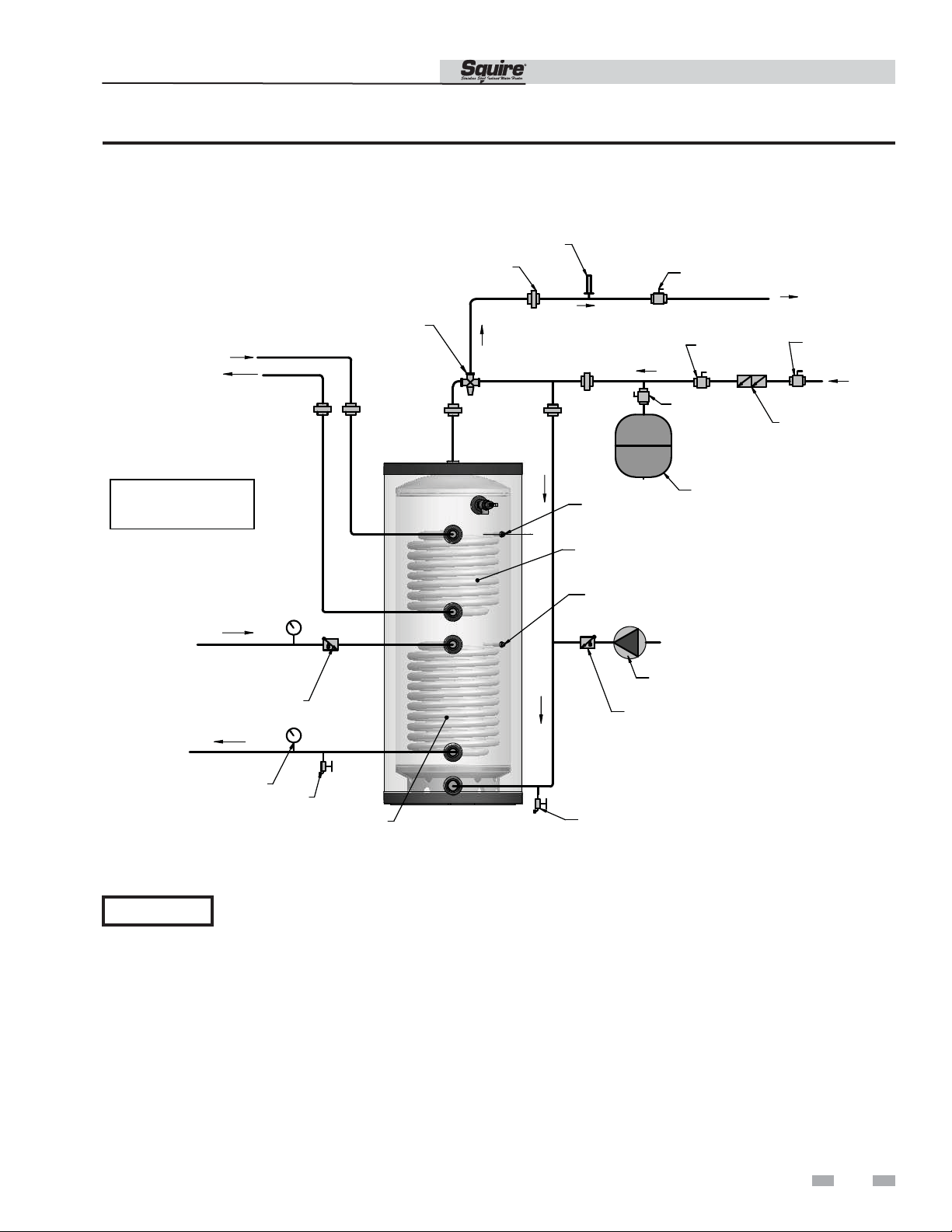
Figure 4-2 on page 15 shows typical domestic water piping
for a tank. The function of the components shown are as
follows:
a. Shut-off valves (recommended) - Used to isolate the
tank for servicing.
b. Backflow Preventer (required by some codes) - Used to
prevent water from backing out of the tank and into
the main potable water supply in the event that inlet
water pressure drops.
c. Expansion Tank (required for thermal expansion) Absorbs the increased volume caused by heating water.
Use an expansion tank designed for use on
domestic water systems. Refer to the expansion tank
manufacturer’s literature for the proper size expansion
tank to use.
NOTICE
d. Unions (recommended) - Used to disconnect the tank
in the unlikely event that this is necessary.
When an expansion tank is used, do not
put any valves between the expansion
tank and tank inlet.
Domestic Water Piping for Distant Fixtures
In some cases the furthest fixture may be quite distant from the
tank. Such an installation would result in an unacceptable delay
before hot water reaches these distant fixtures. Even if all the
fixtures are relatively close to the tank, the building owner may
want hot water at all fixtures as soon as they are opened.
To prevent delays, return circulation piping with a check valve
that allows flow to the inlet of the tank. This should be installed
on each branch circuit at the farthest fixture or device, so that
hot water is supplied upon demand.
Because hot water is always circulating in the hot water branch,
the entire branch should be insulated to prevent excessive heat
loss.
e. Drain (required) - Used to drain the tank for inspection
or servicing.
Multiple Tank Domestic Water Piping
The two pipe reverse return piping uses more pipe than the
two pipe direct return piping, but the flow is more balanced
and even in the two pipe reverse return piping layout
(see FIG. 3-4).
Each tank must have its own T&P valve. It is recommended
that each tank be equipped with its own isolation valves,
unions, and drains so that one tank may be removed from
the system. If local codes require a backflow preventer,
check with the appropriate authority to find out whether
one backflow preventer may be used for tanks or each tank
must be equipped with its own backflow preventer. If each
tank must have its own backflow preventer, each tank must
also have its own expansion tank. If a common backflow
preventer is permitted, an expansion tank must be sized to
accommodate the expansion volume of all tanks.
12
Page 13
SDT/SET Installation & Operation Manual
4 Domestic Side (Tank) Piping (continued)
Anti-scald Valves (Mixing Valves)
Anti-scald valves used with water heaters are also called
tempering valves or mixing valves. An anti-scald valve
mixes cold water in with the outgoing hot water to assure
that hot water reaching a building fixture is at a temperature
low enough to be safe. ASSE1017 and ASSE1070 certified
valves are recommended.
Usually, the maximum temperature of the outlet water
will stay near the setting of the tank control. In some cases,
however, hot water usage patterns can cause the outlet
water temperature to rise significantly above the control
setting.
The temperature of water going to the fixtures may be
more carefully controlled through the use of a thermostatic
mixing valve. This device blends a controlled amount of
cold water with the hot water leaving the tank so that water
at a more constant temperature exits the mixing valve.
Anti-scald mixing valve piping is illustrated in FIG.’s 3-1
thru 3-4.
WARNING
An anti-scald mixing valve does not
eliminate the risk of scalding.
• Set the tank thermostat as low as
practical.
• Feel water before bathing or
showering.
• If anti-scald or anti-chill protection
is required, use devices specifically
designed for such service. Install
these devices in accordance with
their manufacturer’s instructions.
Temperature & Pressure (T&P) Relief Valve
WARNING
For protection against excessive temperatures
and pressure, install temperature and
pressure protective equipment required by
local codes, but not less than a combination
temperature and pressure relief valve certified
by a nationally recognized testing laboratory
that maintains periodic inspection of
production of listed equipment or materials
as meeting the requirements for Relief Valves
and Automatic Gas Shutoff Devices for Hot
Water Supply Systems, ANSI Z21.22 and the
Standard CAN1-4.4, Temperature, Pressure,
Temperature and Pressure Relief Valves and
Vacuum Relief Valves. The combination
temperature and pressure relief valve shall
be marked with a maximum set pressure not
to exceed the maximum working pressure
of the water heater. The combination
temperature and pressure relief valve shall
also have an hourly rated temperature steam
BTU discharge capacity not less than shown
in Table 4A, page 14.
Install the combination temperature and
pressure relief valve into the opening
provided and marked for this purpose on
the water heater.
Install Drain Valve
Drain valve and fittings are supplied by others.
Standard Installation
• Install a tee connection at the domestic cold water
inlet (FIG. 4-1).
Figure 4-1 Drain Valve Installed
DRAIN
VALV E
13
Page 14
4 Domestic Side (Tank) Piping
SDT/SET Installation & Operation Manual
NOTICE
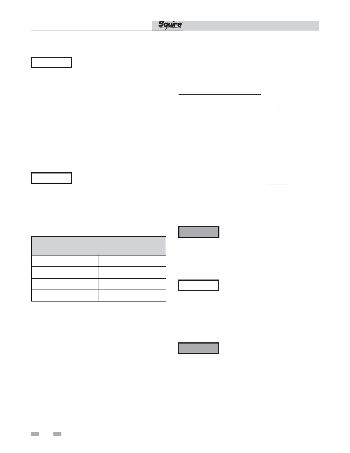
Do not place a valve between the combination temperature
and pressure relief valve and the tank.
Determine T&P relief valve size by the following
specifications, unless they conflict with local codes:
- SDT/SET065/080/119 - 3/4" NPT with a
minimum CSA Rating of 200,000 Btu/hr.
NOTICE
Verify that the combination
temperature and pressure relief valve
complies with local codes. If the
combination temperature and pressure
relief valve does not comply with local
codes, replace it with one that does.
Follow the installation instructions in
this section.
The Lochinvar SDT/SET series water
heaters will absorb/store less than 200,000
Btu/hr when domestic water outlet
temperature is 210°F and boiler water
supply temperature is 240°F. Listed
outputs are based on ASME Section VIII
Interpretation VIII-1-86-136. Check
with local codes for applicability.
Table 4A
Minimum Relief Valve (CSA Rating)
Model BTU/hr
SDT/SET065 200,000
SDT/SET080 200,000
SDT/SET119 200,000
Standard Installation
• Install the T&P relief valve in the connection marked
“Relief Valve”.
T&P Relief Valve Discharge Piping
T&P relief valve discharge piping must be:
- made of material serviceable for a temperature of
250°F or greater.
- directed so that hot water flows away from all
persons.
- directed to a suitable place for disposal.
- installed so as to allow complete draining of the T&P
relief valve and discharge line.
- terminated within 6" of the floor.
T&P relief valve discharge piping must not be:
- excessively long. Using more than two (2) elbows or
15 feet of piping can reduce discharge capacity.
- directly connected to a drain. Refer to local codes.
- subject to freezing.
WARNING
CAUTION
Do not install any valve between the T&P
relief valve and the tank connection or
on the T&P relief valve discharge piping.
Improper placement and piping of T&P
relief valve can cause severe personal
injury, death or substantial property
damage.
The T&P relief valve is not intended
for constant duty, such as relief of
pressure due to repeated normal system
expansion. Correct this condition by
installing a properly sized expansion
tank in a domestic water system. Refer
to the expansion tank manufacturer’s
installation instructions for proper sizing.
14
WARNING
Failure to install and maintain a new, listed
3/4" X 3/4" temperature and pressure
relief valve will release the manufacturer
from any claim which might result from
excessive temperature and pressures.
Page 15
SDT/SET
4 Domestic Side (Tank) Piping (continued)
Figure 4-2 Recommended Domestic Water Piping SDT/SET models
SHOCK ARRESTOR
UNION
(TYPICAL)
ANTI-SCALD
MIXING VALVE
FROM BOILER
TO BOILER
(SDT MODELS ONLY)
Installation & Operation Manual
SHUTOFF VALVE
SHUTOFF
VALVE
SHUTOFF
VALVE
SHUTOFF
VALVE
BACKFLOW
PREVENTOR
NOTE: UPPER COIL
REPLACED WITH ELEMENT
ON SET MODELS
FROM SOLAR
CHECK VALVE
TO SOLAR
TEMPERATURE /
PRESSURE
GAUGE
(TYPICAL)
NOTICE
Please note that these illustrations are meant to show system piping concept only, the installer is responsible
for all equipment and detailing required by local codes.
DRAIN
SOLAR
HEAT EXCHANGER
SQUIRE
BOILER
TANK SENSOR/
AQUASTAT
BOILER BACKUP
HEAT EXCHANGER
( SDT MODELS ONLY )
SOLAR SENSOR
RECIRCULATION
PUMP
CHECK VALVE
DRAIN
( FIELD SUPPLY)
EXPANSION
TANK
15
Page 16
T
SDT/SET Installation & Operation Manual
5 Wiring
Electrical Connection
(Squire solar water heater with electric back up only -- SET models only)
WARNING
CAUTION
The 4500-watt heating element in the Squire SET is wired
to the junction box on top of the heater and it requires
240-volt/ A.C. electrical service. The voltage requirement
and wattage load for the heater is also specified on the
heater identification plate. A 1/2" E.M.T. opening, located
on top of the unit is provided for a field wiring connection.
Consult an electrician to determine if your electrical service
is adequate for the additional load of the heater. The
electrical installation should be done by a qualified licensed
electrician. All wiring must conform to the National
Electric Code and local codes.
CAUTION
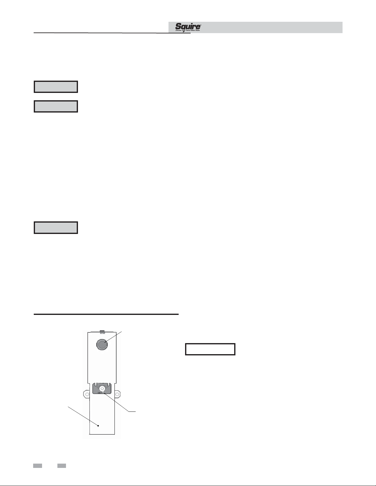
Figure 5-1 Thermostat
Tank must be full before the unit is turned on! The heating element will be damaged if energized for even
a short period of time while tank is dry!
Be sure to ground the water heater. The preferred way to ground is to use rigid metal conduit between
the main panel and the water heater junction box with approved end fittings. The separate ground wire
connection provided in the water heater junction box must also be grounded. Replace the junction box
cover and insulation after you have made all wiring connections.
The manufacturer’s warranty does not
cover any damage or defect caused by
the installation, attachment or use of
any type of unapproved devices into,
onto or in conjunction with this water
heater. The use of unauthorized energy
saving devices may shorten the life of
the water heater and may endanger
life and property. The manufacturer
disclaims any responsibility for such
loss or injury resulting from the use of
such unauthorized devices.
RESET BUTTON
After the water and electrical connections have been made and
the tank has been fi lled with water, turn on the power to the
heater. The heater is now operational.
Thermostat Adjustment
The thermostat is located in the front of the heater. The access
cover must be removed to adjust to the factory default setting of
120°F. This temperature is satisfactory for the average household
use.
1. Turn OFF power to the heater.
2. Remove access cover and insulation. Do NOT remove the
thermostat protective cover.
3. Set the temperature indicator to desired temperature.
Replace insulation access cover.
4. Turn ON power to heater.
Combination “Thermostat and High Limit
Control (ECO)”
This heater is equipped with a combination thermostat and high
limit safety. If for any reason the water temperature becomes
eccessively high, the “High Limit Control (ECO)” breaks the
circuit to the heating element. Once the switch opens, it must
be reset manually.
NOTICE
To reset, press the red button as shown in FIG. 5-1. Replace
the insulation and access cover before turning on power to the
heater.
HERMOSTAT
PROTECTIVE
COVER
THERMOSTAT
DIAL POINTER
The cause of the over temperature
condition must be corrected first.
16
Page 17
5 Wiring (continued)
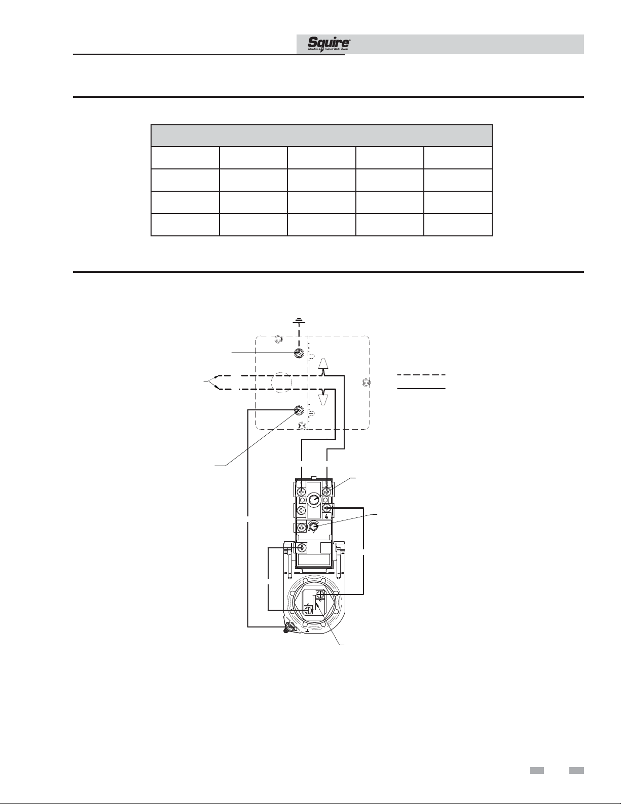
Table 5A Wiring SET065-SET119
SDT/SET Installation & Operation Manual
SET Wiring
(Single Element)
Model Volts / Phase Watts / AMPS Breaker Type *Wire Gage
SET065
SET080
SET119
Rated for 90°C
*
240 VAC / 1 Ph 4500 / 18.3 25 AMP / DPDT 12 ga. THHW
240 VAC / 1 Ph 4500 / 18.3 25 AMP / DPDT 12 ga. THHW
240 VAC / 1 Ph 4500 / 18.3 25 AMP / DPDT 12 ga. THHW
Figure 5-2 Combination Thermostat and High Limit Control, SET 065-SET119
SERVICE
GROUND SCREW
LINE
VOLTAGE
RD
BK
FIELD
SUPPLIED
FACTORY
INSTALLED
GROUND
SCREW
RD
BK
HIGH LIMIT
GR
BK
ELEMENT
THERMOSTAT
RD
17
Page 18
SDT/SET Installation & Operation Manual
5 Wiring
Indirect Water Heater Sensor Setup (Knight Boiler)
CAUTION
NOTICE
Label all wires prior to disconnection when servicing controls. Wiring errors can cause improper and
dangerous operation.
The supplied sensor contains an Auto Reset High Limit (194°F).
Install tank sensor
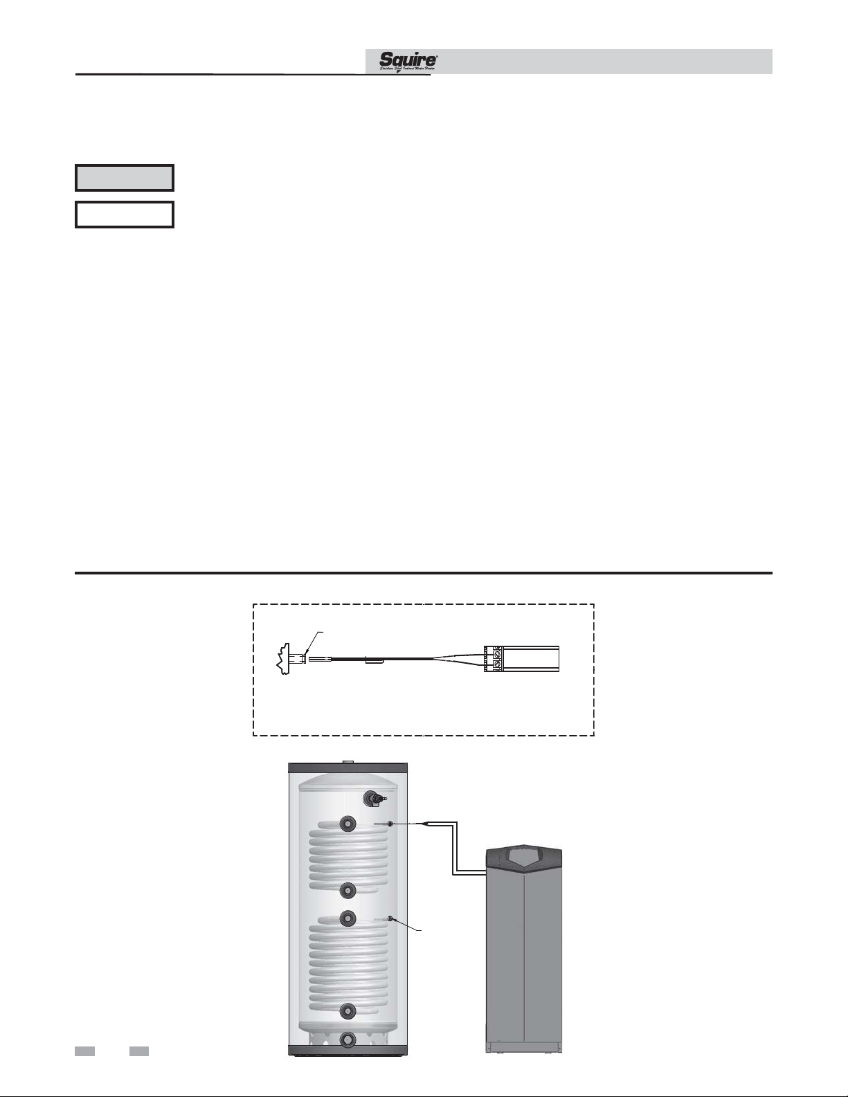
The tank sensor is a dual sensor which controls the
temperature of the tank from the boiler(see FIG. 5-3). The
tank sensor has a built-in high temperature limit set at
194°F.
1. Install the tank sensor inside the tank as depicted in
FIG. 5-3.
2. Connect the wire leads to the DHW tank sensor (AUX)
connection point on the Knight boiler connection
board (see FIG. 5-3).
3. The Knight boiler will automatically read the sensor
and default the tank temperature settings to 125°F.
4. Adjust the tank set point program. Reference the Knight
Installation and Operation manual for a detailed
explanation of the tank set point program.
Connect tank sensor
1. Turn OFF the power to the unit. Use wire strippers to strip
one inch of insulation from the ends of each wire that will
be spliced.
2. Splice the two ends of bare wire by twisting them together
with a pair of electrical pliers. Turn the pliers three or four
times to make a suffi cient connection.
3. Attach a wire nut at the point where the two wires have
been twisted together. Twist the wire nut until it fi ts snugly
or until it can no longer be twisted.
4. Wrap the wire nut and the two wires with electrical tape
to secure the connection. Cover any exposed wiring with
electrical tape.
Figure 5-3 Indirect Water Heater Controlled Using Tank Sensor
TANK BULBWELL
DHW TANK SENSOR / AUTO RESET HIGH LIMIT
(PLACE SENSOR IN TANK BULBWELL & SNAP
CLIP OVER BULBWELL)
SOLAR SENSOR
(FIELD SUPPLIED)
DHW TANK
SENSOR
KNIGHT LOW VOLTAGE
TERMINAL STRIP
18
INDIRECT TANK
KNIGHT BOILER
Page 19
SDT/SET Installation & Operation Manual
5 Wiring (continued)
Indirect Water Heater Controlled Using Aquastat and Zone Circulator / Valve
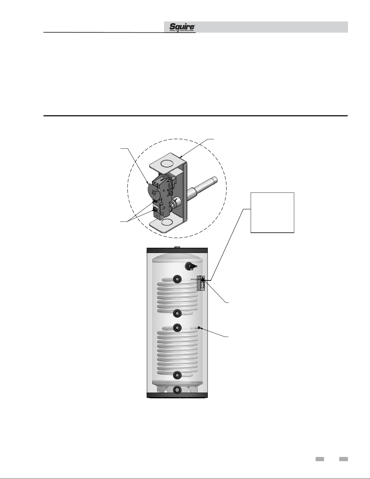
1. Install Aquastat to tank. Aquastat control (TST20016) can be ordered from your local Lochinvar distributor.
2. Connect Aquastat to the zone controller for the Indirect Water Heater Zone.
3. Adjust Aquastat to the desired temperature.
Figure 5-4 Wiring for Zone Control
TST20016
TEMPERATURE
ADJUSTMENT
ZONE CONTROL BOX
OR
ZONE VALVE
WIRE
CONNECTIONS
OR
ZONE CIRCULATOR
INDIRECT TANK
BOILER
AQUASTAT
CONTROL
SOLAR SENSOR
(FIELD SUPPLIED)
19
Page 20

6 Start-up and Check-out
1. Make sure the system is free of leaks and that air is
purged from the system.
SDT/SET Installation & Operation Manual
CAUTION
2. Many soldering fluxes contain Zinc Chloride which
can cause severe corrosion damage to stainless steel. After
completing all domestic water connections, flush the
indirect water heater thoroughly before leaving the
installation. This is particularly important if the indirect
water heater will be unused for an extended period of time
after installation. Flush the indirect water heater by
drawing at least three times its volume from the tank.
3. Make sure that all electrical connections are made correctly
and that no high voltage wiring is exposed.
4. Make sure that each zone valve or circulator operates only
when its thermostat calls for heat. Let each zone operate
long enough to purge any remaining air from the system.
5. Set the indirect water heater to the desired temperature.
Because hot water presents a scald hazard, it is best to set
the thermostat at 120°F or lower and raise it only if
necessary to provide adequate hot water.
Fix any leaks found before proceeding
further. Leakage from the boiler piping
can result in severe damage to the boiler.
6. Re-enable the burner and allow the boiler to operate.
Make sure that the boiler shuts down when the indirect
water heater is satisfied.
20
Page 21

7 Maintenance
The Lochinvar SDT/SET series indirect water heater is an
extremely simple device and it requires very little maintenance.
There are, however, several items which should be inspected
on an annual or as needed basis to ensure a reliable supply of
hot water:
Make sure that the rest of the solar, boiler and domestic water
piping is free of leaks.
• If there is an oil lubricated circulator in the system,
make sure it is lubricated as called for by the circulator
manufacturer.
• Make sure that the boiler is maintained in accordance
with the boiler manufacturer’s instructions.
• If a water treatment system is required to keep the water
chemistry within the parameters shown in Table 2A
(see Section 2 - Pre-Installation), make sure that this
system is properly maintained.
Maintenance Schedule
Annual service by a qualified service technician
should include the following:
Any procedure required by local codes.
Verify system pressure. Air venting procedure may
require adding water to bring boiler system up to
pressure, typically 12 psig.
Manually operate T&P relief valve at least once a year.
This will release some hot water.
WARNING
Move operating lever to open position for a few
seconds and then move it back, allowing it to snap
closed. After the T&P relief valve is operated, if it
continues to release water, close the cold water inlet to
the water heater immediately. Follow the draining
instructions, and replace the T&P relief valve. If the
T&P relief valve weeps periodically, it may be due to
thermal expansion. Do not plug the T&P relief valve or
discharge piping.
DANGER
Follow instructions on circulator to oil, if required.
Check mixing valve, valves, pipes, and fittings for leaks.
Check function of the field-installed controls and valves.
See component manufacturer’s instructions.
Review homeowner’s maintenance responsibilities and
their frequencies, including any not listed in the
following section.
Before operating a T&P relief valve, make
sure no one is in front of or around the
T&P relief valve discharge piping. Hot
discharge water can cause severe personal
injury or substantial property damage.
Plugging the T&P relief valve or discharge
piping can cause excessive pressure in the
water heater, resulting in severe personal
injury, death, or substantial property
damage.
SDT/SET Installation & Operation Manual
Homeowner monthly maintenance to include:
Visually check valves, pipes, and fittings for leaks. Call a
qualified service technician to repair leaks.
To Fill the Water Heater
1. Close the water heater drain valve by turning the knob
clockwise.
2. Open the cold water supply shutoff valve.
3. Open several hot water faucets to allow air to escape from
the system.
4. When a steady stream of water flows from the faucets, the
water heater is filled. Close the faucets and check for water
leaks at the water heater drain valve, combination
temperature and pressure relief valve and the hot and cold
water connections.
WARNING
To Drain the Water Heater
Should it become necessary to completely drain the water heater,
be sure to follow the steps below:
1. Disconnect the power supply from the heat source. Consult
a plumbing professional or the electric company in your
area for service.
2. Close the cold water supply shutoff valve.
3. Open the drain valve on the water heater.
4. Open a hot water faucet to allow air to enter the system.
Drain the water heater if it will be shut off and exposed to
freezing temperatures. Freezing water will expand and damage
the water heater.
• If boiler water contains sufficient antifreeze, then
only the domestic water needs to be drained.
Water from opened drain valves, unions and
other connections may be extremely hot.
To avoid severe personal injury, death, or
substantial property damage:
- Tighten all drain hose connections.
- Direct hot water away from all
persons.
• If boiler water does not contain sufficient antifreeze,
the boiler water and the domestic water must be
drained.
If antifreeze is used in the boiler water, check concentration.
Boiler water (including additives) must be practically non-toxic,
having a toxicity rating or class of 1, as listed in the Clinical
Toxicology of Commercial Products. A maximum 50/50 mixture
of inhibited propylene glycol is recommended. Follow the
antifreeze manufacturer’s instructions.
WARNING
Do not use automotive, ethylene glycol
or petroleum-based antifreeze. Do not use
any undiluted antifreeze. This can cause
severe personal injury, death, or substantial
property damage.
21
Page 22
8 Performance Data
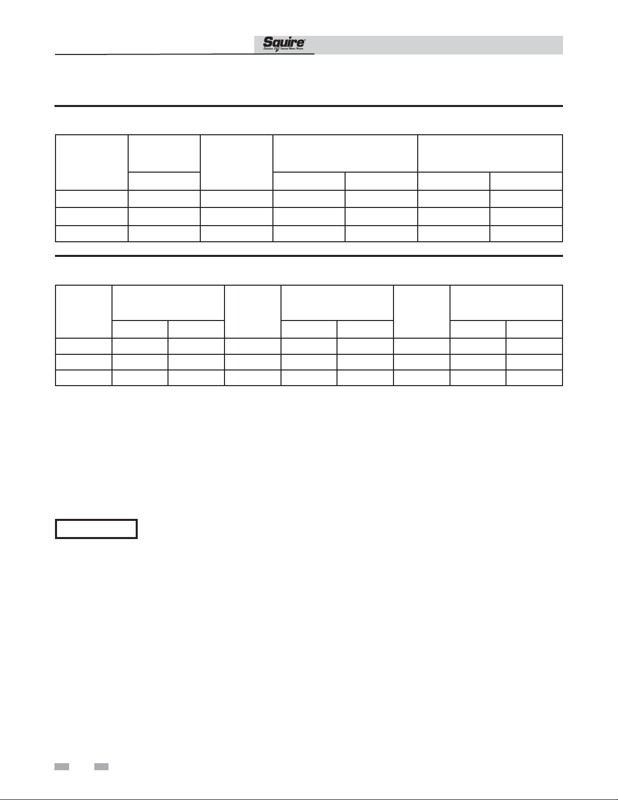
Table 8A SET Backup Recovery Performance
SDT/SET Installation & Operation Manual
Heat Exchanger
Volume
Model
SET065 2.2 28 78 108 34 26
SET080 2.2 35 89 123 44 31
SET119 3.2 44 120 166 55 42
Gallons
Solar
Heated
Water
Volume
Gallons
65°F
Rise
Recovery
Back Up
Minutes
90°F
Rise
* First Draw
Gallons
115°F 140°F
Table 8B SDT Backup Recovery Performance
Heat Exchanger
Volume
Model
SDT065 1.9 2.2 32 8 13
SDT080 1.9 2.2 36 9 15
SDT119 2.6 3.2 53 10 17
Gallons
Boiler Solar 65°F Rise 90°F Rise 115°F 140°F
Heated
Water
Volume
Gallons
Recovery
Back Up
Minutes
Boiler
Output for
Recovery
BTU/HR
128,000
128,000
217,000
42 30
49 35
65 50
*Amount of water drawn from tank with no energy input
How to Properly Size Your Indirect Water Heater
* First Draw
Gallons
Use the First Hour Rating (FHR) to properly size your indirect water heater. The FHR is the amount of hot water (in gallons)
that the water heater can supply in the first hour of operation (starting with a tank full of hot water). The FHR is dependent
on tank capacity, source of heat, and the size of the burner.
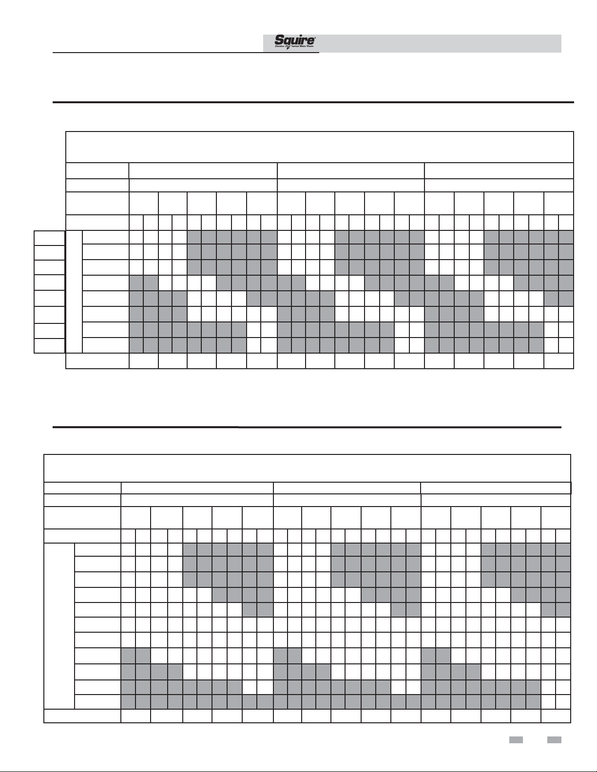
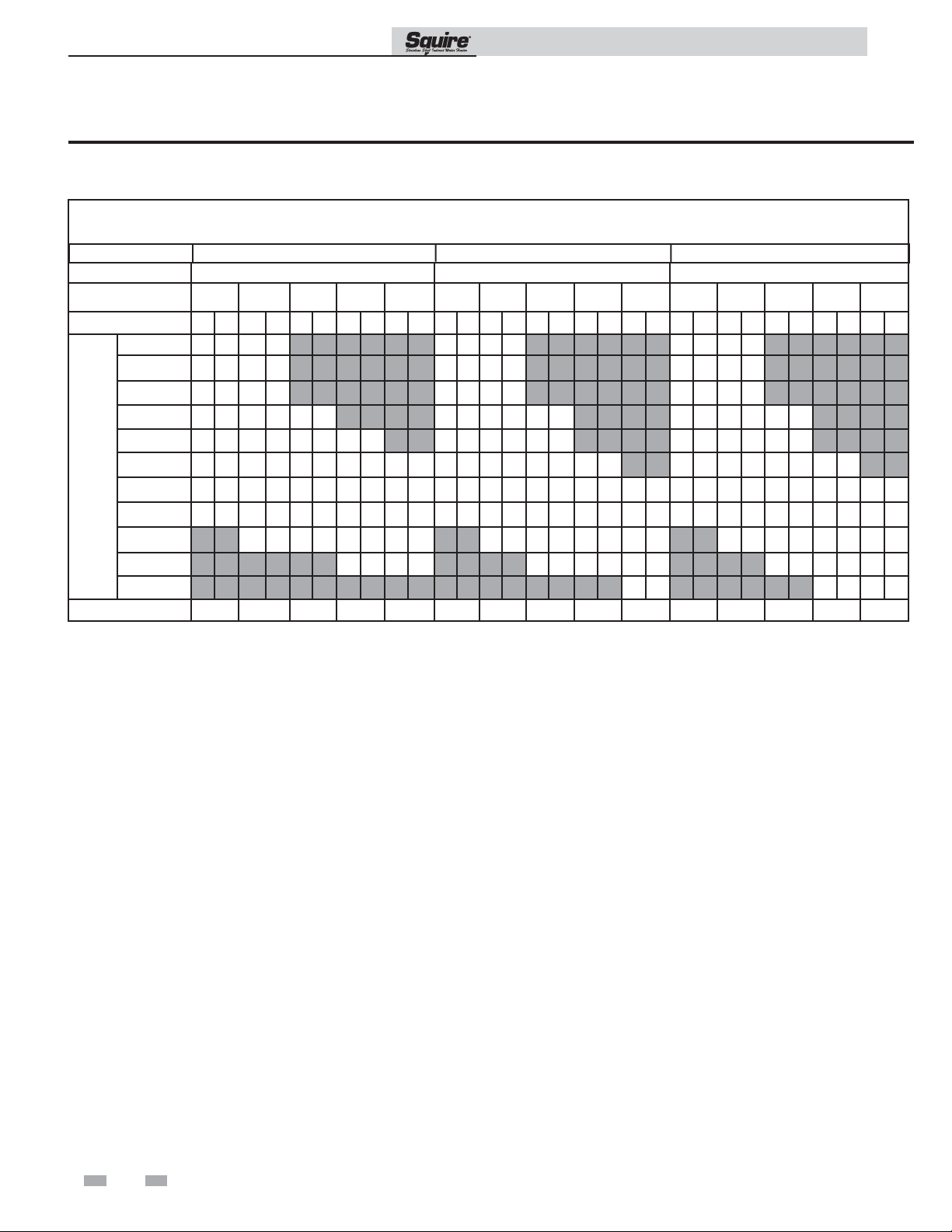
The indirect water heater and boiler sizing charts can be found on pages 23 and 24. Locate your indirect water heater and boiler
along with your required FHR. This will also determine the flow needed between the indirect water heater and boiler.
NOTICE
The charts utilize only the upper boiler
coil and the upper half of the tank.
22
Page 23
SDT/SET Installation & Operation Manual
8 Performance Data (continued)
Table 8C First Hour Rating - 180°F Boiler Loop Water (Knight and Wall Mount Boilers, Upper Coil SDT Models)
First Hour Rating - 180°F Boiler Loop Water
(Knight Boiler - SDT065 - SDT119)
Model SDT065 SDT080 SDT119
WB050
K/WB081
K/WB106
K/WB151
K/WB211
KB286
KB400
KB501
Boiler Supply Water
Circulator Flow
GPM
Domestic Outlet 115 140 115 140 115 140 115 140 115 140 115 140 115 140 115 140 115 140 115 140 115 140 115 140 115 140 115 140 115 140
45,000 117 92 117 92 122 97 122 97 138 113 138 113
72,000 169 129 169 129 174 134 174 134 191 150 191 150
94,000 205 154 211 159 210 159 216 164 234 181 234 181
135,000 235 176 255 190 240 181 260 195 314 238 314 237
190,000 255 190 281 208 260 195 286 213 385 288 413 308
260,000 255 190 281 208 301 222 260 195 286 213 306 227 385 288 413 308 475 351
373,000 301 222 306 227 475 351
Boiler Heating Capacity
467,000 301 222 306 227 475 351
MAX BTU INPUT
5 8 12 16 20 5 8 12 16 20 5 8 12 16 20
90256 106525 116697 130105 139966 90257 106525 116698 130105 139967 123218 148780 171607 185675 217372
180 180 180
Note: Testing conducted with 50°F inlet cold water
Table 8D First Hour Rating - 180°F Boiler Loop Water (Universal Sizing. Upper Coil SDT Models)
First Hour Rating - 180°F Boiler Loop Water
(Universal Sizing - 45,000 - 295,000 Btu/hr / SDT065-SDT119)
Model SDT065 SDT080 SDT119
Boiler Supply Water
Circulator Flow
GPM
Domestic Outlet
45,000 117 92 117 91 122 97 122 97 138 113 138 113
60,000 146 112 146 112 151 117 151 117 168 134 168 134
75,000 174 133 174 133 180 138 180 138 197 154 197 154
95,000 205 154 213 160 213 160 210 159 218 165 218 165 236 182 236 182 236 182
115,000 205 154 235 175 254 189 254 189 210 159 240 180 254 190 254 190 275 210 275 210 275 210 275 210
140,000 205 154 235 175 260 193 286 211 295 218 210 159 240 180 260 195 286 213 306 227 292 222 324 244 324 244 324 244 324 244
165,000 205 154 235 175 260 193 286 211 295 218 210 159 240 180 260 195 286 213 306 227 292 222 341 257 373 279 373 279 373 279
195,000 235 175 260 193 286 211 295 218 240 180 260 195 286 213 306 227 341 257 385 288 413 308 431 320
225,000 260 193 286 211 295 218 260 195 286 213 306 227 385 288 413 308 475 351
260,000 295 218 306 227 475 351
Boiler Heating Capacity
295,000 475 351
MAX BTU INPUT
5 8 12 16 20 5 8 12 16 20 5 8 12 16 20
115 140 115 140 115 140 115 140 115 140 115 140 115 140 115 140 115 140 115 140 115 140 115 140 115 140 115 140 115 140
90256 106525 118352 131827 139966 90257 106525 118352 131827 139967 123218 148780 171607 185675 217372
180 180 180
Note: Testing conducted with 50°F inlet cold water
23
Page 24
SDT/SET Installation & Operation Manual
8 Performance Data
Table 8E First Hour Rating 200°F Boiler Loop Water (Universal Sizing, Upper Coil SDT Models)
First Hour Rating - 200°F Boiler Loop Water
(Universal Sizing - 45,000 - 295,000 Btu/hr / SDT065-119)
Model SDT065 SDT080 SDT119
Boiler Supply Water
Circulator Flow
GPM
Domestic Outlet
45,000 117 94 117 94 122 99 122 99 135 113 135 113
60,000 146 115 146 115 151 120 151 120 164 133 164 133
75,000 175 137 175 137 180 142 180 142 192 154 192 154
95,000 214 165 214 165 214 165 206 160 206 160 206 160 230 182 230 182 230 182
115,000 252 193 252 193 252 193 252 193 270 208 243 187 243 187 268 210 268 210 268 210
140,000 265 203 283 216 283 216 283 216 283 216 270 208 286 220 286 220 286 220 315 245 315 245 315 245 315 245
165,000 265 203 305 232 328 249 328 249 328 249 270 208 310 237 333 254 333 254 333 254 357 276 362 279 362 279 362 279 362 279
195,000 265 203 305 232 334 253 349 265 369 279 270 208 310 237 339 258 367 279 374 284 357 276 419 321 419 321 419 321 419 321
225,000 305 232 334 253 349 265 369 279 310 237 339 258 367 279 374 284 432
260,000 349 265 369 279 339 258 367 279 374 284 487 372 530 403 542 412
295,000 374 284 530 403 602 456
Boiler Heating Capacity
MAX BTU INPUT
5 8 12 16 20 5 8 12 16 20 5 8 12 16 20
115 140 115 140 115 140 115 140 115 140 115 140 115 140 115 140 115 140 115 140 115 140 115 140 115 140 115 140 115 140
121786 153207 168199 176783 188081 121786 153207 168199 176783 188081 162144 202222 231672 253492 291792
200 200 200
475 362 475 362 475 362
331
Note: Testing conducted with 50°F inlet cold water
24
Page 25
9 High Output Piping
SDT/SET Installation & Operation Manual
High Domestic Hot Water Usage
When a large amount of hot water is required by a Domestic
Hot Water system, the dual coil indirect water heater can be
piped together when given the high volume needed to satisfy
the high load demands. This is achieved by piping the boiler
coil and solar coil together. This will enable heat transfer to
both the heat exchangers at the same time. This is done by
series piping or piping in parallel. A decision must be made to
choose a particular system based on the heating coil pressure
drop and the desired flows. This type of piping can be done
in a solar operation as well as with a boiler to acheive this
maximum heat transfer into the water.
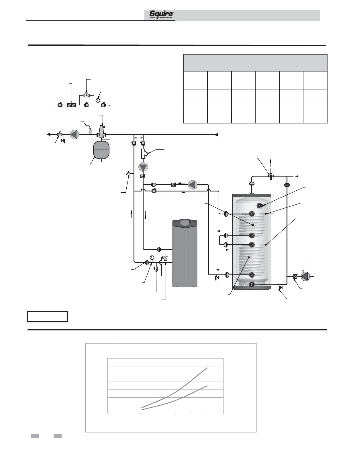
Series Piping
With this style of installation, the solar / boiler supply piping
is connected to boiler water IN connection. When joining
in this operation, all fittings must be no smaller than 1" in
size. Then, the boiler water OUT and the solar water IN are
connected. This will join the boiler and soiler coils together.
The return water is piped from the solar return to the
solar / boiler supply. See FIG. 9-1 on page 26.
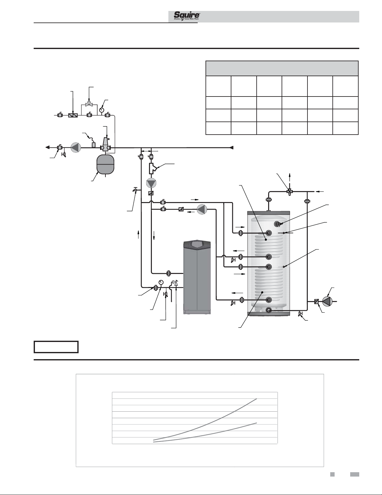
Parallel Piping
With this style of installation, both heat exchanger are used at
the same time. Solar / boiler supply piping to the solar water
IN and boiler coils will be at the same temperature at the
same time. Then, the boiler return and the solar return are
piped together again to return the water to the heat source.
See FIG 9-2 on page 27.
NOTICE
The two-pipe reverse return hydronic loop is more balanced
and even than the two-pipe direct return hydronic loop. Both
heat exchangers receive the same temperature of water so it is
the same as the two-pipe return, but with more advantages.
One of these advantages is a balanced flow of the reverse
return system. This system can have a lower pressure drop
for both heat exchangers than the two-pipe system, and it
also requires less energy.
For tank operation use the lower
bulbwell to turn the tank on and off.
NOTICE
For tank operation use the lower
bulbwell to turn the tank on and off.
25
Page 26
9 High Output Piping
Figure 9-1 Indirect Boiler with Series Piping
BACKFLOW
PREVENTER
PRESSURE
REDUCING VALVE
PRESSURE
GAUGE
SDT/SET Installation & Operation Manual
Table 9A
Series Configuration
Model
SDT065
Boiler
Flow
GPM
20 180° F 380 438 284,886
Boiler
Loop
Temperature
Continuous
Draw
GAL/HR*
First Hour
Rating
GAL*
Max Input
BTU/HR
TO
SYSTEM
BALL VALVE
(TYPICAL)
MAKE UP WATER
AIR
SEPARATOR
SYSTEM
CIRCULATOR
EXPANSION
TAN K
SYSTEM
SUPPLY
SENSOR
DRAIN POINT
(TYPICAL)
TEMPERATURE/
UNION
(TYPICAL)
PRESSURE
GAUGE
NOT TO EXCEED 4 PIPE DIA. OR
A MAXIMUM OF 12 “ APART
Y-STRAINER
(RECOMMENDED)
BOILER
CIRCULATOR
BOILER BACKUP
HEAT EXCHANGER
(SDT MODELS ONLY)
DRAIN
PRESSURE
RELIEF VALVE
SDT080
SDT119
DOMESTIC
HOT WATER
CIRCULATOR
KNIGHT
BOILER
20 180° F 391 461 293,133
20 180° F 530 631 397,341
* Tank temperature 140°F.
FROM
SYSTEM
HOT
WATER
OUT
DRAIN
(FIELD SUPPLY)
MIXING VALVE
SOLAR
HEAT EXCHANGER
ANTI-SCALD
SQUIRE
COLD
WATER
IN
TEMPERATURE/
PRESSURE
RELIEF VALVE
BOILER
TANK SENSOR/
AQUASTAT
SOLAR SENSOR
RECIRCULATION
PUMP
CHECK VALVE
NOTICE
Please note that these illustrations are meant to show system piping concept only, the installer is responsible for
all equipment and detailing required by local codes.
Table 9B SDT Series Friction Loss
70.00
60.00
50.00
40.00
30.00
20.00
10.00
0.00
0
26
FRICTION LOSS SDT SERIES
510
15 20 25 30 35
FLOW
119
065
080
&
Page 27
E
6
6
9 High Output Piping (continued)
Figure 9-2 Indirect Boiler with Parallel Piping
PRESSURE
BACKFLOW
PREVENTER
REDUCING
VALV E
PRESSURE
GAUGE
SDT/SET Installation & Operation Manual
Table 9C
Parallel Configuration
Model
SDT065
Boiler
Flow
GPM
20 180° F 338 396 253,399
Boiler
Loop
Temperature
Continuous
Draw
GAL/HR*
First Hour
Rating
GAL*
Max Input
BTU/HR
TO
SYSTEM
BALL VALVE
(TYPICAL)
MAKE UP WATER
AIR
SEPARATOR
SYSTEM
CIRCULATOR
EXPANSION
TAN K
SYSTEM
SUPPLY
SENSOR
DRAIN POINT
(TYPICAL)
(TYPICAL)
TEMPERATURE/
UNION
PRESSURE
GAUGE
NOT TO EXCEED 4 PIPE DIA. OR
A MAXIMUM OF 12” APART
(RECOMMENDED)
BOILER
CIRCULATOR
DRAIN
PRESSURE
RELIEF VALVE
Y-STRAINER
DOMESTIC
HOT WATER
CIRCULATOR
KNIGHT
BOILER
SDT080
SDT119
BOILER BACKUP
HEAT EXCHANGER
(SDT MODELS ONLY)
SOLAR
HEAT EXCHANGER
20 180° F 344 414 257,897
20 180° F 466 567 349,360
FROM
SYSTEM
ANTI-SCALD
MIXING VALVE
SQUIRE
* Tank temperature 140°F.
HOT
WATER
OUT
COLD
WATER
IN
TEMPERATURE/
RELIEF VALVE
BOILER
TANK SENSOR/
AQUASTAT
SOLAR SENSOR
CHECK VALVE
DRAIN
(FIELD SUPPLY)
PRESSURE
RECIRCULATION
PUMP
NOTICE
Please note that these illustrations are meant to show system piping concept only, the installer is responsible for
all equipment and detailing required by local codes.
Table 9D SDT Parallel Friction Loss
FRICTION LOSS SDT PARALL
FRICTION LOSS SDT PARALLEL
80.00
70.00
60.00
50.00
40.00
FT/HD
30.00
20.00
10.00
0.00
0
10
20
30
40
FLOW
Note: This chart indicates total pressure drop for both coils piped in parallel.
L
50
60
60 70 80
119
119
065 & 080
065 & 080
70
065 & 080
119
80
27
Page 28

Revision Notes: Revision A (ECO C05788) initial release.
Revision B (ECO C05936) reflects the addition of “High
Output Piping” section on pages 25-27, Series and Parallel
piping diagrams on pages 26-27, and new friction loss charts
for SDT Series and Parallel on pages 26 and 27.
Revision C (ECO C06300) reflects the update of tank images
and additional CSA cautions on manual cover, “Connect tank
sensor” section added to “Wiring” section on page 18, and
tank temperature statement with correction of piping diagram
headers and table 9A and 9C on pages 26 and 27.
Revision D (ECO C10301) reflects the update of series and
parallel piping information on pages 26 and 27.
SDT-SET-I-O Rev D
04/12 - Printed in U.S.A.
 Loading...