

Lochinvar Solar Electric Water Heater, SE-i, s-02 Installation And Operating Instructions Manual
Page 1
This solar electric water heater’s design is certified by Underwriters
Laboratories (UL) and listed in accordance with UL 174. C-UL listed in
accordance with Canadian National Standard C22.2, No. 110-M90.
This water heater must be installed in accordance with local codes. In the
absence of local codes, install this water heater in accordance with the
N.E.C. Reference Book (latest edition).
The warranty for this water heater is in effect only when the water heater
is installed, adjusted, and operated in accordance with these Installation
and Operating Instructions. The manufacturer will not be held liable for
damage resulting from alteration and/or failure to comply with these
instructions.
This water heater has been designed and certified for the purpose of
heating potable water. The installation and use of this water heater for any
purpose other than the heating of potable water, may cause damage to the
water heater and create a hazardous condition and nullify the warranty.
Do not use this appliance if any part has been submerged in water. The
plumbing professional responsible for the installation of this water heater
should be contacted to inspect the appliance and to replace any part of the
control system, including thermostat (if equipped), which has been
submerged in water.
Asacrificial anode is used to extend tank life. Removal of this anode, for
any reason, will nullify the warranty. In areas where water is unusually
active, an odor may occur at the hot water faucet due to a reaction
between the sacrificial anode and impurities in the water. If this should
happen, an alternative anode may be purchased from the supplier that
installed this water heater. This alternative anode will minimize the odor
while protecting the tank. Additionally, the water heater should be
flushed with appropriate dissolvers to eliminate any bacteria.
LOCA TION
This water heater must be located in an area where leakage of the tank or
water line connections and the combination temperature and pressure
relief valve will not result in damage to the area adjacent to the water
heater or to lower floors of the structure. When such locations cannot be
avoided, a suitable drain pan must be installed under the water heater. The
drain pan must be no greater than 1 1/2 in. (3.8 cm) deep and have a
minimum length and width of at least 4 in. (10.2 cm) measured from the
jacket of the water heater. The drain pan, as described above, can be
purchased from your plumbing professional. The drain pan must be piped
to an adequate drain. The piping must be pitched for proper drainage.
WATER CONNECTIONS
After shutting the main water supply valve, open a faucet to relieve the
water line pressure to prevent any water from leaking out of the pipes
while making the water connections to the water heater. After the
pressure has been relieved, close the faucet. Make the proper plumbing
connections between the water heater and the plumbing system in the
house. Install a shut-off valve in the cold water supply line.
If this water heater is installed in a closed water supply system, such as
the one having a back-flow preventer in the cold water supply, provisions
shall be made to control thermal expansion. DO NOT operate this water
heater in a closed system without provisions for controlling thermal
expansion. Your water supplier or local plumbing inspector should be
contacted on how to control this situation.
If sweat fittings are to be used, DO NOT apply heat to the
nipples on top of the water heater. Sweat the tubing to the
adapter before fitting the adapter to the water connections. It is
imperative that heat is not applied to the nipples containing a
plastic liner.
CAUTION
Before proceeding with the installation, close the main water
supply valve.
NOTE
Water heaters are heat producing appliances. To avoid damage or
injury, there shall be no materials stored against the water heater
and proper care shall be taken to avoid unnecessary contact
(especially by children) with the water heater. UNDER NO
CIRCUMSTANCES SHALL FLAMMABLE MATERIALS,
SUCH AS GASOLINE OR PAINT THINNER BE USED OR
STORED IN THE VICINITY OF THIS WATER HEATER
OR ANY LOCATION FROM WHICH FUMES COULD
REACH THE WATER HEATER.
WARNING
Hydrogen gas can be produced in a hot water system served by
this water heater when it has not been used for a long period of
time (generally two weeks or more). Hydrogen gas is extremely
flammable
. To reduce the risk of injury under these conditions,
it is recommended that the hot water faucet be opened for
several minutes at the kitchen sink before using any electrical
appliance connected to the hot water system. If hydrogen is
present, there will probably be an unusual sound, such as air
escaping through the pipe as the water begins to flow. There
should be no smoking or open flame near the faucet at the time
it is open.
WARNING
1
Solar Electric
Water Heater
INSTALLATION AND OPERATING INSTRUCTIONS
SE-i&s-02
Page 2
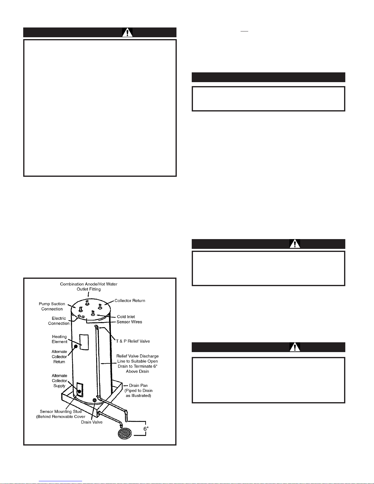
This water heater is designed to be used only with forced circulation. The
pump may be mounted directly on top of the unit. The plumbing
professional installing the water heater has the option of using either the
top or side connections for the pump suction and collector return lines
(See Figure 1). If the side connections are used, the corresponding top
connections must be capped (plugged). Each water heater is
manufactured with plugs installed in the side connections. If the side
connections are to be used, the plugs installed at the factory must be
removed. Connect the inlet side of the pump to the line marked pump
suction connection. Connect the outlet of the pump to the inlet of the
solar connector. The outlet of the collector should be connected to the
fitting marked collector return.
The two fittings on top not
used for the pump suction and collector return
lines are for connecting the cold water inlet supply and the hot water
outlet supply.
Ableed valve shall be installed in the system above the level of the pump
in order to bleed the air out of the water lines.
If this water is installed on a system utilizing any heat transfer solution
other than potable water, a separate heat exchanger must be installed. A
qualified heat exchanger must be constructed in such a manner that failure
of the heat exchanger will not result in contamination of the potable water.
If a separate heat exchanger is used, forced circulation must be used
between the heat exchanger and the solar storage unit. Using either the
top or side connections, connect the inlet of the pump to the pump suction
connection and return line from the heat exchanger to the collector return
connection.
After the installation of all water lines is complete, open the main water
supply valve and fill the heater. Open several hot water faucets to allow
air to escape from the system while the water heater is filling. When
water passes through all the faucets, close the faucets and check for
possible leaks in the system.
This water heater can deliver scalding temperature water at any faucet in
the system. Be careful whenever using hot water to avoid scalding injury.
Certain appliances, such as dishwashers and automatic clothes washers
may require increased temperature water. By setting the thermostat on
this water heater to obtain increased temperature water required by these
appliances, you may create the potential for scald injury.
To protect against injury, you should install an anti-scald tempering valve
in the water system. This valve will reduce point of discharge
temperature by mixing cold and hot water in branch supply lines. Such
lines are available from the local plumbing supplier. Please consult with
a plumbing professional.
Under certain conditions, water in this water heater may become
excessively hot. It is recommended that a thermostatically
controlled tempering valve may be installed in the outlet line to
reduce the risk of scald injury by preventing point of discharge
water temperatures in excess of 140°F (60°C).
CAUTION
Increasing the thermostat setting above the preset temperature
may cause severe burns and consume excessive energy. Hotter
water increases the risk of scald injury.
CAUTION
This water heater does not contain a heat exchanger, therefore,
only potable water may be allowed to enter the water heater.
IMPORTANT
Install the combination temperature and pressure relief valve into the
opening provided and marked for this purpose on the water heater.
Install a discharge line so that water discharged from the
combination temperature and pressure relief valve will exit within 6
in. (15.3 cm) above, or any distance below the structural floor and
cannot contact any live electrical part. The discharge line is to be
installed to allow for complete drainage of both the temperature and
pressure relief valve and the discharge line. The discharge opening
must not be subjected to blockage or freezing. DO NOTthread, plug
or cap the discharge line. It is recommended that a minimum of 4 in.
(10.2 cm) be provided on the side of the water heater for servicing
and maintenance of the combination temperature and pressure relief
valve.
Do not place a valve between the combination temperature and
pressure relief valve and the tank.
WARNING
2
Figure 1
Page 3

ELECTRICAL CONNECTIONS
Before any electrical connections are made, be sure that the water heater
is full of water and that the manual shut-off valve in the cold water supply
line is open. Check the rating plate and wiring diagram before
proceeding. This solar electric water heater was built and wired in
accordance with the Underwriters Laboratories testing approvals
requirements. The temperature limiting device is of the manual reset,
trip-free type and has been factory installed to interrupt all ungrounded
power supply conductors in the event of thermostat failure. Thermostats
are factory set and wired in accordance with the wiring diagram fastened
to the inside of the top access panel. The plumbing supplier in your area
ordered this water heater wired at the factory to comply with the existing
area codes, but local utility codes may require or allow other circuitry.
Consult your local power company to determine the correct electrical
hook-up in order to meet local utility and building codes and in order to
obtain the most economical rates. Also check to find out if you are
required to obtain a permit before starting the installation. The following
chart shows the recommended fuse size for the maximum water heater
wattage. The maximum wattage and rated voltage are shown on the water
heater data plate. The water heater must be well grounded. A green
ground screw is provided at the electrical connection point for
connecting a ground wire.
The controller may be mounted directly on the top of the solar storage unit.
Wires are provided from the sensor mounting stud to the top of the water
heater. Attach the tank sensor to these wires and mount the sensor to the
tank using the stud provided on the tank. This stud is located under the
cover on the lower front of the water heater. A tank sensor may be
provided as an option, in which case, it may be pre-mounted and wired.
Attach the wires through the top of the unit to the terminals on the Solar
Differential Control.
Before closing the switch to allow electric current to flow to the water
heater, make certain that the water heater is full of water and that the cold
water inlet valve is open. Complete failure of the heating element will
result if it is not totally immersed in water at all times. When the switch
is closed, the operation of this solar electric water heater is automatic. The
thermostats are preset to the “HOT” setting to provide a water
temperature of approximately 120°F (49°C) to reduce the risk of scald
injury.
Care must be taken whenever using hot water to avoid scalding injury.
Certain appliances require high temperature hot water (such as
dishwashers and automatic clothes washers).
TO FILL THE WATER HEATER:
1. Close the water heater drain valve by turning the knob clockwise.
2. Open the cold water supply shut-off valve.
3. Open several hot water faucets to allow air to escape from the system.
4. When a steady stream of water flows from the faucets, the water heater
is filled. Close the faucets and check for water leaks at the water heater
drain valve, combination temperature and pressure relief valve and the hot
and cold water connections.
TO DRAIN THE HEATER:
Should it become necessary to completely drain the water heater, make
sure you adhere to the following steps:
500 10A 5A 5A
1000 15A 10A 10A
1250 15A 10A 10A
1500 20A 10A 10A
2000 25A 15A 10A
2500 30A 15A 15A
3000 35A 20A 20A
3500 40A 20A 20A
4000 35A 25A
4500 30A 25A
5000 35A 30A
5500 35A 35A
6000 40A 35A
MAX VOLTS
MAX
WATTS 120V 208V 240V
RECOMMENDED FOR AMPERAGE
Water temperatures over 125°F (52°C) can cause severe burns
instantly or death from scalds. Children, disables, and elderly
are at highest risk of being scalded. See “Temperature
Adjustment” section of this manual before setting thermostat at
water heater. Feel water before bathing or showering.
Temperature limiting valves are available; consult local
plumbing supplier.
DANGER
3
Page 4

1. Disconnect the power supply to the heater. Consult the plumber or
electric company in your area for service.
2. Close the cold water supply shut-off valve.
3. Open the drain valve on the water heater by turning the knob counterclockwise. The drain valve has threads on the end that will allow
connection of a standard hose coupling.
Open a hot water faucet to allow air to enter the system.
TEMPERA TURE ADJUSTMENT
The temperature of the water can be changed by adjusting the
thermostat(s). Before any work is done on the water heater, disconnect all
power to the water heater by opening the switch at the main electrical
circuit breaker or fuse box. Remove the access panels or front panel on
table tops, fold the insulation outward away from the controls. Set the
thermostat(s) to the desired water temperature using a screwdriver to
move the thermostat pointer. The thermostat has been factory preset to
approximately 120°F (49°C). Rotate the temperature dial clockwise to
increase water temperature. Replace the insulation making sure that the
controls are well covered and that the plastic terminal shield has not been
displaced; replace the access panel. The water heater is now ready for
operation and the main switch can be closed.
Shut off the electric power and water supply, drain the heater completely
to prevent freezing whenever the building is left unoccupied during the
cold weather months. In order to ensure efficient operation and long tank
life, drain the heater through the drain valve until water runs clear. Drain
it at least once a month. Failure to do this may result in noisy operation
and lime and sediment buildup in the bottom of the tank. Check the
temperature and pressure relief valve to ensure that the valve has not
become encrusted with lime. Lift the lever at the top of the valve several
times until valve seats properly without leaking and operates freely.
Contact your supplier or plumbing professional for replacement parts or
contact the company at the address displayed on the rating plate of the
water heater.
For faster and better service, please provide the part name, model, and
serial number(s) of the water heater(s) when ordering parts.
READ THE WARRANTY FOR A FULLEXPLANATION OF THE
LENGTH OF TIME THAT PARTS AND THE WATER HEATER
ARE WARRANTED.
Complete the following information and retain for future reference:
Model No.:______________________________________________
Serial No.:_______________________________________________
Installer:________________________________________________
Date of Installation:_______________________________________
For your safety, DONOT attempt to repair thermostat(s),
heating elements, or electrical wiring. Refer such repairs to a
qualified service technician.
CAUTION
When lifting the level of the temperature-pressure relief valve,
hot water will be released under pressure. Be certain that any
released water does not result in bodily injury or property
damage. The magnesium anode rod should be inspected
periodically and replaced when necessary to prolong tank life.
WARNING
The water heater should be inspected at a minimum of annually
by a qualified service technician for damaged components. DO
NOT operate this water heater if any part is found damaged.
IMPORTANT
Hotter water increases the risk of scald injury. Scalding may
occur within five (5) seconds at a temperature setting of 135°F
(57°C). To protect against hot water injury, install an anti-scald
tempering valve in the water system. This valve will reduce
point of discharge water temperatures by mixing cold and hot
water in branch water lines. A licensed plumbing professional
or local plumbing authority should be consulted.
Note: This water heater is equipped with an energy cut out
device to prevent overheating. Should overheating occur, turn
off the electrical supply to the water heater and contact a
qualified service technician.
DANGER
Before adjusting the thermostat(s), turn off power supply to the
water heater.
CAUTION
4
CP-1M-2/03-Printed in U.S.A.
 Loading...