

Lochinvar Mini Copper-Fin MCW226CE, Mini Copper-Fin MCW271CE, Mini Copper-Fin MCW316CE, Mini Copper-Fin MCW361CE, Mini Copper-Fin MCW501CE Installation, Commissioning And Maintenance Instructions
...
MCW91CE
MCB501CE
INS0023 Issue No 6 | August 2011
The Mini Copper-Fin® range
High Efficiency Gas Fired Water Heaters and
Boilers
Installation, Commissioning and
Maintenance Instructions
Models:
MCW136CE
MCW181CE
MCW226CE
MCW271CE
MCW316CE
MCW361CE
MCW401CE
MCW501CE
MCB91CE
MCB136CE
MCB181CE
MCB226CE
MCB271CE
MCB316CE
MCB361CE
MCB401CE

2
Table of Contents
1.0 INTRODUCTION ...................................................................................................................................................................................................................................... 4
2.0 PRINCIPAL PARTS ................................................................................................................................................................................................................................. 5
3.0 TECHNICAL DATA .................................................................................................................................................................................................................................. 7
4.0 GENERAL REQUIREMENTS .................................................................................................................................................................................................................. 9
4.1 RELATED DOCUMENTS ................................................................................................................................................................................................................. 9
5.0 WATER QUALITY .................................................................................................................................................................................................................................. 10
6.0 LOCATION ............................................................................................................................................................................................................................................. 10
6.1 PLANT ROOM VENTILATION ....................................................................................................................................................................................................... 10
6.2 GENERAL REQUIREMENTS ......................................................................................................................................................................................................... 10
6.3 CLEARANCES ................................................................................................................................................................................................................................ 10
7.0 GAS SUPPLY ......................................................................................................................................................................................................................................... 11
7.1 SERVICE PIPES ............................................................................................................................................................................................................................. 11
7.2 METERS.......................................................................................................................................................................................................................................... 11
7.3 GAS SUPPLY PIPES ...................................................................................................................................................................................................................... 11
7.4 BOOSTED SUPPLIES .................................................................................................................................................................................................................... 11
7.5 PLANT-ROOM CONTROL VALVE ................................................................................................................................................................................................ 11
7.6 EQUIPMENT GAS SYSTEM LEAK CHECK .................................................................................................................................................................................. 11
8.0 FLUE SYSTEM ....................................................................................................................................................................................................................................... 12
8.1 FLUE SYSTEM GENERAL REQUIREMENTS .............................................................................................................................................................................. 12
8.2 FLUE SYSTEMS ............................................................................................................................................................................................................................. 12
8.3 FLUE MATERIALS – CONVENTIONAL FLUE INSTALLATIONS ................................................................................................................................................ 12
8.4 MULTIPLE FLUE INSTALLATION ................................................................................................................................................................................................. 13
8.5 FAN DILUTION SYSTEMS ............................................................................................................................................................................................................. 13
8.6 B ALA NCED COMPARTME NT S ..................................................................................................................................................................................................... 13
9.0 AIR SUPPLY .......................................................................................................................................................................................................................................... 13
9.1 NATURAL VENTILATION............................................................................................................................................................................................................... 13
9.2 MECHANICAL VENTILATION........................................................................................................................................................................................................ 14
10.0 WATER CONNECTIONS ....................................................................................................................................................................................................................... 16
10.1 WATER HEATERS ......................................................................................................................................................................................................................... 16
10.1.1 GENERAL ........................................................................................................................................................................................................................ 16
10.1.2 OPEN VENTED SYSTEM ARRANGEMENT ................................................................................................................................................................. 16
10.1.3 UNVENTED SYSTEM ARRANGEMENT ....................................................................................................................................................................... 16
10.1.4 WATER PRESSURE GAUGE ......................................................................................................................................................................................... 16
10.1.5 DRAIN VALVES ............................................................................................................................................................................................................... 16
10.1.6 EXPANSION VESSEL SIZING ....................................................................................................................................................................................... 17
10.1.7 DE-STRATIFICATION ..................................................................................................................................................................................................... 17
10.1.8 CIRCULATING PUMPS .................................................................................................................................................................................................. 17
10.1.9 PIPEWORK SIZE ............................................................................................................................................................................................................ 18
10.2 HEATING BOILERS........................................................................................................................................................................................................................ 19
10.2.1 GENERAL ........................................................................................................................................................................................................................ 19
10.2.2 OPEN VENTED SYSTEM ARRANGEMENT ................................................................................................................................................................. 19
10.2.3 SEALED SYSTEM ARRANGEMENT ............................................................................................................................................................................. 19
10.2.4 DRAIN VALVES ............................................................................................................................................................................................................... 19
10.2.5 EXPANSION VESSEL SIZING ....................................................................................................................................................................................... 20
10.2.6 PRIMARY CIRCULATING PUMPS ................................................................................................................................................................................. 20
10.3 POOL HEATING ............................................................................................................................................................................................................................. 21
10.4 FLOW SWITCH ............................................................................................................................................................................................................................... 21
11.0 ELECTRICAL SUPPLY ......................................................................................................................................................................................................................... 21
11.1 E LECTRICAL CONNECT IONS ...................................................................................................................................................................................................... 22
11.2 EXTERNAL CONTROLS ................................................................................................................................................................................................................ 22
11.3 ARC WELDING PRECAUTIONS ................................................................................................................................................................................................... 22
11.4 WI RI NG DI AGRAM ......................................................................................................................................................................................................................... 23
12.0 COMMISSIONING AND TESTING ........................................................................................................................................................................................................ 25
12.1 E LE CTRICAL INSTA LLATION ....................................................................................................................................................................................................... 25
12.2 GAS INSTALLATION ...................................................................................................................................................................................................................... 25
12.3 WA T ER CO N NE CTIONS ............................................................................................................................................................................................................... 25
12.4 COMMISSIONING THE EQUIPMENT ........................................................................................................................................................................................... 25
12.4.1 GENERAL CHECKS PRIOR TO LIGHTING .................................................................................................................................................................. 25
12.4.2 EQUIPMENT CHECKS PRIOR TO LIGHTING .............................................................................................................................................................. 25
12.4.3 PROCEDURE FOR INITIAL LIGHTING ......................................................................................................................................................................... 26
12.4.4 GAS PRESSURE ADJUSTMENT AND COMBUSTION CHECKS................................................................................................................................ 26
12.5 WATER HEATER TEMPERATURE ADJUSTMENT PROCEDURE ............................................................................................................................................ 27
12.6 BOILER TEMPERATURE ADJUSTMENT PROCEDURE ............................................................................................................................................................ 27
12.7 INSTALLATION NOISE .................................................................................................................................................................................................................. 27
13.0 LPG FUEL .............................................................................................................................................................................................................................................. 27
13.1 RELATED DOCUMENTS ............................................................................................................................................................................................................... 27
13.2 PROPANE INJECTORS ................................................................................................................................................................................................................. 28
13.3 CONVERSION TO LPG .................................................................................................................................................................................................................. 28
13.4 LPG COMMISSIONING AND TESTING ........................................................................................................................................................................................ 28

3
14.0 MAINTENANCE ..................................................................................................................................................................................................................................... 28
14.1 GENERAL ....................................................................................................................................................................................................................................... 28
14.2 MAINTENANCE SCHEDULE ......................................................................................................................................................................................................... 29
14.2.1 ADDITIONAL REQUIREMENTS FOR WATER HEATERS ........................................................................................................................................... 29
14.3 DRAINING THE WATER SYSTEM ................................................................................................................................................................................................ 29
14.4 WATER HEATER SERVICING ...................................................................................................................................................................................................... 29
14.4.1 REMOVING SCALE AND SEDIMENT FROM THE STORAGE VESSEL ..................................................................................................................... 29
14.4.2 SACRIFICIAL MAGNESIUM ANODES .......................................................................................................................................................................... 29
14.5 CLEANING THE HEAT EXCHANGER .......................................................................................................................................................................................... 30
14.6 REFILLING THE SYSTEM ............................................................................................................................................................................................................. 31
14.7 OTHER CHECKS ............................................................................................................................................................................................................................ 32
14.7.1 RELIEF VALVES ............................................................................................................................................................................................................. 32
14.7.2 FLUE SYSTEM ................................................................................................................................................................................................................ 32
14.8 TTB DEVICE ................................................................................................................................................................................................................................... 32
14.9 FAULT FINDING ............................................................................................................................................................................................................................. 32
15.0 USER INSTRUCTIONS .......................................................................................................................................................................................................................... 33

4
1.0 INTRODUCTION
• The Lochinvar Mini Copper-Fin range is a floor standing direct gas fired water heater or boiler. The
equipment comprises a copper finned tube heat exchanger surrounded with a high density, light weight
refractory insulation. A durable outer steel jacket assembly provides structural integrity and easy
disassembly. The gas train includes black iron inlet manifold(s) a nd stainless steel atmospheric burner
assemblies.
• The burners are initiated by a full ignition sequence control that incorporates an intermittent pilot
assembly and rectification supervision of the flame.
• For the correct operation of the appliance when used as a water heater, it is essential that a suitably
sized, glanded-construction bronze pump is utilised to maintain a constant water flow rate through the
heat exchanger. When used as a water heater, the M ini Copper-Fin should also be used in conjunction
with an appropriately sized storage vessel (available from Lochinvar Limited as an ancillary option).
• This equipment is intended for use on Group H Natural Gas (2
The information relating to propane firing is to be found in Section 13: LPG FUEL. This equipment
MUST NOT use gas other than that for which it has been designed and adjusted.
• This equipment must be installed by a competent person, registered with a H.S.E. approved body. All
installations must conform to the relevant Gas Safety and Building Regulations. Health & Safety
requirements must also be taken into account when installing any equipment. Failure to comply with the
above may lead to prosecution.
• If the equipment is to be connected to an unvented (pressurised) system, care must be taken to ensure
all extra safety requirements are satisfied should a high or low-pressure condition occur in the system.
• The equipment is designed for direct connection to a flue system via the draught diverter built in to the
equipment casing. The flue outlets from more than one unit may be connected to a single chimney.
• Ancillary Options:
• Primary Circulating Pump (MCW91-361CE) Omega 4-60-2ZS
• Primary Circulating Pump (MCW401-501CE) Omega 4-90-2ZS
• Direct Storage Cylinder (297 litre) LST66
• Direct Storage Cylinder (450 litre) LST100
• Direct Storage Cylinder (747 litre) LST166
• Direct Storage Cylinder (1155 litre) LST250
• Unvented/Boosted Water System Kits Contact Lochinvar Limited
• De-stratification Pump Kit WH9
• Pre-Fabricated Interconnecting Pipework Contact Lochinvar Limited
• Stacking Frame (MCW/MCB91-181CE) MSF3050
• Stacking Frame (MCW/MCB226-361CE) MSF3051
• Stacking Frame (MCW/MCB401-501CE) MSF3052
• Stacking Frame (MCW + Storage) Contact Lochinvar Limited
nd
Family) and LPG propane (3rd Family).
5
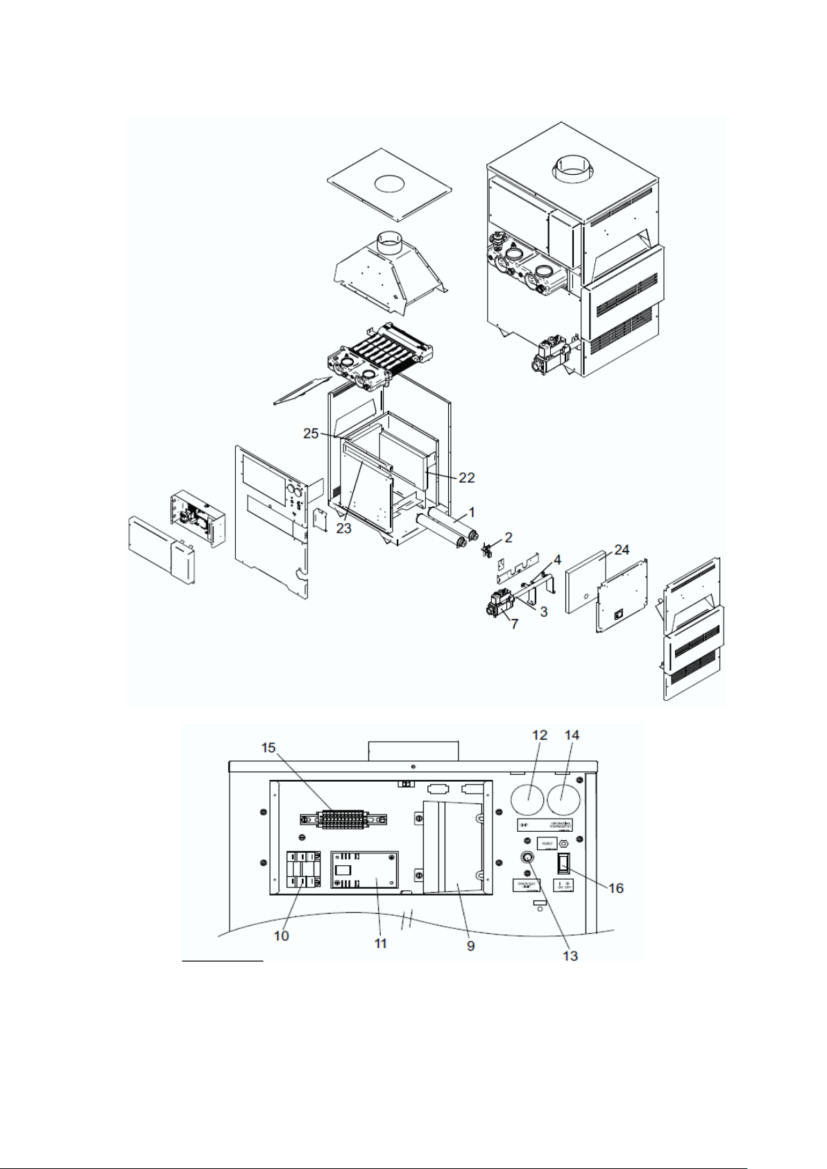
2.0 PRINCIPAL PARTS
FIGURE 2.1 EXPLODED DIAGRAM
FIGURE 2.2 EXPLODED DIAGRAM – CONTRO L PANEL ASSEMBLY
6
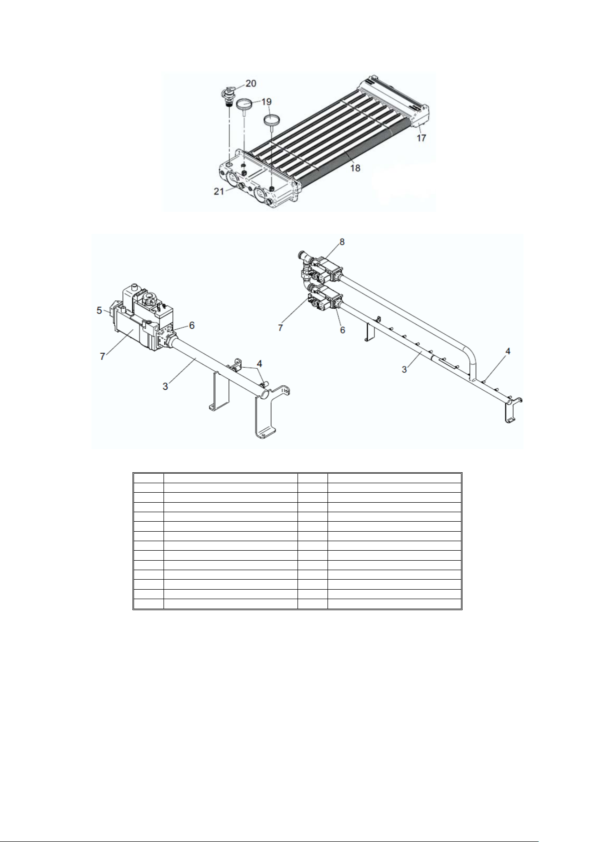
FIGURE 2.3 EXPLODED DIAGRAM – HEAT EXCHANGER
ITEM
DESCRIPTION
ITEM
DESCRIPTION
1
Main burner bar
14
Control thermostat
2
Pilot burner assembly
15
Terminal str ip
3
Burner manifold
16
On/off switch
4
Main burner injector
17
Heat exchan ger
5
Gas inlet flange
18
‘V’ baffle
6
Manifold fla nge
19
Temperature gauge
7
Gas valve
20
Pressure/temperature relief valve
8
Gas valve
21
Bulbwell pocket
9
Sequence cont rol
22
Right side fi bre board
10
Relay
23
Left side fibre board
11
Time delay relay
24
Front fibre b oard
12
High limit thermostat
25
Rear fibre board
13
Overheat thermostat
FIGURE 2.4 EXPLODED DIAGRAM - GAS MANIFOLD ASSEMBLY
TABLE 2.1 REMOVABLE COMPONENTS

7
3.0 TECHNICAL DATA
Model Number
MC91CE
MC136CE
MC181CE
MC226CE
MC271CE
MC316CE
MC361CE
MC401CE
MC501CE
GENERAL DATA
Input (gross) - kW
26.4
39.6
52.8
65.9
79.1
92.3
105.5
117.2
146.5
Input (net) - kW
23.8
35.6
47.0
59.4
71.3
83.1
95.1
105.6
132.0
Output - kW (80°/60°)
20.8
31.0
41.4
52.3
62.7
73.2
83.6
93.0
118.8
Recovery Rat e (44° ∆T) - l/hr
432
648
864
1044
1260
1476
1692
1872
2340
Recovery Rat e (50° ∆T) - l/hr
380
570
760
919
1109
1299
1489
1647
2059
Shipping Weight - kg
57
64
71
84
89
99
104
127
132
WATER DATA
Water content - litres
3
3.2
3.4
3.5
3.6
3.7
3.8
4.2
4.5
Water connections (F&R) –
“BSP
Max. Water Pr essure - bar
11
11
11
11
11
11
11
11
11
Min. Water Pressure - bar
0.5
0.5
0.5
0.5
0.5
0.5
0.5
0.5
0.5
Maximum water temperature
Maximum water temperature
(boilers) - °C
GAS DATA (G20)
Gas inlet connection – “BSP
¾”
¾”
¾”
¾”
¾”
¾”
¾”
¾”
1”
Gas Flow Rate - m3/hr
2.51
3.77
5.03
6.27
7.53
8.79
10.05
11.16
13.91
Burner Pressure - mbar
8.7
8.7
8.7
8.7
8.7
8.7
8.7
8.7
8.7
Minimum Gas Inlet Pressure mbar
Maximum Gas Inlet Pressure -
GAS DATA (G31)
Gas inlet connection – “BSP
¾”
¾”
¾”
¾”
¾”
¾”
¾”
¾”
1”
Gas Flow Rate - m3/hr
0.99
1.49
1.98
2.48
2.97
3.47
3.97
4.41
5.51
Burner Pressure - mbar
26.0
26.0
26.0
26.0
26.0
26.0
26.0
26.0
26.0
Minimum Gas Inlet Pressure mbar
Maximum Gas Inlet Pressure mbar
FLUE DATA
Flue spigot diameter - mm
126
152
178
178
200
200
228
250
250
Flue gas volume - m3/min
0.79
1.25
1.64
2.07
2.52
2.92
3.39
3.79
4.73
Maximum flue gas temp. - ⁰C
140
140
130
130
160
160
160
160
160
2 2 2 2 2 2 2 2 2
(water heaters) - °C
mbar
90 90
105 105 105 105 105 105 105 105 105
17.5 17.5 17.5 17.5 17.5 17.5 17.5 17.5 17.5
25 25 25 25 25 25 25 25 25
27 27 27 27 27 27 27 27 27
45 45 45 45 45 45 45 45 45
90 90 90 90 90 90 90
TABLE 3.1: TECHNICAL DATA
8
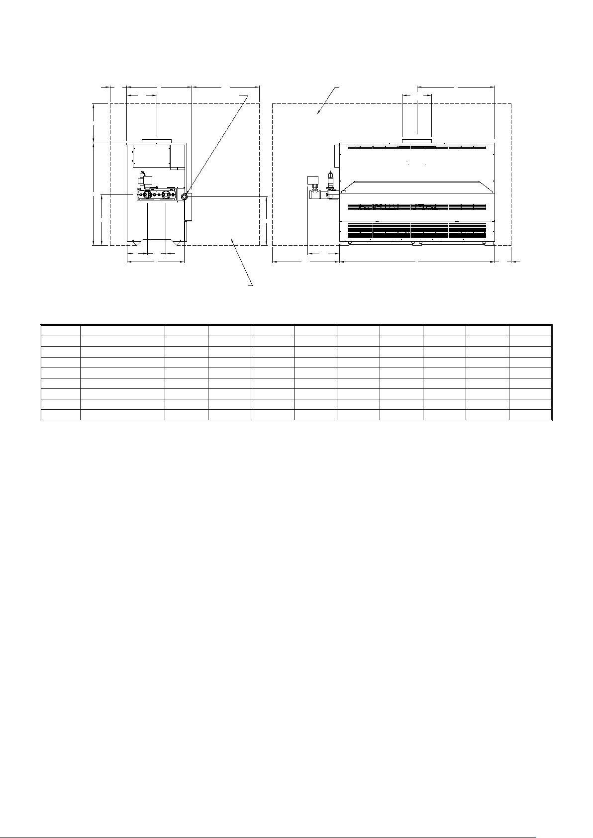
Dimension
Description
MC91CE
MC136CE
MC181CE
MC226CE
MC271CE
MC316CE
MC361CE
MC401CE
MC501CE
A
Overall height of heater
750
750
750
750
750
750
750
750
876
B
Overall width of heater
394
495
597
673
749
825
902
1130
1334
C
Overall depth of heater
546
546
546
546
546
546
546
559
559
D
Centreline of flue
197
248
298
337
375
413
451
565
667
E
Flue diameter
126
152
178
178
203
203
228
254
254
F
Height of ga s inlet
171
171
171
171
171
171
171
171
321
G
Centreline of gas inlet
475
475
475
475
475
475
475
475
493
H
Service clearance above
355
355
355
737
737
737
737
737
737
152
H
A
432
260
OUTLET
C
INLET
610
GAS CONNECTION
RECOMMENDED CLEARANCES
F
E DIA
D
178 159
G
(TO CENTRE OF GAS INLET)
RECOMMENDED CLEARANCES
263
610
FIGURE 3.1: DIMENSIONS
TABLE 3.1: DIMENSIONS
B
152

9
4.0 GENER AL REQUIREMENTS
The Lochinvar Mini Copper-Fin has been designed to operate trouble free for many years. These instructions
should be followed closely to obtain the maximum usage and efficiency of the equipment. PLEASE read the
instructions fully before installing or using the appliance.
4.1 RELATED DOCUMENTS
It is law that all gas appliances are installed by competent persons, in accordance with The Gas Safety
(Installation and Use) Regulations 1998. Failure to install appliances correctly could lead to prosecution. It is in
your own interest, and that of safety, to ensure that this law is complied with.
The installation of the equipment MUST be in accordance with the relevant requirements of the Gas Safety
Regulations, Building Regulations, I.E.E. Regulations and the bylaws of the local water undertaking. The
installation should also be in accordance with any relevant requirements of the local gas distributor and local
authority.
In addition the installation should follow the relevant guidance offered in the following documents. It is not
practical to list all relevant information but emphasis is placed on the following documents, as failure to comply
with the guidance given will almost certainly result in an unsatisfactory installation:
BS EN 1858: 2003 Chimneys. Components. Concrete flue blocks
BS 5440-1: 2008 Installation and maintenance of flues and ventilation for gas appliances of rated input
not exceeding 70kW net (1st, 2nd and 3rd family gases)
Part 1: Specification for installation and maintenance of flues
BS 5440-2: 2009 Installation and maintenance of flues and ventilation for gas appliances of rated input
not exceeding 70kW net (1st, 2nd and 3rd family gases)
Part 2: Specification for installation and maintenance of ventilation for gas
appliances
BS 6644: 2005 Specification for Installation of g as fired hot water boilers of rated inputs between
70kW
nd
+ A1: 2008 (net) and 1.8MW (net) (2
and 3rd family gasses)
BS 6700: 1997 Design, installation, testing and maintenance of services supplying water for
domestic use within buildings and their curtilages
BS 6880: 1988 Code of practice for low temperature hot water systems of output greater than 45kW
Parts 1, 2 and 3
BS 7074: 1989 Application, selection and installation of expansion vessels and ancillary equipment
Parts 1and 2 for sealed systems
BS 7671: 2008 Requirements for electrical installations, I.E.E. wiring regulations seventeenth edition
CP 342: Code of practice for centralised hot water supply-buildings other than dwellings
Part 2 1974
IGE/UP/1: Installation pipework on industrial and commercial premises
Edition 2
IGE/UP/2: Gas installation pipework, boosters and compressors on industrial and commercial
Edition 2 premises

10
IGE/UP/4: Commissioning of gas fired plant on industrial and commercial premises
Edition 2
IGE/UP/10: Installation of flued gas appliances in industrial and commercial premises
Edition 3
Gas Safety (Installation and Use) Regulations 1998 (England, Scotland & Wales)
CIBSE: Guide parts A, B and C
H.S.E. guidance Automatically controlled steam and hot water boilers
note PM5:
Third edition of the 1956 Clean Air Act Memorandum on Chimney Heights
Manufacturer's notes must not be taken in any way as overriding statutory obligations.
5.0 WATER QUALITY
Water supply quality may adversely affect the efficiency and performance of water heaters and hot water systems.
The situation can intensify where higher temperatures or demands exist.
Water hardness should not exceed 205ppm CaCO
and TDS (Total Dissolved Solids) of untreate d water should
3
not exceed 350ppm. If these values are exceeded, contact Lochinvar Limited for further guidance.
6.0 LOCATION
6.1 PLANT ROOM VENTILATION
The Lochinvar Mini Copper-Fin may only be installed in a room that complies with the appropriate ventilation
requirements. For further details, please refer to Section 9: AIR SUPPLY or to BS5440-2 or BS6644 as
appropriate.
6.2 GENERAL REQUIREMENTS
Corrosion of the heat exchanger and flue system may occur if air for combustion contains certain chemical
vapours. Such corrosion may result in poor combustion and create a risk of asphyxiation. Aerosol propellants,
cleaning solvents, refrigerator and air conditioning refrigerants, swimming pool chemicals, calcium and sodium
chloride, waxes and process chemicals are corrosive. Products of this sort should not be stored near the water
heater or outside by the air intake (if applicable). The fitting of this equipment in a situation where aerosols or
other chemicals may be entrained into the combustion air will invalidate the warranty.
The equipment must be installed on a level, non-combustible surface that is capable of adequately supporting its
weight (when filled with water) and any ancillary equipment. The operation of the equipment must not cause the
temperature of any combustible material in the vicinity of the equipment and its flue to exceed 65 °C. If such a
situation is unavoidable, appropriate insulation should be provided.
Locate the equipment so that if the appliance or any connecting pipework should leak, water damage will not
occur. When such locations cannot be avoided it is recommended that a suitable drain pan be installed under the
equipment. The pan should be adequately drained but must not restrict the combustion or ventilation airflow.
6.3 CLEARANCES
The location chosen for the equipment must permit the provision for a satisfactory flue system and an adequate air
supply. The location must also provide adequate space for servicing and air circulation around each unit. This
includes any electrical trunking laid across the floor and to the appliance.
See Figure 3.1 and Table 3.1 for dimensions and clearances. Further details regarding locations are given in
BS5440 or BS6644 as appropriate.

11
7.0 GAS SU PPLY
The Lochinvar Mini Copper-Fin range is suitable for use on second and third family gasses 2H - G20 - 20mbar and
3P - G31 - 37mbar. Details relating to Natural Gas (2H) appear below; for details relating to Propane (3P)
please refer to Section 13: LPG FUEL.
7.1 SERVICE PIPES
The local gas distributor must be consulted at the installation planning stage in order to establish the availability of
an adequate supply of gas. An existing service pipe must not be used without prior consultation with the local gas
distributor.
7.2 METERS
A new gas meter will be connected to the service pipe by the local gas distributor contractor. An existing gas
meter should be checked, preferably by the gas distributor, to ensure that it is adequate to deal with the rate of gas
supply required.
7.3 GAS SUPPLY PIPES
Supply pipes must be fitted in accordance with IGE/UP/2. Pipework from the meter to the equipment must be of
adequate size. The complete installation must be purged and tested as described in IGE/UP/1. Refer to Section
13: LPG FUEL for information on LPG pipework installation guidance.
7.4 BOOSTED SUP PLIES
Where it is necessary to employ a gas pressure booster, the controls must include a low-pressure cut-off switch at
the booster inlet. The local gas distributor must be consulted before a gas pressure booster is fitted. For details of
how to connect a low-pressure cut-off switch, please refer to Section 11: ELECTRICAL SUPPLY.
7.5 PLANT-ROOM CONTROL VALVE
A manual valve for plant-room isolation must be fitted in the gas supply line. It must be clearly identified and
readily accessible for operation, preferably by an exit.
7.6 EQUIPMENT G AS SYSTEM LEAK CHECK
An approved isolating valve and union should be installed for each unit in a convenient and safe position
and be clearly marked. Ensure that the manual gas service valve is in the OFF position. Although the
equipment receives a gas leak check and gas train component integrity check prior to leaving the factory, transit
and installation may cause disturbance to unions, fittings and components. During commissioning a further test
for tightness should be carried out on the equipment gas pipework and components.
Care must be taken not to allow leak detection fluid on or near any electrical parts or connections.
 Loading...