

Lochinvar Mini Copper-Fin MCW226CE, Mini Copper-Fin MCW271CE, Mini Copper-Fin MCW316CE, Mini Copper-Fin MCW361CE, Mini Copper-Fin MCW501CE Installation, Commissioning And Maintenance Instructions
...Page 1
MCW91CE
MCB501CE
INS0023 Issue No 6 | August 2011
The Mini Copper-Fin® range
High Efficiency Gas Fired Water Heaters and
Boilers
Installation, Commissioning and
Maintenance Instructions
Models:
MCW136CE
MCW181CE
MCW226CE
MCW271CE
MCW316CE
MCW361CE
MCW401CE
MCW501CE
MCB91CE
MCB136CE
MCB181CE
MCB226CE
MCB271CE
MCB316CE
MCB361CE
MCB401CE
Page 2

2
Table of Contents
1.0 INTRODUCTION ...................................................................................................................................................................................................................................... 4
2.0 PRINCIPAL PARTS ................................................................................................................................................................................................................................. 5
3.0 TECHNICAL DATA .................................................................................................................................................................................................................................. 7
4.0 GENERAL REQUIREMENTS .................................................................................................................................................................................................................. 9
4.1 RELATED DOCUMENTS ................................................................................................................................................................................................................. 9
5.0 WATER QUALITY .................................................................................................................................................................................................................................. 10
6.0 LOCATION ............................................................................................................................................................................................................................................. 10
6.1 PLANT ROOM VENTILATION ....................................................................................................................................................................................................... 10
6.2 GENERAL REQUIREMENTS ......................................................................................................................................................................................................... 10
6.3 CLEARANCES ................................................................................................................................................................................................................................ 10
7.0 GAS SUPPLY ......................................................................................................................................................................................................................................... 11
7.1 SERVICE PIPES ............................................................................................................................................................................................................................. 11
7.2 METERS.......................................................................................................................................................................................................................................... 11
7.3 GAS SUPPLY PIPES ...................................................................................................................................................................................................................... 11
7.4 BOOSTED SUPPLIES .................................................................................................................................................................................................................... 11
7.5 PLANT-ROOM CONTROL VALVE ................................................................................................................................................................................................ 11
7.6 EQUIPMENT GAS SYSTEM LEAK CHECK .................................................................................................................................................................................. 11
8.0 FLUE SYSTEM ....................................................................................................................................................................................................................................... 12
8.1 FLUE SYSTEM GENERAL REQUIREMENTS .............................................................................................................................................................................. 12
8.2 FLUE SYSTEMS ............................................................................................................................................................................................................................. 12
8.3 FLUE MATERIALS – CONVENTIONAL FLUE INSTALLATIONS ................................................................................................................................................ 12
8.4 MULTIPLE FLUE INSTALLATION ................................................................................................................................................................................................. 13
8.5 FAN DILUTION SYSTEMS ............................................................................................................................................................................................................. 13
8.6 B ALA NCED COMPARTME NT S ..................................................................................................................................................................................................... 13
9.0 AIR SUPPLY .......................................................................................................................................................................................................................................... 13
9.1 NATURAL VENTILATION............................................................................................................................................................................................................... 13
9.2 MECHANICAL VENTILATION........................................................................................................................................................................................................ 14
10.0 WATER CONNECTIONS ....................................................................................................................................................................................................................... 16
10.1 WATER HEATERS ......................................................................................................................................................................................................................... 16
10.1.1 GENERAL ........................................................................................................................................................................................................................ 16
10.1.2 OPEN VENTED SYSTEM ARRANGEMENT ................................................................................................................................................................. 16
10.1.3 UNVENTED SYSTEM ARRANGEMENT ....................................................................................................................................................................... 16
10.1.4 WATER PRESSURE GAUGE ......................................................................................................................................................................................... 16
10.1.5 DRAIN VALVES ............................................................................................................................................................................................................... 16
10.1.6 EXPANSION VESSEL SIZING ....................................................................................................................................................................................... 17
10.1.7 DE-STRATIFICATION ..................................................................................................................................................................................................... 17
10.1.8 CIRCULATING PUMPS .................................................................................................................................................................................................. 17
10.1.9 PIPEWORK SIZE ............................................................................................................................................................................................................ 18
10.2 HEATING BOILERS........................................................................................................................................................................................................................ 19
10.2.1 GENERAL ........................................................................................................................................................................................................................ 19
10.2.2 OPEN VENTED SYSTEM ARRANGEMENT ................................................................................................................................................................. 19
10.2.3 SEALED SYSTEM ARRANGEMENT ............................................................................................................................................................................. 19
10.2.4 DRAIN VALVES ............................................................................................................................................................................................................... 19
10.2.5 EXPANSION VESSEL SIZING ....................................................................................................................................................................................... 20
10.2.6 PRIMARY CIRCULATING PUMPS ................................................................................................................................................................................. 20
10.3 POOL HEATING ............................................................................................................................................................................................................................. 21
10.4 FLOW SWITCH ............................................................................................................................................................................................................................... 21
11.0 ELECTRICAL SUPPLY ......................................................................................................................................................................................................................... 21
11.1 E LECTRICAL CONNECT IONS ...................................................................................................................................................................................................... 22
11.2 EXTERNAL CONTROLS ................................................................................................................................................................................................................ 22
11.3 ARC WELDING PRECAUTIONS ................................................................................................................................................................................................... 22
11.4 WI RI NG DI AGRAM ......................................................................................................................................................................................................................... 23
12.0 COMMISSIONING AND TESTING ........................................................................................................................................................................................................ 25
12.1 E LE CTRICAL INSTA LLATION ....................................................................................................................................................................................................... 25
12.2 GAS INSTALLATION ...................................................................................................................................................................................................................... 25
12.3 WA T ER CO N NE CTIONS ............................................................................................................................................................................................................... 25
12.4 COMMISSIONING THE EQUIPMENT ........................................................................................................................................................................................... 25
12.4.1 GENERAL CHECKS PRIOR TO LIGHTING .................................................................................................................................................................. 25
12.4.2 EQUIPMENT CHECKS PRIOR TO LIGHTING .............................................................................................................................................................. 25
12.4.3 PROCEDURE FOR INITIAL LIGHTING ......................................................................................................................................................................... 26
12.4.4 GAS PRESSURE ADJUSTMENT AND COMBUSTION CHECKS................................................................................................................................ 26
12.5 WATER HEATER TEMPERATURE ADJUSTMENT PROCEDURE ............................................................................................................................................ 27
12.6 BOILER TEMPERATURE ADJUSTMENT PROCEDURE ............................................................................................................................................................ 27
12.7 INSTALLATION NOISE .................................................................................................................................................................................................................. 27
13.0 LPG FUEL .............................................................................................................................................................................................................................................. 27
13.1 RELATED DOCUMENTS ............................................................................................................................................................................................................... 27
13.2 PROPANE INJECTORS ................................................................................................................................................................................................................. 28
13.3 CONVERSION TO LPG .................................................................................................................................................................................................................. 28
13.4 LPG COMMISSIONING AND TESTING ........................................................................................................................................................................................ 28
Page 3

3
14.0 MAINTENANCE ..................................................................................................................................................................................................................................... 28
14.1 GENERAL ....................................................................................................................................................................................................................................... 28
14.2 MAINTENANCE SCHEDULE ......................................................................................................................................................................................................... 29
14.2.1 ADDITIONAL REQUIREMENTS FOR WATER HEATERS ........................................................................................................................................... 29
14.3 DRAINING THE WATER SYSTEM ................................................................................................................................................................................................ 29
14.4 WATER HEATER SERVICING ...................................................................................................................................................................................................... 29
14.4.1 REMOVING SCALE AND SEDIMENT FROM THE STORAGE VESSEL ..................................................................................................................... 29
14.4.2 SACRIFICIAL MAGNESIUM ANODES .......................................................................................................................................................................... 29
14.5 CLEANING THE HEAT EXCHANGER .......................................................................................................................................................................................... 30
14.6 REFILLING THE SYSTEM ............................................................................................................................................................................................................. 31
14.7 OTHER CHECKS ............................................................................................................................................................................................................................ 32
14.7.1 RELIEF VALVES ............................................................................................................................................................................................................. 32
14.7.2 FLUE SYSTEM ................................................................................................................................................................................................................ 32
14.8 TTB DEVICE ................................................................................................................................................................................................................................... 32
14.9 FAULT FINDING ............................................................................................................................................................................................................................. 32
15.0 USER INSTRUCTIONS .......................................................................................................................................................................................................................... 33
Page 4

4
1.0 INTRODUCTION
• The Lochinvar Mini Copper-Fin range is a floor standing direct gas fired water heater or boiler. The
equipment comprises a copper finned tube heat exchanger surrounded with a high density, light weight
refractory insulation. A durable outer steel jacket assembly provides structural integrity and easy
disassembly. The gas train includes black iron inlet manifold(s) a nd stainless steel atmospheric burner
assemblies.
• The burners are initiated by a full ignition sequence control that incorporates an intermittent pilot
assembly and rectification supervision of the flame.
• For the correct operation of the appliance when used as a water heater, it is essential that a suitably
sized, glanded-construction bronze pump is utilised to maintain a constant water flow rate through the
heat exchanger. When used as a water heater, the M ini Copper-Fin should also be used in conjunction
with an appropriately sized storage vessel (available from Lochinvar Limited as an ancillary option).
• This equipment is intended for use on Group H Natural Gas (2
The information relating to propane firing is to be found in Section 13: LPG FUEL. This equipment
MUST NOT use gas other than that for which it has been designed and adjusted.
• This equipment must be installed by a competent person, registered with a H.S.E. approved body. All
installations must conform to the relevant Gas Safety and Building Regulations. Health & Safety
requirements must also be taken into account when installing any equipment. Failure to comply with the
above may lead to prosecution.
• If the equipment is to be connected to an unvented (pressurised) system, care must be taken to ensure
all extra safety requirements are satisfied should a high or low-pressure condition occur in the system.
• The equipment is designed for direct connection to a flue system via the draught diverter built in to the
equipment casing. The flue outlets from more than one unit may be connected to a single chimney.
• Ancillary Options:
• Primary Circulating Pump (MCW91-361CE) Omega 4-60-2ZS
• Primary Circulating Pump (MCW401-501CE) Omega 4-90-2ZS
• Direct Storage Cylinder (297 litre) LST66
• Direct Storage Cylinder (450 litre) LST100
• Direct Storage Cylinder (747 litre) LST166
• Direct Storage Cylinder (1155 litre) LST250
• Unvented/Boosted Water System Kits Contact Lochinvar Limited
• De-stratification Pump Kit WH9
• Pre-Fabricated Interconnecting Pipework Contact Lochinvar Limited
• Stacking Frame (MCW/MCB91-181CE) MSF3050
• Stacking Frame (MCW/MCB226-361CE) MSF3051
• Stacking Frame (MCW/MCB401-501CE) MSF3052
• Stacking Frame (MCW + Storage) Contact Lochinvar Limited
nd
Family) and LPG propane (3rd Family).
Page 5
5
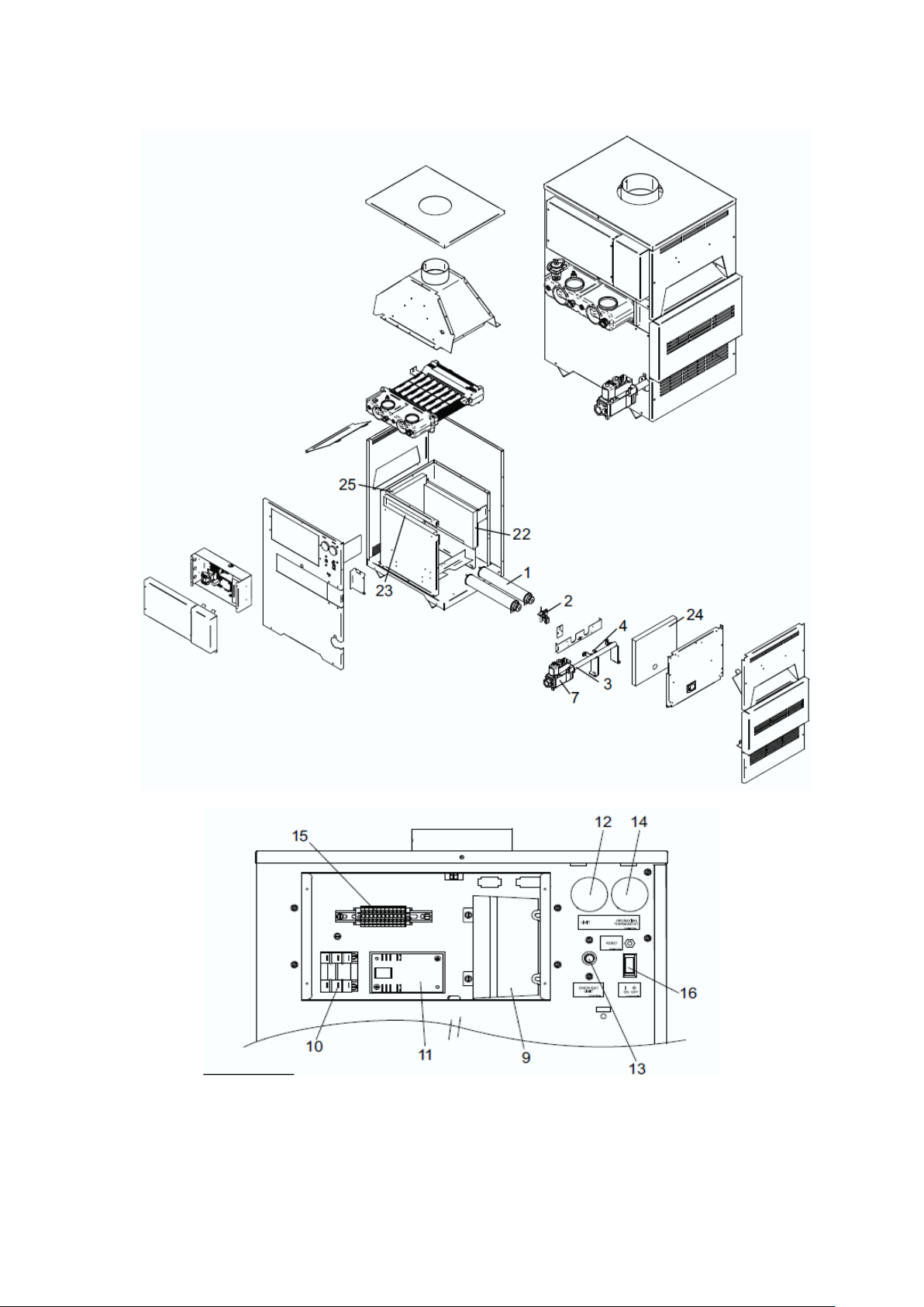
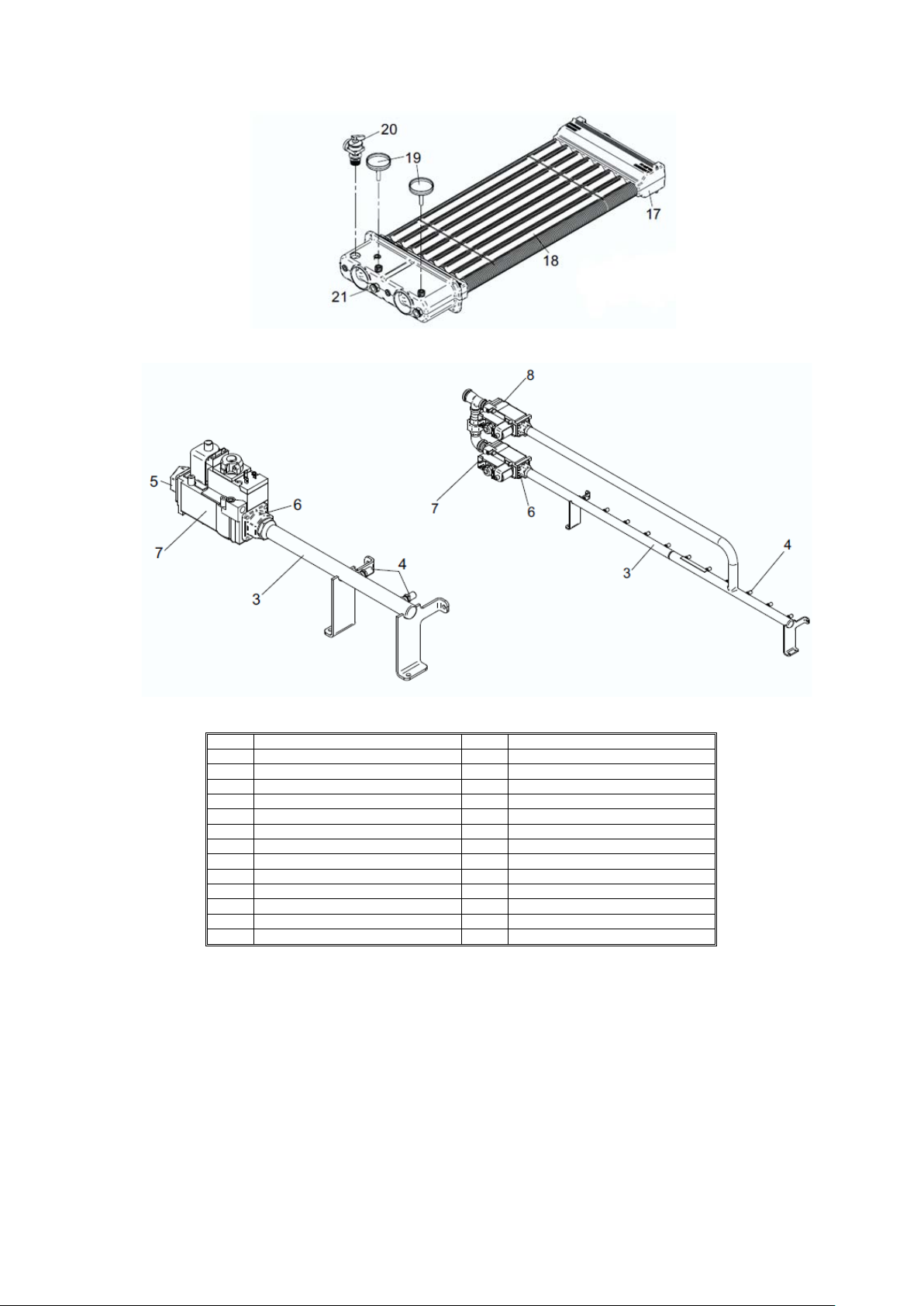
2.0 PRINCIPAL PARTS
FIGURE 2.1 EXPLODED DIAGRAM
FIGURE 2.2 EXPLODED DIAGRAM – CONTRO L PANEL ASSEMBLY
Page 6
6
FIGURE 2.3 EXPLODED DIAGRAM – HEAT EXCHANGER
ITEM
DESCRIPTION
ITEM
DESCRIPTION
1
Main burner bar
14
Control thermostat
2
Pilot burner assembly
15
Terminal str ip
3
Burner manifold
16
On/off switch
4
Main burner injector
17
Heat exchan ger
5
Gas inlet flange
18
‘V’ baffle
6
Manifold fla nge
19
Temperature gauge
7
Gas valve
20
Pressure/temperature relief valve
8
Gas valve
21
Bulbwell pocket
9
Sequence cont rol
22
Right side fi bre board
10
Relay
23
Left side fibre board
11
Time delay relay
24
Front fibre b oard
12
High limit thermostat
25
Rear fibre board
13
Overheat thermostat
FIGURE 2.4 EXPLODED DIAGRAM - GAS MANIFOLD ASSEMBLY
TABLE 2.1 REMOVABLE COMPONENTS
Page 7

7
3.0 TECHNICAL DATA
Model Number
MC91CE
MC136CE
MC181CE
MC226CE
MC271CE
MC316CE
MC361CE
MC401CE
MC501CE
GENERAL DATA
Input (gross) - kW
26.4
39.6
52.8
65.9
79.1
92.3
105.5
117.2
146.5
Input (net) - kW
23.8
35.6
47.0
59.4
71.3
83.1
95.1
105.6
132.0
Output - kW (80°/60°)
20.8
31.0
41.4
52.3
62.7
73.2
83.6
93.0
118.8
Recovery Rat e (44° ∆T) - l/hr
432
648
864
1044
1260
1476
1692
1872
2340
Recovery Rat e (50° ∆T) - l/hr
380
570
760
919
1109
1299
1489
1647
2059
Shipping Weight - kg
57
64
71
84
89
99
104
127
132
WATER DATA
Water content - litres
3
3.2
3.4
3.5
3.6
3.7
3.8
4.2
4.5
Water connections (F&R) –
“BSP
Max. Water Pr essure - bar
11
11
11
11
11
11
11
11
11
Min. Water Pressure - bar
0.5
0.5
0.5
0.5
0.5
0.5
0.5
0.5
0.5
Maximum water temperature
Maximum water temperature
(boilers) - °C
GAS DATA (G20)
Gas inlet connection – “BSP
¾”
¾”
¾”
¾”
¾”
¾”
¾”
¾”
1”
Gas Flow Rate - m3/hr
2.51
3.77
5.03
6.27
7.53
8.79
10.05
11.16
13.91
Burner Pressure - mbar
8.7
8.7
8.7
8.7
8.7
8.7
8.7
8.7
8.7
Minimum Gas Inlet Pressure mbar
Maximum Gas Inlet Pressure -
GAS DATA (G31)
Gas inlet connection – “BSP
¾”
¾”
¾”
¾”
¾”
¾”
¾”
¾”
1”
Gas Flow Rate - m3/hr
0.99
1.49
1.98
2.48
2.97
3.47
3.97
4.41
5.51
Burner Pressure - mbar
26.0
26.0
26.0
26.0
26.0
26.0
26.0
26.0
26.0
Minimum Gas Inlet Pressure mbar
Maximum Gas Inlet Pressure mbar
FLUE DATA
Flue spigot diameter - mm
126
152
178
178
200
200
228
250
250
Flue gas volume - m3/min
0.79
1.25
1.64
2.07
2.52
2.92
3.39
3.79
4.73
Maximum flue gas temp. - ⁰C
140
140
130
130
160
160
160
160
160
2 2 2 2 2 2 2 2 2
(water heaters) - °C
mbar
90 90
105 105 105 105 105 105 105 105 105
17.5 17.5 17.5 17.5 17.5 17.5 17.5 17.5 17.5
25 25 25 25 25 25 25 25 25
27 27 27 27 27 27 27 27 27
45 45 45 45 45 45 45 45 45
90 90 90 90 90 90 90
TABLE 3.1: TECHNICAL DATA
Page 8
8
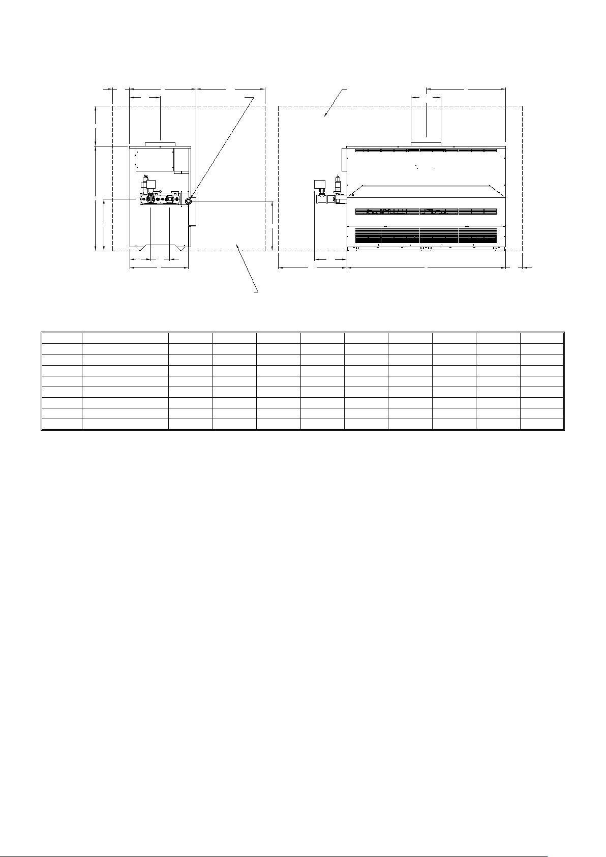
Dimension
Description
MC91CE
MC136CE
MC181CE
MC226CE
MC271CE
MC316CE
MC361CE
MC401CE
MC501CE
A
Overall height of heater
750
750
750
750
750
750
750
750
876
B
Overall width of heater
394
495
597
673
749
825
902
1130
1334
C
Overall depth of heater
546
546
546
546
546
546
546
559
559
D
Centreline of flue
197
248
298
337
375
413
451
565
667
E
Flue diameter
126
152
178
178
203
203
228
254
254
F
Height of ga s inlet
171
171
171
171
171
171
171
171
321
G
Centreline of gas inlet
475
475
475
475
475
475
475
475
493
H
Service clearance above
355
355
355
737
737
737
737
737
737
152
H
A
432
260
OUTLET
C
INLET
610
GAS CONNECTION
RECOMMENDED CLEARANCES
F
E DIA
D
178 159
G
(TO CENTRE OF GAS INLET)
RECOMMENDED CLEARANCES
263
610
FIGURE 3.1: DIMENSIONS
TABLE 3.1: DIMENSIONS
B
152
Page 9

9
4.0 GENER AL REQUIREMENTS
The Lochinvar Mini Copper-Fin has been designed to operate trouble free for many years. These instructions
should be followed closely to obtain the maximum usage and efficiency of the equipment. PLEASE read the
instructions fully before installing or using the appliance.
4.1 RELATED DOCUMENTS
It is law that all gas appliances are installed by competent persons, in accordance with The Gas Safety
(Installation and Use) Regulations 1998. Failure to install appliances correctly could lead to prosecution. It is in
your own interest, and that of safety, to ensure that this law is complied with.
The installation of the equipment MUST be in accordance with the relevant requirements of the Gas Safety
Regulations, Building Regulations, I.E.E. Regulations and the bylaws of the local water undertaking. The
installation should also be in accordance with any relevant requirements of the local gas distributor and local
authority.
In addition the installation should follow the relevant guidance offered in the following documents. It is not
practical to list all relevant information but emphasis is placed on the following documents, as failure to comply
with the guidance given will almost certainly result in an unsatisfactory installation:
BS EN 1858: 2003 Chimneys. Components. Concrete flue blocks
BS 5440-1: 2008 Installation and maintenance of flues and ventilation for gas appliances of rated input
not exceeding 70kW net (1st, 2nd and 3rd family gases)
Part 1: Specification for installation and maintenance of flues
BS 5440-2: 2009 Installation and maintenance of flues and ventilation for gas appliances of rated input
not exceeding 70kW net (1st, 2nd and 3rd family gases)
Part 2: Specification for installation and maintenance of ventilation for gas
appliances
BS 6644: 2005 Specification for Installation of g as fired hot water boilers of rated inputs between
70kW
nd
+ A1: 2008 (net) and 1.8MW (net) (2
and 3rd family gasses)
BS 6700: 1997 Design, installation, testing and maintenance of services supplying water for
domestic use within buildings and their curtilages
BS 6880: 1988 Code of practice for low temperature hot water systems of output greater than 45kW
Parts 1, 2 and 3
BS 7074: 1989 Application, selection and installation of expansion vessels and ancillary equipment
Parts 1and 2 for sealed systems
BS 7671: 2008 Requirements for electrical installations, I.E.E. wiring regulations seventeenth edition
CP 342: Code of practice for centralised hot water supply-buildings other than dwellings
Part 2 1974
IGE/UP/1: Installation pipework on industrial and commercial premises
Edition 2
IGE/UP/2: Gas installation pipework, boosters and compressors on industrial and commercial
Edition 2 premises
Page 10

10
IGE/UP/4: Commissioning of gas fired plant on industrial and commercial premises
Edition 2
IGE/UP/10: Installation of flued gas appliances in industrial and commercial premises
Edition 3
Gas Safety (Installation and Use) Regulations 1998 (England, Scotland & Wales)
CIBSE: Guide parts A, B and C
H.S.E. guidance Automatically controlled steam and hot water boilers
note PM5:
Third edition of the 1956 Clean Air Act Memorandum on Chimney Heights
Manufacturer's notes must not be taken in any way as overriding statutory obligations.
5.0 WATER QUALITY
Water supply quality may adversely affect the efficiency and performance of water heaters and hot water systems.
The situation can intensify where higher temperatures or demands exist.
Water hardness should not exceed 205ppm CaCO
and TDS (Total Dissolved Solids) of untreate d water should
3
not exceed 350ppm. If these values are exceeded, contact Lochinvar Limited for further guidance.
6.0 LOCATION
6.1 PLANT ROOM VENTILATION
The Lochinvar Mini Copper-Fin may only be installed in a room that complies with the appropriate ventilation
requirements. For further details, please refer to Section 9: AIR SUPPLY or to BS5440-2 or BS6644 as
appropriate.
6.2 GENERAL REQUIREMENTS
Corrosion of the heat exchanger and flue system may occur if air for combustion contains certain chemical
vapours. Such corrosion may result in poor combustion and create a risk of asphyxiation. Aerosol propellants,
cleaning solvents, refrigerator and air conditioning refrigerants, swimming pool chemicals, calcium and sodium
chloride, waxes and process chemicals are corrosive. Products of this sort should not be stored near the water
heater or outside by the air intake (if applicable). The fitting of this equipment in a situation where aerosols or
other chemicals may be entrained into the combustion air will invalidate the warranty.
The equipment must be installed on a level, non-combustible surface that is capable of adequately supporting its
weight (when filled with water) and any ancillary equipment. The operation of the equipment must not cause the
temperature of any combustible material in the vicinity of the equipment and its flue to exceed 65 °C. If such a
situation is unavoidable, appropriate insulation should be provided.
Locate the equipment so that if the appliance or any connecting pipework should leak, water damage will not
occur. When such locations cannot be avoided it is recommended that a suitable drain pan be installed under the
equipment. The pan should be adequately drained but must not restrict the combustion or ventilation airflow.
6.3 CLEARANCES
The location chosen for the equipment must permit the provision for a satisfactory flue system and an adequate air
supply. The location must also provide adequate space for servicing and air circulation around each unit. This
includes any electrical trunking laid across the floor and to the appliance.
See Figure 3.1 and Table 3.1 for dimensions and clearances. Further details regarding locations are given in
BS5440 or BS6644 as appropriate.
Page 11

11
7.0 GAS SU PPLY
The Lochinvar Mini Copper-Fin range is suitable for use on second and third family gasses 2H - G20 - 20mbar and
3P - G31 - 37mbar. Details relating to Natural Gas (2H) appear below; for details relating to Propane (3P)
please refer to Section 13: LPG FUEL.
7.1 SERVICE PIPES
The local gas distributor must be consulted at the installation planning stage in order to establish the availability of
an adequate supply of gas. An existing service pipe must not be used without prior consultation with the local gas
distributor.
7.2 METERS
A new gas meter will be connected to the service pipe by the local gas distributor contractor. An existing gas
meter should be checked, preferably by the gas distributor, to ensure that it is adequate to deal with the rate of gas
supply required.
7.3 GAS SUPPLY PIPES
Supply pipes must be fitted in accordance with IGE/UP/2. Pipework from the meter to the equipment must be of
adequate size. The complete installation must be purged and tested as described in IGE/UP/1. Refer to Section
13: LPG FUEL for information on LPG pipework installation guidance.
7.4 BOOSTED SUP PLIES
Where it is necessary to employ a gas pressure booster, the controls must include a low-pressure cut-off switch at
the booster inlet. The local gas distributor must be consulted before a gas pressure booster is fitted. For details of
how to connect a low-pressure cut-off switch, please refer to Section 11: ELECTRICAL SUPPLY.
7.5 PLANT-ROOM CONTROL VALVE
A manual valve for plant-room isolation must be fitted in the gas supply line. It must be clearly identified and
readily accessible for operation, preferably by an exit.
7.6 EQUIPMENT G AS SYSTEM LEAK CHECK
An approved isolating valve and union should be installed for each unit in a convenient and safe position
and be clearly marked. Ensure that the manual gas service valve is in the OFF position. Although the
equipment receives a gas leak check and gas train component integrity check prior to leaving the factory, transit
and installation may cause disturbance to unions, fittings and components. During commissioning a further test
for tightness should be carried out on the equipment gas pipework and components.
Care must be taken not to allow leak detection fluid on or near any electrical parts or connections.
Page 12

12
8.0 FLUE SYSTEM
8.1 FLUE SYSTEM GENERAL REQUIREMENTS
Detailed recommendations for the flue system are given in BS5440-1 for equipment of rated input not exceeding
70kW net, BS6644 for equipment above 70k W net and IGE/UP/10 for equipment of rated input above 54kW net.
The following notes are intended to give general guidance only.
8.2 FLUE SYSTEM S
Any flue termination must be in such a position as will not cause a hazard to the health of persons who may be
nearby or a nuisance to other persons beyond the curtilage. The flue terminal must be positioned externally such
as to allow the dispersal of products of combustion and air intake. The terminal should be installed in a location
where it will not easily flood or be blocked by snow.
The flue terminal position is very important and must be 1000mm above the roof surfaces or at least 600mm
above any parapet and clear of all adjacent obstructions. It must also be clear of any openable windows,
ventilators or entries that would let flue products from re-entering the building. Recommendations can be found in
BS6644 or BS5440 Part 1 as appropriate.
A minimum of 600mm of vertical flue directly above the draught diverter should be provided where possible on all
draught flue installations. If this dimension cannot be achieved please contact Lochinvar Limited for further
guidance. The weight of the flue must be adequately supported by securing clips and not by the appliance.
The flue system should be designed to maintain atmospheric pressure or a slight suction at the equipment flue
connection at all times within the range of 0.08 to 0.10 mbar (8 to 10 Pascals).
Due to the high thermal efficiency of the equipment, the flue gas temperature is approximately 130°C - 160°C.
Condensation in the flue is thus more likely to occur than with lower efficiency equipment. It is strongly
recommended that twin-wall or insulated flue pipe is used on all in sta llations . Care should be taken to ensure that
the flue is installed such that any condensation is continuously drained. All f lues should have a minimum slope of
2° upwards in the direction of the exhaust gas flow. All joints should be such that any condensat ion is directed
back down the slope to an open drain connection in the flue. The drain pipe must be manufactured from a
corrosion resistant material and be at least 15mm diameter. It must also have a fall of at least 2 to 3° (approx. 3-5
cm per metre) and connect to a drain via a waste trap.
8.3 FLUE MATERIALS – CONVENTI ONAL FLUE INSTALLATIONS
• Flue materials, including all jointing materials and fittings should be free from asbestos, durable,
resistant to corrosion and non-combustible.
• When passing up through or adjacent to combustible materials measures need to be taken to prevent
the temperature of the combustible material from exceeding 60°C. The flue must be at least 50mm from
any combustible material unless shielded by a non-combustible sleeve with an air gap of at least 25mm
• Flues shall be of a size not less than specified in Table 3.1. They should be fitted so there is no risk to
anybody in the building and no risk of accidental damage.
• If using an existing brick chimney, a suitable liner should be installed before connecting to the appliance.
The flue should take the shortest possible route and rise continuously to the terminal avoiding the use of
o
bends when there is a change in direction. Horizontal and very shallow runs of flue should be
90
avoided since they impede the flow of gases and increase local cooling.
Page 13

13
8.4 MULTIPLE FLUE INSTALLATION
High
(cm2)
Low
(cm2)
High
(cm2)
Low
(cm2)
MC91CE
23.8
26.4
106
132
264
264
528
MC181CE
• Common flues may be used on multiple installations only if all the heaters are of the same burner
system and fuel type and should be sized to ensure complete evacuation of the flue products from the
installation.
• Where one appliance is to be used more regularly or for longer periods than the others in the group, it
should be connected at the point nearest the main flue. Please refer to BS6644 for further information
and recommendations.
• A split collar should be fitted above the draught diverter so that the flue is secure but can be
disconnected for servicing. The weight of the flue must be adequately supported by securing clips and
not by the heater.
• If a 600mm vertical rise before connection to the common header is not possible, the common header
should be sized to ensure adequate evacuation of all products of combustion.
8.5 FAN DILUTION SYSTEMS
An alternative to a natural draught flue system is a Flue dilution system, which is suitable for connection to the Mini
Copper-Fin’s but must be properly designed by a specialist flue company.
8.6 BALANCED COMPARTMENTS
The equipment is suitable for siting within a balanced compartment. This compartment must be designed by a
specialist company.
9.0 AIR SUPPLY
The following information is based on single appliance installations only. If more than one appliance is being
used, BS5440-2 or BS6644 (as appropriate) should be consulted to calculate the necessary requirements.
This is a Type B
appliance and must be installed outside or in a room separated from inhabited rooms
11
with suitable ventilation directly to the outside.
9.1 NATURAL VENTILATION
The combustion air requirements are as follows:
Compartment Compartment
(Direct to Outside) (To Internal S pace)
Model
Gross
Input
(kW)
Net
Input
(kW)
Ventilation
(Room)
2
(cm
)
MC136CE 35.6 39.6 160 199 396 396 792
47.0 52.8 212 264 528 528 1056
MC226CE 59.4 65.9 264 330 659 659 1318
TABLE 9.1 COMBUSTION VENTILATION REQUIREMENTS MC91CE – MC226CE
Page 14

14
Low
Summer Use
Medium
Summer Use
High
Summer Use
Low
Summer Use
Medium
Summer Use
High
Summer Use
High
(cm2)
Low
(cm2)
High
(cm2)
Low
(cm2)
High
(cm2)
Low
(cm2)
High
(cm2)
Low
(cm2)
High
(cm2)
Low
(cm2)
High
(cm2)
Low
(cm2)
MC271CE
79.1
71.3
143
286
214
357
286
428
357
713
428
785
500
856
MC361CE
105.5
95.1
190
380
285
475
380
570
475
951
570
1045
665
1140
MC501CE
Flow rate per kW total rated net input (m3/h)
Minimum Inlet Air
Difference between Inlet and Ext ract Air
With draught diverters
2.80
2.07 ± 0.18
Without draught diverters.
Heat input (net):
=
95.1 kW
Minimum combustion air flow rate:
=
95.1 x 2.8 m3/h
=
266.28 m3/h
Ventilation grille size (high level):
=
192 cm2
Plant Room Enclosure
Input
(kW)
Net
Input
(kW)
Model
Gross
MC316CE 92.3 83.1 167 333 250 416 333 500 416 831 500 916 583 999
MC401CE 117.2 105.6 212 423 317 528 423 634 528 1056 634 1162 740 1268
146.5 132.0 264 528 396 660 528 792 660 1320 792 1452 924 1584
TABLE 9.2 COMBUSTION VENTILATION REQUIREMENTS MC271CE – MC501CE
9.2 MECHANICAL VENTILATION
To comply with the relevant installation standards, (BS5440-2:2009 for appliances with net heat inputs below
70kW and BS6644:2005 for appliances with net heat inputs between 70kW and 1.8MW) combustion ventilation
must be provided for all open flued appliances. In situations where this cannot be provided by the means of
ventilation grilles, combustion air can be supplied by a fan. The minimum flow rate for the fan should be in
accordance with Table 9.3.
If required, extract air can also be through the use of a fan. When sizing the extract fan, the extract flow rate
should be calculated by subtracting the difference volume (from Table 9.3) from the actual supplied volume of inlet
air. If therefore, a larger than required inlet volume is provided, the extract flow rate will need to be increased
accordingly.
If the ventilation discharge from the plant room is through the means of simple openings relying on thermal effects,
the minimum free areas of the openings and any associated grilles should be as specified for natural ventilation
(see separate “Free Area Requirements – Combustion” specification sheet). The ventilation openings shall be at
high level and the air supply shall be at low level.
Ventilation must not be provided through natural inlet and mechanical extract as this will cause a negative
pressure within the plant room and may lead to the products of combustion being drawn into the plant room.
When using mechanical ventilation systems, an automatic control should be used to cause a safety shut-down of
the burner in the event of failure of air-flow either inlet or extract ducts.
NOTE: VENTILATION MUST NOT BE PROVIDED THROUGH NATURAL INLET AND
MECHANICAL EXTRACT AS THIS WILL CAU SE A NEGATIVE PRESSURE WITHIN TH E PLANT ROOM AND
MAY LEAD TO THE PRODUCTS OF COMBUSTION BEING DRAWN INTO THE PLANT ROOM.
Appliance Type
(with or without draught stabilisers)
TABLE 9.3 MECHANICAL VENTILATION FLOW RATES
Worked Example – Mechanical inlet/natural discharge:
Lochinvar MC361CE
(Combustion, Ventilation)
2.60 1.35 ± 0.18
(Inlet minus Extract Ventilation)
Page 15

15
Worked Example – Mechanical inlet/mechanical discharge (minimum combustion air flow rate):
Heat input (net):
=
95.1 kW
Minimum combustion air flow rate:
=
95.1 x 2.8 m3/h
=
266.28 m3/h
Difference between inlet and extract air
(maximum value):
=
95.1 x (2.07 + 0.18) m3/h
=
213.98 m3/h
Difference between inlet and extract air
(minimum value):
=
95.1 x (2.07 - 0.18) m3/h
=
179.74 m3/h
Extract air (maximum value):
=
266.28 m3/h – 179.74 m3/h
=
86.54 m3/h
Extract air (minimum value):
=
266.28 m3/h – 213.98 m3/h
=
52.30 m3/h
Heat input (net):
=
95.1 kW
Minimum combustion air flow rate:
=
95.1 x 2.8 m3/h
=
266.28 m3/h
Actual combustion air flow rate:
=
95.1 x 3.15 m3/h
=
299.57 m3/h
Difference between inlet and extract air:
(maximum value)
=
95.1 x (2.07 + 0.18) m3/h
=
213.98 m3/h
Difference between inlet and extract air:
(minimum value)
=
95.1 x (2.07 - 0.18) m3/h
=
179.74 m3/h
Extract air (maximum value):
=
299.57 m3/h – 179.74 m3/h
=
119.83 m3/h
Extract air (minimum value):
=
299.57 m3/h – 213.98 m3/h
=
85.59 m3/h
Lochinvar MC361CE
Worked Example – Mechanical inlet/mechanical discharge (alternate combustion air flow rate):
Lochinvar MC361CE
Page 16

16
10.0 WATER CONNECTIONS
10.1 WATER HEATERS
10.1.1 GENERAL
Mini Copper-Fin water heaters require a minimum flow rate and should also be supplied with separate storage
vessels. Suitably sized pumps and separate storage vessels are available from Lochinvar Limited as ancillary
options.
Note: Lochinvar Limited recommends the use of glanded bronze pumps.
Recommended pipework layouts are available for different water heater and storage vessel combinations. Please
contact Lochinvar Limited for details. When multiple units are connected using common pipework, it is
recommended that a reverse-return arrangement is used to ensure equal flow through each unit.
The requirements of minimum water flow are given in Table 10.2. Recommendations for the water circulation
system are given in BS6644 and CP 342. The following notes are of particular importance.
1. When the unit is being utilised as a direct-fired water heater it is designed for use with a direct type
storage vessel. Contact Lochinvar Limited for help in sizing the storage vessel
2. Circulating pipework not forming part of the useful heating surface should be insulated. Cisterns,
expansion vessels and pipework situated in areas exposed to freezing conditions should also be
insulated.
3. Drain valves must be located in accessible positions that will permit draining of the entire system
including the unit and the storage vessel.
4. Tapping sizes for connection to the water system are detailed in Table 3.1.
5. Ideally, individual valves should be fitted to each unit to enable isolation from the system. The
arrangement must comply with the requirements of BS6644.
6. Every system should be provided with a water gauge complete with isolating valve so that the pressure
of the system may be displayed for commissioning and maintenance purposes.
10.1.2 OPEN VENTED SYSTEM ARRANGEMENT
The Lochinvar Mini Copper-Fin can be used in an open vented arrangement provided that a vent pipe in
accordance with CP342, BS6644 or BS6700 as appropriate is fitted. T he minimum static head requ irement for an
open vented system is 0.5 bar.
10.1.3 UNVENTED SYSTEM ARRANGEMENT
NOTE: IT IS STRONGLY RECOMMENDED THAT UNVENTED HOT WATER SYSTEMS BE
INSTALLED BY AN APPROVED INSTALLER.
If the Lochinvar Mini Copper-Fin is to be used in an unvented arrangement, the system should follow the guidance
given in BS6700 and must comply with The Building Regulations: Part G3. A kit of components that have been
suitably sized for the unvented operation of the appliance is available from Lochinvar Limited. For further
information, contact Lochinvar Limited.
10.1.4 WATER PRESSURE GAUG E
Every system should be provided with a gauge complete with isolating valve so that the pressure of the system
may be displayed for commissioning and maintenance purposes.
10.1.5 DRAIN VALVES
Each unit should be provided with a 15mm drain valve fitted into the return to enable the heat exchanger to be
drained without draining the entire system.
Page 17

17
10.1.6 EXPANSION VESSEL SIZ IN G
Stored
C
Stored
C
The following information is based on an inlet pressure of 3.5 bar. If a different inlet pr essure is to be used, please
consult BS6700.
S V * e
V V =
0.45
Where:
V V = Vessel Volume
S V = System Volume
e = Coefficient of Expansion (See Table 10.1)
Temp.
°
e 0.005 0.006 0.008 0.010 0.012 0.015 0.017
Temp.
°
e 0.020 0.023 0.026 0.030 0.031 0.033 0.037
30 35 40 45 50 55 60
65 70 75 80 82 85 90
TABLE 10.1 COEFFICIENT OF EXPANSION OF WATER AT 3.5 BAR INLET PRESSURE
10.1.7 DE-STRATIFICATION
If the hot water system does not include a constantly circulated building return, it is recommended that a destratification pump be fitted, between the flow connection and the circulation connection on the right hand side of
the storage vessel, to ensure an even temperature distribution throughout the stored water. De-stratification pump
kits are available as ancillary items; please contact Lochinvar Limited for details.
10.1.8 CIRCULATING PUMPS
In order to ensure the correct flow rates through the water heater, the unit requires a bronze glanded pump sized
to overcome the resistance of the heat exchanger and a primary pipework loop. The primary loop should be no
longer than 14 metres plus the following fittings:
6 x 90° Elbows
2 x Unions
2 x Full bore lever ball valves
2 x Tee fittings (cold feed & HWS return)
For longer distances or a greater number of fittings, the pump may have to be resized.
The specification of this type of pump ensures that the bronze body and associated parts in contact with water are
suitable for potable use. A "glanded" construction is required to ensure that any scale in the system does not build
up within the pump and cause a resistance that can lead to a loss of water flow. Glandless (canned rotor) pumps
are not recommended by Lochinvar Limited due to the fact that in hard water areas, scale can build up within the
rotor and failure can occur, not only of the pump but also the heater itself. The warranty will be void if a failure of
the heat exchanger occurs due to a "glandless" pump.
Page 18

18
Total System P ressure
Loss - Metre H20
2.44
2.44
2.44
2.44
2.44
2.44
2.44
2.44
Model Differential - K Flow – l/s
MCW91CE 3 1.9 2.44
MCW136CE 4 1.9
MCW181CE 5 1.9
MCW226CE 6 1.9
MCW271CE 8 1.9
MCW316CE 9 1.9
MCW361CE 11 1.9
MCW401CE 12 1.9
MCW501CE 15 1.9
TABLE 10.2 WATER HEATER FLOW RATES
To ensure proper velocity through the heat exchanger, it is necessary to balance the temperature rise across the
heat exchanger from inlet to outlet. Excessive scale build up in th e tubes is a result of too little velocity; excessive
pitting or erosion on the inside of the tubes is caused by too much velocity. Care should be taken to measure the
temperature rise and maintain a constant velocity as follows:
1. Thermometers are installed on the inlet and outlet of the equipment to measure water temperature
entering and leaving.
2. The pump should run continuously.
3. With the pump in operation and the burner “off”, both thermometers should read the same temperature.
4. Switch the burner on and allow the temperature to stabilise. Record the difference between the inlet and
outlet temperature. The difference will be the “temperature rise”.
5. Compare the temperature rise with the required figure shown in Table 10.2.
A. If the temperature rise is too high, water velocity is too low. Check the following:
1. No restrictions in the outlet of the heater.
2. All valves are open between the heater and the storage vessel.
3. Pump is running in the proper direction.
4. Pump size is correct.
5. Pipework size is correct.
B. If the temperature rise is too low, water velocity is too high. Adjust accordingly.
1. Throttle the valve on the outlet side of the heater, until temperature rise is steady and at correct
value shown in Table 10.2.
2. Periodically check the temperature rise to ensure proper operation.
10.1.9 PIPEWORK SIZE
The pipework for the primary circulating loop should be in accordance with the following table. If more than one
water heater is to be connected to common circulating pipework, the common sections need to be sized in
accordance with the following table:
1 x MCW 2 x MCW 3 x MCW
Pipe Size 54mm 67mm 76mm
TABLE 10.3 PIPE SIZES
Page 19

19
10.2 HEATING BOILERS
10.2.1 GENERAL
The Mini Copper-Fin boiler requires a minimum water flow rate through the heat exchanger. A suitably sized
primary circulating pump is available from Lochinvar Limited as an ancillary option.
Recommended pipework layouts are available; please contact Lochinvar Limited for details. When multiple units
are connected using common pipework, it is recommended that a reverse-return arrangement is used to ensure
equal flow through each unit.
The requirements of minimum water flow are given in Table 10.4. Recommendations for the water circulation
system are given in BS6644 and CP 342. The following notes are of particular importance.
1. Circulating pipework not forming part of the useful heating surface should be insulated. Cisterns,
expansion vessels and pipework situated in areas exposed to freezing conditions should also be
insulated.
2. When the unit is being utilised as a combined central heating and domestic hot water boiler the hot water
vessel must be of the indirect type.
3. Drain valves must be located in accessible positions that will permit draining of the entire system
including the unit.
4. Tapping sizes for connection to the heating system are detailed in Table 3.1.
5. Ideally, individual valves should be fitted to each unit to enable isolation from the system. The
arrangement must comply with the requirements of BS6644.
6. Every system should be provided with a water gauge complete with isolating valve so that the pressure
of the system may be displayed for commissioning and maintenance purposes.
10.2.2 OPEN VENTED SYSTEM ARRANGEMENT
The Lochinvar Mini Copper-Fin can be used in an open vented arrangement provided that a vent pipe in
accordance with CP342 or BS6644 as appropriate is fitted. The minimum static head requirement for an open
vented system is 0.5 bar.
10.2.3 SEALED SYSTEM ARRANGEMENT
If a sealed system arrangement is required, a suitable pressurisation unit is available from Lochinvar Limited on
request. Sealed systems should incorporate a safety valve with a lift pressure no greater than the maximum
pressure rating of any component in the heating system. The maximum working pressure of the boiler is 11.0 bar.
A suitably sized expansion vessel should also be fitted to the system.
10.2.4 DRAIN VALVES
Each unit should be provided with a 15mm drain valve fitted into the return to enable the heat exchanger to be
drained without draining the entire system.
Page 20

20
10.2.5 EXPANSION VESSEL SIZ IN G
Total System P ressure
MCB91CE
20
0.12
0.06
MCB136CE
20
0.20
0.06
MCB181CE
20
0.24
0.06
MCB226CE
20
0.36
0.09
MCB271CE
20
0.48
0.12
MCB316CE
20
0.58
0.12
MCB361CE
20
0.70
0.15
MCB401CE
20
0.85
0.40
MCB501CE
20
0.97
0.46
The following information is based on a static head of 35 metres and a cold fill pressure of 3.8 bar:
S V * e
V V =
0.45
Where:
V V = Vessel Volume
S V = System Volume
e = Coefficient of Expansion (See Table 10.1)
10.2.6 PRIMARY CIRCULATING PUMPS
The Lochinvar Mini Copper-Fin boiler may need a primary pump to ensure correct flow through the boiler and a
secondary pump to circulate water around the heating system. Pump selection must ensure that the flow rate
through the unit is in accordance with that stated in Table 10.4. The pump should be sited to facilitate servicing. It
is important that the existing pump size is checked when the boiler is being used for a refurbishment project, to
ensure that the minimum flow rate can be achieved.
Model Differential - K Flow – l/s
Loss - Metre H20
TABLE 10.4 SYSTEM HEAD LOSS
Primary circulating pumps are available as ancillary items; please contact Lochinvar Limited for details
FIGURE 10.1 BOILER PRIMARY/SECONDARY ARRANGEMENT
Page 21

21
10.3 POOL HEATING
rmal Supply
MC91CE
19 W
MC136CE
19 W
MC181CE
19 W
MC226CE
19 W
MC271CE
19 W
MC316CE
19 W
MC361CE
19 W
MC401CE
19 W
MC501CE
38 W
The Mini Copper-Fin is also suitable for directly heating pool water without a secondary heat exchanger. The
design of the interconnecting pipework must incorporate a bypass to ensure that the return water temperature
does not remain below 50°C for long periods of time. This b ypass arrangement is also needed for low system
temperature circuits. Contact Lochinvar Limited for further information
10.4 FLOW SWITCH
The Lochinvar Mini Copper-Fin range of equipment is based on a low water content copper heat exchanger. In
order to ensure a long life expectancy it is important that the burner does not fire if the main circu lating pump fails.
This is more important in the water heater specification due to the fact that in hard water areas if the heater fires
up without adequate water flow, then lime scale will be deposited in a very short space of time and will cause nonwarrantable failure. In both boilers and water heaters it is detrimental to the heater to be fired without adequate
water flow, as localised over-heating will occur.
In order to overcome this problem the units are supplied complete with a flow switch to ensure that the heater will
not fire unless the pump is operational. It should be noted that the flow switch is not an accurate flow-measuring
device and only proves that the pump is operational.
11.0 ELECTRICAL SUPPLY
Wiring external to the equipment must be installed in accordance with the I.E.E. Regulations and any local
regulations that apply.
Model
No
Voltage
230V AC
50 Hz
1 PH
External Fuse
Rating
6.0 A
Power Consumption
TABLE 11.1 ELECTRICAL SUPPLY REQUIREMENTS
WARNING: THIS APPLIANCE MUST BE EARTHED
A suitably competent person MUST check wiring. Normal supply required is 230 volts AC, single phase,
50 Hz. An isolator with a contact separation of at least 3mm in all poles should be sited close to the
equipment and must only serve that equipment. The double pole switch must be readily ac cessible und er
all conditions.
Page 22

22
11.1 ELECTRICAL CONNECTIONS
Access to the electrical connections is achieved by taking off the removable panel next to the controls positioned
on the left hand side of the equipment. Connections to the equipment should pass through one of the 20mm
knock out wiring gland covers provided.
FIGURE 11.1 CONTROL PANEL
11.2 EXTERNAL CONTROLS
The circulating pump should have a separate power source with a suitably sized overload protection device.
The power supply to the Mini Copper-Fin should not be switched by a time clock; the equipment has a remote
stop/start circuit across terminals R and W. Any safety interlocks should be wired in series with the integral flow
switch across terminals X and B. Power is supplied from the equipment for these functions and will be the same
as the equipment’s power supply.
Volt free terminals for a fault alarm condition are marked VFA. Additionally the equipment puts a 230 volt signal
on to the brown wire in the ALM terminal when in a fault condition; the blue wire in the ALM terminal can be used
for a neutral.
Volt free terminals for burner on indication are marked RUN.
11.3 ARC WELDING PRECAUTIONS
The appliance must be isolated from the mains electricity supply in the event of electric arc welding being carried
out on any interconnecting pipework.
Page 23

11.4 WIRING DIAGRAM
1
2
3
4
5
12
11
10
13
14
16
C 1 221C
21 3
L
N
R
W
X
B
C
VFA
VFA
ALM
ALM
RUN
RUN
5
2
1
3
6
4
1
BL
BR/W
BK/W BK
BK
W
OR
BK
W
OR
R
BR
R
W
G
OR
R
RBRBLY/GR
Y/GR
Y/GR
BR
BR
BL
BL
BR
BR
BL
BL
BL
R
R
OR
OR
BR
BL
I O
NOC
8
+
-
72
63
54
+
-
1
2
3
4 5
6
7
8
10
9
11
12
1 TERMINAL STRIP
2 ROCKER SWITCH
TTB DEVICE6
FLAME FAILURE RESET7
8 IGNITION SEQUENCE CONTROLLER
12 FAULT RELAY (TIME DELAY)
11 RUN RELAY
9 PILOT ASSY.
GAS VALVE10
OVERHEAT LIMIT RESET3
OPERATING THERMOSTAT5
4 LIMIT THERMOSTAT
FIGURE 11.2 WIRING DIAGRAM MC91CE – MC401CE
Page 24

24
1
2
3
4
5
12
11
10
13
14
16
C 1 2
21C
21 3
L
N
R1
W1
X
B
C
VFA
VFA
ALM
ALM
RUN
RUN
BL
BR
BK/W BK
W
OR
BK
W
OR
R
BR
R
W
G
OR
BR
RBRBLY/GR
Y/GR
Y/GR
BR/W
BR
BL
BR
BR
BL
BL
BL
R
R
OR
OR
I O
NOC
R2
W2
R/BK Y/GR BL
Y/GR
BL
BK
R/BK
R/BK
R/BK
BK
BL
BK
11
-
+
BL
4
6
3
1
2
5
1 8
+
-
72
63
54
12
54
3
2
1
7
6
8
9
10
LIMIT THERMOSTAT4
5 OPERATING THERMOSTAT
3 OVERHEAT LIMIT RESET
10 GAS VALVES
PILOT ASSY.9
RUN RELAY11
FAULT RELAY (TIME DELAY)12
IGNITION SEQUENCE CONTROLLER8
7 FLAME FAILURE RESET
6 TTB DEVICE
ROCKER SWITCH2
TERMINAL STRIP
1
10
BR
FIGURE 11.3 WIRING DIAGRAM MC501CE
Page 25

12.0 COMMISSIONING AND TESTING
12.1 ELECTRICAL INSTALLATION
Notes on the requirements for electrical installation are provided in Section 11: ELECTRICAL SUPPLY.
Schematic drawings of the control circuit are shown in Figure 11.2 and 11.3.
12.2 GAS INSTALLATION
For design see Section 7: GAS SUPPLY. See Figure 3.1 for details on the position of the gas connection.
12.3 WATER CONNECTIONS
For design see Section 10: WATER CONNECTIONS
The system should be thoroughly flushed out with cold water without any circulating pump in position.
Ensure all the valves are open.
If a secondary pump is to be fitted, it should be fitted before the system is filled and air locks cleared. Check the
system for leaks and repair as necessary. If the system is configured in an unvented arrangement, check the
expansion vessel cushion pressure.
12.4 COMMISSIONING THE EQUIPMENT
12.4.1 GENERAL CHECKS PRIOR TO LIGHTING
A person deemed competent MUST be responsible for the commissioning of this equipment. Before
attempting to commission any equipment, ensure that personnel involved are aware of what action is
about to be taken and begin by making the following checks:
1. Flueway passages to chimney are clear.
2. Adequate ventilation exists in the plant room.
3. The system is fully charged with water, ready to receive heat. All necessary valves are open and the
secondary pump (if fitted) is circulating water.
4. The gas supply pipework is clear of any loose matter, tested for soundness and purged.
5. Any condensate drain fitted to the flue system is installed correctly and the condensate trap is filled with
water.
NOTE: If a condensate trap is not filled before use, products of combustion may escape and can lea d t o
severe personal injury or death
12.4.2 EQUIPMENT CHECKS PRIOR TO LIGHTING
This unit has been designed for a nominal gas inlet pressure of 20 mbar when used on natural gas.
Information relating to propane firing can be found in Section 13: LPG FUEL.
1. Gas supply is connected but turned to the “off” position. Any unions or fittings are correctly tightened,
test points are closed and the flame rectification probe lead is connected correctly. Ensure the ceramic
sheath around the flame rectification probe is not cracked or broken.
2. Ensure electricity supply is connected.
3. Check that the circulating pumps are fully bled.
4. Remove the temperature overheat limit switch bulb from the pocket and by carefully applying a heat
source to the bulb the reset pin should operate. If satisfactory cool the bulb, reset the thermostat and
refit the bulb in its pocket.
5. Check that the combustion products discharge safety device (TTB) is correctly fitted to the appliance
draught diverter.
Page 26

26
12.4.3 PROCEDURE FOR INITIAL LIGHTING
IF THE UNIT IS T O OPERATE ON LPG REFER TO SECTION 13: LPG FUEL BEFORE PROCEEDING
1. Ensure that the gas inlet appliance isolating valve, provided by the installer, is in the ‘off’ position.
2. Remove the control cover (located above the water flow and return header). Set the thermostat to a
temperature above that of the system water.
3. Press the power rocker switch located below the thermostat dials to bring the equipment on.
4. The burner should try to fire and a spark should be visible by looking at the pilot assembly. As the gas
inlet appliance isolating valve is closed, the controls should go to a flame failure condition.
5. If the above occurs correctly, open the gas inlet appliance isolating valve and press the flame failure
reset button, positioned above the rocker switch.
6. After a short delay, the pilot should ignite and the main gas valve should energise lighting the main
burners.
NOTE: During initial warm-up, condensation may drop onto the burners. This will continue until the system
water reaches a temperature above 50°C.
7. Allow the system to reach temperature to check operation of the control thermostat.
8. Once the thermostat has been satisfied, check that the main burner and pilot burner flames have
extinguished.
12.4.4 GAS PRESSURE ADJUSTMENT AND COMBUSTION CHECKS
1. After the burner has operated for approximately 10 minutes, switch off the equipment.
2. Open the pressure test point on the inlet side of the gas valve, attach a manometer and check the
standing gas-inlet pressure.
3. Relight the appliance and check the operating gas-inlet pressure
NOTE: The equipment has been designed to conform to the requirements of the Gas Appliance (Safety)
Regulations (1992). For Natural Gas the gas pressure governor control system is configured for a
nominal gas inlet pressure of 20 mbar, with a maximum inlet pressure of 25 mbar. Information relating
to propane firing can be found in Section 13: LPG FUEL.
4. Switch off the appliance, remove manometer and close pressure test point.
5. Open the pressure test point on the outlet side of the gas valve and attach a manometer.
6. Relight the appliance and check the burner pressure.
7. If required, the burner pressure can be corrected by removing the dust cap with a large slotted
screwdriver and the adjusting screw turned clockwise to increase burner pressure or counter-clockwise
to decrease burner pressure. Details of the correct burner pressure can be found in Table 3.1
NOTE: A second gas control valve is fitted to the MC501CE model, this must also be adjusted in accordance
with the procedure taken for the first valve. Remember to shut all test points after removing the
manometer.
NOTE: If the dust cap is removed, once reinstalled it should be marked with an anti-tamper indicator.
8. Carry out a spillage test in accordance with BS5440-1.
9. Carry out a combustion analysis. Record all readings for future reference on a relevant
commissioning sheet.
Page 27

27
12.5 WATER HEATER TEMPERATURE ADJUSTMENT PROCEDURE
The temperature selector knob of the operator thermostat will be adjusted to its lowest setting when dispatched
from the factory. The operating thermostat setting should be adjusted to ensure that the water is stored at 60°C
and distributed at 50°C within 1 (one) minute at all outlets. Care is needed to avoid much higher temperatures
because of the risk of scalding. At 50°C the risk of scalding is small for most people, but the risk increases rapidly
with higher temperatures and for longer exposure times. The risk to young children and to those with a sensory or
mobility loss will be greater. Where a significant scalding risk has been identified, the use of thermostatic mixing
valves on baths and showers should be considered to reduce temperature, these need to be placed as close to
the point of use as possible.
The operating temperature of the water heater can be adjusted as follows:
1. Locate the control cover and remove.
2. Adjust the dial on the operating thermostat to give the desired water temperature.
3. Adjust the limit thermostat to 10°C above the operating thermostat setting.
4. Re-fit the control cover.
12.6 BOILER TEMPERATURE ADJUSTMENT PROCEDURE
The operating temperature of the boiler can be adjusted as follows:
1. Locate the control cover and remove.
2. Adjust the dial on the operating thermostat to give the desired water temperature.
3. Adjust the limit thermostat to 10°C above the operating thermostat setting.
4. Re-fit the control cover.
12.7 INSTALLATION NOISE
If care has been taken to follow the manufacturer’s instructions there should be no discernible noise from the
equipment. The allied pump motor may have a level of sound that could lead to consideration for acoustic
insulation, but care must be taken not to impede ventilation or airflow to the pump motor.
13.0 LPG FUEL NOTE! IT IS STRONGLY RECO MM ENDED THAT, ON LPG I NST ALL ATIONS, GA S DET ECTIO N EQUI PME NT
IS FITTED. THI S EQUI PMENT SHOULD BE POSI TIONE D NEA R THE APPL IANC E AND AT LOW LE VEL. I T
IS ALSO IMPORTANT THAT THE SPACE HOUSING TH E APPLIANCE IS ADEQUATELY VENTILATED AT
HIGH AND LOW LEVEL. THIS APPLI ANCE MUST NOT BE LOCATED BELOW GROUND E.G. IN A CELLAR
13.1 RELATED DOCUMENTS
In addition to those documents listed in Section 4.1: RELATED DOCUMENTS within the main body of the
installer’s guide the gas installation should also comply with the guidance offered in the following documents.
BS 5482-1: 2005 Code of practice for domestic butane and propane gas burning installations.
Part 1: Installations at permanent dwellings, residential park homes and commercial
premises, with installation pipework sizes not exceeding dn25 for steel and dn28 for
corrugated stainless steel or copper.
rd
The operation of the Mini Copper-Fin range on LPG-Propane (3
Family) 3P is similar to that on Natural Gas (2nd
Family) 2H and the design and installation details described in the main body of the installer’s guide should be
followed.
Page 28

28
13.2 PROPANE INJ ECTORS
Injector
Size
Marking
Pilot Burner
n/a
2304
Main Burner
2.0mm
2402
When converting to propane, the pilot and main burner injectors should be checked to ensure that they are
correctly sized. For further information, please refer to Table 13.1.
TABLE 13.1 LPG INJECTOR SIZES
13.3 CONVERSION TO LPG
This process must be carried out in the order stated. Failure to follow the following procedure may lead to
non-warrantable damage to the water heater. The conversion MUST be carried out be a competent person
certified for work on LPG fuel.
1. Turn power and gas off.
2. Remove middle and lower door panels.
3. Remove pilot assembly and fit LPG pilot orifice (ORF2614).
4. Remove the Natural Gas burner injectors and fit LPG injectors (ORF2402).
5. Re-fit middle and lower door panels.
6. Attach the LPG warning label and rating plate overlay.
13.4 LPG COMMISSIONING AND TESTING
The commissioning procedure on LPG is similar to that when the heater is firing on Natural Gas. Please refer to
Section 12.0 COMMISSIONING AND TESTING.
14.0 MAINTENANCE
14.1 GENERAL
KEEP APPLIANCE AREA CLEAR AND FREE FROM COMBUSTIBLE MATERIALS AND FLAMMABLE
VAPOURS AND LIQUIDS.
A competent person should check and ensure that the flue system, ventilation to the plant room, safety valve,
drain, pressure gauge etc. are in a serviceable and working condition and still comply with the relevant standards
and codes of practice, as detailed in Section 4: GENERAL REQUIREMENTS.
Servicing is recommended at intervals no greater than 12 months, preferably by a Lochinvar appointed person, to
ensure trouble free operation. Even if a tank maintenance schedule is determined to be less than annually, it is
important that all controls and safety features are checked for correct operation on an annual basis.
Measuring flue gas CO
and flue gas temperatures will give an indication of the state of the flue and burner.
2
Results of the flue gas analysis should be compared with previously measured values to establish possible loss of
efficiency.
Page 29

29
14.2 MAINTENANCE SCHEDULE
Equipment installed in a dusty or dirty contaminated atmosphere may require maintaining more frequently than on
an annual basis. When installed in a dusty or dirty environment, the combustion system should be checked at 3
month intervals to then determine the maintenance period required. Non-combustible particular matter such as
dust can block the ports of the burners and cause non-warrantable failures.
14.2.1 ADDITIONAL REQUIREMENTS FOR WATER HEATERS
Waterborne impurities consist of the particles of soil and sand, which can settle out and form a layer of sediment
on the bottom of the allied storage vessel. The amount of calcium carbonate (scale) released from water is in
direct proportion to water temperature and usage. The higher the water temperature or water usage, the more
scale deposits are dropped out of the water.
Scale accumu lation not only reduces the life of the equipment but also reduces efficiency of the water heater and
increases fuel consumption. The usage of water softening equipment greatly reduces the hardness of the water.
However, this equipment does not always remove all of the hardness (scale). For this reason it is recommended
that a regular schedule of de-scaling be maintained.
14.3 DRAINING THE WATER SYSTEM
The appliance must be drained if it is to be shut down and exposed to freezing temperatures. Maintenance and
service procedures may also require draining the appliance.
1. Turn off the electrical disconnect switch.
2. Connect a hose to the drain valve.
3. Locate hose’s discharge in an area where hot water will not cause any damage or injury.
4. Close the cold water inlet valve to system.
5. Open the system drain valve.
6. Open any installed vent point in the system to allow the system to drain.
7. If the appliance is being drained for an extended shutdown, it is s uggested the drain valve be left open
during this period.
14.4 WATER HEATER SERVICING
14.4.1 REMOVING SCALE AND SEDIMENT FROM THE ST OR A GE V ES SEL
1. Drain the water system. Refer to Section 14.3 DRAINING THE WATER SYSTEM.
2. Remove outer cover plate from lower side of storage vessel jacket.
3. Remove cover and gasket from cleanout opening.
4. Remove scale or sediment using care not to damage the enamel lining.
5. Check the distribution tube for scale build up and clean as necessary.
6. Inspect cleanout plate gasket and replace if necessary.
7. Install gasket and cleanout plate. Draw plate up square by tightening screws evenly.
14.4.2 SACRIFICIAL MAGNESIUM ANODES
If the Correx non-sacrificial anode protection system is used, there is no requirement to check the
condition of the anodes.
be inspected at least once a year.
The sacrificial magnesium anodes
must
Page 30

30
Enamel lined storage vessels are protected against corrosion by sacrificial anodes. The rate at whi ch the anodes
are depleted is dependent on the quality of the water, therefore it is important that the anodes are inspected as
follows:
1. Drain the water system. Refer to Section 14.3: DRAINING WATER SYSTEM.
2. Remove the plastic covers to expose the anode retaining plugs.
3. Remove the anodes and check their condition.
NOTE: If the anodes have reduced in size by more than 40% at any point along their length or if they are
severely pitted, new anodes should be fitted. Where the anodes are covered with particles they
should be cleaned. For reference, when new, the anode has a diameter of 21mm.
4. Reassembly procedure is the reverse of removal, ensuring all water joints are sealed using an
appropriate jointing compound.
NOTE: Where a water softener is used, the conditioned water may reduce the serviceable life of the tank.
The condition of the anodes must therefore be checked more frequently.
14.5 CLEANING THE HEAT EXCHANGER
1. Remove the gas valve cover panel by lifting it from its resting place and tip forward. This gains access
to gas valve(s) and the upper gas train.
2. Remove the self-tapping screws from the bottom grille panel and pull forward, taking care not to snag
the pilot tube, and remove.
3. Remove the self-tapping screws from the front draught diverter baffle and pull forward to remove.
4. Using a Pozi-Drive screwdriver, remove the wiring harness from the gas valve(s). Undo the pilot tube
from the gas valve using a 11mm spanner and move aside.
5. Using an 8mm socket, remove the gas train.
6. Remove the self-tapping screws from the upper front panel, pull forward and down slightly to detach the
panel. This now gains access to the rear of the control box (thermostat and internal wiring).
7. Cut through the cable ties securing the ionisation and spark cables (coloured white and orange
respectively) taking care not to damage the insulation of any secured wires. Disconnect the ionisation
and spark cables from ignition module pins 13 and 16 and pull cables through to the pilot assembly,
taking care not to strip any insulation on bare metal parts.
8. Remove the self-tapping screws from the insulation panel (with slight glass aperture) and remove the
panel. Remove the remaining self-tapping screws from the unpainted louvered fascia panel and pull
forward to access the burners and heat exchanger underside. (Note: This panel is backed with fibre
board; care must be taken to avoid damage.)
9. Having now gained access to the burner rack, lift and pull out the burner bars and clean each bar using
a suitable brush ensuring that the burner ports are clear of any obstructions and that there are no major
cracks in the outer wall. Should any burner bar be in sub-standard condition, a replacement should be
fitted.
10. Using a Pozi-Drive screwdriver undo retaining screws from the rear of the pilot assembly bracket and
carefully with draw the complete pilot assembly forward and from underneath the burner rack.
11. With the pilot assembly removed, check that there are no signs of damage to the spark or ionisation
probes and cables. If any damage is evident, the complete pilot assembly must be replaced. Check that
the pilot injector is free from debris.
12. To access heat exchanger baffles, the front inner draught diverter fascia must be removed. Undo the
self-tapping screws on the lower left and right sides of the flue hood and pull out the front under-fascia.
13. Unclip the v-baffles and remove each from the heater. Clean using a suitable brush replacing any
baffles that are in a poor condition.
14. Check the condition of the fibre board lining of the combustion chamber replacing any significant
damaged sections.
15. Using a suitable brush, clean all traces of soot and debris from the heat exchanger, taking care not to
damage the copper fins.
Page 31

31
16. Check the condition of the copper tubes to ensure each tube has not warped or annealed. If there are
any signs of damage to the heat exchanger it should be replaced.
17. If it is necessary to replace the heat exchanger, undo the self-tapping screws on the outer casing
adjacent to the header to open up the withdrawal opening. Remove the 8mm self-tapping screws from
the cast header. Take out the thermostat phials from pockets, noting their locations and move aside.
The heat exchanger can now be pulled forward (keeping it straight and parallel) to remove it from the
heater body.
18. Fit a replacement heat exchanger into the channels inside heater and push back until the cast headers
hit the stops. Fit a new sealing gasket to the water connection header and secure using the appropriate
self-tapping screws.
To reassemble the heater, sections 1-13 of the above procedure should be carried out in reverse.
To access the ignition module, terminal strip and fault relay PCB the self-tapping screws must be undone on
the large Left hand cover at the header end.
To access the thermostat dials and reset buttons, the thumb screw under the smaller right hand cover at
header end should be aligned with the slot in the cover and the cover be pulled forward and down.
Tools required:
No 2 Pozi-Drive screwdriver
Battery drill and socket driver
5/16” or 8mm spanner or socket
¼” or 6mm spanner or socket
7/16” or 11mm spanner
Leak detection spray
Gas approved jointing paste
Cable/wire cutters
Stiff bristle brush
14.6 REFILLING TH E SYSTEM
1. Close the drain valve.
2. Open any installed vent point to allow air to escape.
3. Open the cold water inlet valve and allow the system to fill.
4. Follow the lighting instructions as detailed in Section 12.4.3: PROCEDURE FOR INITIAL
LIGHTING.
5. Check for water leakage.
Page 32

32
14.7 OTHER CHECKS
MINI COPPER-FIN SE RIE S FAU LT FIN D ING GUI DE
Situation
Corrective Action
No Power
Check circuit breaker /Fuses
Equipment wi ll not start ignition sequence
Check that the pilot flame has extinguished.
Flame failur e
Pilot assembly or electrodes dirty or eroded.
Check faulty ignition sequence controller.
Short cycling of burners
Check that temperature differential across heat exchanger is
Improper cross-lighting of burners
Check for low main burner gas pressure.
Check burner injectors are aligned correctly.
Flue gas spillage
Check Flueways in heat exchanger are clear.
Check that flue is sized correctly.
14.7.1 RELIEF VALVES
At least once a year, the temperature and pressure relief valve and safety valve should be checked to ensure that
they are in operating condition. To check each valve, lift the lever or turn the screw cap at the end of the valve
several times. The valve should operate freely and seat properly.
If water does not flow, remove and inspect for obstructions or corrosion. Replace with a new valve of the
recommended size as necessary.
14.7.2 FLUE SYSTEM
Examine the exhaust and ventilation system at least once a year. Points of inspection are as follows:
1. Check for obstructions and/or deterioration of flue piping and terminal. Replace immediately where
needed.
2. Check the terminal for any foreign material and remove as necessary.
3. Check all flue system connections for leakage and re-seal as required.
4. Check for sufficient flue draught.
5. Check that ventilation grilles comply with current regulations.
14.8 TTB DEVICE
There is a thermostat that detects a down-draught situation in the flue. This is an auto-reset thermostat but, the
cause of activation must be investigated and remedial work carried out before allowing the equipment to operate
again. This device shall not be put out of operation due to the seriousness of untimely interference.
If required, this device should only be replaced with a genuine Lochinvar part.
14.9 FAULT FINDING
Check power is available at terminals R & W.
Check power i s available at terminals X & B.
Check setting of all three thermostats.
Check power is available at terminal 1 of the sequence
controller.
Check that flame failure reset button has been pushed.
Pilot assembly insulation on cables cracked/broken.
Pilot assembly electrodes bent out of position.
Check for low gas pressure.
correct.
Check for low inlet supply gas pressure.
Check for excessive flue draught.
Check ventilation requirements.
Check that flue is clear.
Page 33

33
15.0 USER INSTRUCTIONS
Once the installation and commissioning is complete, the equipment owner or their representative should be made
aware of the lighting and operating instructions. A practical demonstration should be given describing each
functional step. Incorrect use may result in injury and will also invalidate the warranty. The installers guide should
be handed over and kept in a safe place for easy reference. It is strongly recommended that the users read and
understand the separate User Instructions.
Page 34

34
NOTES
NOTES
__________________________________________________________________________________
__________________________________________________________________________________
__________________________________________________________________________________
__________________________________________________________________________________
__________________________________________________________________________________
__________________________________________________________________________________
__________________________________________________________________________________
__________________________________________________________________________________
__________________________________________________________________________________
__________________________________________________________________________________
__________________________________________________________________________________
__________________________________________________________________________________
__________________________________________________________________________________
__________________________________________________________________________________
__________________________________________________________________________________
__________________________________________________________________________________
__________________________________________________________________________________
__________________________________________________________________________________
__________________________________________________________________________________
__________________________________________________________________________________
__________________________________________________________________________________
__________________________________________________________________________________
__________________________________________________________________________________
__________________________________________________________________________________
__________________________________________________________________________________
__________________________________________________________________________________
__________________________________________________________________________________
__________________________________________________________________________________
__________________________________________________________________________________
__________________________________________________________________________________
Page 35

35
NOTES
NOTES
__________________________________________________________________________________
__________________________________________________________________________________
__________________________________________________________________________________
__________________________________________________________________________________
__________________________________________________________________________________
__________________________________________________________________________________
__________________________________________________________________________________
__________________________________________________________________________________
__________________________________________________________________________________
__________________________________________________________________________________
__________________________________________________________________________________
__________________________________________________________________________________
__________________________________________________________________________________
__________________________________________________________________________________
__________________________________________________________________________________
__________________________________________________________________________________
__________________________________________________________________________________
__________________________________________________________________________________
__________________________________________________________________________________
__________________________________________________________________________________
__________________________________________________________________________________
__________________________________________________________________________________
__________________________________________________________________________________
__________________________________________________________________________________
__________________________________________________________________________________
__________________________________________________________________________________
__________________________________________________________________________________
__________________________________________________________________________________
__________________________________________________________________________________
__________________________________________________________________________________
Page 36

36
 Loading...