

Lochinvar LTN07575, LTN10075, LTL07575ST, LTN10075ST, LTL10075ST Instruction Manual
...
Instruction Manual
Low Lead Content
RESIDENTIAL GAS WATER HEATERS
NOT FOR USE IN MANUFACTURED (MOBILE) HOMES
INSTALLATION - OPERATION
- SERVICE - MAINTENANCE
WARNING: If the information in these
instructions is not followed exactly, a fire
or explosion may result causing property
damage, personal injury or death.
Do not store or use gasoline or other
flammable vapors and liquids in the
vicinity of this or any other appliance.
WHAT TO DO IF YOU SMELL GAS:
Do not try to light any appliance.
•
Do not touch any electrical switch; do
•
not use any phone in your building.
Immediately call your gas supplier
•
from a neighbor’s phone. Follow the
gas supplier’s instructions.
If you cannot reach your gas supplier,
•
call the fire department.
Installation and service must be
performed by a qualified installer,
service agency or the gas supplier.
Read and understand this instruction
manual and the safety messages
herein before installing, operating or
servicing this water heater.
Failure to follow these instructions and
safety messages could result in death
or serious injury.
This manual must remain with the
water heater.
• For Your Safety •
AN ODORANT IS ADDED TO THE GAS USED
BY THIS WATER HEATER.
PRINTED 0517 100286991_2000538798_Rev C
PLACE THESE INSTRUCTIONS ADJACENT TO HEATER AND NOTIFY OWNER TO KEEP FOR FUTURE REFERENCE.
KEEP THIS MANUAL IN THE POCKET ON HEATER FOR FUTURE REFERENCE
WHENEVER MAINTENANCE ADJUSTMENT OR SERVICE IS REQUIRED.
1

TABLE OF CONTENTS
SAFE INSTALLATION, USE AND SERVICE..................3
APPROVALS ..................................................................3
GENERAL SAFETY INFORMATION ..............................4
INTRODUCTION ............................................................5
Abbreviations Used ................................................... 5
Qualied Installer or Service Agency ......................... 5
Preparing for The Installation .................................... 5
TYPICAL INSTALLATION ...............................................6
GET TO KNOW YOUR WATER HEATER - GAS
MODELS ................................................................... 6
Application/Use of Water Heater ...............................7
HOTTER WATER CAN SCALD ................................. 7
Facts to Consider About the Location ........................8
High Altitude ..............................................................9
Adjusting Air Shutter for Higher Altitudes ................... 9
Clearances ............................................................... 10
Insulation Blankets ................................................... 11
Hard Water ............................................................... 11
Outdoor Air Through Two Vertical Ducts ................... 18
Air From Other Indoor Spaces .................................. 18
Venting ...................................................................... 19
Gas Piping ................................................................ 21
Sediment Traps ........................................................22
TEMPERATURE REGULATION ..................................24
Start-Up Conditions .................................................. 25
FOR YOUR INFORMATION .........................................25
Operational Conditions ............................................. 26
PERIODIC MAINTENANCE .........................................27
Venting System Inspection .......................................27
Burner Inspection ..................................................... 27
Burner Cleaning ........................................................ 27
Air Shutter Adjustment .............................................. 28
Housekeeping ........................................................... 28
Anode Rod Inspection .............................................. 28
Temperature-Pressure Relief Valve Test .................. 28
Draining and Flushing ............................................... 30
INSTALLATION REQUIREMENTS ..............................12
Gas Supply Systems ................................................ 12
Gas Pressure Requirements ................................... 12
Supply Gas Regulator .............................................. 12
Mixing Valves ............................................................ 13
Water Piping .............................................................13
Temperature-Pressure Relief Valve .......................... 14
Filling the Water Heater ............................................ 15
Air Requirements ...................................................... 16
Unconned Space .................................................... 16
Conned Space ........................................................ 16
Fresh Air Openings For Conned Spaces ................ 17
Outdoor Air Through Two Openings .........................17
Outdoor Air Through One Opening ........................... 17
Outdoor Air Through Two Horizontal Ducts ..............18
LEAKAGE TEST POINTS ............................................31
Service ...................................................................... 31
Removing and Replacing the Gas Control Valve/
Thermostat .............................................................. 32
2

SAFE INSTALLATION, USE AND SERVICE
Low Lead Content
The proper installation, use and servicing of this water heater is extremely important to your safety and the safety of
others.
Many safety-related messages and instructions have been provided in this manual and on your own water heater to
warn you and others of a potential injury hazard. Read and obey all safety messages and instructions throughout this
manual. It is very important that the meaning of each safety message is understood by you and others who install,
use, or service this water heater.
This is the safety alert symbol. It is used to alert you to
potential personal injury hazards. Obey all safety
messages that follow this symbol to avoid possible
injury or death.
DANGER indicates an imminently
DANGER
WARNING
hazardous situation which, if not avoided,
will result in injury or death.
WARNING indicates a potentially hazardous
situation which, if not avoided, could result
in injury or death.
CAUTION indicates a potentially hazardous
CAUTION
CAUTION
All safety messages will generally tell you about the type of hazard, what can happen if you do not follow the safety
message, and how to avoid the risk of injury.
situation which, if not avoided, could result in
minor or moderate injury.
CAUTION used without the safety alert
symbol indicates a potentially hazardous
situation which, if not avoided, could result in
property damage.
APPROVALS
3
GENERAL SAFETY INFORMATION
Una instalación, uso o servicio técnico inadecuados
pueden
generar daños a la propiedad.
PRECAUCIÓN
•
No haga funcionar el calentador de agua si alguna parte ha
quedado expuesta a inundaciones o daños por el agua.
•
Inspeccione las varillas del ánodo de manera regular y
reemplácelas si están gastadas de manera significativa.
•
Instale en un lugar con drenaje.
•
Llene el tanque con agua antes de ponerlo en funcionamiento.
•
Se necesitan tanques de expansión térmica correctamente
dimensionados en todos los sistemas de agua.
Consulte este manual para la instalación y el mantenimiento.
4

INTRODUCTION
Thank You for purchasing this water heater. Properly
installed and maintained, it should give you years of
trouble free service.
ABBREVIATIONS USED
Abbreviations Found In This Instruction Manual:
• UL - Underwriters Laboratories Inc.
• ANSI - American National Standards Institute
• NFPA - National Fire Protection Association
• ASME - American Society of Mechanical Engineers
• AHRI - Air-Conditioning, Heating and Refrigeration
Institute
• CAN - Canada
• EPACT - Energy Policy Act
• CSA - Canadian Standards Association
This gas-red water heater is design certied by
Underwriters Laboratories Inc. under the American
National Standard/CSA Standard for Gas Water Heaters
ANSI Z21.10.3 • CSA 4.3
(current edition).
QUALIFIED INSTALLER OR SERVICE AGENCY
Installation and service of this water heater requires
ability equivalent to that of a Qualied Agency (as dened
by ANSI below) in the eld involved. Installation skills
such as plumbing, air supply, venting, gas supply and
electrical supply are required in addition to electrical
testing skills when performing service.
ANSI Z223.1 2006 Sec. 3.3.83: “Qualied Agency” - “Any
individual, rm, corporation or company that either in
person or through a representative is engaged in and is
responsible for (a) the installation, testing or replacement
of gas piping or (b) the connection, installation, testing,
repair or servicing of appliances and equipment; that
is experienced in such work; that is familiar with all
precautions required; and that has complied with all the
requirements of the authority having jurisdiction.”
If you are not qualied (as dened by ANSI above) and
licensed or certied as required by the authority having
jurisdiction to perform a given task do not attempt to
perform any of the procedures described in this manual.
If you do not understand the instructions given in this
manual do not attempt to perform any procedures
outlined in this manual.
PREPARING FOR THE INSTALLATION
1. Read the “General Safety” section, page 4 of this
manual rst and then the entire manual carefully. If you
don’t follow the safety rules, the water heater will not
operate properly. It could cause DEATH, SERIOUS
BODILY INJURY AND/OR PROPERTY DAMAGE.
This manual contains instructions for the installation,
operation, and maintenance of the gas-red water
heater. It also contains warnings throughout the manual
that you must read and be aware of. All warnings and
all instructions are essential to the proper operation of
the water heater and your safety. Since we cannot put
everything on the rst few pages, READ THE ENTIRE
MANUAL BEFORE ATTEMPTING TO INSTALL OR
OPERATE THE WATER HEATER.
2. The installation must conform with these instructions
and the local code authority having jurisdiction. In
the absence of local codes, the installation must
comply with the National Fire Protection Association, 1
Batterymarch Park, Quincy, MA 02269.
3. If after reading this manual you have any questions or
do not understand any portion of the instructions, call
the local gas utility or the manufacturer whose name
appears on the rating plate.
4. Carefully plan the place where you are going to put
the water heater. Correct combustion, vent action, and
vent pipe installation are very important in preventing
death from possible carbon monoxide poisoning and
res, see Figure 9 (page 10) and Figure 10 (page
14).
Examine the location to ensure the water heater is
consistent with the requirements described in Facts to
Consider About the Location
5. For California installation this water heater must be
braced, anchored, or strapped to avoid falling or
moving during an earthquake. See instructions for
correct installation procedures. Instructions may be
obtained from California Ofce of the State Architect,
400 P Street, Sacramento, CA 95814.
6. Massachusetts Code requires this water heater to be
installed in accordance with Massachusetts 248-CMR
2.00: State Plumbing Code,
(page 8).
and 248-CMR 5.00.
5
IGNITER
WIRE
RED WIRE
(LEFT SIDE)
PILOT
TUBE
MANIFOLD TUBE
IGNITER
BUTTON
IGNITER
LEAD
WIRE
WHITE
WIRE
(RIGHT
SIDE)
GAS CONTROL/
TEMPERATURE KNOB
VAC
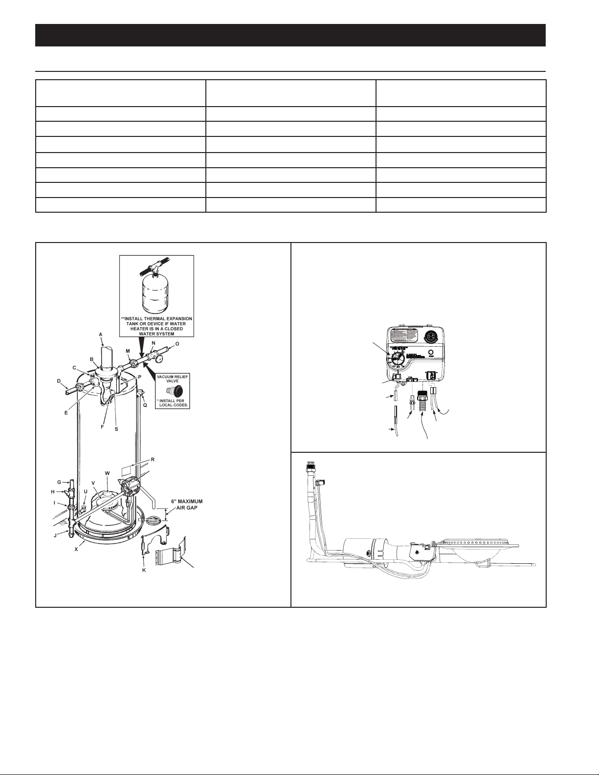
TYPICAL INSTALLATION
T
L
GET TO KNOW YOUR WATER HEATER - GAS MODELS
A. Vent Pipe I. Ground Joint Union Q. Temperature-Pressure Relief
Valve
B. Draft Hood J. Sediment Trap R. Rating Plate
C. Anode K. Inner Door S. Flue Bafe(s)
D. Hot Water Outlet L. Outer Door T. Gas Control Valve/Thermostat
E. Outlet M. Union U. Drain Valve
F. Insulation N. Inlet Water Shut-off Valve V. Pilot and Main Burner
G. Gas Supply O. Cold Water Inlet W. Flue
H. Manual Gas Shut-off Valve P. Inlet Dip Tube X. Metal Drain Pan
• INSTALL IN ACCORDANCE WITH LOCAL CODES.
• SEDIMENT TRAP AS REQUIRED BY LOCAL
CODES.
• ALL PIPING MATERIALS TO BE SUPPLIED BY
CUSTOMERS.
**CLOSED WATER SYSTEMS ARE THOSE WITH BACK FLOW PREVENTION DEVICES INSTALLED IN THE
WATER SERVICE LINE.
FIGURE 1. TYPICAL INSTALLATION
6
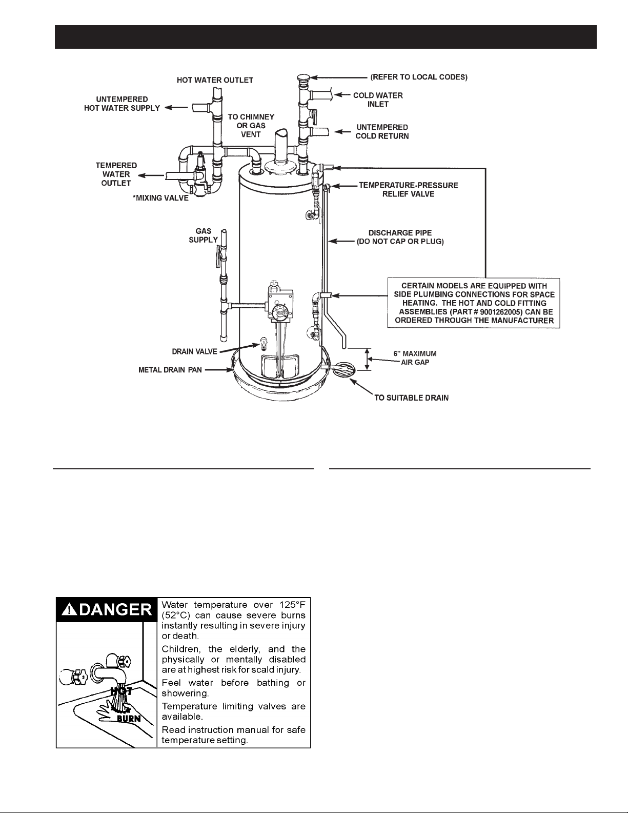
TYPICAL INSTALLATION
FIGURE 2. MIXING VALVE USAGE
APPLICATION/USE OF WATER HEATER
This Water Heater has been design certied as
complying with ANSI Z21.10.3-CSA 4.3 current edition for
water heaters and is considered suitable for:
• Water (Potable) Heating and Space Heating*: All
models are considered suitable for water (potable)
heating and space heating.
*These water heaters cannot be used in space heating
applications only.
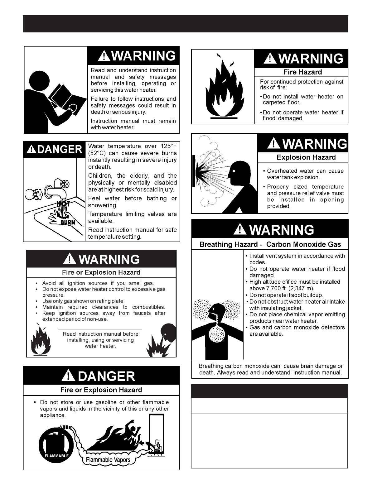
HOTTER WATER CAN SCALD
Water heaters are intended to produce hot water.
Water heated to a temperature which will satisfy space
heating, clothes washing, dish washing, and other
sanitizing needs can scald and permanently injure
you upon contact. Some people are more likely to be
permanently injured by hot water than others. These
include the elderly, children, the inrm, or physically/
mentally handicapped. If anyone using hot water in your
home ts into one of these groups or if there is a local
code requiring a certain temperature water at the hot
water tap, then you must take special precautions. In
addition to using the lowest possible temperature setting
that satises your hot water needs, a means such as
a *Mixing Valve should be used at the hot water taps
used by these people or at the water heater. See Figure
2
(page 7). Mixing valves are available at plumbing
supply or hardware stores. Consult a qualied installer
or service agency. Follow mixing valve manufacturer’s
instructions for installation of valves. Before changing
the factory setting on the thermostat, see Temperature
Regulation
(page 24).
7
TYPICAL INSTALLATION
FACTS TO CONSIDER ABOUT THE LOCATION
Carefully choose an indoor location for the new water
heater, because the placement is a very important
consideration for the safety of the occupants in the
building and for the most economical use of the water
heater. This water heater is not for use in manufactured
(mobile) homes or outdoor installation.
Whether replacing an old water heater or putting the
water heater in a new location, the following critical points
must be observed:
1. Select a location indoors as close as practical to the
gas vent or chimney to which the water heater vent
is going to be connected, and as centralized with the
water piping system as possible.
2. Selected location must provide adequate clearances
for servicing and proper operation of the water heater.
• Sensors mounted in the drain pan that trigger an
alarm or turn off the incoming water to the water
heater when leakage is detected.
• Sensors mounted in the drain pan that turn off the
water supply to the entire home when water is
detected in the drain pan.
• Water supply shut-off devices that activate based on
the water pressure differential between the cold water
and hot water pipes connected to the water heater.
• Devices that will turn off the gas supply to a gas water
heater while at the same time shutting off its water
supply.
Installation of water heater must be accomplished in
such a manner that if the tank or any connections should
leak, ow will not cause damage to the structure. For
this reason, it is not advisable to install water heater in
an attic or upper oor. When such locations cannot be
avoided, a suitable metal drain pan should be installed
under the water heater. Metal Drain pans are available
at your local hardware store. Such a metal drain pan
must have a minimum length and width of at least 2” (51
mm) greater than water heater dimensions and must be
piped to an adequate drain. The pan must not restrict
combustion air ow.
Water heater life depends upon water quality, water
pressure and the environment in which the water heater
is installed. Water heaters are sometimes installed in
locations where leakage may result in property damage,
even with the use of a drain pan piped to a drain.
However, unanticipated damage can be reduced or
prevented by a leak detector or water shut-off device
used in conjunction with a piped drain pan. These
devices are available from some plumbing supply
wholesalers and retailers, and detect and react to
leakage in various ways:
INSTALLATIONS IN AREAS WHERE FLAMMABLE
LIQUIDS (VAPORS) ARE LIKELY TO BE PRESENT OR
STORED (GARAGES, STORAGE AND UTILITY AREAS,
ETC.): Flammable liquids (such as gasoline, solvents,
propane [LP or butane, etc.] and other substances such
as adhesives, etc.) emit ammable vapors which can be
ignited by a gas water heater’s pilot light or main burner.
8
The resulting ashback and re can cause death or
serious burns to anyone in the area, as well as property
damage. If installation in such areas is your only option,
then installation must be accomplished in a way that
the pilot ame and main burner ame are elevated from
oor at least 18 inches. While this may reduce chances
of ammable vapors, from a oor spill being ignited,
gasoline and other ammable substances should never
be stored or used in the same room or area containing a
gas water heater or other open ame or spark producing
appliance.
NOTE: Flammable vapors may be drawn by air currents
from other areas of the structure to the appliance.
Also, the water heater must be located and/or protected
so it is not subject to physical damage by a moving
vehicle.
Water heaters covered in this manual have been tested
and approved for installation at elevations up to 7,700
feet (2,347 m) above sea level. For installation above
7,700 feet (2,347 m), the water heater’s Btu input should
be reduced at the rate of 4 percent for each 1,000 feet
(305 m) above sea level which requires replacement of
the burner orice in accordance with the National Fuel
Gas Code ANSI Z223.1/NFPA 54. Contact your local gas
supplier for further information.
Failure to replace the standard orice with the proper
high altitude orice when installed at elevations above
7,700 feet (2,347 m) could result in improper and
inefcient operation of the water heater, producing carbon
monoxide gas in excess of the safe limits. This could
result in serious injury or death. Contact your local gas
supplier for any specic changes that may be required in
your area.
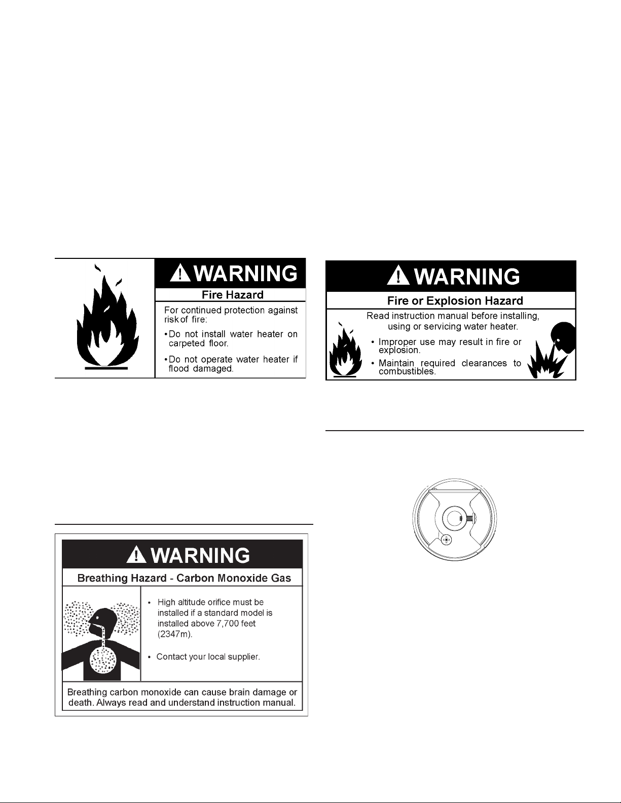
This water heater must not be installed directly on
carpeting. Carpeting must be protected by metal or wood
panel beneath the water heater extending beyond the full
width and depth of the water heater by at least 3” (76.2
mm) in any direction, or if the water heater is installed in
an alcove or closet, the entire oor must be covered by
the panel. Failure to heed this warning may result in a re
hazard.
HIGH ALTITUDE
ADJUSTING AIR SHUTTER FOR HIGHER ALTITUDES
The air shutter is preset with the air shutter in the open
position and for most applications changing the air
shutter is not required.
FIGURE 3. AIR SHUTTER OPEN
A correctly set burner should have a stable quiet ame.
The ame will be blue with a well dened blue inner
ame, Some yellow tipping is normal with LP gas. See
Figure 4.
9
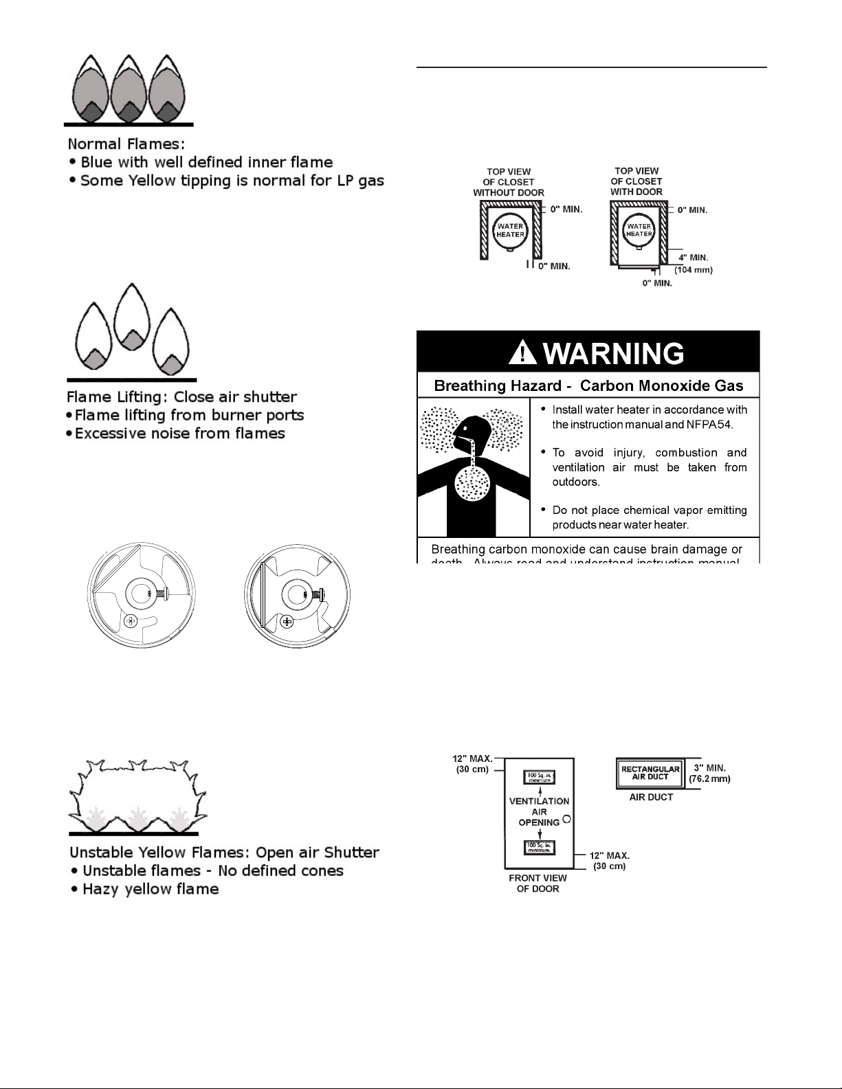
FIGURE 4. NORMAL FLAMES
If ames are seen to lift from the burner ports, gradually
close the air shutter until a stable ame is achieved. See
Figure 5.
CLEARANCES
Minimum clearances between the water heater and
combustible construction are 0 inch at the sides and rear,
4” (102 mm) at the front, and 6” (153 mm) from the vent
pipe. Clearance from the top of the jacket is 12” (305
mm).
FIGURE 8. CLEARANCES
FIGURE 5. FLAME LIFTING
See Figure 6 for the appearance of the half-closed and
full-closed air shutter. Normally, this ame lifting occurs
only at altitudes above 5,400 feet.
FIGURE 6. HALF-CLOSED AND CLOSED AIR SHUTTER
If the air shutter is closed too far, the ame will look hazy
and not have dened cones. See the example in Figure
7
(page 10). In this case, the air shutter will need to be
opened. See Figure 3.
A gas water heater cannot operate properly without the
correct amount of air for combustion. Do not install in a
conned area such as a closet, unless you provide air
as described in Air Requirements (page 16). Never
obstruct the ow of ventilation air. If you have any doubts
or questions at all, call your gas supplier. Failure to
provide the proper amount of combustion air can result in
a re or explosion and cause death, serious bodily injury,
or property damage.
FIGURE 7. UNSTABLE FLAME
FIGURE 9. VENTILATION CLEARANCES
10
If this water heater will be used in beauty shops, barber
shops, cleaning establishments, or self-service laundries
with dry cleaning equipment, it is imperative that the
water heater or water heaters be installed so that
combustion and ventilation air be taken from outside
these areas.
Propellants of aerosol sprays and volatile compounds,
(cleaners, chlorine based chemicals, refrigerants, etc.)
in addition to being highly ammable in many cases, will
also change to corrosive hydrochloric acid when exposed
to the combustion products of the water heater. The
results can be hazardous, and also cause product failure.
INSULATION BLANKETS
Breathing Hazard - Carbon Monoxide Gas
Do not obstruct water heater air intake
with insulating blanket.
Gas and carbon monoxide detectors
are available.
Install water heater in accordance with
the instruction manual.
Breathing carbon monoxide can cause brain damage or
death. Always read and understand instruction manual.
Should you choose to apply an insulation blanket to this
heater, you should follow these instructions. See Leakage
Test Points
(page 31) for identication of components
mentioned below. Failure to follow these instructions
can restrict the air ow required for proper combustion,
potentially resulting in re, asphyxiation, serious personal
injury or death.
• DO NOT apply insulation to the top of the water
heater, as this will interfere with safe operation of the
draft hood. See Figure 16 (page 20).
• DO NOT cover the thermostat or the temperature-
pressure relief valve.
• DO NOT allow the insulation to come within 2 inches
(5 cm) of the oor to prevent blockage of combustion
air ow to the burner.
• DO NOT cover the instruction manual. Keep it on the
side of the water heater or nearby for future reference.
• DO obtain new warning and instruction labels from
the manufacturer for placement on the blanket directly
over the existing labels.
• DO inspect the insulation blanket frequently to make
certain it does not sag, thereby obstructing the
combustion air ow.
HARD WATER
Insulation blankets are available to the general public for
external use on gas water heaters but are not necessary
with these products. The purpose of an insulation blanket
is to reduce the standby heat loss encountered with
storage tank heaters. The water heaters covered by this
manual meet or exceed the Energy Policy Act standards
with respect to insulation and standby heat loss
requirements, making an insulation blanket unnecessary.
Where hard water conditions exist, water softening or the
threshold type of water treatment is recommended. This
will protect the dishwashers, coffee urns, water heaters,
water piping and other equipment.
11

INSTALLATION REQUIREMENTS
GAS SUPPLY SYSTEMS
Low pressure building gas supply systems are dened
as those systems that cannot under any circumstances
exceed 14” W.C. (1/2 PSI Gauge). These systems do
not require pressure regulation. Measurements should
be taken to insure that gas pressures are stable and fall
within the requirements stated on the water heater rating
plate. Readings should be taken with all gas burning
equipment off (static pressure) and with all gas burning
equipment running at maximum rate (dynamic pressure).
The gas supply pressure must be stable within 1.5”
W.C. from static to dynamic pressure to provide good
performance. Pressure drops that exceed 1.5” W.C.
may cause rough starting, noisy combustion or nuisance
outages. Increases or spikes in static pressure during
off cycles may cause failure to ignite or in severe cases
damage to appliance gas valves. If your low pressure
system does not meet these requirements, the installer is
responsible for the corrections.
High Pressure building supply systems use pressures
that exceed 14” W.C. (1/2 PSI Gauge). These systems
must use eld supplied regulators to lower the gas
pressure to less than 14” W.C. (1/2 PSI Gauge).
Appliances require gas regulators that are properly
sized for the water heater input and deliver the rating
plate specied pressures. Gas supply systems where
pressure exceeds 5 PSI often require multiple regulators
to achieve desired pressures. Systems in excess of 5
PSI building pressure should be designed by gas delivery
professionals for best performance. Water heaters
connected to gas supply systems that exceed 14” W.C.
(1/2 PSI Gauge) at any time must be equipped with a gas
supply regulator.
GAS PRESSURE REQUIREMENTS
Natural gas models require a minimum gas supply
pressure of 5.0” W.C. (1.24 kPa). Propane gas models
require a minimum gas supply pressure of 11” W.C. (2.74
kPa). The minimum supply pressure is measured while
gas is owing (dynamic pressure). The supply pressure
(dynamic) should never fall below the specied minimum
supply pressure. The supply pressure should be
measured with all gas red appliances connected to the
common main ring at full capacity. If the supply pressure
drops more than 1.5” W.C. (0.37 kPa) as gas begins
to ow to the water heater then the supply gas system
including the gas line and/or the gas regulator may be
restricted or undersized. See Gas Piping (page 21).
The gas valve on all models has a maximum gas supply
pressure limit of 14” W.C. (3.48 kPa) The maximum
supply pressure is measured while gas is not owing
(static pressure).
SUPPLY GAS REGULATOR
The maximum allowable gas supply pressure for this
water heater is 14.0 inches W.C. (3.48 kPa). Install a
positive lock-up gas pressure regulator in the gas supply
line if inlet gas pressure can exceed 14.0 inches W.C.
(3.48 kPa) at any time. Regulators must be sized/used
according to manufacturer’s specications.
If a positive lock-up regulator is required follow these
instructions:
1. Positive lock-up gas pressure regulators must be rated
at or above the input Btu/hr rating of the water heater
they supply.
2. Positive lock-up gas pressure regulator(s) should be
installed no closer than 3 feet (1 meter) and no farther
than 8 feet (2.4 meters) of equivalent length from the
water heater’s inlet gas connection.
3. After installing the positive lock-up gas pressure
regulator(s), and while the water heater is operating,
an initial nominal supply pressure setting of 7.0” W.C.
is recommended and will generally provide good
water heater operation. Some addition adjustment
maybe required later to maintain a steady gas supply
pressure.
4. When installing multiple water heaters in the same
gas supply system it is recommended that individual
positive lock-up gas pressure regulators be installed at
each unit.
12
 Loading...