

Lochinvar LG30GCE, LG30PGCE, LG40GCE, LG40PGCE, LG50GCE Maintenance Manual
...
These instructions must be read and understood before installing, commissioning, operating or maintaining the equipment.
IMPORTANT INFORMATION
0310566
March 2012
Installation, Commissioning, User & Maintenance Instructions
High Efficiency Water Heaters and Boilers
Knight
Traditionally Gas Fired Single Flue
Water Heater with Pilot Ignition
Models:
LG 30 G CE
LG 40 G CE
LG 50
and PG CE
and PG CE
G CE and PG CE

2
Read these installation instructions rst before installing the appliance. Carefully read the
user instructions before igniting the appliance. Failure to follow these instructions may lead
to risk of explosion and/or re and could cause material damage and/or bodily harm.
Installation and commissioning should be carried out by a qualied competent installer.
The type of gas and the value at which the appliance is set standard in the factory are
registered on the rating plate. The appliance may only be installed in a room if this room
meets the ventilation requirements.
Lochinvar Ltd. accepts no responsibility for warranty, service and/or product liabi-
lity in case of unauthorized alterations, product modications or repair.

3
CONTENTS PAGE
1. General
. ..................................................................................................4
1.1 Introduction ........................................................................................................4
1.2 Technical safety equipment ...............................................................................6
1.2.1 Gas control block ...............................................................................................6
1.2.2 Combustion products discharge safety device ..................................................6
1.3 Technical information .........................................................................................8
1.3.1 Dimensions ........................................................................................................8
1.3.2 Technical data .................................................................................................10
2. For the installer. .................................................................................. 11
2.1 Installation instructions ....................................................................................11
2.1.1 Installation .......................................................................................................11
2.1.2 Water circulation system .................................................................................11
2.1.3 Gas connection ...............................................................................................12
2.1.4 Flue system .....................................................................................................12
2.1.5 Flue down draught safety device .....................................................................13
2.2 Commissioning ................................................................................................14
2.2.1 Filling the water heater ....................................................................................14
2.2.2 Putting into operation ......................................................................................14
2.2.3 Removing and replacing the inner door ..........................................................15
2.3 Pilot adjustment ...............................................................................................15
2.4 Putting out of operation ...................................................................................15
2.5 Temperature regulation ...................................................................................16
2.6 Setting the nominal heat input .........................................................................17
2.7 Conversion procedure .....................................................................................18
2.8 Maintenance ....................................................................................................19
2.8.1 Sacricial anode ..............................................................................................19
2.8.2 Cleaning ..........................................................................................................19
2.8.3 Decalcication .................................................................................................20
2.8.4 Spare parts ......................................................................................................20
2.9 Inlet combination .............................................................................................20
2.10 Fault nding .....................................................................................................20
2.10.1 Safety thermostat ............................................................................................20
2.10.2 Flue down draught safety device .....................................................................21
2.10.3 Hot water temperature too low ........................................................................21
2.10.4 Hot water temperature too high .......................................................................21
2.10.5 Possible water leakage ...................................................................................21
2.11 Gas smell ........................................................................................................21
2.12 Condensation ..................................................................................................21
3. For the user. ........................................................................................ 21
3.1 Commissioning ................................................................................................21
3.1.1 Filling the water heater ....................................................................................21
3.1.2 Putting into operation ......................................................................................22
3.1.3 Use .................................................................................................................22
3.1.4 Putting out of operation ...................................................................................22
3.1.5 Maintenance ....................................................................................................22
3.2 Fault overview .................................................................................................23
4. Guarantee. ........................................................................................... 25
5. Declaration of conformity ..................................................................27

4
1. GENERAL
1.1 Introduction
Construction of the heaters is in accordance with the European standard for
gas heated water storage heaters for sanitary application (EN 89). The appliance
thus meets the European Directory for
Gas Appliances and is therefore entitled
to carry the CE-marking.
It is an open ue appliance without a fan
and with a ue gas down draught safeguard (category B
11BS
). The water heater
is suitable for a maximum working pressure of 8 bar. The heater tank is manufactured from low carbon sheet steel and
is glass-lined on the inside. In addition
the tank is tted with a sacricial anode
as an extra protection against corrosion.
A thick PU-insulation layer covered in a
steel jacket reduces unnecessary heat
loss. When the appliance is lled with
water it continuously is under water pressure. As hot water is drained from the
tank, cold water is added immediately.
A ue bafe has been placed in the ue
tube to improve heat transfer. The ue
gasses pass their heat on to the water by
means of radiation and convection. The
ue gasses are guided to the chimney
via the draught diverter. The exhaust
of the ue gasses is realized by natural
thermal draught (see Figure1).
Dead legs on a hot water installation
are undesireable. Where possible they
should be avoided. Where the inclusion
on the system of a dead leg is unavoidable the following restrictions should be
applied:
- for pipes not exceeding 19 mm. inside
diameter; maximum lengh of dead leg
permitted 12.0 metres;
- for pipes exceeding 19 mm. but not
exceeding 25 mm. inside diameter;
maximum length of dead leg 7.5
metres;
- for pipes with an inside diameter
exceeding 25 mm. maximum dead
leg 3.0 metres.
5
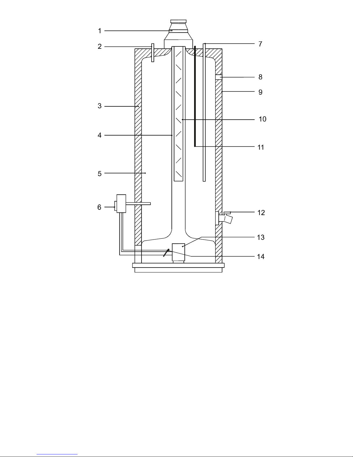
1) Draught diverter
2) Hot water outlet
3) Insulation
4) Flue tube
5) Glass lined tank
6) Gas control valve
7) Cold water inlet
8) T&P valve connection
9) Outer casing
Figure 1 - Cross-section of the heater
10) Flue bafe
11) Sacricial anode
12) Drain tap
13) Atmospheric burner
14) Pilot light burner with
thermocouple
AOS 047
8

6
1.2 Technical safety
equipment
1.2.1 Gas control valve
The water heater has been tted with
a gas control block consisting of a
thermo-electrical pilot ame safeguard,
pilot ame pressure regulator, burner
pressure regulator, a control thermostat
(adjustable between 30°C and 71°C)
and a safety thermostat (82°C). This gas
control block with its simple and secure
control respectively switches the gas
supply to the main burner on or off.
This gas control block is suitable for
gasses from the rst, second and third
gas family. The maximum inlet pressure
is 50 mbar.
1.2.2 Combustion products
discharge safety device
The water heater has been tted with a
combustion products discharge safety
device. It is the function of the safety
device to prevent ue gasses from the
water heater entering the room where
the water heater has been placed,
instead of passing through the ue to
outside atmosphere. The gas supply is
disconnected as soon as the device is
activated by hot gasses owing over
the sensor.
After the cause of the re-entry of ue
gasses has been traced the device can
be put back into operation by pressing its
reset button.
If this faillure occurs frequently, this
indicates that the ue suffers from down
draught conditions. It is recommended
that a competent person carry out the
necessary remendial action.
Important
The combustion products discharge
safety device should never be put out
of operation. Re-entry of ue gasses
to the building could be harmful and
cause poisoning or death.
7
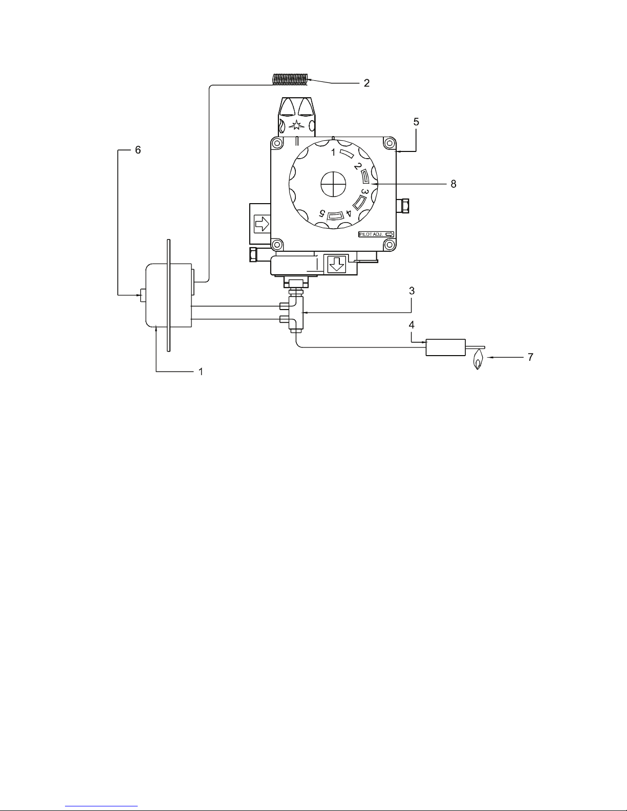
Figure 2 - Combustion products
discharge safety device with gas
control valve
1) Combustion products discharge
safety device thermostat
2) Sensor Combustion products
discharge safety device
thermostat
3) Thermocouple with built-in
interrupter
4) Thermocouple
5) Gas control block
6) Reset button
7) Pilot burner
8) Temperature regulator knob
AOS 0479

8
1.3 Technical information
1.3.1 Dimensions
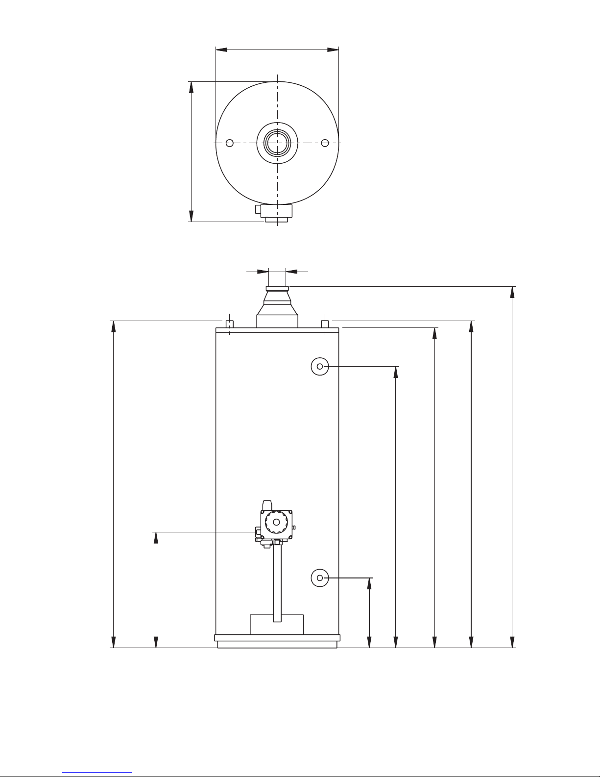
These water heaters are only suitable for
a ue tube with minimal the announced
diameter (dimension G).
Dimen-
sions LG 30 LG 40 LG 50
(see draw.3)
A 1280 1370 1670
B 1120 1210 1540
D 465 515 515
E 545 595 605
G 80 80 100
K 325 325 380
M
110 120
1590
N
110 120
1590
R
20 20
255
S
965 1045
1380
1 Cold water inlet
2 Hot water outlet
3 Gas control valve
4 Drain tap
5 T&P valve tapping
All dimensions are given in mm.
(rounded off on 5 mm).See gure 3.
9
Figure 3 - Dimensions
IMD-0266
N
K
3
A
S
4
R
B
M
5
G
E
2
D
1
 Loading...