

Lochinvar HERALD HCB46CE, HERALD HCB61CE, HERALD HCB86CE, HERALD HCB116CE, HERALD HCB146CE Installation Manual
...
1
installation manual_herald 46-86_februaury 2018
HERALD
FLOOR STANDING GAS FIRED
CONDENSING BOILERS
Installation, Commissioning, Maintenance and User
Instructions
MODELS:
HCB46CE
HCB61CE
HCB86CE

2
Table of Contents
1.0 INTRODUCTION ...................................................................................................................................................................................................................................... 4
2.0 SAFETY GUIDELINES............................................................................................................................................................................................................................. 5
2.1 GENERAL DESCRIPTION OF SAFETY SYMBOLS USED............................................................................................................................................................ 5
2.2 WHAT TO DO IF YOU SMELL GAS ................................................................................................................................................................................................ 6
3.0 PRINCIPAL PARTS ................................................................................................................................................................................................................................. 7
4.0 TECHNICAL DATA .................................................................................................................................................................................................................................. 9
5.0 DIMENSIONS AND CLEARANCES ...................................................................................................................................................................................................... 10
5.1 DIMENSIONAL DRAWINGS .......................................................................................................................................................................................................... 10
5.2 CLEARANCES ................................................................................................................................................................................................................................ 11
6.0 GENERAL REQUIREMENTS ................................................................................................................................................................................................................ 12
6.1 RELATED DOCUMENTS ............................................................................................................................................................................................................... 12
7.0 WATER QUALITY .................................................................................................................................................................................................................................. 13
8.0 LOCATION ............................................................................................................................................................................................................................................. 13
8.1 PLANT ROOM REQUIREMENTS .................................................................................................................................................................................................. 13
8.2 GENERAL REQUIREMENTS ......................................................................................................................................................................................................... 13
8.3 CLEARANCES ................................................................................................................................................................................................................................ 14
8.4 CONDENSATE DRAIN ................................................................................................................................................................................................................... 14
9.0 GAS SUPPLY ......................................................................................................................................................................................................................................... 14
9.1 SERVICE PIPES ............................................................................................................................................................................................................................. 14
9.2 METERS.......................................................................................................................................................................................................................................... 14
9.3 GAS SUPPLY PIPES ...................................................................................................................................................................................................................... 14
9.4 BOOSTED SUPPLIES .................................................................................................................................................................................................................... 14
9.5 PLANT-ROOM CONTROL VALVE ................................................................................................................................................................................................ 14
10.0 FLUE SYSTEM ....................................................................................................................................................................................................................................... 16
10.1 FLUE SYSTEM GENERAL REQUIREMENTS .............................................................................................................................................................................. 16
10.2 FLUE SYSTEM TECHNICAL DETAILS ......................................................................................................................................................................................... 17
10.3 FLUE DISCHARGE......................................................................................................................................................................................................................... 17
10.4 CONDENSATE DRAIN ................................................................................................................................................................................................................... 17
10.5 APPROVED FLUE SYSTEM .......................................................................................................................................................................................................... 19
10.6 INSTALLATION PRECAUTIONS ................................................................................................................................................................................................... 19
10.1 ROOM SEALED (TYPE C) FLUE ASSEMBLY .............................................................................................................................................................................. 20
10.2 INSTALLATION OF FLUE TRANSITION KIT TO HCB46CE-HCB61CE BOILERS ..................................................................................................................... 20
10.3 INSTALLATION OF TRANSITION KIT TO HCB86CE BOILER .................................................................................................................................................... 22
11.0 FLUE TERMINAL INSTALLATION ....................................................................................................................................................................................................... 25
11.1 TYPE C
13
(Horizontal room sealed) ................................................................................................................................................................................................ 25
11.2 FLUE TERMINAL GUARDING ....................................................................................................................................................................................................... 26
11.4 TYPE C
33
(Vertical room sealed) .................................................................................................................................................................................................... 28
11.5 TYPE C
43
(U duct) ........................................................................................................................................................................................................................... 34
11.6 TYPE C
53
(Twin pipe) ...................................................................................................................................................................................................................... 34
11.7 TYPE B23 (Conventional flue with fan assistance) ......................................................................................................................................................................... 39
11.8 C63 Certified Flue Systems ............................................................................................................................................................................................................ 40
12.0 AIR SUPPLY .......................................................................................................................................................................................................................................... 41
12.1 COMBUSTION VENTILATION ....................................................................................................................................................................................................... 41
12.2 COOLING VENTILATION ............................................................................................................................................................................................................... 41
13.0 WATER CONNECTIONS ....................................................................................................................................................................................................................... 42
13.1 GENERAL ....................................................................................................................................................................................................................................... 42
13.2 OPEN VENTED SYSTEM ARRANGEMENT ................................................................................................................................................................................. 42
13.3 SEALED SYSTEM ARRANGEMENT............................................................................................................................................................................................. 42
14.0 SCHEMATICS ........................................................................................................................................................................................................................................ 44
14.1 key for schematics .......................................................................................................................................................................................................................... 44
14.2 CIRCULATING PUMPS .................................................................................................................................................................................................................. 47
14.3 PRIMARY PIPEWORK HEADER SIZING ...................................................................................................................................................................................... 48
15.0 ELECTRICAL SUPPLY ......................................................................................................................................................................................................................... 49
15.2 EXTERNAL CONTROLS ................................................................................................................................................................................................................ 49
15.3 HIGH VOLTAGE CONNECTOR STRIP ......................................................................................................................................................................................... 50
15.4 LOW VOLTAGE CONNECTOR STRIP ......................................................................................................................................................................................... 50
15.5 ELECTRICAL CONNECTIONS ...................................................................................................................................................................................................... 52
15.6 FUSES ............................................................................................................................................................................................................................................. 52
15.7 ARC WELDING PRECAUTIONS ................................................................................................................................................................................................... 52
15.8 WIRING DIAGRAM ......................................................................................................................................................................................................................... 53
15.9 LADDER DIAGRAM ........................................................................................................................................................................................................................ 54
16.0 SMART SYSTEM CONTROL ................................................................................................................................................................................................................ 55
16.1 GENERAL ....................................................................................................................................................................................................................................... 55
16.2 SMART SYSTEM CONTROL PANEL ............................................................................................................................................................................................ 55
ACCESS MODES ........................................................................................................................................................................................................................... 55
16.3 SAVING PARAMETERS................................................................................................................................................................................................................. 56
16.4 STATUS DISPLAY SCREENS ....................................................................................................................................................................................................... 58
17.0 COMMISSIONING AND TESTING ........................................................................................................................................................................................................ 60
17.1 ELECTRICAL INSTALLATION ....................................................................................................................................................................................................... 60
17.2 GAS INSTALLATION ...................................................................................................................................................................................................................... 60
17.3 WATER CONNECTIONS ............................................................................................................................................................................................................... 60
17.4 COMMISSIONING THE EQUIPMENT ........................................................................................................................................................................................... 60
17.5 TEMPERATURE ADJUSTMENT PROCEDURE ........................................................................................................................................................................... 61
17.6 INSTALLATION NOISE .................................................................................................................................................................................................................. 61
18.0 LPG FUEL .............................................................................................................................................................................................................................................. 62
18.1 RELATED DOCUMENTS ............................................................................................................................................................................................................... 62
18.2 CONVERSION TO LPG .................................................................................................................................................................................................................. 62
18.3 LPG COMMISSIONING AND TESTING ........................................................................................................................................................................................ 64
19.0 MAINTENANCE ..................................................................................................................................................................................................................................... 65
19.1 GENERAL ....................................................................................................................................................................................................................................... 65
19.2 MAINTENANCE SCHEDULE ......................................................................................................................................................................................................... 65
19.3 BURNER INSPECTION .................................................................................................................................................................................................................. 65

3
19.4 BURNER REMOVAL ...................................................................................................................................................................................................................... 66
19.5 CLEANING THE HEAT EXCHANGER .......................................................................................................................................................................................... 66
19.6 DRAINING BOILER SYSTEM ........................................................................................................................................................................................................ 66
19.7 REFILLING THE SYSTEM ............................................................................................................................................................................................................. 67
19.8 OTHER CHECKS ............................................................................................................................................................................................................................ 67
20.0 SMART SYSTEM CONTROL SETTINGS ............................................................................................................................................................................................. 68
20.1 DISPLAY PANEL ACCESS MENU ................................................................................................................................................................................................ 68
20.2 PARAMETER SETTING ................................................................................................................................................................................................................. 69
21.0 VIEWABLE AND CHANGEABLE CONTROL PARAMETERS ........................................................................................................................................................... 73
21.1 GENERAL ....................................................................................................................................................................................................................................... 73
21.2 TEMPERATURE SETTINGS .......................................................................................................................................................................................................... 74
21.3 DATA LOGGING ............................................................................................................................................................................................................................. 75
21.4 FUNCTIONS ................................................................................................................................................................................................................................... 75
21.5 DHW SETTINGS ............................................................................................................................................................................................................................. 76
21.6 OUTDOOR RESET ......................................................................................................................................................................................................................... 78
21.7 ANTI-CYCLING ............................................................................................................................................................................................................................... 80
21.8 RAMP SETTINGS ........................................................................................................................................................................................................................... 81
21.9 CONTROL MODES ........................................................................................................................................................................................................................ 81
21.10 BUILDING MANAGEMENT SYSTEM (BMS) ......................................................................................................................................................................... 83
21.11 CIRCULATION PUMPS .......................................................................................................................................................................................................... 85
21.12 SERVICE NOTIFICATION ...................................................................................................................................................................................................... 86
21.13 BASIC SETUP ......................................................................................................................................................................................................................... 87
22.0 ErP DATA TABLE .................................................................................................................................................................................................................................. 88
23.0 USER INSTRUCTIONS .......................................................................................................................................................................................................................... 89
23.1 GENERAL REQUIREMENTS ......................................................................................................................................................................................................... 89
23.2 PROCEDURE FOR LIGHTING ...................................................................................................................................................................................................... 89
23.3 PROCEDURE FOR SHUTTING DOWN ........................................................................................................................................................................................ 89
23.4 SMART SYSTEM CONTROL ......................................................................................................................................................................................................... 90
23.5 TEMPERATURE ADJUSTMENT PROCEDURE ........................................................................................................................................................................... 90
23.6 MAINTENANCE .............................................................................................................................................................................................................................. 91
23.7 AIR SUPPLY ................................................................................................................................................................................................................................... 91
23.8 ENTERING DISPLAY ACCESS USER PASSWORD ................................................................................................................................................................... 91
23.9 PARAMETER SETTINGS............................................................................................................................................................................................................... 91

4
1.0 INTRODUCTION
The Lochinvar Herald range is a floor standing gas fired condensing boiler. The equipment comprises a
stainless steel radial burner assembly and a heat exchanger that permits fully condensing operation.
The burner is initiated by a full electronic ignition sequence control that incorporates a spark ignition and a
flame rectification device for supervision of the flame.
The output from the boiler is regulated by a variable speed combustion fan and gas/air ratio controls to maintain
the correct combustion at all levels of modulation. This configuration allows modulation down to 20% of the
rated output.
For the correct operation of the boiler, it is essential that a suitably sized pump is utilised to maintain a constant
water flow rate through the heat exchanger. A suitable shunt pump is available as an ancillary option from
Lochinvar Ltd. See section 14.2.2
This equipment is intended for use on Group H Natural Gas (2
nd
Family) and LPG propane (3rd Family). The
information relating to propane firing is to be found in Section 18.0: LPG FUEL. This equipment MUST NOT
use gas other than that for which it has been designed and adjusted.
This equipment must be installed by a competent person, registered with a H.S.E. approved body. All
installations must conform to the relevant Gas Safety and Building Regulations. Health & Safety requirements
must also be taken into account when installing any equipment. Failure to comply with the above may lead to
prosecution.
If the equipment is to be connected to an unvented (pressurised) system, care must be taken to ensure all
extra safety requirements are satisfied should a high or low-pressure condition occur in the system.
The equipment is designed for direct connection to a flue system.
Ancillary Options:
Primary shunt Pumps See section 14.2.2
DHW vessel sensor LL200009A
Outside sensor for direct weather compensation of boiler LL200010A
Con-X-Us Remote Monitoring App LL100071724
Pressurisation Unit
o Wall mounted – single pump CHCWM1
o Wall mounted – twin pump CHCWM2
Condensate Neutralisation Kit KIT2000
Low Velocity Header Contact Lochinvar Limited
Flue System Components See flue assemblies guide
Plate system separator Contact Lochinvar Limited
ModBus Interface Module LL100297842
BACnet Interface Module LL100297828

5
2.0 SAFETY GUIDELINES
READ AND UNDERSTAND THE INSTRUCTIONS
Read and fully understand all instructions before attempting to operate maintain or install the
unit.
Keep these instructions near the Boiler for quick reference.
This equipment must be installed by a competent person, registered with the H.S.E. approved body. All installations
must conform to the relevant Gas Safety and Building Regulations. Health & Safety requirements must also be
taken into account when installing any equipment. Failure to comply with the above may lead to prosecution
Without written approval of the manufacturer the internals of the boiler may not be changed. When changes are executed
without approval, the boiler certification becomes invalid.
Commissioning, maintenance and repair must be done by a skilled installer/engineer, according to all applicable
standards and regulations.
2.1 GENERAL DESCRIPTION OF SAFETY SYMBOLS USED
BANNED
A black symbol inside a red circle with a red diagonal indicates an action that should not be
performed
WARNING
A black symbol added to a yellow triangle with black edges indicates danger
ACTION REQUIRED
A white symbol inserted in a blue circle indicates an action that must be taken to avoid risk
ELECTRICAL HAZARD
Observe all signs placed next to the pictogram. the symbol indicates components of the unit
and actions described in this manual that could create an electrical hazard.
HOT SURFACES
The symbol indicates those components with a high surface temperature that could create a
risk.
This symbol shows essential information which is not safety related
Recover or recycle material

6
2.2 WHAT TO DO IF YOU SMELL GAS
Warning if you smell gas
No naked flames, no smoking!
Avoid causing sparks, do not switch on or off electrical equipment or lights
Open windows and doors
Shut off the main gas supply
Warn occupants and leave the building
After leaving the building alert the local gas supply company
Do not re-enter the building until it is safe to do so
Lochinvar limited is not liable for any damage caused by inaccurately following these
mounting instructions. Only original parts may be used when carrying out any repair or
service work.
This appliance is not intended for use by persons (including children) with reduced physical,
sensory or mental capabilities, or lack of experience and knowledge, unless they have been
given supervision or instruction concerning use of the appliance by a person responsible for
their safety. Children should be supervised to ensure that they do not play with the appliance.

7
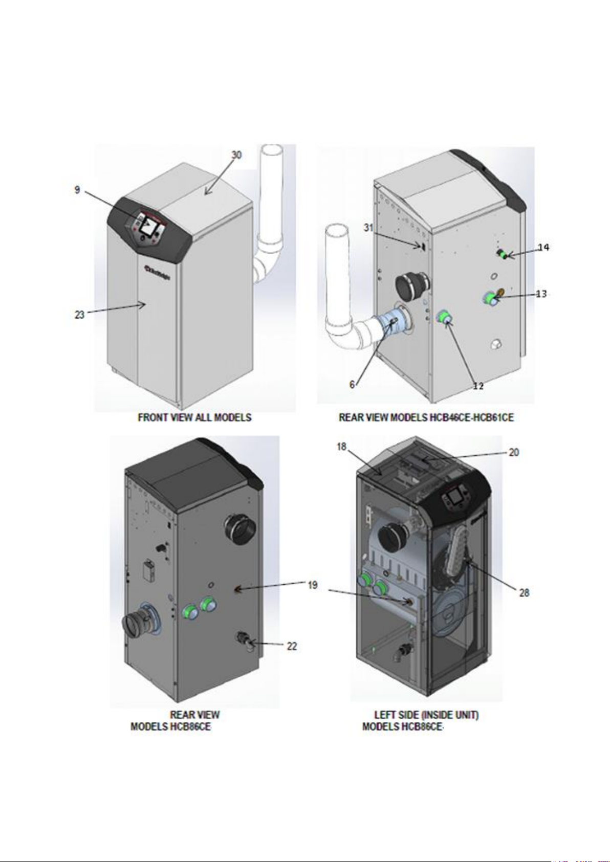
3.0 PRINCIPAL PARTS
ITEM
DESCRIPTION
FUNCTION
NOTE
1
Stainless steel heat
exchanger
Allows water to flow through specially designed coils for maximum heat transfer, while providing protection
against flue gas corrosion. The coils are encased in a jacket that contains the combustion process.
Not Shown in 3.1.2
2
Heat exchanger access
cover
Allows access to the combustion side of the heat exchanger coils.
Not Shown in 3.1.2
3
Fan
The fan pulls in air and gas through the venturi (item 5). Air and gas mix inside the fan and are pushed into
the burner, where they burn inside the combustion chamber.
Not Shown in 3.1.2
4
Gas valve
The gas valve senses the negative pressure created by the fan, allowing gas to flow only if the gas valve is
powered and combustion air is flowing.
Not Shown in 3.1.2
5
Venturi
The venturi controls air and gas flow into the burner.
Not Shown in 3.1.2
6
Flue gas sensor
This sensor monitors the flue gas exit temperature. The control module will modulate and shut down the boiler
if the flue gas temperature gets too hot. This protects the flue pipe from overheating.
7
Boiler outlet temperature
sensor
This sensor monitors boiler outlet water temperature.
Not Shown in 3.1.2
8
Boiler inlet temperature
sensor
This sensor monitors return water temperature.
Not Shown in 3.1.2
9
Electronic display
The electronic display consists of 7 buttons and a dual line 32-character liquid crystal display.
10
Flue pipe adapter
Allows for the connection of the flue system to the boiler.
Not Shown in 3.1.2
11
Burner
Made with metal fibre and stainless steel construction, the burner uses pre-mixed air and gas and provides a
wide range of firing rates.
12
Water outlet
BSP water connection that supplies hot water to the system, either 1-1/4" or 2", depending on the model.
13
Water inlet
BSP water connection that returns water from the system to the heat exchanger, either 1-1/4" or 2", depending
on the model.
14
Gas connection pipe
Threaded pipe connection, 1/2 “, 3/4", or 1", depending on the model. This pipe should be connected to the
incoming gas supply for the purpose of delivering gas to the boiler.
15
SMART Control Module
The SMART Control responds to internal and external signals and controls the fan, gas valve, and pumps to
meet the demand.
Not Shown in 3.1.2
16
Manual air vent
Designed to remove trapped air from the heat exchanger coils.
Not Shown in 3.1.2
17
Air intake adapter
Allows for the connection of the air intake pipe to the boiler.
Not Shown in 3.1.2
18
Mains voltage junction
box
The junction box contains the connection points for the mains voltage power and all pumps.
19
Boiler drain port
Location from which the heat exchanger can be drained.
20
Low voltage connection
board
The connection board is used to connect external low voltage devices.
21
Low voltage wiring
connections (knockouts)
Conduit connection points for the low voltage connection board.
Not Shown in 3.1.2
22
Condensate drain
connection
Connects the condensate drain line to a 1/2" PVC union.
23
Access cover - front
Provides access to the gas train and the heat exchanger.
24
Ignition electrode
Provides direct spark for igniting the burner.
Not Shown in 3.1.2
25
Flame inspection window
The quartz glass window provides a view of the burner surface and flame.
Not Shown in 3.1.2
26
Gas shutoff valve
Manual valve used to isolate the gas valve from the gas supply.
Not Shown in 3.1.2
27
High limit sensor
Device that monitors the outlet water temperature. If the temperature exceeds its setting, it will break the
control circuit, shutting the boiler down.
Not Shown in 3.1.2
28
Flame sense electrode
Used by the control module to detect the presence of burner flame.
29
Mains voltage wiring
connections (knockouts)
Conduit connection points for the mains voltage junction box
Not Shown in 3.1.2
30
Top panel
Removable panel to gain access to the internal components.
31
Power switch
Turns 230 VAC ON/OFF to the boiler.
32
Levelling legs
Used to allow the heat exchanger to be levelled. This is needed for the proper draining of the condensate
from the combustion chamber
Not Shown in 3.1.2
3.1.1 PRINCIPLE PARTS LIST, TO BE USED IN CONJUNCTION WITH 3.1.2
8
3.1.2 PRINCIPLE PARTS TO BE USED IN CONJUNCTION WITH TABLE 3.1.1
9
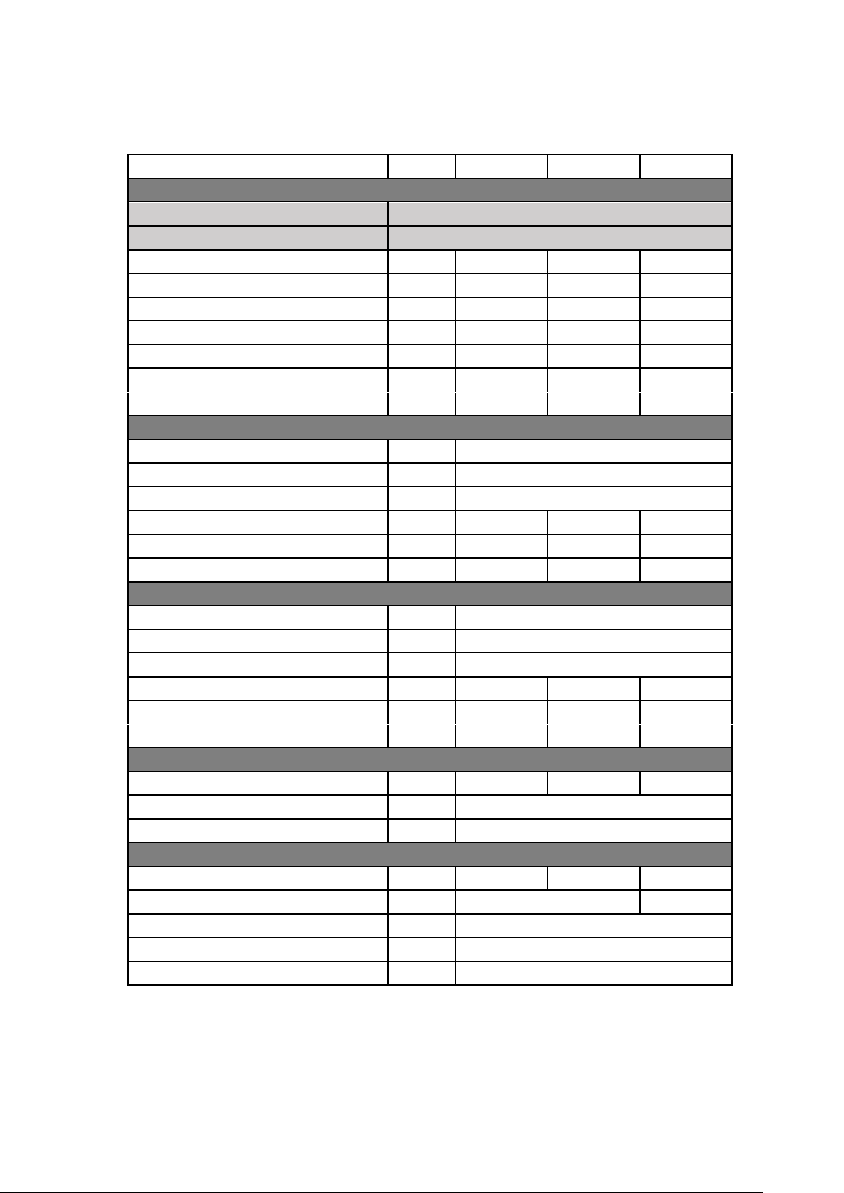
4.0 TECHNICAL DATA
Model Number
HCB46CE
HCB61CE
HCB86CE
GENERAL DATA
Product I.D. Number
CE 0063 CQ3351
Classification
112H31B/P
Input (gross)
kW
44
61.5
83.5
Input (net)
kW
39.6
55.4
75.2
Output (50º/30º)
kW
41.2
58.7
79.7
Output (80º/60º)
kW
38.5
53.2
71
Seasonal Efficiency
%
96.4
95.6
96
Shipping Weight
kg
75
79
102
NOX @0%O2
mg/kWh
39
39
39
GAS DATA – G20
Nominal gas inlet pressure
mbar
20
Maximum gas inlet pressure
mbar
25
Minimum gas inlet pressure
mbar
17.5
Gas flow rate
m3/hr
4.2
5.9
8
Flue gas mass rate (@ 9.0% CO2)
g/sec
16
22.3
30.4
Gas inlet connection size
“ BSP ½ ½
¾
GAS DATA – G31
Nominal gas inlet pressure
mbar
37
Maximum gas inlet pressure
mbar
45
Minimum gas inlet pressure
mbar
27
Gas flow rate – m3/hr
m3/hr
1.7
2.3
3.1
Flue gas mass rate (@ 10.5% CO2)
g/sec
16.7
23.2
31.6
Gas inlet connection size
“ BSP ½ ½
¾
ELECTRICAL DATA
Power consumption
W
120
144
180
Power supply Single phase 230v/50Hz
Protection class
IP00
WATER DATA
Water content
litres
4.9
6.4
9.1
Water connections (F & R)
“ BSP
1 ¼
2
Max. water pressure (PMS)
bar
11
Min. water pressure
bar
0.5
Maximum water temperature
°C
80
4.1.1 TECHNICAL DATA TABLE
10
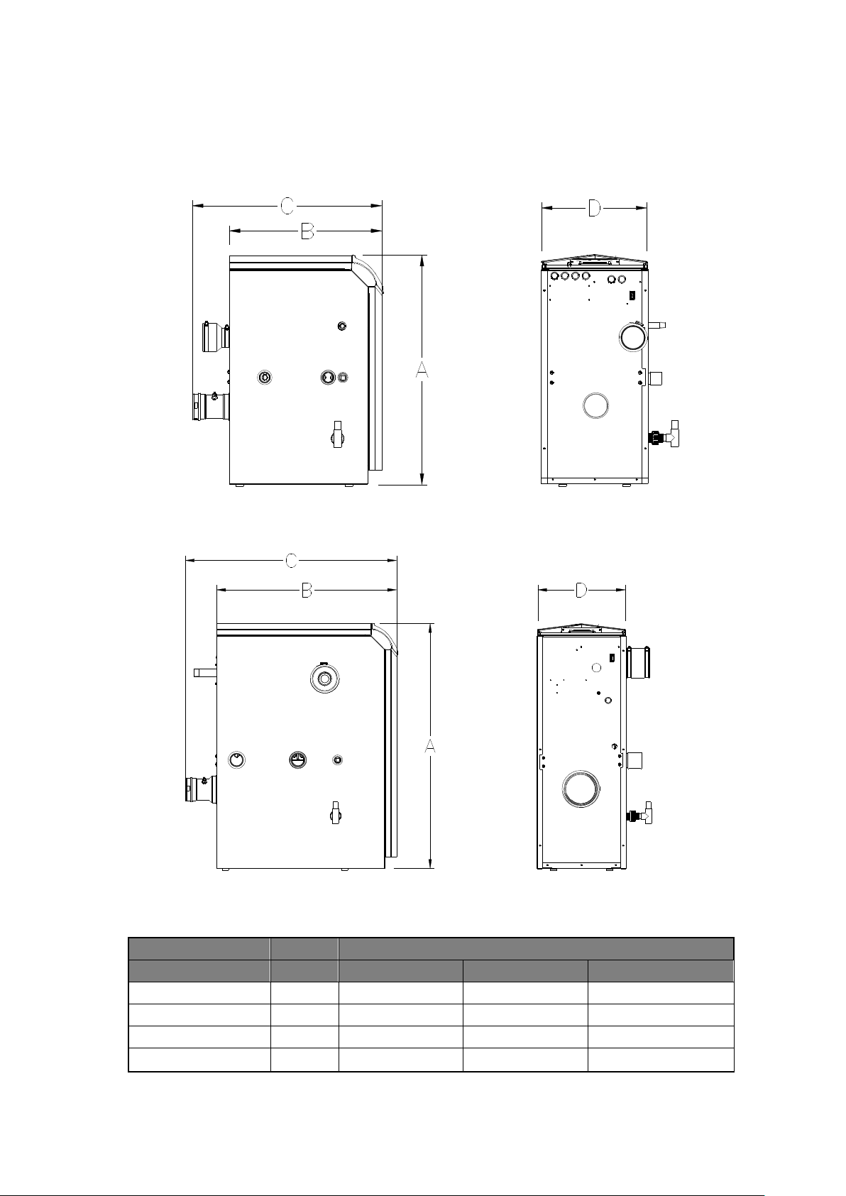
5.0 DIMENSIONS AND CLEARANCES
5.1 DIMENSIONAL DRAWINGS
Note full dimensional drawings showing connection sizes and positions are available from Lochinvar technical support
5.1.1 DIMENSIONAL DRAWING MODEL HCB46CE-HCB61CE
5.1.2 DIMENSIONAL DRAWING MODELS, HCB86CE
Model
Dimension
Unit
HCB46CE
HCB61CE
HCB86CE
A
mm
845
845
1080
B
mm
457
565
502
C
mm
701
701
641
D
mm
394
394
394
11
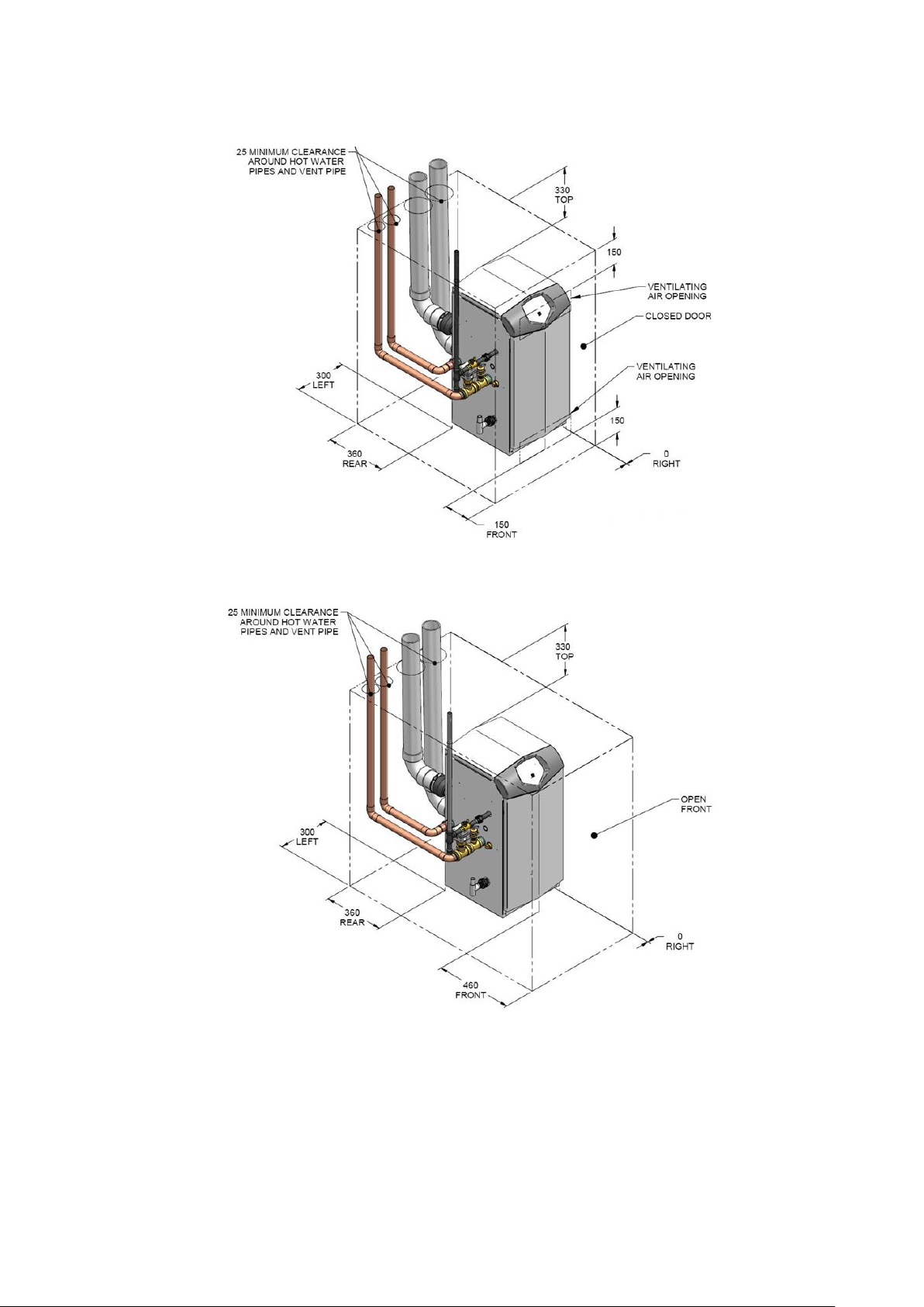
5.2 CLEARANCES
5.2.1 ENCLOSURE INSTALLATION CLEARANCES (MM)
5.2.2 PLANT-ROOM INSTALLATION CLEARANCES (MM)
12
6.0 GENERAL REQUIREMENTS
The Lochinvar Herald condensing boiler has been designed to operate trouble free for many years. These instructions
should be followed closely to obtain the maximum usage and efficiency of the equipment.
READ AND UNDERSTAND THE INSTRUCTIONS
Read and fully understand all instructions before attempting to operate maintain or install the
unit.
6.1 RELATED DOCUMENTS
It is law that all gas appliances are installed by competent persons, in accordance with The Gas Safety (Installation and
Use) Regulations 1998. Failure to install appliances correctly could lead to prosecution. It is in your own interest, and
that of safety, to ensure that this law is complied with.
The installation of the equipment MUST be in accordance with the relevant requirements of the Gas Safety Regulations,
Building Regulations, I.E.E. Regulations and the bylaws of the local water undertaking. The installation should also be
in accordance with any relevant requirements of the local gas distributor and local authority.
In addition, the installation should follow the relevant guidance offered in the following documents. It is not practical to
list all relevant information but emphasis is placed on the following documents, as failure to comply with the guidance
given will almost certainly result in an unsatisfactory installation:
Regulation
Description
BS EN 1858: 2008 + A1:
2011
Chimneys, Components. Concrete flue blocks.
BS 5440-1: 2008
Flueing and ventilation for gas appliances of rated input not exceeding 70 kW net (1st, 2nd and 3rd family gases).
Specification for installation of gas appliances to chimneys and for maintenance of chimneys.
BS 5440-2: 2009
Installation and maintenance of flues and ventilation for gas appliances of rated input not exceeding 70 kW net
(1st, 2nd and 3rd family gases). Specification for installation and maintenance of ventilation for gas appliances.
BS 6644: 2011
Specification for Installation of gas-fired hot water boilers of rated inputs between 70 kW (net) and 1.8 MW (net)
(2nd and 3rd family gases).
BS 6700: 2006 +A1: 2009
Design, installation, testing and maintenance of services supplying water for domestic use within buildings and
their curtilages.
BS 6880: 1988 Parts 1, 2 and
3
Code of practice for low temperature hot water systems of output greater than 45 kW.
BS 7074: 1989 Parts 1 and 2
Application, selection and installation of expansion vessels and ancillary equipment for sealed systems.
BS 7671: 2008 + A3:2015
Requirements for electrical installations, I.E.E. wiring regulations seventeenth edition.
BS 7671: Amendment 2:
August 2013
BSEN
12828:2012+A1:2014
Heating systems in buildings. Design for water-based heating systems.
CP 342 (Part 2 1974):
Code of practice for centralised hot water supply-buildings other than dwellings.
Institute of Gas Engineers and Managers (IGEM) Publications
IGE/UP/1 - Edition 2:
Installation pipework on industrial and commercial premises.
IGEM/UP/2 – Edition 3:
Gas installation pipework, boosters and compressors on industrial and commercial premises.
IGEM/UP/4 - Edition 4:
Commissioning of gas-fired plant on industrial and commercial premises.
IGEM/UP/10 - Edition 4:
Installation of flued gas appliances in industrial and commercial premises.
Gas Safety (Installation and Use) Regulations 1998
CIBSE: Guides
Part A Environmental Design
Part G Public health engineering
H.S.E. guidance
INDG 436 Safe management of industrial steam & hot water boilers
SAFED BG01Guidance on safe operation of boilers
Third edition of the 1956 Clean Air Act Memorandum on Chimney Heights
Manufacturer's notes must not be taken in any way as overriding statutory obligations.

13
7.0 WATER QUALITY
The Lochinvar Herald contains a stainless steel heat exchanger; therefore, care must be exercised to ensure that the
system water and any water treatment are compatible. Whenever a new boiler is connected to an existing system, the
pipework must be thoroughly cleaned and flushed to remove debris, rust particles, carbonate deposits and any existing
water treatment that might be incompatible with the heat exchanger. If the existing system is in poor condition and/or
cannot be pressurised, then consideration should be given to using a Plate system separator. See Section 13.3.2 for
details, new systems must also be thoroughly flushed to remove debris and flux deposits.
Failure of the heat exchanger due to deposits in the water are not covered under the boiler
warranty. For advice on system treatment or separation contact Lochinvar technical support.
Whilst chemical inhibitors remove oxygen from the water, due to uncertainty in dosing levels, there is the possibility that
the inhibitor will eventually be diluted to the point where it is no longer effective. To ensure there is effective air
separation and removal, an air separator should be fitted to the hottest part of the system, in accordance with the item
manufacturer’s instructions. In addition to this a means of dirt removal (e.g. dirt separator or strainer) should be fitted
to the boiler return pipework to prevent the accumulation of debris within the heat exchanger coils.
The use of chemical inhibitors alone will not satisfy the terms of the heat exchanger warranty.
8.0 LOCATION
8.1 PLANT ROOM REQUIREMENTS
The Lochinvar Herald may only be installed in a room that complies with the appropriate ventilation requirements.
The Lochinvar Herald can be used as a type C13, C33, C43 or C53 (room sealed) appliance. Due to its room sealed
design, ventilation allowances for combustion air are not necessary, provided the minimum clearances and service
clearances as detailed in
PLANT-ROOM INSTALLATION CLEARANCES (mm) are observed. If the appliance is to be installed in a
compartment or a hot environment, the minimum clearances detailed in
ENCLOSURE INSTALLATION CLEARANCES (mm) should be observed. In addition to this, ventilation for cooling
purposes must be fitted. For further guidance, please refer to Section on AIR SUPPLY or to BS5440-2 or BS6644 as
appropriate.
The Lochinvar Herald can also be used as a type B23 (open flue) appliance. If such a configuration is to be used, then
appropriate ventilation for cooling and combustion must be provided. For further details, please refer to Section on
AIR SUPPLY or to BS5440-2 or BS6644 as appropriate.
8.2 GENERAL REQUIREMENTS
Corrosion of the heat exchanger coils and flue system may occur if air for combustion contains certain chemical vapours.
Such corrosion may result in poor combustion and create a risk of asphyxiation. Aerosol propellants, cleaning solvents,
refrigerator and air conditioning refrigerants, swimming pool chemicals, calcium and sodium chloride, waxes and
process chemicals are corrosive. Products of this sort should not be stored near the boiler or outside by the air intake
(if applicable). The fitting of this equipment in a situation where aerosols or other chemicals may be entrained into the
combustion air will invalidate the warranty.
The equipment must be installed on a level surface that is capable of adequately supporting its weight (when filled with
water) and any ancillary equipment. The operation of the equipment must not cause the temperature of any combustible
material in the vicinity of the equipment and its flue to exceed 65°C. If such a situation is unavoidable, appropriate
insulation should be provided.
Locate the equipment so that if the appliance or any connecting pipework should leak, water
damage will not occur. When such locations cannot be avoided it is recommended that a
suitable drain pan be installed under the equipment. The pan should be adequately drained but
must not restrict the combustion or ventilation airflow.

14
8.3 CLEARANCES
The location chosen for the equipment must permit the provision for a satisfactory flue system and, where necessary,
an adequate air supply. The location must also provide adequate space for servicing and air circulation around each
unit. This includes any electrical trunking laid across the floor and to the appliance.
See
PLANT-ROOM INSTALLATION CLEARANCES (mm)
For dimensions/clearances. Further details regarding locations are given in BS5440 or BS6644 as appropriate.
8.4 CONDENSATE DRAIN
The condensate drain is located on the left hand side of the boiler. It is fitted with a ½” PVC tee and union, this should
be connected to an appropriate condensate drain, sloping continuously away from the boiler at an angle of at least 3
(50mm per metre).
The Water Resources Act requires that trade effluent is discharged to municipal sewers between pH 6.5 and 10.0. If it
is determined that these levels cannot be achieved, an in-line condensate neutralisation kit is available from Lochinvar
Limited. This unit is capable of neutralising 4000 litres of condensate to a pH of 7.0 before releasing it to a drain.
9.0 GAS SUPPLY
The Lochinvar Herald range is suitable for use on second and third family gasses 2H - G20 - 20mbar and 3P - G31 37mbar. For details relating to Propane (3P) please refer to Section on LPG FUEL:
9.1 SERVICE PIPES
The local gas distributor must be consulted at the installation planning stage in order to establish the availability of an
adequate supply of gas. An existing service pipe must not be used without prior consultation with the local gas
distributor.
9.2 METERS
A new gas meter will be connected to the service pipe by the local gas distributor contractor. An existing gas meter
should be checked, preferably by the gas distributor, to ensure that it is adequate to deal with the rate of gas supply
required.
9.3 GAS SUPPLY PIPES
Supply pipes must be fitted in accordance with IGE/UP/2. Pipework from the meter to the equipment must be of
adequate size. The complete installation must be purged and tested as described in IGE/UP/1. Refer to Section on
LPG FUEL for information on LPG pipework installation guidance.
9.4 BOOSTED SUPPLIES
Where it is necessary to employ a gas pressure booster, the controls must include a low-pressure cut-off switch at the
booster inlet. The local gas distributor must be consulted before a gas pressure booster is fitted. For details of how to
connect a low-pressure cut-off switch, please refer to Section 15.0
9.5 PLANT-ROOM CONTROL VALVE
A manual valve for plant-room isolation must be fitted in the gas supply line. It must be clearly identified and readily
accessible for operation, preferably by an exit.

15
EQUIPMENT GAS SYSTEM LEAK CHECK
An approved gas-inlet appliance isolating valve and union should be installed for each unit in a convenient and
safe position and be clearly marked. Ensure that the gas-inlet appliance isolating valve is in the OFF position.
Although the equipment receives a gas leak check and gas train component integrity check prior to leaving the factory,
transit and installation may cause disturbance to unions, fittings and components. During commissioning a further test
for tightness should be carried out on the equipment gas pipework and components.
Care must be taken not to allow leak detection fluid on or near any electrical parts or
connections.

16
10.0 FLUE SYSTEM
All versions of the Herald Condensing boiler can be installed as either type B23 (fan assisted open flue) or C13, 33,
C53 (room sealed) appliances. See the relevant section for details of each flue type and requirements. Standard flue
kits are available as an ancillary item, these include the standard pieces to start the flue system, additional elbows,
extensions will probably be required depending upon site installation requirements. Further information including part
numbers is available in the separate flue guide available from www.lochinvar.ltd.uk
10.1 FLUE SYSTEM GENERAL REQUIREMENTS
Install the horizontal flue components with an angle of 3° back in the direction of the boiler
(roughly equal to five centimetres for every linear meter). Failure to install the flue correctly will
result in a build-up of condense within the flue pipework that will cause early component failure.
When using a wall terminal, there is the possible risk of ice building-up on surrounding
parts/structures, because the condensate will freeze. This risk should be taken into account
during the design phase of the heating installation.
Herald boilers will produce large condense clouds especially during cold weather,
consideration must be taken as to whether this will cause a nuisance to neighbouring
properties and if so alternative flue arrangements used.
Herald boilers can operate with very low flue temperatures; as such the flue system used must
be suitable for use with condensing appliances made from either Polypropylene or stainless
steel and have a temperature class of T120.
Aluminium flue pipe must not be used on this appliance as it may lead to premature failure of
the heat exchanger and will invalidate the warranty.
Before installation of any flue system read the installation manual carefully for both the
appliance and flue system to be used. Information on the flue system Supplied by Lochinvar
can be found within this manual.
Detailed recommendations for the flue system are given in BS5440-1 for equipment of rated input not exceeding 70kW
net, BS6644 for equipment above 70kW net and IGE/UP/10 for equipment of rated input above 54kW net. The following
notes are intended to give general guidance only.

17
10.2 FLUE SYSTEM TECHNICAL DETAILS
Model Number
HCB46CE
HCB61CE
HCB86CE
FLUE DATA TYPE B23
Nominal flue diameter
mm
80+/-0.6
100+/-0.6
Maximum flue gas temp
°C
120
Maximum equivalent length m 60
Equivalent length 90 bend
mm
1000
Equivalent length 45 bend
mm
500
Flue gas temperature
°C
70
Flue draught requirements
mbar
-0.03 to -0.1
FLUE DATA TYPE C13 & C33
Nominal flue diameter
mm
80/125
100/150
Maximum flue gas temp
°C
120
Maximum equivalent length m 30
Equivalent length 90 bend
mm
1000
Equivalent length 45 bend
mm
500
FLUE DATA TYPE C43 & C53
Nominal flue diameter
mm
80
100
Average flue gas temp (80/60 Flow/Return)
°C
70
Maximum flue gas temp
°C
120
Maximum equivalent length m 60*
Equivalent length 90 bend
mm
1000
Equivalent length 45 bend
mm
500
10.2.1 FLUE SYSTEM TECHNICAL DATA TABLE
* On twin pipe systems, the maximum equivalent length is the sum of the air inlet components and the
exhaust components.
10.3 FLUE DISCHARGE
The flue system must ensure safe and efficient operation of the equipment to which it is attached, protect the combustion
process from wind effects and disperse the products of combustion to open external air.
The flue must terminate in a freely exposed position and be so situated as to prevent the products of combustion
entering any opening in a building.
Under certain operating and weather conditions, the Herald boiler may generate a plume at the terminal. Consideration
should be given to the nuisance this may cause and the terminal should be sited accordingly.
For further information on terminal locations, please see Section 10.4.1
10.4 CONDENSATE DRAIN
If the flue system rises at an angle of at least 3 (50mm per metre), no additional condensate drain will be required.
Failure to provide an adequate rise in the flue system may lead to pooling of condensate which may lead to premature
failure of the flue system.
18
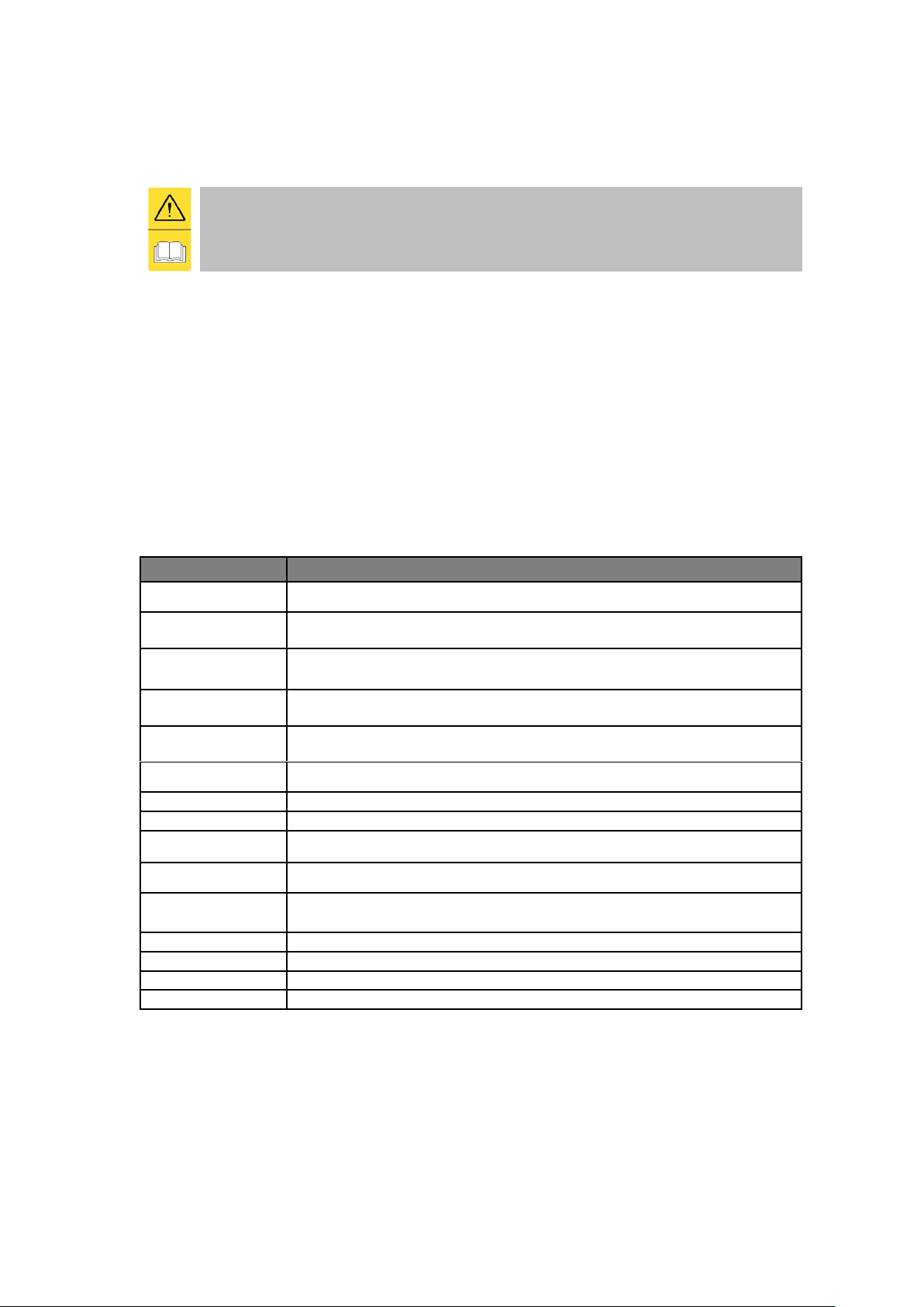
10.4.1 FLUE TERMINAL POSITIONS
Location
Description
HCB46CE – HCB61CE
HCB86CE
A
Directly below an opening, air brick, opening windows etc.
300
2000
B
Above an opening, air brick, opening windows etc.
300
1000
C
Horizontally to an opening, air brick, opening windows etc.
300
1000
D
Below a gutter or sanitary pipework
75
75
E
Below the eaves
200
200
F
Below a balcony or car port roof
200
200
G
From a vertical drain or soil pipe
150
150
H
From an internal or external corner
300
300
I
Above ground, roof or balcony level
300
300
J
From a surface facing the terminal
600
1000
K
From a terminal facing the terminal
1200
2000
L
From an opening in the car port (e.g. door, window) into the dwelling
1200
1200
M
Vertically from a terminal on the same wall
1500
1500
N
Horizontally from a terminal on the same wall
300
600
P
From a vertical structure on the roof
300
300
Q
Above intersection with the roof
300
300
10.4.2 FLUE TERMINAL POSITION MINIMUM DISTANCES

19
10.5 APPROVED FLUE SYSTEM
For Concentric and Twin pipe flue systems only the Lochinvar supplied M&G flue system must
be used
The approved flue system is not suitable for use external to the building. If external routes
cannot be avoided, a flue system manufacturer should be consulted to supply a suitable
alternative.
10.6 INSTALLATION PRECAUTIONS
The approved flue system is rated to 120C max. To prevent the exhaust temperature exceeding this, the
appliance is supplied with a flue gas temperature sensor.
This must be fitted during the installation of the flue system. Failure to do so may lead to
severe personal injury, death or substantial property damage.
The Boiler must not be operated unless the complete flue system is installed. This includes
the Boiler connections, concentric adaptor (if required) flue pipes, air ducts (if required) and
terminals. If discharging at low level, a suitable flue guard must be installed.
During assembly precaution should be taken to ensure that the internal sealing ring is seated
correctly.
Due to the close tolerances in the flue system, it may be necessary to use a twisting action to
fit the joints together. No lubrication other than water should be used.
20
10.1 ROOM SEALED (TYPE C) FLUE ASSEMBLY
In order to install the Herald boiler with a type C (room sealed) flue system a flue transition kit must first be installed,
this kit is used for both C13 (horizontal) and C33 (vertical) flue systems. The information in this paragraph describes
these flue transition kits and there installation.
10.2 INSTALLATION OF FLUE TRANSITION KIT TO HCB46CE-HCB61CE BOILERS
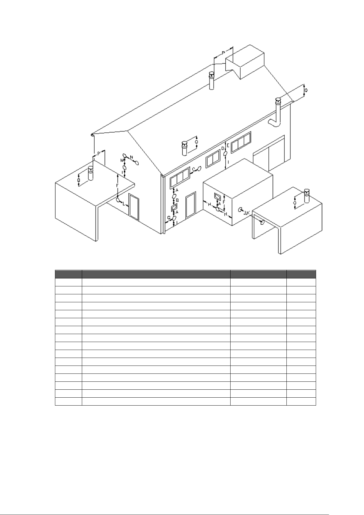
10.2.1 FLUE TRANSITION PARTS HCB46CE – HCB61CE
Depending upon the flue kit chosen either a vertical or a horizontal concentric terminal will be
included in the packaging with the transition kit, additional elbows, flue lengths etc. Further
items are available as ancillaries and may be required to complete the flue system. Additional
wall brackets may be required to ensure the flue system is stable.
For a full list of flue components supplied and optional parts to complete the system see the
herald flue guide available at www.lochinvar.ltd.uk
ITEM NUMBER
DESCRIPTION
HCB 46CE
HCB 61CE
1
90⁰ ELBOW
3 REQUIRED
3 REQUIRED
2
SAMPLING POINT
1 REQUIRED
1 REQUIRED
3
CONCENTRIC ADAPTOR
1 REQUIRED
1 REQUIRED
4
AIR INTAKE TRANSITION
1 REQUIRED
1 REQUIRED
5
80mm X 500mm LENGTH
CUT TO 270mm
CUT TO 270mm
10.2.2 HORIZONTAL CONCENTRIC FLUE TRANSITION PARTS HCB46CE – HCB61CE
21
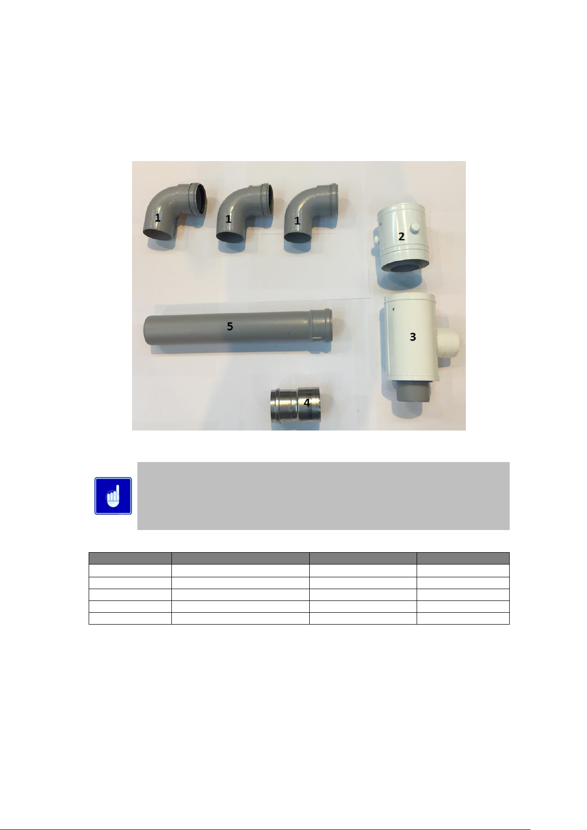
To install the flue connection to the HCB46CE – HCB61CE boilers the following procedure should be followed:
1. Check you have all items shown in Section 10.2.1
2. Check the flue temperature sensor (supplied with the boiler) is securely located into the hole on the exhaust
transition.
If the flue temperature sensor is not fitted, the flue gas may exceed the maximum temperature
rating of the flue and can lead to severe personal injury, death or substantial property damage.
3. Insert the air intake transition (Item 4) into the intake connection reducer (shown below) and tighten the worm
drive clip.
4. To the bottom (exhaust) connection of the concentric adaptor fit one of the 80mm 90 elbows, and then fit the
80mm x500mm flue pipe cut to length as in Section 10.2.2.
5. To the side (intake) connection of the concentric adaptor, fit the remaining 90 elbows.
6. Fit the Concentric adapter (item 3) to the exhaust flue pipe and air inlet elbows
7. Fit the flue gas test point (Item 2) and clamp using its locking band.
The completed transition kit should look like the photos shown below.
REAR VIEW TRANSITION KIT HCB46CE-HCB61CE
SIDE VIEW TRANSITION KIT HCB46CE-HCB61CE
10.2.3 TRANSITION KIT FITTED TO APPLIANCE
22
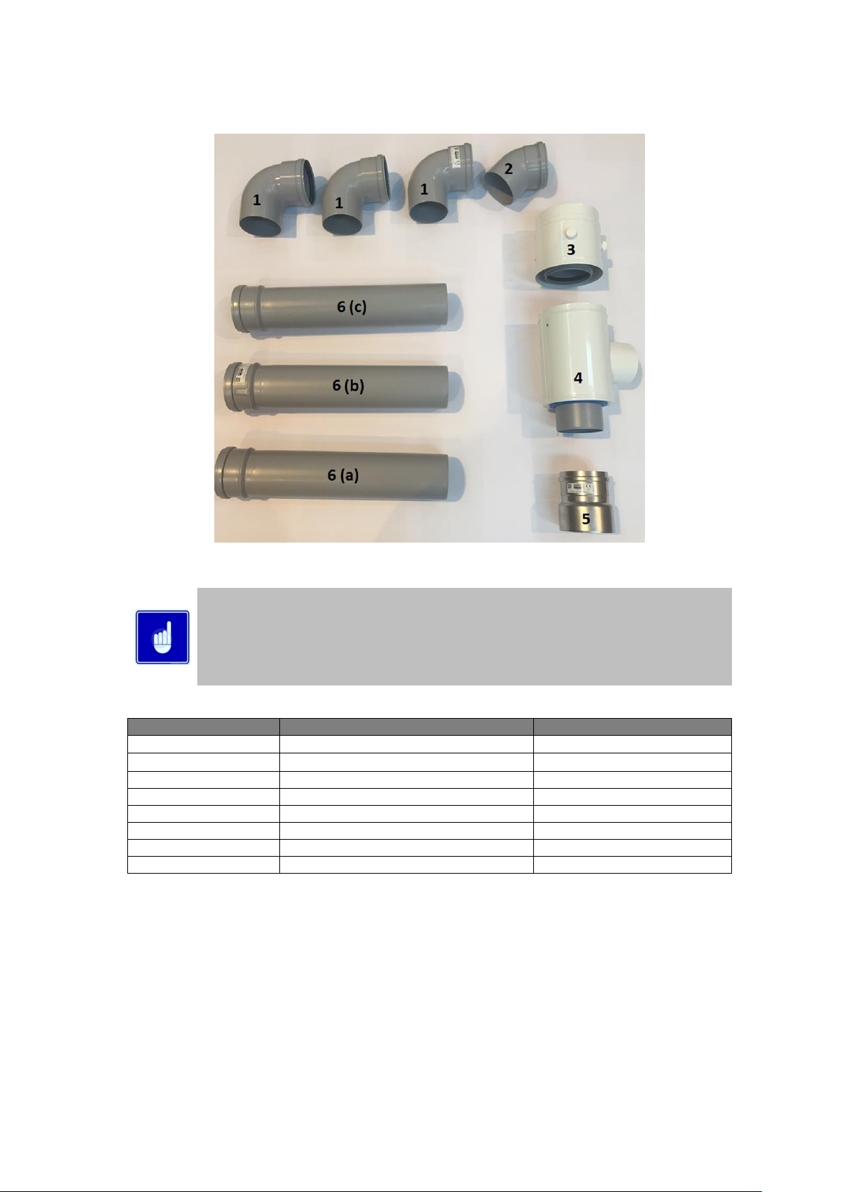
10.3 INSTALLATION OF TRANSITION KIT TO HCB86CE BOILER
10.3.1 FLUE TRANSITION PARTS HCB86CE
Depending upon the flue kit chosen either a vertical or horizontal concentric terminal will be
included in the packaging with the transition kit, additional elbows, flue lengths etc. Further
items are available as ancillaries and may be required to complete the flue system. Additional
wall brackets may be required to ensure the flue system is stable.
For a full list of flue components supplied and optional parts to complete the system see the
herald flue guide available at www.lochinvar.ltd.uk
ITEM NUMBER
DESCRIPTION
EKW/HCB 86
1
90⁰ ELBOW
3 REQUIRED
2
45⁰ ELBOW
1 REQUIRED
3
SAMPLING POINT
1 REQUIRED
4
CONCENTRIC ADAPTOR
1 REQUIRED
5
AIR INTAKE TRANSITION
1 REQUIRED
6 (a)
100mm X 500mm LENGTH
KEEP 500mm
6 (b)
100mm X 500mm LENGTH
CUT TO 330mm
6 (c)
100mm X 500mm LENGTH
CUT TO 330mm
10.3.2 HORIZONTAL CONCENTRIC FLUE TRANSITION PARTS HCB86CE
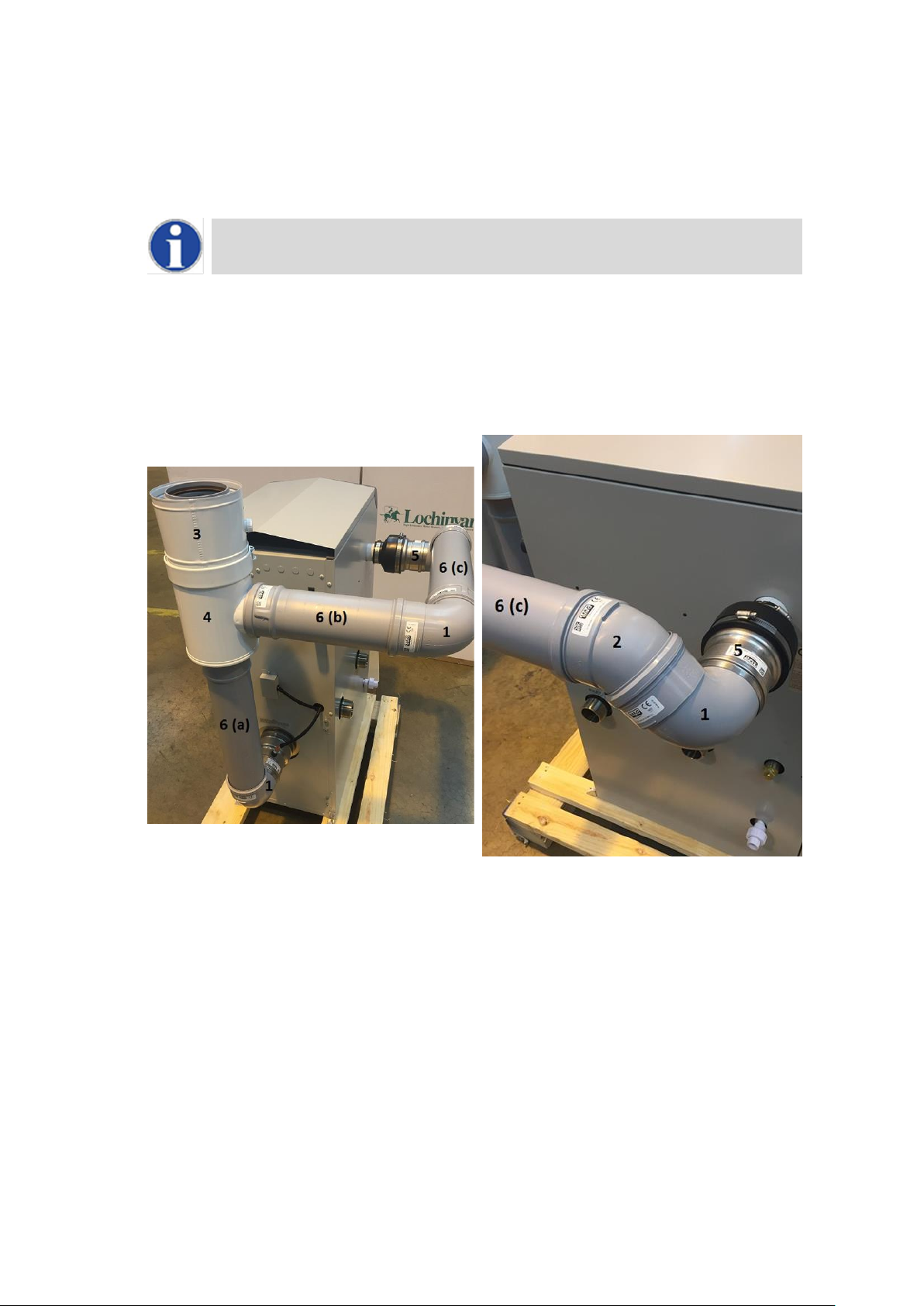
23
To install the flue connection to the HCB86CE boiler the following procedure should be followed:
1. Check you have all items shown in Section 10.3.2.
2. Check the flue temperature sensor (supplied with the boiler) is securely located into the hole on the exhaust
transition.
If the flue temperature sensor is not fitted, the flue gas may exceed the maximum temperature
rating of the flue and can lead to severe personal injury, death or substantial property damage.
3. Insert the air intake transition (Item 5) into the intake connection reducer and tighten the worm drive clip.
4. To the bottom (exhaust) connection of the concentric adaptor fit one of the 80mm 90 elbow, then fit the 80mm
x500mm flue pipe cut to length as in Section 10.3.2.
5. To the side (intake) connection of the concentric adaptor, fit the remaining 90 elbows.
6. Fit the Concentric adapter (item 3) to the exhaust flue pipe and air inlet elbows
7. Fit the flue gas test point (Item 2) and clamp using its locking band.
The completed transition kit should look like the photos shown below.
REAR VIEW TRANSITION KIT HCB86CE
SIDE VIEW TRANSITION KIT HCB86CE
10.3.3 TRANSITION KIT FITTED TO APPLIANCE
24
10.4 C13 CONCENTRIC HORIZONTAL FLUE SYSTEMS
Flue system specifications
MANUFACTURER MUELINK AND GROL (M&G)
TEMPERATURE CLASS T120
FLUE GAS MATERIAL PP
Each concentric horizontal flue kit includes the items shown in the tables below
Item No HBHF001
CONCENTRIC HORIZONTAL FLUE ASSEMBLY
MODELS HCB46CE,HCB61CE
COMPONENTS INCLUDED
Item No.
Description
Number
Quantity
M85291B
BEND 90° 80mm PP
1 3 M84471B
SAMPLING POINT Ø80/125mm PP
2 1 M75258B
CONCENTRIC ADAPTER TEE Ø80/80mm - Ø80/125mm PP
3 1 M75256B
AIR INLET TRANSITION Ø80mm ALU
4 1 M85271B
EXTENSION Ø80mm (500mm) PP CUT TO LENGTH
5 1 M84460B
CONCENTRIC BEND 90° Ø80/125mm PP
6
1
M86934B
CONCENTRIC HORIZONTAL TERMINAL Ø80/125mm PP (NO WALL PLATES)
7
1
M28925B
TERMINAL WALL PLATES (PAIR)
8
1
Item No HBHF002
CONCENTRIC HORIZONTAL FLUE ASSEMBLY
MODELS HCB86CE
COMPONENTS INCLUDED
Item No.
Description
Number
Quantity
M85181B
BEND 90° 100mm PP
1
3
M85182B
BEND 45° 100mm PP
2
1
M84421B
SAMPLING POINT Ø100/150mm PP
3
1
M75259B
CONCENTRIC ADAPTER TEE Ø100/100mm Ø100/150mm PP
4
1
M75257B
AIR INLET TRANSITION Ø100mm ALU
5
1
M85176B
EXTENSION Ø100mm (500mm) PP CUT TO LENGTH
6
3
M84412B
CONCENTRIC BEND 90° Ø100/150mm PP
7
1
LV310758B
CONCENTRIC HORIZONTAL TERMINAL Ø100/150mm PP
8
1
25
11.0 FLUE TERMINAL INSTALLATION
11.1 TYPE C
13
(HORIZONTAL ROOM SEALED)
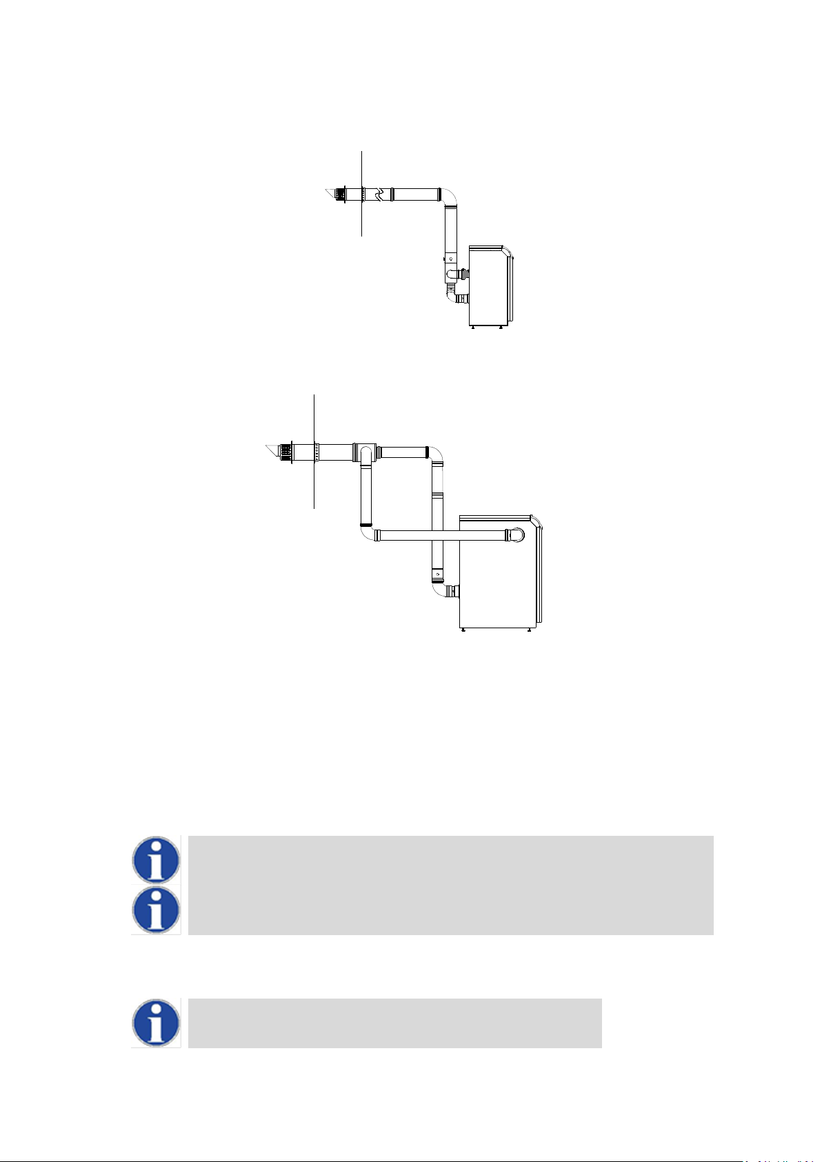
11.1.1 HORIZONTAL CONCENTRIC ROOM SEALED APPLICATION, MODELS HCB46CE-HCB61CE
11.1.2 HORIZONTAL CONCENTRIC ROOM SEALED APPLICATION, MODELS HCB86CE
When the boiler is installed as a Type C13 (Horizontal concentric) appliance, the flue system should be installed as
follows:
1. Determine the location of the flue terminal, taking into account minimum distances as detailed in Section
10.4.1 and the relevant British Standards.
2. Taking care to protect the appliance from debris and dust, drill a hole in the desired location. The diameter
of the hole should be no more than 10mm greater than the diameter of the air supply pipe of the terminal.
3. Determine the required length of the terminal and cut as necessary.
When determining the required length for the flue terminal, the outer wall plate or rosette
should be flush to the wall. (see 11.1.3 )
Once cut; remove all burrs and sharp edges
4. Insert the terminal into the drilled hole. The terminal section should be installed level or with a fall to outside
(Max. 10mm per metre) to prevent the ingress of water.
When inserting the terminal, ensure the air intake section is at the bottom.

26
5. Fill the void between the terminal and wall with water resistant sealant.
6. Fit the wall plates or rosette using appropriate fixings.
7. Install the remainder of the flue system working progressively away from the boiler supporting the pipes as
necessary.
11.1.3 HORIZONTAL TERMINAL INSTALLATION
11.2 FLUE TERMINAL GUARDING
If a horizontal flue terminal is to be fitted less than 2 metres from ground level or in a location where it can be touched
from a window, door or balcony, a terminal guard must be fitted.

27
11.3 C33 CONCENTRIC VERTICAL FLUE SYSTEMS
Flue system specifications
MANUFACTURER MUELINK AND GROL (M&G)
TEMPERATURE CLASS T120
FLUE GAS MATERIAL PP
Each concentric horizontal flue kit includes the items shown in the tables below
Item No HBVF001
CONCENTRIC VERTICAL FLUE ASSEMBLY
MODELS HCB46CE,HCB61CE
COMPONENTS INCLUDED
Item No.
Description
Number
Quantity
M85291B
BEND 90° 80mm PP
1
3
M84471B
SAMPLING POINT Ø80/125mm PP
2
1
M75258B
CONCENTRIC ADAPTER TEE Ø80/80mm - Ø80/125mm PP
3
1
M75256B
AIR INLET TRANSITION Ø80mm ALU
4
1
M85271B
EXTENSION Ø80mm (500mm) PP CUT TO LENGTH
5
1
LV310744B
CONCENTRIC EXTENSION Ø80/125mm(280-395mm) PP TELESCOPIC
6
1
M86864B
CONCENTRIC VERTICAL TERMINAL Ø80/125mm PP
7
1
Item No HBVF002
CONCENTRIC VERTICAL FLUE ASSEMBLY
MODELS HCB86CE
COMPONENTS INCLUDED
Item No.
Description
Number
Quantity
M85181B
BEND 90° 100mm PP
1
3
M85182B
BEND 45° 100mm PP
2
1
M84421B
SAMPLING POINT Ø100/150mm PP
3 1 M75259B
CONCENTRIC ADAPTER TEE Ø100/100mm Ø100/150mm PP
4
1
M75257B
AIR INLET TRANSITION Ø100mm ALU
5
1
M85176B
EXTENSION Ø100mm (500mm) PP CUT TO LENGTH
6
3
M84405B
CONCENTRIC EXTENSION Ø100/150 (500mm) PP CUT TO LENGTH
7
1
LV310754B
CONCENTRIC VERTICAL TERMINAL Ø100/150mm PP
8
1
28
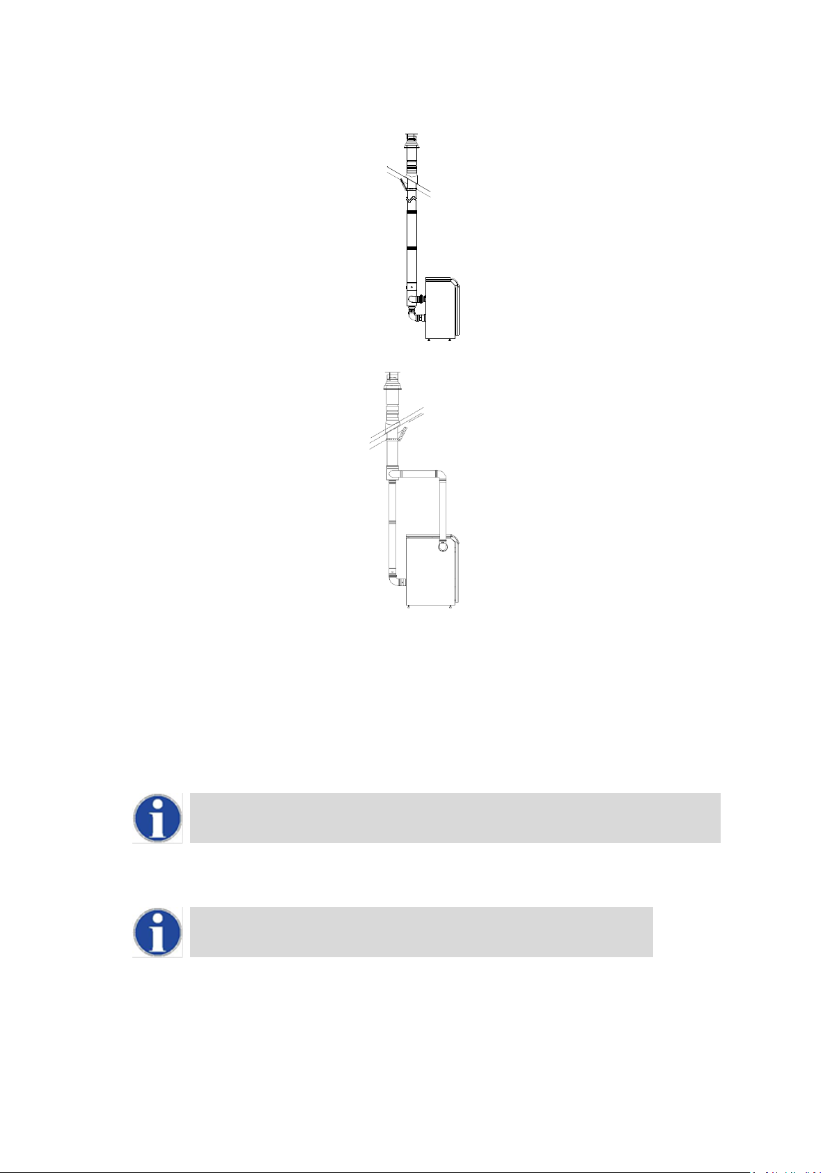
11.4 TYPE C
33
(VERTICAL ROOM SEALED)
11.4.1 VERTICAL CONCENTRIC ROOM SEALED APPLICATION, MODELS HCB46CE-HCB61CE
11.4.2 VERTICAL CONCENTRIC ROOM SEALED APPLICATION, MODELS HCB86CE
When the boiler is installed as a Type C33 (Vertical Concentric) appliance, the flue system should be installed as follows:
1. Confirm that the roof flashing is correct for the type of roof through which the terminal is to be installed. (See
11.4.3)
2. Determine the desired location for the flue terminal, taking into account minimum distances as detailed in
Section 10.4.1 and the relevant British Standards.
3. Taking care to protect the appliance from debris and dust, drill a hole in the desired location. The diameter
of the hole should be no more than 10mm greater than the diameter of the air supply pipe of the terminal.
The hole should be drilled from the outside to ensure that no damage is done to the roofing
material. Extra care should be taken to ensure that the hole is drilled vertically.
4. Install the roof flashing and secure as appropriate.
5. Carefully insert the roof terminal through the roof flashing and hole in the roof.
When inserting the roof terminal do not support or turn the terminal using the cap.
6. Ensure the terminal is vertical using a spirit level.
7. Fit the support bracket around the terminal and secure using appropriate fixings. Do not tighten the support
bracket
8. Install the remainder of the flue system working progressively away from the boiler supporting the pipes as
necessary.
9. Once the flue system is fully installed, tighten the clamp to secure the terminal in place.
 Loading...