

Lochinvar Armor 151, Outdoor Knight 286, Armor 801, Outdoor Knight 151, Outdoor Knight XL 400 Instructions Manual
...Page 1
MODB-I-O_100161545_2000014822_Rev M
MODBUS AND BACNET
COMMUNICATION
INSTRUCTIONS
Models:
Knight 81 - 286, Knight XL 400 - 801,
Armor 151 - 801, Outdoor Knight 151
- 286, Outdoor Knight XL 400 - 801,
Outdoor Armor 151 - 801,
AQUAS 400 - 801, FTXL 400 - 850,
Wall Mount 51 - 211, Wall Hung 55 -
399, and Wall Mount Armor 125 - 200
WARNING
is manual must only be used by a
quali ed heating installer / service
technician. Read all instructions,
including this manual, the Installation
and Operation Manual, and the Service
Manual, before installing. Perform
steps in the order given. Failure to
comply could result in severe personal
injury, death, or substantial property
damage.
Save this manual for future reference.
Page 2

Contents
1. INTRODUCTION
Defi nitions .................................................................... 2
Minimum System Requirements .................................. 2
2. INSTALLATION
Wall Mount, Armor, Knight and Knight XL, Outdoor
Armor, Outdoor Knight, and Outdoor Knight XL........ 3-4
FTXL ............................................................................ 5
Wall Hung .................................................................... 6
3. MODBUS CONFIGURATION
Addressing ................................................................... 7
Timing Specifi cations ................................................... 8
Parity ............................................................................ 8
Data Transmission Mode ............................................. 8
ModBus Board Diagnostics ......................................... 8
Internal Faults ......................................................... 8
ModBus Function Set .................................................. 9
ModBus Exception Codes ........................................... 10
4. MODBUS MEMORY MAP
Primary Data Tables .................................................... 11
Memory Map............................................................11-12
Input Registers .......................................................12
Holding Registers ................................................... 12
Confi guration Bits......................................................... 12
5. BACNET CONFIGURATION ....................................... 13
Addressing ................................................................... 13
Timing Specifi cations ...................................................14
Communication Board Diagnostics ............................. 14
Internal Faults ......................................................... 14
6. BACNET MEMORY MAP
Primary Data Tables .................................................... 15
Crest Boiler Memory Map........................................15-16
Input Registers ............................................................15
Holding Registers ................................................... 16
7. WIRING REQUIREMENTS
Physical Wiring ............................................................ 17
Control Inputs/Outputs............................................ 18-19
Control Location.......................................................20-21
Typical Boiler/Water Heater System Wiring................ 22
8. UNIT OPERATION
Unit Operation with ModBus
Communications ..................................................... 23-27
9. TROUBLESHOOTING ........................................... 28-29
10. DIAGRAMS
Ladder & Wiring Diagrams ..................................... 30-39
Revision Notes ................................................... Back Cover
1 Introduction
e information contained in this manual provides general guidelines for the implementation of ModBus and BACnet
communication with the Lochinvar Armor water heaters (151 - 801), Wall Mount Armor (125-200), Knight (81-286), Knight
XL (400 - 801), Outdoor Knight (151-286), Outdoor KnightXL (400-801), Outdoor Armor (151-801), Wall Mount (51 - 211),
and Wall Hung (55 - 399) boilers.
All ModBus networks are implemented utilizing a master-slave arrangement where all boilers/water heaters are slaves and
the master is a building automation system capable of communicating over a RS-485 half duplex serial connection. BACnet
networks are implemented using a token passing process where multiple masters and slaves share a common RS-485 bus. e
Lochinvar BACnet interface is a master only.
Defi nitions
Abbreviation or Acronym Meaning
ASCII American Standard Code for Information Interchange
BACnet A data communication protocol for Building Automation and Control Networks
BAS Building Automation System
Baud (Baud Rate) Number of data bits transmitted per second (bps)
EMS Energy Management System
FDX Full-Duplex
HDX Half-Duplex
Hex Hexadecimal Number (0 - 9, A - F)
I/O Box Input/Output (I/O)
LSB Least Signifi cant Byte
ModBus A serial, half-duplex data transmission protocol developed by AEG Modicon
MSB Most Signifi cant Byte
RS232
RS485 A standard for serial transmission of data based on the RS-485 Standard
RTU Remote Terminal Unit
A standard for serial, full-duplex (FDX) transmission of data based on the RS232
Standard
Minimum System Requirements
• BAS system or computer with a serial or USB port
with a converter to RS-485 half duplex.
• Unit equipped with communication board.
• Shielded twisted pair communication cable.
Page 3
2 Installation
ModBus and BACnet Communication Instructions
Installation procedure - for Models WB,
WA, AW, KB, OA, OK and KBX
1. Turn OFF the main electrical power to the appliance.
2. Turn OFF the main manual gas shuto to the appliance.
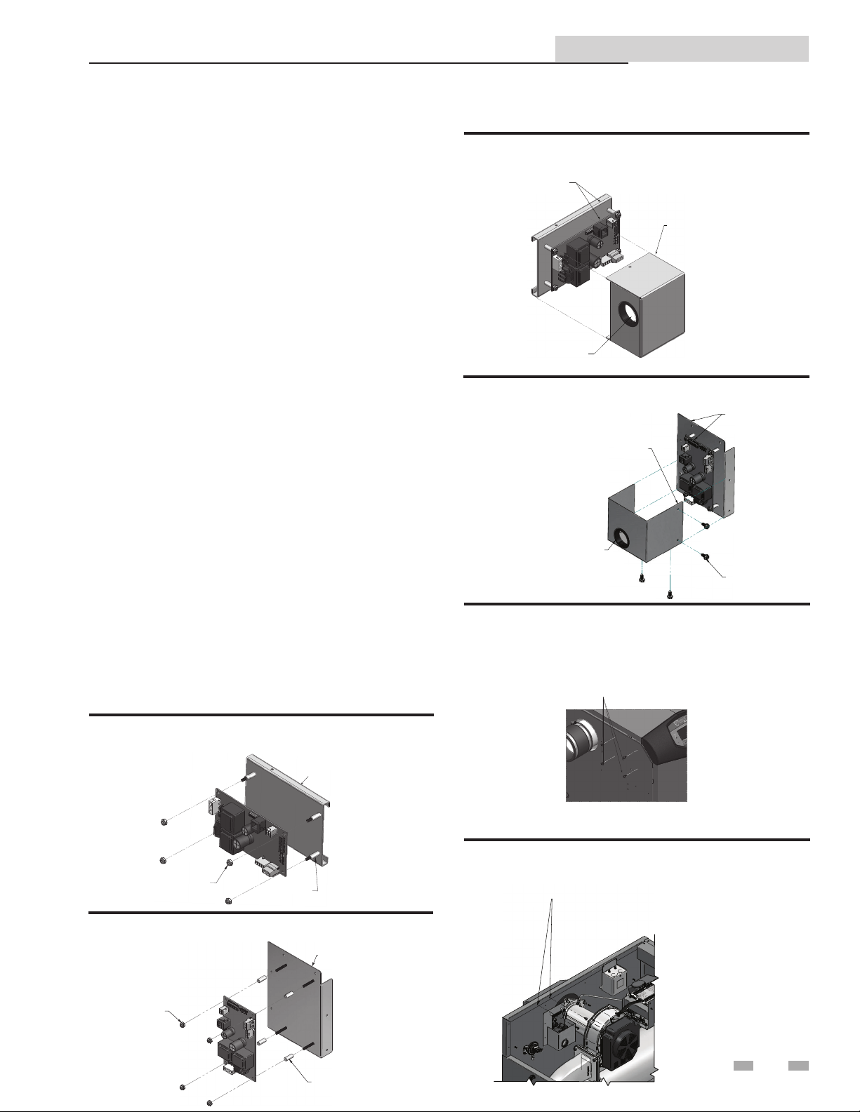
3. Assemble the communication control board to the sheet
metal base as shown in FIG. 2-1a and 2-1b, depending on
model.
4. Connect the power harness from the appliance to the
communication board through the sheet metal cover
hole (see FIG. 2-2a and 2-2b, depending on model).
5. Using the two (2) sheet metal screws provided in the kit,
attach the pre-painted sheet metal cover over the
Communication board for protection from line voltage
(FIG. 2-2a and 2-2b, depending on model).
6. Locate the pilot holes on the side of the jacket (le side if
AW/KB/KXL or right side if WB/WA), using the sheet
metal screws provided in the kit, mount the
communication board assembly to the appliance (FIG.
2-3a and 2-3b, depending on model).
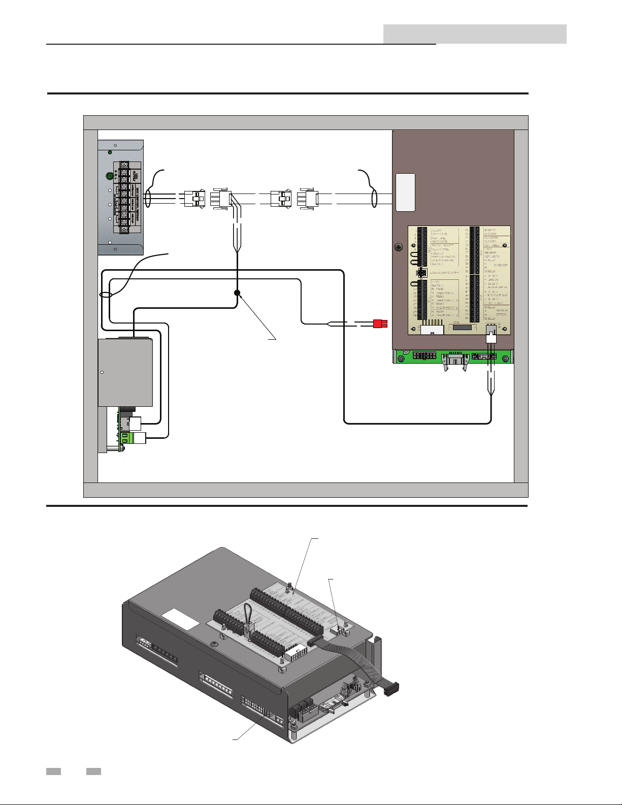
Wiring
7. Disconnect power to the transformer by removing
connection “B”, see FIG. 2-4, page 4.
8. Connect A, C, D, and B (FIG. 2-4).
9. Connect the communication board to the control board
of the appliance (see FIG. 2-5 on page 4).
10. Turn on the main electrical power and the main manual
gas shuto to the appliance.
11. Con gure the control board and unit controls per this
manual and resume operation.
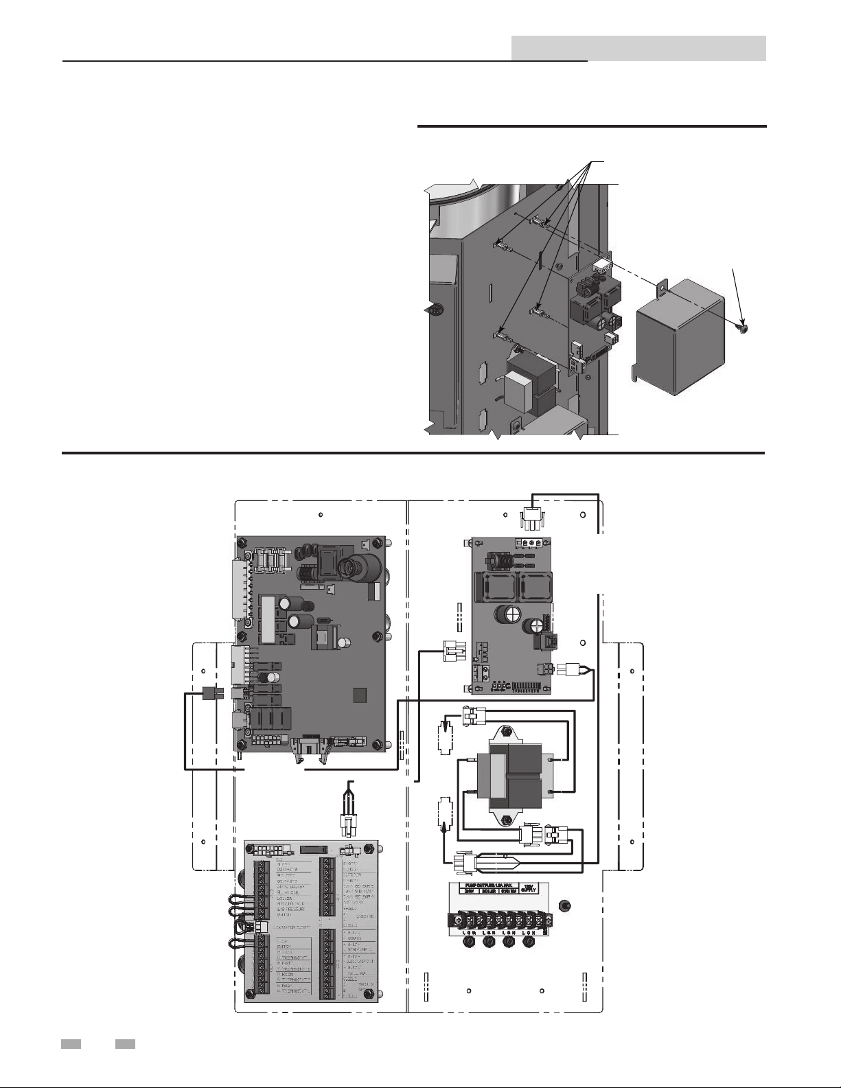
Figure 2-2a_Attach Cover to Communication Board for
Models WB, WA, AW, KB and KBX
MODBUS
ASSEMBLY
MOUNT PRE-PAINTED
SHEET METAL COVER
OVER THE MODBUS
ASSEMBLY FOR PROTECTION
FROM LINE VOLTAGE
ATTACH POWER HARNESS
TO MODBUS THROUGH
SHEET METAL COVER HOLE
Figure 2-2b_Attach Cover to Communication Board
for Models OA and OK
MOUNT PRE-PAINTED
SHEET METAL COVER OVER
THE MODBUS ASSEMBLY FOR
PROTECTION FROM LINE VOLTAGE
ATTACH POW ER HARNESS
TO MODBUS THROUGH
SHEET METAL COVER HOLE
MODBUS
ASSEMBLY
IMG00566
BLT7404 [X4]
Figure 2-3a_Mount Communication board to Unit for
Models WB, WA, AW, KB and KBX
- LOCATE THE PILOT HOLES
- USING THE 4 SHEET METAL SCREWS
PROVIDED IN THE KIT MOUNT THE MODBUS
ASSEMBLY TO THE UNIT
(SIDE DEPENDENT ON MODEL)
Figure 2-1a_Assemble Communication Board for
Models WB, WA, AW, KB and KBX
SHEET METAL BASE
JKB40095
BLT2007 [X4]
BLT7068 [X4]
Figure 2-1b_Assemble Communication Board for
Models OA and OK
BLT2007
[X4]
SHEET METAL
BASE (JKB40265)
IMG00565
BLT7068 [X4]
NOTE: KB/KXL/AW - MOUNT MODBUS ASSEMBLY TO THE LEFT SIDE OFTHE
JACKET. WB/WA - MOUNT MODBUS ASSEMBLY TO THE RIGHT SIDE OF THE JACKET.
Figure 2-3b_Mount Communication board to Unit for
Models OA and OK
- LOCATE THE PILOT HOLES
- USING THE (2) SHEET METAL SCREWS PROVIDED
IN THE KIT MOUNT THE MODBUS ASSEMBLY TO THE UNIT
(SIDE AND ORIENTATION DEPENDENT ON MODEL /
VERTICAL ORIENTATION SHOWN)
NOTE: OA/OK151 MOUNT MODBUS ASSEMBLY TO THE RIGHT SIDE JACKET FLANGE
OA/OK400-501 MOUNT MODBUS ASSEMBLY IN HORIZONTAL ORIENTATION
IMG00567
3
Page 4
ModBus and BACnet Communication Instructions
2 Installation
Figure 2-4_Harness Connections_WB, WA, AW, KB, KBX, OA, and OK models
FROM POWER
HARNESS
A
B
G
W
ROUTE THROUGH
JACKET HARNESS
CLIPS
USE SUPPLIED CABLE TIE
TO CONNECT MODBUS POWER
HARNESS TO BLOWER POWER
WIRES (RED, WHITE, GREEN)
TO TRANSFORMER
D
C
B
W
WGB
B
B
W
GY
G
R
BL
G
Figure 2-5_Connect Communication Board to Control Board
CONNECT TO
CONTROL BOARD
FROM COMMUNICATION
BOARD*
4
*HARNESSES CAN ONLY BE CONNECTED ONE WAY.
LOW VOLTAGE
CONNECTION BOARD
CONNECT TO
CONNECTION BOARD
FROM COMMUNICATION
BOARD*
Page 5
2 Installation (continued)
ModBus installation procedure - for FTXL Models
ModBus and BACnet Communication Instructions
Figure 2-6a_Assemble ModBus Control Board for FTXL
2X RIVET
4X LOCKNUT
2X CLIP
4X ALUMINUM
SPACER
IMG01107
1. Turn OFF the main electrical power to the appliance.
2. Turn OFF the main manual gas shuto to the appliance.
3. Assemble the ModBus control board and provided cable
clamps to the control panel as shown in FIG. 2-6a.
4. Connect the ModBus power, control board and
connection board wiring harnesses. Secure the wiring
with the provided cable clips and route it through the
bottom of the control panel. Perform the wiring
connections referencing FIG.’s 2-6b and 2-6c.
5. Turn ON the main electrical power to the appliance.
6. Con gure the control board and unit controls per this
manual and resume operation.
Figure 2-6b_Secure Control Board to FTXL Unit
SECURE CONNECTION
BOARD W/ 5X CLIPS
MODBUS
POWER HARNESS
UNIT
POWER HARNESS
TRANSFORMER
PRIMARY 120V
IMG01106
Figure 2-6c_Perform Wiring Connections for FTXL
LOW VOLTAGE CONNECTION BOARD
SECURE HARNESS
W/ 3X CLIPS
CONNECTION BOARD /
MODBUS HARNESS
MAIN CONTROL BOARD
UNIT POWER HARNESS
MODBUS
MODBUS
POWER HARNESS
PRIMARY
120V
SECURE HARNESS
W/ 2X CLIPS
IMG01105
5
Page 6
2 Installation
ModBus and BACnet Communication Instructions
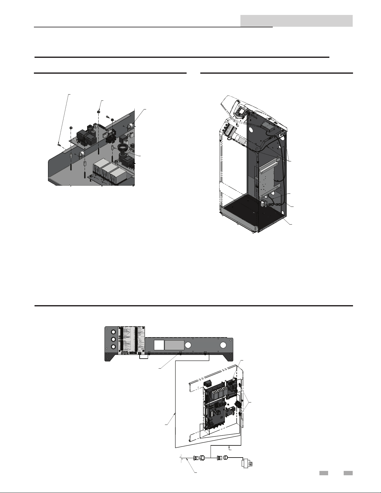
Installation Procedure - for WH Models
1. Turn OFF the main electrical power to the appliance.
2. Turn OFF the main manual gas shuto to the appliance.
3. To assemble the communication board to the sheet metal,
insert four (4) stando s into the front access panel
(FIG. 2-6).
4. Place the communication board onto the stando s
installed in Step 3. Use the screw (provided in kit) to
secure the control panel cover (FIG. 2-6).
5. Connect the wire harnesses (100172824 , 100172826 and
100172828) from the appliance to the communication
board following the diagram shown in FIG. 2-7.
6. Turn on the main electrical power and the main manual
gas shuto to the appliance.
7. Con gure the communication board and unit controls
per this manual and resume operation.
Figure 2-7_Harness Connections_WH
Figure 2-6_Assemble Communication Board_WH
INSERT
STANDOFFS
USE SCREW TO
SECURE COVER
TO FRONT PANEL
(WRE20075)
(WRE20073)
G
R
B
L
(WRE20077)
G
Y
G
W
B
W
W
G
B
B
6
Page 7
ModBus and BACnet Communication Instructions
3 ModBus Confi guration
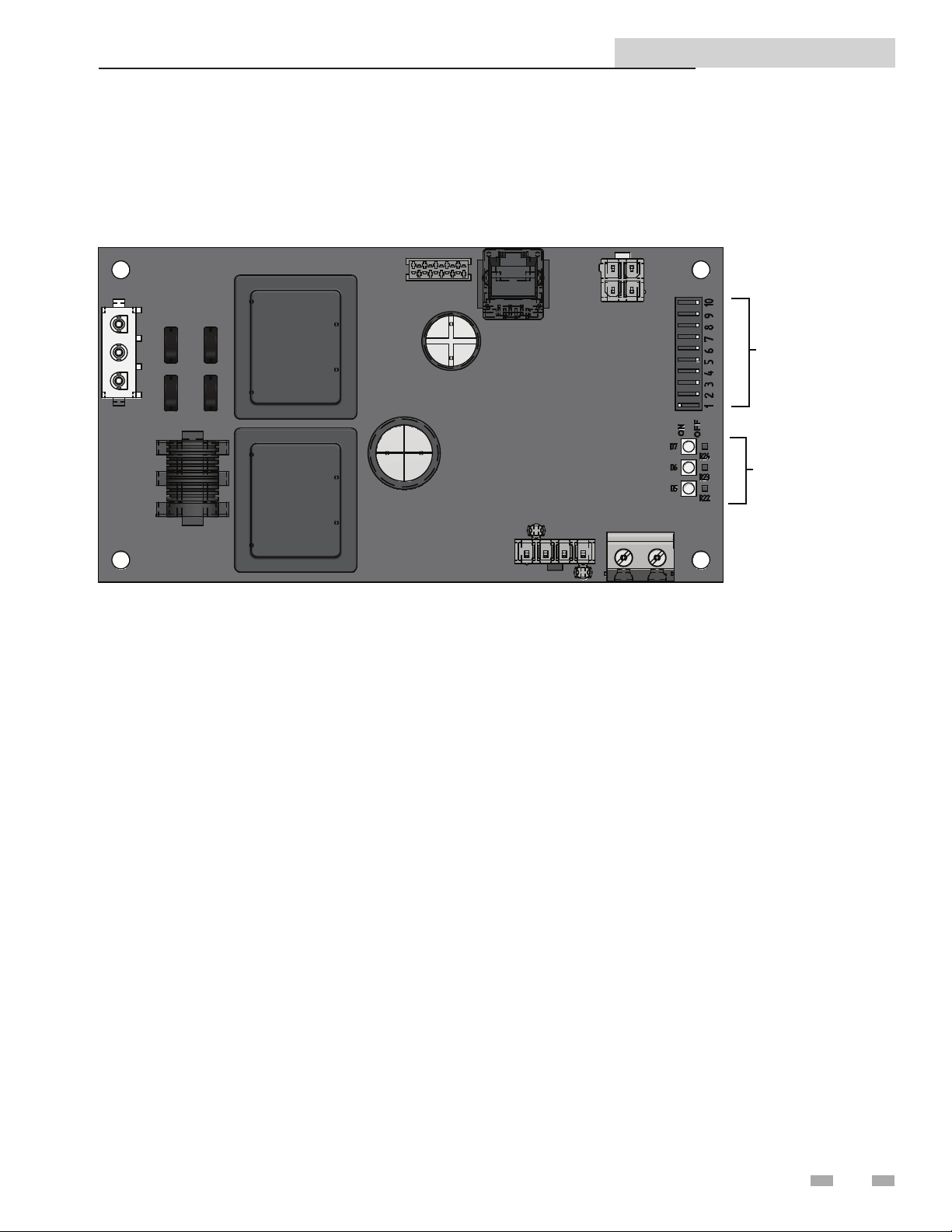
e ModBus communication board is equipped with a set of ten dip switches that are used to set the board con guration
(address, baud rate, and parity settings). e rst eight are used to set the address of each board. e ninth is baud rate. e
tenth is parity.
Figure 3-1_ModBus Communication Board
DIP SWITCHES
LED’S
Addressing
e ModBus addressing space is comprised of 256 di erent
addresses.
• 0 is reserved for broadcast messages from the master
device
• 1 - 247 are free to use for each unique device
• 248 - 255 are reserved
To set the ModBus address the dip switches can be set in
either the 0 position or the 1 position. For switches set to
the 1 position their value will be added together to determine
the address.
Each switch set to the 1 position has the following value:
Dip switch 1 = 1
Dip switch 2 = 2
Dip switch 3 = 4
Dip switch 4 = 8
Dip switch 5 = 16
Dip switch 6 = 32
Dip switch 7 = 64
Dip switch 8 = 128
Any dip switch set to 0 has a value equal to 0.
Example:
To set the address of the ModBus board to 50, dip switches 2, 5,
and 6 have to be set to the 1 position. e address is determined
by adding the values of all the dip switches together.
Address = Value of Dip switch 1 + Value of Dip switch 2 +
Value of Dip switch 3 + Value of Dip switch 4 + Value of Dip
switch 5 + Value of Dip switch 6 + Value of Dip switch 7 +
Value of Dip switch 8
In this example:
Address = 0 + 2 + 0 + 0 + 16 + 32 + 0 + 0 = 50
7
Page 8

3 ModBus Confi guration
ModBus and BACnet Communication Instructions
Timing Specifi cations
e baud rate for the ModBus board is selectable with Dip
switch #9.
1 = 19200 bps
0 = 9600 bps
Each message is started by at least 3.5 character times of
silence. e maximum delay between frames is 1.5 character
times.
When the system temperature, tank temperature, and/or
0-10V BMS voltage is provided by the BAS to the boiler, it
is critical that the values be updated every few seconds. If
the boiler does not receive updated values within a timeout
period (installer adjustable), the control will revert to using its
own readings (if connected). e timeout is programmable
as follows:
NOTICE
1. Press and hold the LEFT SELECT [MENU] key for 5
seconds.
2. Enter installer code - 5309.
3. Scroll down and select [CONTROL MODES].
4. Scroll down and select [MODBUS T/O].
5. Scroll to desired time. Press the RIGHT SELECT [SAVE]
key.
Please note that the brackets ([]) denote
screen status.
Data Transmission Mode
Many ModBus bus master devices can be con gured to
transmit data in either ModBus RTU or ModBus ASCII modes.
Since RTU messages can be formatted to use fewer data bits and
are therefore more e cient, RTU has been chosen to be used
with all Lochinvar ModBus communication. Please ensure that
the master device is transmitting ModBus RTU.
ModBus Board Diagnostics
e ModBus board is equipped with three LED’s for visual
diagnostics: Two yellow LED’s and one green. One yellow LED
(D5) is used to indicate transmission of data. e other yellow
LED (D6) is used to indicate reception of data. e green LED
(D7) is used to show internal faults.
Internal Faults:
Normal Operation = 1 second bright, 1 second dim
Controller Fault = Continuously on
No Burner Control Communication = 0.5 seconds on, 1.5
seconds o
No ModBus Communication = 1.5 seconds on, 0.5 seconds
o
ModBus Communication
e ModBus communication commands and exception codes
that are supported by the ModBus communication board can
be found on pages 8 and 9 of this manual.
e timeout is adjustable between 5 and 120 seconds. e
default timeout is 10 seconds.
When the BAS is not providing any of these values, but
is still controlling the boiler (such as providing an enable
command), the BAS must refresh these commands at least
every 4 minutes. If the commands are not refreshed, the
boiler will revert to operating based on its own inputs.
Parity
Parity is set by the position of Dip switch #10.
0 = No Parity
1 = Even Parity
If No Parity is selected there will be two stop bits, otherwise
there will be one.
8
Page 9

3 ModBus Confi guration (continued)
ModBus Function Set
ModBus and BACnet Communication Instructions
Function Sub Function
HEX Description
Dec HEX Dec
1 01 Read Coil Status
2 02 Read Input Status
3 03 Read Holding Registers
4 04 Read Input Registers
5 05 Force Single Coil
6 06 Preset Single Register
7 07 Read Exception Status
8 08 0 00 Diagnostic - Return Query Data
1 01 Diagnostic - Restart Communication
2 02 Diagnostic - Return Diagnostic Register
4 04 Diagnostic - Force Listen Mode
10 0A
11 0B Diagnostic - Return Bus Message Count
Diagnostic - Clear Counters and Diagnostic
Registers
12 0C Diagnostic - Bus Communication Error Count
13 0D Diagnostic - Bus Exception Error Count
14 0E Diagnostic - Return Slave Message Count
15 0F Diagnostic - Return Communication Error Count
16 10 Diagnostic - Return Slave NAK Count
17 11 Diagnostic - Return Slave Busy Count
18 12 Diagnostic - Return Bus Character Overrun Count
20 14 Diagnostic - Clear Overrun Counter and Flag
11 0B Get Communication Event Counter
12 0C Get Communication Event Log
15 0F Write Multiple Coils
16 10 Write Multiple Registers
17 11 Report Slave ID
23 17 Read / Write Multiple Registers
9
Page 10

ModBus and BACnet Communication Instructions
3 ModBus Confi guration
ModBus Exception Codes
MODBUS Exception Codes
Code Name Meaning
The function code received in the query is not an allowable action for the server
(or slave). This may be because the function code is only applicable to newer
01 ILLEGAL FUNCTION
02 ILLEGAL DATA ADDRESS
devices, and was not implemented in the unit selected. It could also indicate that
the server (or slave) is in the wrong state to process a request of this type, for
example because it is unconfi gured and is being asked to return register values.
The data address received in the query is not an allowable address for the
server (or slave). More specifi cally, the combination of reference number and
transfer length is invalid. For a controller with 100 registers, the PDU addresses
the fi rst register as 0, and the last one as 99. If a request is submitted with a
starting register address of 96 and a quantity of registers of 4, then this request
will successfully operate (address-wise at least) on registers 96, 97, 98, 99. If
a request is submitted with a starting register address of 96 and a quantity of
registers of 5, then this request will fail with Exception Code 0x02 “Illegal Data
Address” since it attempts to operate on registers 96, 97, 98, 99 and 100, and
there is no register with address 100.
03 ILLEGAL DATA VALUE
04 SLAVE DEVICE FAILURE
05 ACKNOWLEDGE
06 SLAVE DEVICE BUSY
08 MEMORY PARITY ERROR
A value contained in the query data fi eld is not an allowable value for server
(or slave). This indicates a fault in the structure of the remainder of a complex
request, such as that the implied length is incorrect. It specifi cally does NOT
mean that a data item submitted for storage in a register has a value outside the
expectation of the application program, since the MODBUS protocol is unaware of
the signifi cance of any particular value of any particular register.
An unrecoverable error occurred while the server (or slave) was attempting to
perform the requested action.
Specialized use in conjunction with programming commands. The server
(or slave) has accepted the request and is processing it, but a long duration of
time will be required to do so. This response is returned to prevent a timeout error
from occurring in the client (or master). The client (or master) can next issue a Poll
Program Complete message to determine if processing is completed.
Specialized use in conjunction with programming commands. The server
(or slave) is engaged in processing a long -- duration program command. The
client (or master) should re-transmit the message later when the server (or slave)
is free.
Specialized use in conjunction with function codes 20 and 21 and reference type
6, to indicate that the extended fi le area failed to pass a consistency check. The
server (or slave) attempted to read record fi le, but detected a parity error in the
memory. The client (or master) can retry the request, but service may be required
on the server (or slave) device.
0A GATEWAY PATH UNAVAILABLE
0B
GATEWAY TARGET DEVICE
FAILED TO RESPOND
10
Specialized use in conjunction with gateways, indicates that the gateway was
unable to allocate an internal communication path from the input port to the
output port for processing as the request. Usually means that the gateway is
misconfi gured or overloaded.
Specialized use in conjunction with gateways, indicates that no response was
obtained from the target device. Usually means that the device is not present on
the network.
Page 11
ModBus and BACnet Communication Instructions
4 ModBus Memory Map
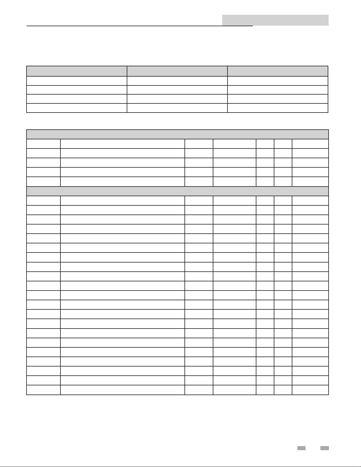
Primary Data Tables
Table Data Type Read / Write
Discrete Inputs Single Bit Read Only
Coils Single Bit Read / Write
Input Registers 16-Bit Word Read Only
Holding Registers 16 Bit Word Read / Write
Memory Map
Coils
Address Description Default Unit Min. Max. Resolution
00001 Room Thermostat 1 0 1=ON / 0=OFF 0 1 1
00002 Room Thermostat 2 0 1=ON / 0=OFF 0 1 1
00003 Room Thermostat 3 0 1=ON / 0=OFF 0 1 1
00005 Tank Thermostat 0 1=ON / 0=OFF 0 1 1
Discrete Inputs
10002 Flow Switch 0 1=ON / 0=OFF 0 1 1
10003 Gas Pressure Switch 0 1=ON / 0=OFF 0 1 1
10004 Louver Proving Switch 0 1=ON / 0=OFF 0 1 1
10005 Air Pressure Switch 0 1=ON / 0=OFF 0 1 1
10006 Blocked Drain Switch 0 1=ON / 0=OFF 0 1 1
10007 Auto Reset High Limit 0 1=ON / 0=OFF 0 1 1
10008 Flame 0 1=ON / 0=OFF 0 1 1
10009 Room Thermostat 1 0 1=ON / 0=OFF 0 1 1
10010 Tank Thermostat 0 1=ON / 0=OFF 0 1 1
10024 Room Thermostat 2 0 1=ON / 0=OFF 0 1 1
10033 Run-time Contacts 0 1=ON / 0=OFF 0 1 1
10034 Alarm Contacts 0 1=ON / 0=OFF 0 1 1
10035 CH Pump 0 1=ON / 0=OFF 0 1 1
10036 DHW Pump 0 1=ON / 0=OFF 0 1 1
10037 Louver Relay 0 1=ON / 0=OFF 0 1 1
10038 Gas Valve 0 1=ON / 0=OFF 0 1 1
10039 System Pump 0 1=ON / 0=OFF 0 1 1
10044 DHW Recirculation Pump 0 1=ON / 0=OFF 0 1 1
11
Page 12

ModBus and BACnet Communication Instructions
4 ModBus Memory Map
Memory Map
Input Registers
Address Description Default Unit Min. Max. Resolution
30001 Discrete Inputs 1 - 16 0 HEX 0 65535 1
30002 Discrete Inputs 17 - 32 0 HEX 0 65535 1
30003 Discrete Inputs 33 - 48 0 HEX 0 65535 1
30004 System / Cascade Setpoint 0 Degrees Celsius 0 130 0,5
30005 System Pump Speed 0 % 0 100 1
30006 Cascade Total Power 0 % 100 800 1
30007 Cascade Current Power 0 % 0 800 1
30008 Outlet Setpoint 0 Degrees Celsius 0 130 0,5
30009 Outlet Temperature 0 Degrees Celsius 0 130 0,1
30010 Inlet Temperature 0 Degrees Celsius -20 130 0,1
30011 Flue Temperature 0 Degrees Celsius -20 130 0,1
30012 Firing Rate 0 % 0 100 1
30013 Boiler Pump Speed 0 % 0 100 1
30014 Boiler Status Code 0 HEX 0 65535 1
30015 Boiler Blocking Code 0 HEX 0 65535 1
30016 Boiler Lockout Code 0 HEX 0 65535 1
Holding Registers
40001 Confi guration 0 NA 0 65535 1
40002 Coils 0 NA 0 65535 1
40003
40004 Tank Setpoint 0 Degrees Celsius 0 87,5 0,5
40005 Tank Temperature 0 Degrees Celsius -20 130 0,1
40006 Outdoor Temperature 0 Degrees Celsius -40 60 0,1
40007 System Supply Temperature 0 Degrees Celsius -20 130 0,1
40008 DHW Recirculation Temperature 0 Degrees Celsius -20 130 0,1
0-10 Volt Input / Rate Command / Setpoint
Command
0 % 0 100 1
Confi guration Bits
Address 40001 contains con guration bits sent from the BAS to the appliance. ese bits tell the boiler/water heater to use its
own internal inputs, or inputs from the BAS. When a bit is set to 1, the boiler/water heater will ignore the corresponding value
contained internally, and expect the BAS to write that value into the Holding Registers. e con guration bits are as follows:
Bit 0 (LSB): Boiler Enable
Bit 1: Tank ermostat
Bit 2: Rate Command / 10 - 10V Input / Setpoint Command
Bit 3: Tank Setpoint
Bit 4: System Supply Temperature
Bit 5: Outdoor Temperature
Bit 6: Tank Temperature
Bit 7: System Return Temperature
Bit 8 - 15: Not Used (Default = 0)
12
Page 13

ModBus and BACnet Communication Instructions
Modbus Instructions
5 BACNET Confi guration
e BACnet communication board is equipped with a set of ten dip switches that are used to set the board con guration (address
and baud rate). e rst eight are used to set the address of each board. e ninth and tenth are baud rate.
Figure 5-1_Communication Board
DIP SWITCHES
LED’S
Addressing
e BACnet local addressing space is comprised of 256
di erent addresses.
• 255 is reserved for broadcast messages from a
master device.
• 128 - 254 are free to use for slave devices only.
• 0 - 127 are free to use for master or slave devices.
Since the BACnet communication board is a BACnet master,
address 127 is the highest address that can be used.
To set the BACnet local address, the dip switches can be set
in either the 0 position or the 1 position. For switches set to
the 1 position their value will be added together to determine
the address.
Each switch set to the 1 position has the following value:
Dip switch 1 = 1
Dip switch 2 = 2
Dip switch 3 = 4
Dip switch 4 = 8
Dip switch 5 = 16
Dip switch 6 = 32
Dip switch 7 = 64
Dip switch 8 = 128
Any dip switch set to 0 has a value equal to 0.
Example:
To set the address of the BACnet board to 50, dip switches
2, 5, and 6 have to be set to the 1 position. e address
is determined by adding the values of all the dip switches
together.
Address = Value of Dip switch 1 + Value of Dip switch 2 +
Value of Dip switch 3 + Value of Dip switch 4 + Value of Dip
switch 5 + Value of Dip switch 6 + Value of Dip switch 7 +
Value of Dip switch 8
In this example:
Address = 0 + 2 + 0 + 0 + 16 + 32 + 0 + 0 = 50
e BACnet Device Instance is calculated by adding the
BACnet local address to 600000. Using the above example, the
Device Instance will be:
Device Instance = 600000 + 50 = 600050
e base address (600000 in this example) is model dependant
and can be changed by the integrator. It can be set to any value
between 0 and 4194048. e resulting device instance will be
this value + the local address, as before. Once the base address
is changed, it can be reset back to the default base address
(600000 in this example) using the following procedure:
1. Turn OFF power to the interface board.
2. Set Dip switches 1 - 8 to the 1 position.
3. Turn ON power to the interface board.
4. A er a few seconds, turn OFF power to the interface board.
5. Set Dip switches 1 - 7 to the desired local address. Set Dip
switch 8 to the 0 position.
6. Turn ON power to the interface board.
Device Name
e default device name is “MTR-01 BACnet.” is can be
changed by the integrator as desired.
13
Page 14

5 BACnet Confi guration
Modbus Instructions
ModBus and BACnet Communication Instructions
Timing Specifi cations
e baud rate for the BACnet board is selectable with Dip
switches #9 and #10.
Switch #9 Switch#10 Baud Rate
OFF OFF 9600
ON OFF 19200
OFF ON 38400
ON ON 76800
When the system temperature, tank temperature, and/or
0-10V BMS voltage is provided by the BAS to the boiler, it
is critical that the values be updated every few seconds. If
the boiler does not receive updated values within a timeout
period (installer adjustable), the control will revert to using its
own readings (if connected). e timeout is programmable
as follows:
NOTICE
1. Press and hold the LEFT SELECT [MENU] key for 5
seconds.
2. Enter installer code - 5309.
3. Scroll down and select [CONTROL MODES].
4. Scroll down and select [MODBUS T/O].
5. Scroll to desired time. Press the RIGHT SELECT [SAVE]
key.
Please note that the brackets ([]) denote
screen status.
Communication Board Diagnostics
e Communication board is equipped with three LED’s for
visual diagnostics: Two yellow LED’s and one green. One
yellow LED (D5) is used to indicate transmission of data. e
other yellow LED (D6) is used to indicate reception of data.
e green LED (D7) is used to show internal faults.
Internal Faults:
Normal Operation = 1 second bright, 1 second dim
Controller Fault = Continuously on
No Burner Control Communication = 0.5 seconds on, 1.5
seconds o
No BACnet Communication = 1.5 seconds on, 0.5 seconds
o .
e timeout is adjustable between 5 and 120 seconds. e
default timeout is 10 seconds.
When the BAS is not providing any of these values, but
is still controlling the boiler (such as providing an enable
command), the BAS must refresh these commands at least
every 4 minutes. If the commands are not refreshed, the
boiler will revert to operating based on its own inputs.
14
Page 15

6 BACnet Memory Map
Primary Data Tables
Object Type Data Type Read / Write
Binary Input (BI) Single Bit Read Only
Binary Value (BV) Single Bit Read / Write
Analog Input (AI) 16-Bit Word Read Only
Analog Value (AV) 16 Bit Word Read / Write
Memory Map
ModBus and BACnet Communication Instructions
Object Name
Boiler Enable / Room Th. 1 BV 0 none 0 1 1
Room Th.2 BV 1 none 0 1 1
Room Th.3 BV 2 none 0 1 1
Tank Thermostat BV 4 none 0 1 1
Flow Switch BI 1 none 0 1 1
Gas Pressure Switch BI 2 none 0 1 1
Louver Proving Switch BI 3 none 0 1 1
Air Pressure Switch BI 4 none 0 1 1
Blocked Drain Switch BI 5 none 0 1 1
Auto Reset High Limit BI 6 none 0 1 1
Flame BI 7 none 0 1 1
Room Thermostat 1 BI 8 none 0 1 1
Tank Thermostat BI 9 none 0 1 1
Room Thermostat 2 BI 23 none 0 1 1
Run Time Contacts BI 32 none 0 1 1
Alarm Contacts BI 33 none 0 1 1
Boiler Pump BI 34 none 0 1 1
DHW Pump BI 35 none 0 1 1
Louver Relay BI 36 none 0 1 1
Gas Valve BI 37 none 0 1 1
System Pump BI 38 none 0 1 1
BI Inputs 0 - 15 AI
BI Inputs 16 - 31 AI 1 none 0 1 1
BI Inputs 32 - 47 AI 2 none 0 1 1
System / Cascade Setpoint AI 3 Deg C 0 1 0.5
System Pump Speed AI 4 Percent 0 1 1
Cascade Total Power AI 5 Percent 0 1 1
Cascade Current Power AI 6 Percent 0 1 1
Outlet Setpoint AI 7 Deg C 0 1 0.5
Outlet Temperature AI 8 Deg C 0 1 0.1
Inlet Temperature AI 9 Deg C 0 1 0.1
Object
Type
Binary Values
Binary Inputs
Inputs
Object
Instance
0
Units Min Max Resolution
none 0 1 1
15
Page 16

4 Wiring Requirements (continued)
6 BACnet Memory Map
Memory Map (continued)
ModBus and BACnet Communication Instructions
Modbus Instructions
Object Name
Flue Temperature AI 10 Deg C -20 130 0.1
Firing Rate AI 11 Percent 0 100 1
Boiler Pump Speed AI 12 Percent 0 100 1
Boiler Status Code AI 13 none 0 65535 1
Boiler Blocking Code AI 14 none 0 65535 1
Boiler Lockout Code AI 15 none 0 65535 1
Confi guration AV 0 none 0 65535 1
BV 0-4 AV 1 none 0 65535 1
0-10V BMS Input AV 2 Percent 0 100 1
Tank Setpoint AV 3 Deg C 0 87.5 0.5
Tank Temperature AV 4 Deg C -20 130 0.1
Outdoor Temperature AV 5 Deg C -40 60 0.1
System Supply Temperature AV 6 Deg C -20 130 0.1
Object
Type
Analog Values
Object
Instance
Units Min Max Resolution
16
Page 17

ModBus and BACnet Communication Instructions
Modbus Instructions
7 Wiring Requirements
Note that when the System Supply Temperature and/or the Tank Temperature are provided by the BAS, they need to be
refreshed every few seconds. is is required in order to prevent unwanted uctuations in these temperatures. If these values are
not provided every few seconds (timeout is programmable), the boiler will revert to its own internal control. If neither of these
temperatures is provided by the BAS, but any of the other control signals are being provided, the BAS will still need to refresh
these inputs at least every 4 minutes.
Physical Wiring
RS-485 Communication Bus
• Maximum Length = 4000 feet
• Cable Speci cation = 24 AWG / A,B (twisted pair) and GND Shielded, with characteristic Impedance = 120 ohm
• Maximum Load = 32 units (32 nodes)
NOTE: Cable must be terminated with 120 ohm impedance matching resistor on each end.
A + (positive)
B - (negative)
Figure 7-1_Terminal Strip Connections
LOUVER RELAY
PROVING SWITCH
FLOW SWITCH
TANK THERMOSTAT
ROOM THERMOSTAT 3
ROOM THERMOSTAT 2
ROOM THERMOSTAT 1
LOUVER
COM
NO
LOW WATER
CUTOFF
FROM
PREVIOUS
BOILER
A
B
SHIELD SHIELD
SYSTEM PUMP
SPEED
CONTROL
BOILER
PUMP
WIRE AS
NEEDED
TO
A
NEXT
B
BOILER
TANK SE NS OR
OUTDOOR SENSOR
SYSTEM SUPPLY SENSOR
B
A
NOTE:
CONNECTION BOARD SPLIT FOR
ILLUSTRATION PURPOSES
BUILDING
MANAGEMENT
SYSTEM
17
Page 18

7 Wiring Requirements
Figure 7-2_Control Inputs
SYSTEM PUMP SPEED CONTROL
GAS PRESSURE SWITCH
DHW THERMOSTAT
ROOM THERMOSTAT /
ZONE CONTROL
FLOW SWITCH
SYSTEM SENSOR
OUTDOOR SENSOR
ModBus and BACnet Communication Instructions
LOW VOLTAGE
CONNECTION
BOARD
SEQUENCER / BUILDING
MANAGMENT SYSTEM
LOW WATER CUTOFF
MODBUS/BACNET
COMMUNICATION
BOARD
INLET TEMPERATURE
SENSOR
OUTLET TEMPERATURE /
HI-LIMIT SENSOR
FLUE GAS SENSOR
AIR PRESSURE SWITCH
LOUVER PROVING SWITCH
FLAME SENSOR
BLOCKED DRAIN SWITCH
(NO DRAIN SWITCH ON
MODELS WH 55 - 399)
SMART CONTROL
MODULE
18
DISPLAY PANEL
PC INTERFACE
Page 19

7 Wiring Requirements (continued)
Figure 7-3_Control Outputs
ModBus and BACnet Communication Instructions
ALARM BELL
LOW VOLTAGE
CONNECTION
BOARD
LOUVER RELAY
RUN TIME CONTACTS
BUILDING MANAGEMENT
SYSTEM
BOILER PUMP
SYSTEM PUMP
DHW PUMP
SMART CONTROL
MODULE
IGNITOR
BLOWER
GAS VALVE
DISPLAY PANEL
PC INTERFACE
19
Page 20

7 Wiring Requirements
ModBus and BACnet Communication Instructions
Figure 7-4_Control Location_Knight , Knight XL and
Armor
CONTROL, INTEGRATED
MODBUS / BACNET
COMMUNICATION
BOARD
HEAT
EXCHANGER
Figure 7-5_Control Location_Outdoor Knight, Outdoor
Knight XL, Outdoor Armor
MODBUS / BACNET
COMMUNICATION
BOARD
HEAT
EXCHANGER
CONTROL,
INTEGRATED
Figure 7-6_Control Location_Knight/Armor Wall Mount
HEAT EXCHANGER
CONTROL, INTEGRATED
MODBUS / BACNET
COMMUNICATION
BOARD
IMG00568
Figure 7-7_Control Location_Knight Wall Hung
HEAT EXCHANGER
MODBUS / BACNET
COMMUNICATION
CONTROL,
INTEGRATED
BOARD
20
Page 21

7 Wiring Requirements (continued)
Figure 7-8_Control Location_FTXL
ModBus and BACnet Communication Instructions
MODBUS
COMMUNICATION
BOARD
INTEGRATED
CONTROL
BOARD
HEAT EXCHANGER
IMG01112
21
Page 22

7 Wiring Requirements
Modbus / BACnet RS485 Communication Bus
Modbus / BACnet RS485 Port on Gateway or Building System
Modbus / BACnet RS485 Communication Bus
Typical Boiler/Water Heater System Wiring
Physical Configuration: Cascade without Individual Monitoring
Modbus / BACnet RS485 Port on Gateway or Building System
ModBus and BACnet Communication Instructions
NOTICE
NOTICE
LEADER
MEMBER 1
Cascade Daisy Chain Connection
MEMBER 2
You will need a Modbus or BACnet board only for the Leader.
Physical Configuration: Cascade with individual Monitoring
Cascade Daisy Chain Connection
You will need a Modbus or BACnet board for all appliances.
Physical Configuration: Direct Control
MEMBER 3
Modbus / BACnet RS485 Port on Gateway or Building System
Modbus / BACnet RS485 Communication Bus
NOTICE
You will need a Modbus or BACnet board for all appliances.
22
Page 23

ModBus and BACnet Communication Instructions
8 Unit Operation
Unit Operation with ModBus or BACnet Communications
To control a boiler/water heater through a Building Management System communicating through ModBus or BACnet, the
boiler/water heater control mode must be properly con gured. ese con gurations allow di erent control points for a variety
of applications. ere are ve (5) con guration parameters that need to be set.
General Set-up
NOTICE
1. Press and hold LEFT SELECT [MENU] key. 5. Scroll to ACTIVE.
2. Enter installer code - 5309. 6. Press the RIGHT SELECT [SAVE] key.
3. Scroll down and select [CONTROL MODES]. 7. Exit one level.
4. Select ModBus or BACnet by pressing the NAVIGATION dial. 8. Choose the appropriate Control Mode and
continue set-up to complete.
Please note that the brackets ([]) denote screen status.
Figure 8-1_Control Modes (Default)
e boiler/water heater is equipped with a ModBus communication timer. is timer is programmable from 0 - 120 seconds.
e timer can be programmed in the ModBus T/O Menu, reference Section 3 - Timing Speci cations on page 7 of this manual.
e purpose of the timer is to ensure proper temperature data is communicated to the boiler/water heater in a timely manner.
Additionally, it will provide for fail safe operation should BMS communication be lost. is timer will cause the unit to revert
back to internal unit controls should the BMS communication be interrupted longer than the ModBus timer. e timer is reset
every time a write command is received with updated temperatures or commands. It is the recommendation of Lochinvar that
this timer be set to the shortest value possible.
When operating o the BMS communication bus and with remote sensors connected to the Building Automation System (BAS),
it is very important to ensure that the correct con guration bits are sent to holding register 40001 (ModBus) or AVO(BACnet),
and that the correct data and enable signals are sent to holding registers 40002 - 40008 (ModBus) or AVO(BACnet), per the
control mode.
Figure 8-2_Control Modes - ModBus Active
Control Mode 1
In this con guration the unit is controlled by setting the set points locally on the boiler/water heater and providing an enable
signal through BMS communications.
All sensors and limiting devices should be hardwired to the terminal strip on the back of the unit excluding the thermostat enable
and tank thermostat enable signal. ese signals will be sent to the unit via ModBus or BACnet.
23
Page 24

ModBus and BACnet Communication Instructions
8 Unit Operation
Control Mode 1 - Set-up (Confi guration Parameters)
BMS Type default (FIG. 6-3) remains.
Object Holding Registers Defi nition Bit Value (HEX) Action
AV0 40001 Con guration 00 01 Set Con guration to read 40002
AV1 40002 Coils / BV 00 01 Enables unit (00 00 disables unit)
NOTE: To ensure proper operation re-send the con guration bits to holding register 40001 or object AV0 prior to issuing a
command.
Control Mode 2
In this con guration the unit is controlled by setting the set points locally on the boiler/water heater and providing an enable
signal and a rate command through ModBus or BACnet communications.
e BMS Type will be 0 - 100% of modulation or a temperature set point.
Control Mode 2 - Set-up (Confi guration Parameters)
To Set BMS Type:
1. While still in Installer Menu Set, scroll down and select [BMS] by pressing the NAVIGATION dial.
2. In the BMS Menu, select [BMS TYPE], scroll to [POWER] or [SETPOINT] and press the RIGHT SELECT [SAVE] key.
Reference FIG.’s 6-3 and 6-4 to set BMS Type to the appropriate operation.
Figure 8-3_BMS Type - Set Point (Default) (KB screen
shown for illustration purposes only)
All sensors and limiting devices should be hardwired to the terminal strip on the back of the unit excluding the thermostat enable
and tank thermostat enable signal. ese signals will be sent to the unit via ModBus.
Figure 8-4_BMS Type - Power (KB screen shown for
illustration purposes only)
Control Mode 2 - Set-up (Command Parameters)
1. While in the Control’s Installer Main Menu, select [CONTROL MODES].
2. In Control Modes Menu select [BMS] and set to [ACTIVE].
3. Press the RIGHT SELECT [SAVE] key.
Figure 8-5_Control’s Installer Main Menu (KB screen
shown for illustration purposes only)
24
Page 25

ModBus and BACnet Communication Instructions
8 Unit Operation (continued)
Control Mode 2 - Set-up (Command Parameters) (continued)
e holding registers/objects will need to be set as follows:
Object Holding Registers Defi nition Bit Value (HEX) Action
AV0 40001 Con guration 00 05 Set Con guration to read 40002 & 3
AV1 40002 Coils / BV 00 01 Enables unit (00 00 disables unit)
AV2 40003 Rate Command 00 ## Sets Modulation % or Setpoint
NOTE: To ensure proper operation re-send the con guration bits to holding register 40001 or Object AV0 prior to issuing a
command.
For proper hexadecimal conversion of rate percentage or temperature conversion, please refer to the Rate and Temperature
Conversions section on page 21 of this manual.
Control Mode 3
In this con guration the unit is controlled by setting the modulation set point from 0 - 100%. e modulation set point will
provide the enable function as well.
e BMS Type will be 0 - 100% of modulation.
Control Mode 3 - Set-up (Confi guration Parameters)
Reference FIG.’s 8-3 and 8-4 to set BMS Type to [POWER].
All sensors and limiting devices should be hardwired to the terminal strip on the back of the unit excluding the thermostat enable
and tank thermostat enable signal. ese signals will be sent to the unit via ModBus.
Control Mode 3 - Set-up (Command Parameters)
1. Enter the installer code - 5309.
2. While in the Control’s Installer Main Menu, scroll to and select [CONTROL MODES].
3. In Control Modes Menu select [BMS] and set to [ACTIVE] (see FIG. 6-5 on page 18).
3. Press the RIGHT SELECT [SAVE] key.
e holding registers/objects will need to be set as follows:
Object Holding Registers Defi nition Bit Value (HEX) Action
AV0 40001 Con guration 00 04 Set Con guration to read 40003
AV2 40003 Rate Command 00 00 Sets Modulation %
NOTE: To ensure proper operation re-send the con guration bits to holding register 40001 or Object AV0 prior to issuing a
command.
For proper hexadecimal conversion of rate percentage, please refer to the Rate and Temperature Conversions section on page
21 of this manual.
25
Page 26

ModBus and BACnet Communication Instructions
8 Unit Operation
Control Mode 4 (DHW)
Domestic Hot Water Generation (DHW) can be accomplished with one of two methods when a boiler/water heater is connected
to a BAS system, DHW with direct control, and DHW with remote control.
DHW with direct control:
is is a typical installation with a hot water generator in close proximity to the boiler/water heater with the tank thermostat or
the tank temperature sensor wired to the terminal strip of the unit.
DHW with remote control:
is installation may have the hot water generator in close proximity to the boiler/water heater. Its sensors or thermostat values
are only available through the ModBus / BACnet communication bus.
Control Mode 4 - Set-up
1. Enter the installer code - 5309.
2. While in the Control’s Installer Main Menu, scroll to and select [CONTROL MODES].
3. In Control Modes Menu select [BMS TSTAT] and set to [ACTIVE] (see FIG. 8-6).
4. Perform Step 2 to set BMS TSTAT, and BMS reference FIG. 8-6.
5. Press the RIGHT SELECT [SAVE] key (see FIG. 8-6) to save all of the above parameter settings.
Figure 8-6_Control Modes Menu - Control Mode 4 - Set-up
To ensure that the boiler/water heater can properly respond to a call for hot water generation the following holding registers must
be set in addition to other commands:
Object Holding Registers Defi nition Bit Value (HEX) Action
AV0 40001 Con guration 00 4A Set Con guration to read 40002, 4 & 5
AV1 40002 Coils / BV 00 08 Enables Tank Tstat (00 00 disables unit)
AV3 40004 Tank Set Point 0# ## Sets Set Point
AV4 40005 Tank Temperature 0# ## Passes tank temp from remote sensor
NOTE: To ensure proper operation re-send the con guration bits to holding register 40001 or Object AVØ prior to issuing a
command.
For proper hexadecimal conversion of rate percentage, please refer to the Rate and Temperature Conversions section on page
21 of this manual.
26
Page 27

8 Unit Operation (continued)
ModBus and BACnet Communication Instructions
Cascade
In order to operate the boiler/water heater in Cascade with
ModBus or BACnet communications, con gure the Leader
unit per the control modes in this manual. Connect the
remaining boilers/water heaters in the Cascade through
the normal daisy chain Cascade communications wiring.
Cascade control can then be accomplished automatically
through the Leader boiler.
Please note that with ModBus or BACnet communication
connected to only the Leader unit, only total Cascade
information can be seen through the communications link. If
you wish to see all the individual temperatures of each unit in
the Cascade, each unit will have to have a ModBus / BACnet
communication board. However, each unit can be monitored
without the need to control each one individually.
Monitoring Only
Any boiler/water heater can be equipped with the
communication board and then set up to operate with its own
internal controls. By default settings, the communication
board is a ready monitoring device for the read only variables
by polling the board.
Rate and Temperature Conversions:
Rate
When issuing a rate command the rate can be communicated
as percent modulation or a desired set point, depending on
the setting of the BMS Type in the BMS Setup Menu.
e proper data format for the modulation percentage is the
direct conversion to hexadecimal. is conversion can be
accomplished through online number based converters or
some scienti c calculators.
For Example:
Rate % HEX
000
20 14
45 2D
60 3C
80 50
95 5F
100 64
DEFAULT
PARAMETER
BMS temperature set point at
low analog input
BMS temperature set point at
high analog input
For Example:
Send a set point of 110°F.
e formula to use for the interpolation is:
Rate Command =
(Desired Set point – BMS Temp at Low Analog Input) (High
Voltage-Low Voltage) + Low Voltage
(BMS Temp at High Analog Input – BMS Temp at Low
Analog Input)
From the default values:
Desired Setpoint = 110
BMS Temp at Low Analog Input =68
BMS Temp at High Analog=158
High Voltage =10
Low Voltage = 2
[(110-69)(10-2)/(158-68)] + 2 = 5.73 Volts
5.73 Volts = 57.3% Modulation
57% = 39 Hexadecimal
A value of [00][39] in hexadecimal would be written to Holding
register 40003 to issue a command for a 110°F setpoint.
Temperature
e boiler/water heater passes temperature data in degrees
Celsius. Also, to accommodate decimal places the decimal
value must be divided by 10.
Here are the conversions to and from Celsius:
T
Example:
Outdoor temperature from remote sensor on BAS System = 80°F
80°F = 26.7°C
Data that needs to be transmitted is 26.7 * 10 = 267
c
= (5/9) * (Tf-32) Tf = (9/5) * Tc+32
VALUES
Deg C Deg F Voltages
21 70 2
82 180 10
DEFAULT
To send a desired setpoint, the hexadecimal value must be
determined through linear interpolation of programmable
parameters on the BMS Setup Menu:
- BMS temperature set point at low analog input
- BMS temperature set point at high analog input
ese variables set the temperature values corresponding to
the minimum and maximum voltage settings of the 0-10 volt
signal. e defaults are as follows:
Decimal Binary HEX
267 100001011 10B
Outlet temperature from unit sensor = 155°F
155°F = 68.3°C
Data transmitted from unit in HEX = 2AB = 683
683 ÷ 10 = 68.3 (°C)
Decimal Binary HEX
683 1010101011 2AB
27
Page 28

9 Troubleshooting
ModBus and BACnet Communication Instructions
Should you encounter problems communicating over
ModBus, the following items should be checked in this order:
1. Physical Layer
2. Communications Con guration and Port Settings
3. ModBus Error Codes
4. Unit Status / Blocking / Lockout Codes
Physical Layer
1. Check that all components have power (Boiler, Gateway,
BAS Master)
2. Check all wire lengths. Are any drops too long?
3. Check proper shield grounding
4. Check A, B terminal connections
5. Check for Terminating Resistors (120 ohms)
6. Check for broken wires
Communications
1. Check Dip Switch Con guration of Communication
Board
2. Check Baud Rate (9600, 19200, etc.)
3. Check Parity (ModBus only)
4. Check Slave ID
5. Check Port Setting on Master, Gateway, and Computers
ModBus Error Codes
1. Check ModBus communication for error codes (see page
9 for ModBus Exception Codes)
2. Check ModBus PDU
3. Check Slave ID
4. Check ModBus Command
5. Check Con guration bits for Holding Register 40001
6. Check Commands and data for Holding Registers
40002 - 40007
Unit Status Codes
See Codes in this section.
Boiler Status
e boiler/water heater status code indicates what the unit is
actually doing. is status code should be compared to the
command issued and what is expected. If the boiler/water
heater status code does not agree with the command issued,
check communication and con guration.
Status Codes (Input Register 30014 or Analog Input AI13)
2 = Heat Demand blocked due to high absolute outlet
temperature
3 = Heat Demand blocked due to high absolute ue
temperature
4 = Heat Demand blocked due to high absolute Delta T
(Outlet - Inlet)
8 = Heat Demand blocked due to Low 24 VAC
9 = Outdoor shutdown
10 = Block due to switch OFF boiler (ON/OFF of Display)
12 = Block due to no correct communication Cascade
16 = Service function
19 = DHW function Storage Tank
21 = SH function Heat demand from Room ermostat
22 = SH function Heat demand from Boiler Management
System
23 = SH function Heat demand from Cascade
30 = Heat demand activated by Freeze Protection
32 = DHW Pump Delay
33 = SH Pump Delay
34 = No heat function (a er pump delay)
40 = Lockout
32764 = Busy with updating status
32765 = DHW blocked due to no present tank sensor
32766 = Burner control(s) manually shut down
32767 = Code not present
Blocking Codes (Input Register 30015 or AI14)
0 = No blocking _> is divided into sub blockings
1 = SH blocking
2 = Blocking Due to Low 24 VAC Supply
3 = Blocking due to General block
4 = Blocking MRHL is open
5 = Blocking due to Switched OFF boiler (Display ENTER
switch)
6 = Blocking due to wrong communication of Cascade
7 = Blocking due to High Delta
8 = Blocking due to High Flue Temperature
9 = Blocking due to High Outlet Temperature
10 = Service blocking
12 = DHW blocking high outlet temperature (DHW con gured
as storage tank)
13 = Blocking anti-cycling time
14 = Storage Tank demand Blocked due to Fan problems
15 = No system sensor connected and leader control present
16 = Limit fan speed due to high outlet temperature
17 = Fan min decreased due to low ame current
18 = Limit max fan speed due to high Delta T
19 = Limit max fan speed due to high ue temp
32767 = Code not present
28
Page 29

9 Troubleshooting (continued)
Lockout Codes (Input Register 30016 or AI15)
ModBus and BACnet Communication Instructions
NOTICE
161 = EEPROM code Parameters not Re-Programmed by
Lochinvar
164 = EEPROM code No Reset Allowed (> 15 minutes)
166 = EEPROM code Auto Reset High Limit
167 = EEPROM code Blocked Drain
168 = EEPROM code Louver Proving
169 = EEPROM code Gas Pressure Sw
170 = EEPROM code Flow Switch
177 = Sensor 3 short (Flue Sensor)
178 = Sensor 3 open (Flue Sensor)
179 = Sensor 2 short (Inlet Sensor)
180 = Sensor 2 open (Inlet Sensor)
192 = Sensor 1 short (Outlet Sensor)
193 = Sensor 1 open (Outlet Sensor)
204 = CRC EEPROM failed
205 = EEPROM programmed (display shows “PP”)
206 = EEPROM error in programming
207 = Write error EEPROM
229 = EEPROM code Watch Dog
230 = EEPROM code fan low (should be high)
231 = EEPROM code fan high (should be low)
232 = EEPROM code no ame when running
233 = EEPROM code no ame a er ignition
234 = EEPROM code simultaneous output APS and Fan
235 = EEPROM code APS active not Closed
236 = EEPROM code APS active not Open
237 = EEPROM code ame out of sequence
239 = EEPROM code when gas valve relay test fails
240 = EEPROM code MRHL
32767 = Code not present
e lockout code is constantly changing
during operation and should not be used
for lockout noti cation until the status
code (Input Register 30014 or AI13)
indicates a code of 40.
29
Page 30

10 Diagrams
Figure 10-1 Ladder Diagram_Knight/Knight Wall Mount
ModBus and BACnet Communication Instructions
30
120VAC
TERMINAL STRIP
120V SUPPLY "L"
ON / OFF
SWITCH
PC INTERFACE
ALARM
BELL
SWITCH
SILENCING
CONTACTS
RUN-TIME
CONTACTS
SYSTEM
SENSOR
OUTDOOR
SENSOR
TANK
SENSOR
SHIELD
CASCADE
SHIELD
BMS
IN
SYS PUMP
IN
BLR PUMP
OUT
RATE
OUT
SHIELD
MODBUS
SHIELD
X1-6 F2
X5-9
X4-3
CN5-5
1
2
6
13
ALARM
S6
S5
S4
A
B
+
0-10V
-
+
0-10V
-
+
0-10V
-
+
0-10V
-
A
B
3.5A
KB 801 ONLY
CN7-1
CN7-3
CONNECTION BOARD
CONNECTION
21
22
23
24
26
27
29
30
31
32
33
34
35
36
37
38
39
40
41
JUNCTION BOX
INTEGRATED CONTROL
3.15A
F1
5A
SYSTEM PUMP
BOILER PUMP
F3
.8A
24V DC
SUPPLY
120 VAC
24 VAC
LWCO
S2
INLET
SENSOR
S1a
OPERATING
SENSOR
S1b
HIGH LIMIT
SENSOR
S3a
FLUE
SENSOR
S3b
FLUE
SENSOR
BOARD
1
2
3
4
CN8-1
42
CN8-2 X6-2
43
CN8-3
44
RELAY
RELAY
DHW PUMP
RELAY
CN7-4
CN7-2
RIBBON CABLE
CN5-1
CN5-8
CN5-2
CN5-9
CN6
CN6
CN6
CN3-9
CN3-6
CN6
CN6
CN6
CN6
CN6
CN6
CN6
CN6
CN6
CN6
X6-1
X6-3
GROUND
NEUTRAL
TERMINAL STRIP
120V SUPPLY "N"
12
BLOWER
3
INTEGRATED
X4-12
X4-9
X4-2
X4-10
X4-11
X4-5
X5-2
X5-10
X2-2
X2-1
X5-7
X5-16
X5-8
X5-15
TR2
X1-7
LOW VOLTAGE
120 VAC
HIGH VOLTAGE
CONTROL
GAS VALVE
RELAY
BOX DEPICTS
OPTIONAL ITEMS
LADDER DIAGRAM
LBL20148 REV B
CN5-14 X4-8
12
CN5-10
CN5-7 X4-1
20
CN5-13
18
CN5-6
16
CN5-12
14
CN5-11
9
CN5-3
5
6
7
CN5-4 X4-4
8
X5-11
1
2
4
5
FLAME ROD
SYSTEM
PUMP
BOILER
PUMP
DHW
PUMP
CONNECTION BOARD
FLOW
SWITCH
ROOM
THERMOSTAT 1
ROOM
THERMOSTAT 2
ROOM
THERMOSTAT 3
TANK
THERMOSTAT
HIGH GAS
PRESSURE
SWITCH
LOUVER
RELAY COIL
24VAC
LOUVER
PROVING SWITCH
GND
SYSTEM
PUMP "N"
GND
BOILER
PUMP "N"
GND
DHW
PUMP "N"
TERMINAL
STRIP
SYSTEM
X1-1
PUMP "L"
X1-2
BOILER
PUMP "L"
X1-4
DHW
PUMP "L"
X1-3
TERMINAL
STRIP
X5-1
11
19
17
15
13
LOW GAS
PRESSURE
SWITCH
10
INTEGRATED
CONTROL
X7
BLOCKED
X5-6
X5-4
X5-12
X5-5
X5-13
X5-14
X4-7
X4-14
X4-6
X4-13
X6
X6
X6
X4-9
X4-6
X6
X6
X6
X6
X6
X6
X6
X6
X6
X6
M
O
X4-1
X9-2
D
X4-2
X9-1
B
U
X4-3
X9-3
S
NOTES:
1. Where possible, switches are shown without uti lities (gas, water or
electricity) connected to the unit. As such, actual switch states may
vary from those shown on diagrams depending upon whether utilities
are connected or a fault condition is present.
2. See wiring diagram for additional notes.
DRAIN SWITC H
AIR PRESSURE
SWITCH
GAS VALVE
BLOWER
SPARK
ROD
CAUTION HIGH VOLTAGE SPARK LEAD
Page 31

10 Diagrams (continued)
Figure 10-2 Wiring Diagram_Knight/Knight Wall Mount
ModBus and BACnet Communication Instructions
LOW VOLTAGE
120 VAC
HIGH VOLTAGE
CONNECTION BOARD
ALARM
CONTACT S
RUN-TIME
CONTACT S
24 VAC LOUVER
RELAY COIL
BELL JUMPER
ALARM BELL
SILENCING SWITCH
Notes:
1. All wiring must be installed in accordance with:
2. If any original equipment wire as supplied with
minimum of 105°C. Exce ptions: Replacement high vo
or ribbon cables can lead to operational problems w
3. Actual connector block locations may vary from those shown on diagrams. Refer to actual components
diagrams to troubleshoot unit.
LOUVER
PROVING SWIT CH
GAS PRESSURE
SWITCH
FLOW
SWITCH
TANK
THERMOSTAT
ROOM TST AT
ZONE CONTRO L 3
ROOM TST AT
ZONE CONTRO L 2
ROOM TST AT
ZONE CONTRO L 1
SYSTEM
SENSOR
OUTDOOR
SENSOR
TANK
SENSOR
SHIELD
SHIELD
BMS
SYS PUMP
BLR PUMP
OUT
RATE
OUT
MODBUS
OPTION
LOW
WATER
CUT-OFF
SHIELD
JUMPER
A
B
IN
IN
SHIELD
SHIELD
+
+
+
+
CASCADE
GROUNDING
-
-
-
-
A
B
0-10V
0-10V
0-10V
0-10V
24 VAC
COM
1
2
3
4
5
6
7
8
9
10
11
12
13
14
15
16
17
18
19
20
21
22
23
24
25
26
27
28
29
30
31
32
CN5-1
CN5-8
CN5-2
CN5-9
CN5-3
CN5-10
CN5-11
CN5-4
CN5-5
CN5-14
CN5-12
CN5-6
CN5-13
CN5-7
BK
BK
BK
BK
BK
BK
BK
BK
BK
BK
BK
BK
BK
BK
CN6
33
34
35
36
37
38
39
40
41
42
43
44
CN7-1
CN7-2
CN7-3
CN7-4
MODBUS BOARD
X5-1
X5-2
local, state, provincial and national code requir
the appliance must be replaced, it must be replaced
ltage spark lead and ribbon cables must be purchased from the factory. Use of a non-approved spark le
hich could result in non-repairable damage to the integrated controller or other components.
MTR-01
CN8-1
CN8-2
CN8-3
BL
R
G
X6-3
X6-2
X6-1
X6-4
O
X4-1
GY
X4-2
X4-3
G
X4-4
BK
X1-1
W
X1-2
G
X1-3
ements per either N.E.C. in USA or C.S.A. in Canada
with wire having same wire gauge (AWG) and rated for a
BOX DEPICTS
OPTIONAL ITEMS
BOX DEPICTS
DUAL SENSOR
SINGLE HOUSI NG
INTEGR ATED
CONTROL
X-7
X4-7
X4-14
X4-6
X4-13
X4-5
X4-12
X4-11
X4-4
X4-3
X4-8
X4-10
X4-2
X4-9
X4-1
X1-3
X1-4
X1-2
X1-6
X1-5
X1-8
X1-1
OR
BR
PR
KB ONLY
ON/OFF
SWITC H
BK
W
G
R
R
W
1 2G3
BLOWER
5
123 4
R
X6
X9-1
X9-2
X9-3
X9-4
X5-7
X5-16
X5-8
X5-15
X5-9
X5-1
X5-2
X5-10
X5-11
X5-4
X5-12
X5-6
X5-5
X5-13
X5-14
X2-2
X2-1
X1-7
TR2
T
W
BK
Y
BL
O
P
O/BK
R/BK
GY
P/BK
W/BK
PR
Y
BK
Y
W/R
-T
-T
-T
-T
-T
GAS VALVE
@24VAC
FLAME SENSOR
SPARK
ROD
CAUTION
HIGH VOLTAGE SPARK LEAD
for proper connector block locations when using
JUNCTION
BOX
L
W
W
W
TRANSFORMER
BLOCKED DRAIN
SWITCH
OPERATING SENSOR S1a
HIGH LIMIT SENSOR S1b
INLET SENSO R S2
FLUE SENSOR S3a
FLUE SENSOR S3b
G
N
L
N
L
G
N
L
N
AIR PRESSURE
SWITCH
G
GND
G
.
ad
BOX DEPICTS
OPTIONAL
ITEMS
DHW
PUMP
BOILER
PUMP
SYSTEM
PUMP
L
120V
SUPPLY
N
WIRING DIAGRAM
LBL20127 REV B
31
Page 32

10 Diagrams
Figure 10-3 Ladder Diagram_Knight XL
ModBus and BACnet Communication Instructions
120VAC
TERMINAL STRIP
120V SUPPLY "L"
ON / OFF
SWITCH
PC INTERFACE
BELL
ALARM
SWITCH
SILENCING
SYSTEM
SENSOR
OUTDOOR
SENSOR
TANK
SENSOR
SHIELD
CASCADE
SHIELD
BMS
IN
SYS PUMP
IN
BLR PUMP
OUT
RATE
OUT
SHIELD
MODBUS
SHIELD
1
2
6
13
ALARM
CONTACTS
RUN-TIME
CONTACTS
A
B
+
-
+
-
+
-
+
-
A
B
X4-3
CN5-5
X1-6
S6
S5
S4
0-10V
0-10V
0-10V
0-10V
X5-9
3.5A
KB 801 ONLY
CN7-1
CN7-3
CONNECTION
CONNECTION BOARD
JUNCTION BOX
INTEGRATED CONTROL
F2
3.15A
F1
5A
SYSTEM PUMP
BOILER PUMP
F3
.8A
24V DC
SUPPLY
120 VAC
24 VAC
LWCO
S2
INLET
SENSOR
S1a
OPERATING
SENSOR
S1b
HIGH LIMIT
SENSOR
S3a
FLUE
SENSOR
S3b
FLUE
SENSOR
BOARD
1
2
3
4
21
22
23
24
26
27
29
30
31
32
33
34
35
36
37
38
39
40
41
CN8-1
42
CN8-2 X6-2
43
CN8-3
44
RELAY
DHW PUMP
RELAY
RELAY
CN7-4
CN7-2
RIBBON CABLE
CN5-1
CN5-8
CN5-2
CN5-9
CN6
CN6
CN6
CN3-9
CN3-6
CN6
CN6
CN6
CN6
CN6
CN6
CN6
CN6
CN6
CN6
X6-1
X6-3
12
X1-1
X1-2
SYSTEM PUMP
RELAY
X1-3
DHW PUMP
RELAY
X1-4
BOILER PUMP
RELAY
X5-1
X5-6
X5-4
X5-12
X5-5
X5-13
X5-14
X4-7
X4-14
X4-6
X4-13
X6
X6
X6
X4-9
X4-6
X6
X6
X6
X6
X6
X6
X6
X6
X6
X6
M
O
X4-1
X9-2
D
X4-2
X9-1
B
U
X4-3
X9-3
S
TERMINAL STRIP
120V SUPPLY "N"
BLOWER
3
11
19
17
15
13
10
INTEGRATED
CONTROL
X7
NEUTRAL
L
LOUVER
RELAY COIL
24VAC
LOUVER
IN
12
20
18
16
14
BLOCKED
DRAIN SWITCH
AIR PRESSURE
SWITCH
GAS VALVE
BLOWER
SPARK
ROD
RELAY BOARD
9
5
6
7
8
SYSTEM
PUMP
CONTACTS
BOILER
PUMP
CONTACTS
DHW
PUMP
CONTACTS
CN5-14 X4-8
CN5-10
CN5-7 X4-1
CN5-13
CN5-6
CN5-12
CN5-11
CN5-3
CN5-4 X4-4
FLAME ROD
X5-10
X5-11
1
2
4
5
SYSTEM
PUMP
BOILER
PUMP
DHW
PUMP
INTEGRATED
CONTROL
X4-12
X4-9
X4-2
X4-10
X4-11
X4-5
X5-2
X2-2
GAS VALVE
X2-1
TR2
X1-7
RELAY
X5-7
X5-16
X5-8
X5-15
CONNECTION BOARD
FLOW
SWITCH
ROOM
THERMOSTAT 1
ROOM
THERMOSTAT 2
ROOM
THERMOSTAT 3
TANK
THERMOSTAT
LOW GAS
PRESSURE
SWITCH
GROUND
HIGH GAS
PRESSURE
SWITCH
PROVING SWITCH
CAUTION HIGH VOLTAGE SPARK LEAD
NOTES:
1. Where possibl e, switches are shown without utiliti es (gas, water or
electricity) connected to the unit. As such, actual switch states may
vary from those shown on diagrams depending upon whether utilities
are connected or a fault condition i s present.
2. See wiring diagram for additional notes.
BOX DEPICTS
OPTIONAL ITEMS
LOW VOLTAGE
120 VAC
HIGH VOLTAGE
LADDER DIAGRAM
L
OUT
LBL20141 REV B
32
Page 33

10 Diagrams (continued)
Figure 10-4 Wiring Diagram_Knight XL
ModBus and BACnet Communication Instructions
LOW VOLTAGE
120 VAC
HIGH VOLTAGE
CONNECTION BOARD
BELL JUMPER
ALARM BELL
SILENCING SWITCH
ALARM
CONTACTS
RUN-TIME
CONTACTS
24 VAC LOUVER
RELAY COIL
LOUVER
PROVING SWITCH
GAS PRESSUR E
SWIT CH
FLOW
SWIT CH
TANK
THERMOSTA T
ROOM TSTAT
ZONE CONTROL 3
ROOM TSTAT
ZONE CONTROL 2
ROOM TSTAT
ZONE CONTROL 1
SYSTEM
SENSOR
OUTDOOR
SENSOR
TANK
SENSOR
SHIELD
SHIELD
A
B
CASCADE
1
2
3
4
5
6
7
8
9
10
11
12
13
14
15
16
17
18
19
20
21
22
23
24
25
26
27
28
29
30
31
32
CN5-1
CN5-8
CN5-2
CN5-9
CN5-3
CN5-10
CN5-11
CN5-4
CN5-5
CN5-14
CN5-12
CN5-6
CN5-13
CN5-7
BK
BK
BK
BK
BK
BK
BK
BK
BK
BK
BK
BK
BK
BK
CN6
BMS
+
0-10V
IN
OUT
RATE
OUT
OPTION
SHIELD
LOW
WATER
SHIELD
IN
SHIELD
+
+
+
A
B
-
-
-
-
0-10V
0-10V
0-10V
24 VAC
COM
SYS PUMP
BLR PUMP
MODBUS
CUT-OFF
GROUNDING
JUMPER
Notes:
1. All wiring must be installed in accordance wit h:
2. If any original equipment wire as supplied with the appliance must be replaced, it must be replaced
minimum of 105°C. Exceptions: Replacement high vo ltage spark lead and ribbon cables must be purchase
or ribbon cables can lead to operational pr oblems which could result in non-repairable damage to t he integrated controller or other components.
3. Actual connector block locations m ay vary from those shown on diagrams. Refer to actual comp onents
diagrams to troubleshoot unit .
33
34
35
36
37
38
39
40
41
42
43
44
X5-1
X5-2
CN7-1
CN7-2
CN7-3
CN7-4
MODBUS BOARD
MTR-01
CN8-1
CN8-2
CN8-3
BL
R
G
X6-3
X6-2
X6-1
X6-4
X4-1
X4-2
X4-3
X4-4
X1-1
X1-2
X1-3
local, state, provincial and national code requir
INTEGRATED
CONTROL
X-7
X4-7
X4-14
X4-6
X4-13
X4-5
X4-12
X4-11
X4-4
X4-3
X4-8
X4-10
X4-2
X4-9
X4-1
X6
O
X9-1
X9-2
GY
X9-3
G
X9-4
BK
W
G
ements per either N.E.C. in USA or C.S.A. in Canada.
with wire having same wire gauge (A WG) and rated for a
d from the factory. Use of a non-approv ed spark lead
for proper connector block locations when using
BOX DEPICTS
OPTIONAL ITEMS
BOX DEPICTS
DUAL SENSOR
SINGLE HOUSING
CN2-4
OR
X1-3
CN2-2
BR
X1-4
CN2-3
X1-2
PR
CN2-1
X1-6
BK
X1-5
W
G
X1-8
X1-1
R
R
X5-7
T
X5-16
W
X5-8
BK
X5-15
Y
X5-9
X5-1
BL
O
X5-2
P
X5-10
X5-11
O/BK
X5-4
R/BK
X5-12
GY
X5-6
P/BK
X5-5
W/BK
X5-13
PR
X5-14
Y
BK
X2-2
Y
X2-1
X1-7
W/R
TR2
RELAY
BOARD
K1
K2
K3
ON/OFF
SWITCH
BLOWER
3 4
1 2
FLAME SENSOR
SPARK
ROD
JUNCTION
CN1-5
OR
CN1-6
OR
CN1-3
BR
CN1-4
BR
CN1-1
PR
CN1-2
PR
TRANSFORMER
R W
G
2
1
3
5
BLOCKED DRAIN
SWITCH
AIR PRESSURE
SWITCH
-T
OPERATING SENSOR S1a
-T
HIGH LIMIT SENSOR S1b
-T
INLET SENSOR S2
-T
FLUE SENSOR S3a
-T
FLUE SENSOR S3b
GAS VALVE
@24VAC
G
HIGH VOLTAGE SP ARK LEADCAUTION
BOX
3.5A
KB 801
ONLY
L
DHW
PUMP
BOILER
PUMP
SYSTEM
PUMP
L
120V
GND
SUPPLY
N
WIRING DIAGRAM
LBL20116 REV B
N
33
Page 34

10 Diagrams
Figure 10-5 Ladder Diagram_Armor / Armor Wall Mount
ModBus and BACnet Communication Instructions
120VAC
TERMINAL STRIP
120V SUPPLY "L"
ON / OFF
SWITCH
X1-6
X4-3
CN5-5
X5-9
3.5A
AW 801 ONLY
CN7-1
CN7-3
CONNECTION BOARD
JUNCTION BOX
INTEGRATED CON TROL
F2
3.15A
F1
5A
RECIRC PUMP
F3
.8A
24V DC
SUPPLY
120 VAC
24 VAC
LWCO
BUILDING
RELAY
DHW PUMP
RELAY
CN7-4
CN7-2
RIBBON CABLE
GROUND
NEUTRAL
TERMINAL STRIP
120V SUPPLY "N"
12
BLOWER
3
INTEGRATED
CN5-14 X4-8
12
CN5-10
CN5-12
14
CN5-11
9
CN5-3
5
6
7
CN5-4 X4-4
8
CONTROL
X4-12
X4-10
X4-11
X4-5
BUILDING
RECIRC
PUMP
DHW
PUMP
CONNECTION BOARD
FLOW
SWITCH
TANK
THERMOSTAT
HIGH GAS
PRESSURE
SWITCH
LOUVER
RELAY COIL
24VAC
LOUVER
PROVING SWITCH
GND
SYSTEM
PUMP "N"
GND
DHW
PUMP "N"
TERMINAL
STRIP
SYSTEM
X1-1
PUMP "L"
X1-2
DHW
PUMP "L"
X1-3
TERMINAL
STRIP
X5-1
11
13
LOW GAS
PRESSURE
SWITCH
10
INTEGRATED
CONTROL
X7
PC INTERFACE
ALARM
BELL
SWITCH
SILENCING
CONTACTS
CONTACTS
TANK
SENSOR
SHIELD
CASCADE
SHIELD
BMS
IN
RATE
OUT
SHIELD
MODBUS
SHIELD
1
2
6
13
ALARM
RUN-TIME
A
B
+
-
+
-
A
B
0-10V
0-10V
S2
INLET
SENSOR
S1a
OPERATING
SENSOR
S1b
HIGH LIMIT
SENSOR
S3a
FLUE
SENSOR
S3b
FLUE
SENSOR
CONNECTION
BOARD
1
2
3
4
S4
16
17
19
20
21
22
23
24
25
26
27
CN8-1
28
CN8-2
29
CN8-3 X6-3
30
X5-6
X5-4
X5-12
X5-5
X5-13
X5-14
CN5-1
X4-7
X4-14
CN5-8
CN5-2
X4-6
CN5-9
X4-13
CN3-9
X4-9
CN3-6
X4-6
CN6
X6
CN6
X6
CN6
X6
CN6
X6
CN6
X6
CN6
X6
CN6
X6
M
O
X4-1
X9-2
X6-1
D
X6-2
X4-2
X9-1
B
U
X4-3
X9-3
S
NOTES:
1. Where possibl e, switches are shown w ithout utilities ( gas, water or
electricity) connected to the unit. As such, actual switch states may
vary from those shown on diagrams depending upon whether utilities
are connected or a fault condition is present.
2. See wiring diagram for additional notes.
BLOCKED
DRAIN SWITCH
AIR PRESSURE
SWITCH
GAS VALVE
BLOWER
SPARK
ROD
HIGH VOLTAGE SPARK LEADCAUTION
X5-2
X5-10
X5-11
X2-2
X2-1
1
2
4
5
TR2
X1-7
FLAME ROD
GAS VALVE
RELAY
X5-7
X5-16
X5-8
X5-15
BOX DEPICTS
OPTIONAL ITEMS
LOW VOLTAGE
120 VAC
HIGH VOLTAGE
LADDER DIAGRAM
LBL20149 REV B
34
Page 35

10 Diagrams (continued)
Figure 10-6 Wiring Diagram_Armor / Armor Wall Mount
ModBus and BACnet Communication Instructions
LOW VOLTAGE
120 VAC
HIGH VOLTAGE
CONNECTION BOARD
ALARM
CONTACT S
RUN-TIME
CONTACT S
24 VAC LO UVER
RELAY COIL
BELL JUMPER
ALARM BELL
SILENCIN G SWITCH
Notes:
1. All wiring must be installed in accordance with:
2. If any original equipment wire as supplied with
minimum of 105°C. Exceptions: Replacement high vo
or ribbon cables can lead to operational problems w
3. Actual connector block locations may vary from those shown on diagrams. Refer to actual components
diagrams to troubleshoot unit.
LOUVER
PROVING SWIT CH
GAS PRESSURE
SWITCH
FLOW
SWITCH
TANK
THERMOSTAT
TANK
SENSOR
SHIELD
A
CASCADE
GROUNDING
SHIELD
BMS
RATE
OUT
MODBUS
OPTION
LOW
WATER
CUT-OFF
SHIELD
JUMPER
B
IN
SHIELD
SHIELD
+
-
+
-
A
B
0-10V
0-10V
24 VAC
COM
1
2
3
4
5
6
7
8
9
10
11
12
13
14
15
16
17
18
19
20
21
22
CN5-1
CN5-8
CN5-2
CN5-9
CN5-3
CN5-10
CN5-11
CN5-4
CN5-5
CN5-14
CN5-12
CN5-6
CN5-13
CN5-7
BK
BK
BK
BK
BK
BK
BK
BK
BK
BK
BK
BK
BK
BK
CN6
23
24
25
26
27
28
29
30
CN7-1
CN7-2
CN7-3
CN7-4
MODBUS BOARD
X5-1
X5-2
local, state, provincial and national code requir
the appliance must be replaced, it must be replaced
ltage spark lead and ribbon cables must be purchased from the factory. Use of a non-approved spark le
hich could result in non-repairable damage to the integrated controller or other components.
MTR-01
CN8-1
CN8-2
CN8-3
BL
R
G
X6-3
X6-2
X6-1
X6-4
O
X4-1
GY
X4-2
X4-3
G
X4-4
BK
X1-1
W
X1-2
G
X1-3
ements per either N.E.C. in USA or C.S.A. in Canada
with wire having same wire gauge (AWG) and rated for a
BOX DEPICTS
OPTIONAL ITEMS
BOX DEPICTS
DUAL SENSOR
SINGLE HOUSI NG
INTEGR ATED
CONTROL
COM
X1-3
X1-4
X1-2
X1-6
X1-5
X1-8
X1-1
OR/BK
PR/W
BK
W
G
R
NO
COM
NO
SWITCH
ON/OFF
R
W
1 2G3
X-7
X4-7
X4-14
X4-6
X4-13
X4-5
X4-12
X4-11
X4-4
X4-3
X4-8
X4-10
X4-2
X4-9
X4-1
BLOWER
5
123 4
R
X6
X9-1
X9-2
X9-3
X9-4
X5-7
X5-16
X5-8
X5-15
X5-9
X5-1
X5-2
X5-10
X5-11
X5-4
X5-12
X5-6
X5-5
X5-13
X5-14
X2-2
X2-1
X1-7
TR2
T
W
BK
Y
BL
O
P
O/BK
R/BK
GY
P/BK
W/BK
PR
Y
BK
Y
W/R
-T
-T
-T
-T
-T
GAS VALVE
@24VAC
FLAME SENSOR
SPARK
ROD
CAUTION
HIGH VOLTAGE SPARK LEAD
for proper connector block locations when using
JUNCTION
OR
OR
PR
PR
TRANSFORMER
OPERATING SENSOR S1a
HIGH LIMIT SENSOR S1b
INLET SENSOR S2
FLUE SENSOR S3a
FLUE SENSOR S3b
L
BOX
L
N
BLOCKED DRAIN
SWITCH
AIR PRESSURE
SWITCH
3.5A
AW 801
ONLY
GND
G
.
ad
DHW
PUMP
BUILDING
RECIRC.
PUMP
L
120V
SUPPLY
N
WIRING DIAGRAM
LBL20134 REV B
N
35
Page 36

10 Diagrams
Figure 10-7 Ladder Diagram_Wall Hung
ModBus and BACnet Communication Instructions
120VAC
KB ONLY
PC INTERFACE
ALARM
SWITCH
SILENCING
OUTDOOR
CASCADE
SYS PUMP
BLR PUMP
MODBUS
BELL
SYSTEM
SENSOR
SENSOR
SENSOR
RATE
TANK
SHIELD
SHIELD
BMS
OUT
OUT
SHIELD
SHIELD
TERMINAL STRIP
120V SUPPLY "L"
ON / OFF
SWITCH
X4-3
CN5-5
1
2
6
13
ALARM
CONTACTS
RUN-TIME
CONTACTS
S6
S4
A
B
+
0-10V
IN
-
+
0-10V
IN
-
+
0-10V
-
+
0-10V
-
A
B
X1-6
X5-9
KB 801 ONLY
S5
INTEGRATED CONTROL
3.5A
CN7-1
CN7-3
CONNECTION BOARD
CONNECTION
BOARD
1
2
3
4
21
22
23
24
26
27
29
30
31
32
33
34
35
36
37
38
39
40
41
42
43
44
SENSOR
OPERATING
SENSOR
HIGH LIMIT
SENSOR
SENSOR
SENSOR
F2
3.15A
F1
5A
F3
.8A
120 VAC
24 VAC
LWCO
INLET
FLUE
FLUE
JUNCTION BOX
SYSTEM PUMP
RELAY
BOILER PUMP
RELAY
DHW PUMP
RELAY
24V DC
SUPPLY
CN7-4
CN7-2
S2
S1a
S1b
S3a
S3b
CN8-1
CN8-2 X6-2
CN8-3 X6-3
RIBBON CABLE
CN5-1
CN5-8
CN5-2
CN5-9
CN6
CN6
CN6
CN3-9
CN3-6
CN6
CN6
CN6
CN6
CN6
CN6
CN6
CN6
CN6
CN6
M
O
X6-1
D
B
U
S
GROUND
NEUTRAL
TERMINAL STR IP
120V SUPPLY "N"
12
BLOWER
3
INTEGRATED
X5-10
X5-11
1
2
4
5
X4-12
X4-1
X4-9
X4-2
X4-10
X4-11
X4-5
X5-2
X2-2
X2-1
X5-7
X5-16
X5-8
X5-15
TR2
X1-7
CONTROL
GAS VALVE
RELAY
BOX DEPICTS
OPTIONAL ITEMS
LOW VOLTAGE
120 VAC
HIGH VOLTAGE
LADDER DIAGRAM
LBL20170 REV A
CN5-14 X4-8
12
CN5-10
CN5-7
20
CN5-13
18
CN5-6
16
CN5-12
14
CN5-11
9
CN5-3
5
6
7
CN5-4 X4- 4
8
FLAME ROD
SYSTEM
PUMP
BOILER
PUMP
DHW
PUMP
CONNECTION BOARD
FLOW
SWITCH
HEAT/LOOP
1
DEMAND
HEAT/LOOP
2
DEMAND
HEAT/LOOP
3
DEMAND
TANK
THERMOSTAT
HIGH GAS
PRESSURE
SWITCH
LOUVER
RELAY COIL
24VAC
LOUVER
PROVING SWITCH
GND
SYSTEM
PUMP "N"
GND
BOILER
PUMP "N"
GND
DHW
PUMP "N"
TERMINAL
STRIP
SYSTEM
X1-1
PUMP "L"
X1-2
BOILER
PUMP "L"
X1-4
DHW
PUMP "L"
X1-3
TERMINAL
STRIP
X5-1
11
19
17
15
13
LOW GAS
PRESSURE
SWITCH
10
INTEGRATED
CONTROL
X7
X5-6
X5-4
X5-12
X5-5
X5-13
X5-14
X4-7
X4-14
X4-6
X4-13
X6
X6
X6
X4-9
X4-6
X6
X6
X6
X6
X6
X6
X6
X6
X6
X6
X4-1
X9-2
X4-2
X9-1
X4-3
X9-3
BLOCKED
DRAIN JUMPER
AIR PRESSURE
SWITCH
GAS VALVE
BLOWER
SPARK
ROD
CAUTION HIGH VOLTAGE SPARK LEAD
NOTES:
1. Where possible, switches are shown without utilities (gas, water or
electricity) connected to the unit. As such, actual switch states may
vary from those show n on diagrams depending upon wh ether utilities
are connected or a fault condition is present.
2. See wiring diagram for additional notes.
36
Page 37

10 Diagrams (continued)
Figure 10-8 Wiring Diagram_Wall Hung
ModBus and BACnet Communication Instructions
LOW VOLTAGE
120 VAC
HIGH VOLTAGE
CONNECTION BOARD
ALARM
CONTACT S
RUN-TIME
CONTACT S
24 VAC LOUVER
RELAY COIL
BELL JUMPER
ALARM BELL
SILENCI NG SWITCH
Notes:
1. All wiring must be installed in accordance with:
2. If any original equipment wire as supplied with
minimum of 105°C. Exceptions: Replacement high vo
or ribbon cables can lead to operational problems w
3. Actual connector block locations may vary from those shown on diagrams. Refer to actual components
diagrams to troubleshoot unit.
LOUVER
PROVING SWIT CH
GAS PRESSURE
SWITCH
FLOW
SWITCH
TANK
THERMOSTAT
HEAT/LOOP
DEMAND
HEAT/LOOP
DEMAND
HEAT/LOOP
DEMAND
SYSTEM
SENSOR
OUTDOOR
SENSOR
TANK
SENSOR
SHIELD
A
CASCADE
B
SHIELD
BMS
+
IN
OUT
RATE
OUT
MODBUS
OPTION
SHIELD
LOW
WATER
CUT-OFF
SHIELD
JUMPER
IN
SHIELD
-
+
-
+
-
+
-
A
B
SYS PUMP
BLR PUMP
GROUNDING
1
2
3
0-10V
0-10V
0-10V
0-10V
24 VAC
COM
1
2
3
4
5
6
7
8
9
10
11
12
13
14
15
16
17
18
19
20
21
22
23
24
25
26
27
28
29
30
31
32
CN5-1
CN5-8
CN5-2
CN5-9
CN5-3
CN5-10
CN5-11
CN5-4
CN5-5
CN5-14
CN5-12
CN5-6
CN5-13
CN5-7
BK
BK
BK
BK
BK
BK
BK
BK
BK
BK
BK
BK
BK
BK
CN6
33
34
35
36
37
38
39
40
41
42
43
44
CN7-1
CN7-2
CN7-3
CN7-4
MODBUS BOARD
X5-1
X5-2
local, state, provincial and national code requir
the appliance must be replaced, it must be replaced
ltage spark lead and ribbon cables must be purchased from the factory. Use of a non-approved spark le
hich could result in non-repairable damage to the integrated controller or other components.
MTR-01
CN8-1
CN8-2
CN8-3
BL
R
G
X6-3
X6-2
X6-1
X6-4
O
X4-1
GY
X4-2
X4-3
G
X4-4
BK
X1-1
W
X1-2
G
X1-3
ements per either N.E.C. in USA or C.S.A. in Canada
with wire having same wire gauge (AWG) and rated for a
BOX DEPICTS
OPTIONAL ITEMS
BOX DEPICTS
DUAL SENSOR
SINGLE HOUSI NG
INTEGR ATED
CONTROL
X-7
X4-7
X4-14
X4-6
X4-13
X4-5
X4-12
X4-11
X4-4
X4-3
X4-8
X4-10
X4-2
X4-9
X4-1
X1-3
X1-4
X1-2
X1-6
X1-5
X1-8
X1-1
OR
BR
PR
KB ONLY
ON/OFF
SWITCH
BK
W
G
R
R
W
1 2G3
BLOWER
5
123 4
R
X6
X9-1
X9-2
X9-3
X9-4
X5-7
X5-16
X5-8
X5-15
X5-9
X5-1
X5-2
X5-10
X5-11
X5-4
X5-12
X5-6
X5-5
X5-13
X5-14
X2-2
X2-1
X1-7
TR2
T
W
BK
Y
BL
O
P
O/BK
R/BK
GY
P/BK
W/BK
PR
Y
BK
Y
W/R
-T
-T
-T
-T
-T
GAS VALVE
@24VAC
FLAME SENSOR
SPARK
ROD
CAUTION
HIGH VOLTAGE SPARK LEAD
for proper connector block locations when using
JUNCTION
BOX
L
W
W
W
TRANSFORMER
BLOCKED DRAIN JUMPER
AIR PRESSURE SWITCH
OPERATING SENSOR S1a
HIGH LIMIT SENSOR S1b
INLET SENSO R S2
FLUE SENSOR S3a
FLUE SENSOR S3b
G
N
L
G
N
L
G
N
L
GND
N
G
.
ad
BOX DEPICTS
OPTIONAL
ITEMS
DHW
PUMP
BOILER
PUMP
SYSTEM
PUMP
L
120V
SUPPLY
N
WIRING DIAGRAM
LBL20169 REV A
37
Page 38

10 Diagrams
Figure 10-9 Wiring Diagram_FTXL
CONNECTION BOARD
BELL JUMPER
ALARM BELL
SILENCING SWITCH
ALARM
CONTACTS
RUN-TIME
CONTACTS
24 VAC RECIRC
PUMP RELAY COIL
24 VAC LOUVER
RELAY COIL
LOUVER
PROVING SWITCH
GAS PRESSURE
SWITCH
FLOW
SWITCH
TANK
THERMOSTAT
HEAT/LOOP
DEMAND
HEAT/LOOP
DEMAND
HEAT/LOOP
DEMAND
SYSTEM
SENSOR
OUTDOOR
SENSOR
DHW RECIRC
SENSOR
TANK
SENSOR
SHIELD
A
CASCADE
B
SHIELD
BMS
IN
SYS PUMP
IN
BLR PUMP
OUT
RATE
OUT
SHIELD
MODBUS
OPTION
SHIELD
SHIELD
GROUNDING
JUMPER
3
2
1
+
0-10V
-
+
0-10V
-
+
0-10V
-
+
0-10V
-
A
B
X5-1
X5-2
13
14
15
16
17
18
19
20
21
22
23
24
25
26
27
28
29
30
31
32
33
34
35
36
37
38
39
40
41
42
43
44
45
46
1
2
3
4
5
6
7
8
9
10
11
12
CN2
CN1
CN4
CN3
MODBUS BOARD
LOW VOLTAGE
120 VAC
HIGH VOLTAGE
RIBBON CABLE
CN5-12
CN5-1
CN5-9
CN5-2
CN5-10
CN5-16
CN5-11
CN5-3
CN5-8
CN5-4
CN5-15
CN5-13
CN5-6
CN5-14
CN5-7
CN5-5
CN6
CN8-1
R
G
X6-1
MTR-01
ModBus and BACnet Communication Instructions
BOX DEPICTS
OPTIONAL ITEMS
CONXUS
Y
INTEGRATED
BIC
DU
CONTROL
X-7
R/BL
BR/W
P/BL
R/W
GY/BL
BL/BK
Y
BL/W
PR/BK
PR/W
O/BK
BK/W
GY/W
O/BL
DAMPER
RELAY
BK
P/W
FLUE DAMPER
M
2
3
1
X4-11
X4-07
X4-14
X4-06
X4-13
X4-12
X4-5
X4-4
X4-8
X4-10
X4-9
X4-2
X4-1
x4-3
X5-3
LWCO
BOARD
J3-6
BL
J3-5
LWCO
PROBE
LWCO RESET
T
TEST
SWITCH
PR
PR
O/BK
O
J3-4
T
J3-3
J3-2
Y
J2-1
J2-2
X6
CN8-3
CN8-2
BL
BL
G
R
X6-2
X6-4
X6-3
X1-1
X1-2
X1-3
X4-1
X4-2
X4-3
X4-4
O
GY
G
BK
W
G
X9-1
X9-2
X9-3
X9-4
BOX DEPICTS
DUAL SENSOR
SINGLE HOUSING
OR
X1-3
X1-4
X1-2
X1-6
X1-5
X1-8
X1-1
X5-7
X5-16
X5-8
X5-15
X5-9
X5-1
X5-2
X5-10
X5-11
X5-4
X5-12
X5-6
X5-5
X5-13
X5-14
X2-2
X2-1
X1-7
TR2
CN2-4
CN2-2
BR
CN2-3
PR
CN2-1
BK
W
G
R
FAN
RELAY
R
T
W
BK
Y/BK
BL
O
BLOCKED DRAIN SWITCH
P
O/BK
R/BK
GY
P/BK
W/BK
PR
Y
BK
Y
W/R
RELAY
BOARD
CN1-5
K1
CN1-6
CN1-3
K2
CN1-4
CN1-1
K3
CN1-2
ON/OFF
SWITCH
W
BK
1 2G3
BLOWER
1 2 3 4 5
-T
OPERATING SENSOR S1a
-T
HIGH LIMIT SENSOR S1b
-T
INLET SENSOR S2
-T
FLUE SENSOR S3a
-T
FLUE SENSOR S3b
GAS VALVE
@24VAC
FLAME SENSOR
SPARK
ROD
HIGH VOLTAGE SPARK LEADCAUTION
JUNCTION
BOX
OR
OR
BR
BR
PR
PR
TRANSFORMER
G
3.5A
L
L
GND
N
DHW
PUMP
BOILER
PUMP
SYSTEM
PUMP
120V
SUPPLY
N
Notes:
1. All wiring must be installed in accordance with: local, state, provincial and national code requirements per either N.E.C. in USA or C.S.A. in Canada.
2. If any original equipment wire as supplie d with the appliance must be replaced, it must be replaced with wire having same wire gauge (AWG) and
rated for a minimum of 105°C. Exceptions: Rep lacement high voltage spark lead and ribbon cables must be purchased from the factory. Use of a
non-approved spark lead or ribbon cables can lead to operational problems w hich could result in non-repairable damage to the integrated controller or
other components.
3. Actual connector block locations may vary from those shown on diagrams. Refer to actual components for proper connector block locations when
using diagrams to troubleshoot unit.
38
WIRING DIAGRAM
LBL20426 REV C
Page 39

10 Diagrams (continued)
Figure 10-10 Ladder Diagram_FTXL
ModBus and BACnet Communication Instructions
120VAC
ON / OFF
SWITCH
BELL
ALARM
SWITCH
SILENCING
OUTDOOR
DHW RECTRC
CASCADE
SYS PUMP
BLR PUMP
MODBUS
TERMINAL STRIP
120V SUPPLY "L"
SYSTEM
SENSOR
SENSOR
SENSOR
TANK
SENSOR
SHIELD
SHIELD
BMS
IN
IN
OUT
RATE
OUT
SHIELD
SHIELD
1
2
6
13
ALARM
CONTACTS
RUN-TIME
CONTACTS
A
B
+
+
+
+
-
A
B
X4-3
CN5-5
X1-6
S6
S5
S7
S4
0-10V
0-10V
0-10V
0-10V
X5-9
3.5A
CONNECTION
JUNCTION BOX
INTEGRATED CONTROL
F2
3.15A
F1
5A
SYSTEM PUMP
BOILER PUMP
F3
.8A
24V DC
SUPPLY
120 VAC
24 VAC
13
13
19
21
17
19
15
17
13
15
15
PRESSURE
12
10
CONXUS
DU
RIBBON CABLE
S2
INLET
SENSOR
S1a
OPERATING
SENSOR
S1b
HIGH LIMIT
SENSOR
S3a
FLUE
SENSOR
S3b
FLUE
SENSOR
BOARD
1
2
3
4
23
24
25
26
27
28
29
29
30
31
32
33
34
35
36
37
38
39
40
41
42
43
CN8-1
44
CN8-2
45
CN8-3 X6-3
46
BLOWER
RELAY
RELAY
DHW PUMP
RELAY
RELAY
CONNECTION BOARD
FLOW
SWITCH
HEAT/LOOP
DEMAND
HEAT/LOOP
DEMAND
HEAT/LOOP
DEMAND
TANK
THERMOSTAT
LOW GAS
SWITCH
BIC
CN5-1
CN5-9
CN5-2
CN5-9
CN6
CN6
CN6
CN6
CN6
CN6
CN6 X6
CN6
CN6
CN6
CN6
CN6
CN6
CN6
CN6
CN6
CN6
M
O
X6-1
D
X6-2
B
U
S
TERMINAL STRIP
120V SUPPLY "N"
BLOWER
12
3
X1-1
BLOWER
RELAY
X1-2
SYSTEM PUMP
RELAY
X1-3
DHW PUMP
RELAY
X1-4
BOILER PUMP
RELAY
X5-1
1
2
3
HIGH GAS
PRESSURE
SWITCH
INTEGRATED
CONTROL
X7
X7
X5-6
X5-4
X5-12
X5-5
X5-13
X5-14
X4-7
X4-14
X4-6
X4-13
X6
X6
X6
X6
X6
X6
X6
X6
X6
X6
X6
X6
X6
X6
X6
X6
X4-1
X9-2
X4-2
X9-1
X4-3
X9-3
NEUTRAL
L
GROUND
IN
SYSTEM
PUMP
CONTACTS
BOILER
PUMP
CONTACTS
DHW
PUMP
CONTACTS
RELAY BOARD
J3-6
LWCO
LWCO
TEST
SWITCH
GAS VALVE
BLOWER
SPARK
ROD
J3-5
J3-3
J2-1
J2-2
10
CN5-15
14
22
20
18
18
16
11
11
9
LWCO
PROBE
LWCO RESET
RECIRC PUMP
RELAY COIL
24VAC
LOUVER
RELAY COIL
24VAC
LOUVER
PROVING SWITCH
BOARD
BOARD
5
6
6
7
8
9
BLOCKED
DRAIN SWITCH
J3-4
J3-2
CN5-7 X4-1
CN5-6 X4-9
CN5-14
CN5-13
CN5-16
CN5-11
CN5-3
DAMPER RELAY
FLUE DAMPER
M
3
CN5-4
X5-2
X5-10
X5-11
X2-2
X2-1
1
2
4
5
TR2
X1-7
FLAME ROD
CAUTION HIGH VOLTAGE SPARK LEAD
NOTES:
1. Where possible, switches are shown without utilities (gas, water or
electricity) connected to the unit. As such, actual switch states may
vary from those shown on diagrams depending upon whether utilities
are connected or a fault condition is present.
2. See wiring diagram for additional notes.
SYSTEM
PUMP
BOILER
PUMP
DHW
PUMP
INTEGRATED
CONTROL
X4-8
X4-12
X4-2
X4-10
X5-3
X4-11
X4-5
12
X4-4
GAS VALVE
X5-7
X5-16
X5-8
X5-15
BOX DEPICTS
OPTIONAL ITEMS
LOW VOLTAGE
120 VAC
HIGH VOLTAGE
LADDER DIAGRAM
L
OUT
RELAY
LBL20427 REV C
39
Page 40

Revision Notes: Revision A (ECO #C06020) initial release.
Revision B (ECO #C06188) refl ects updates made to the ladder and
wiring diagrams (ECO #C06158).
Revision C (ECO C07191) refl ects the correction information in the
Parity section on page 4.
Revision D (ECO C07281) refl ects the addition of Armor information
Wall Hung unit information on page 13, image 5-6 on page 15 for Wiring
Requirements, Wall Hung ModBus installation procedure and images
2-6 and 2-7 on page 5, Armor Ladder and Wiring diagrams on pages 28
and 29 and Wall Hung Ladder and Wiring diagrams on pages 30 and
31. Section 2 “Installation” was created using information previously
included in Section 7 “Troubleshooting”.
Revision E (ECO C11616) refl ects the addition of the lockout code
notice on page 23 (R05772).
Revision F (ECO C11792) refl ects the addition of Outdoor Knight, Knight
XL and Armor models.
Revision G (ECO C13647) refl ects the inclusion of AQUAS models.
Revision H (ECO C16066) refl ects the addition of FTXL model
information, images and diagrams.
Revision J (PCP# 3000002377 / CN# 500002607) refl ects the addition
of BACnet information and images, edits made to the Memory Map
tables on pages 15 and 16.
Revision K (PCP# 3000007541 / CN# 500007580) refl ects the addition
of references to A+ and B- on page 17.
Revision L (PCP# 3000008406 / CN# 500008361) refl ects an update to
the addressing information of BACnet confi guration on page 13.
Revision M (PCP #3000030348 / CN #500019626) refl ects the addition
of the Wall Mount Armor models.
and
MODB-I-O_MM# 100161545_DIR# 2000014822_Rev M
02/19
 Loading...