

Page 1
CNX-I-O_100160920_2000001478_Rev C
REMOTE CONNECT
INSTALLATION & OPERATION
INSTRUCTIONS
Models: FTXL, Knight, Armor,
& Shield
WARNING
Save this manual for future reference.
is manual must only be used by a
quali ed heating installer / service
technician. Read all instructions,
including this manual, the
Installation and Operation Manuals,
and the Service Manuals, before
installing. Perform steps in the
order given. Failure to comply could
result in severe personal injury, or
substantial property damage.
Page 2

Contents
1. INTRODUCTION ............................................................2
2. CON·X·US INSTALLATION
CON·X·US Board Layout ............................................ 2
List of Kit Components ................................................ 3
Gain Access to the Interior of the Unit ........................ 3
Installation Procedure .................................................. 4-7
3. CON·X·US REGISTRATION
Device Registration ................................................................... 8-13
Site Manager ...............................................................14
4. PERMISSIONS ....................................................... 14-18
Site Manager ...............................................................14
5. TROUBLESHOOTING .................................................19
Revision Notes ................................................... Back Cover
1 Introduction
e information contained in this manual provides general guidelines for the implementation of the CON·X·US remote
communication device with Lochinvar boilers.
Now from virtually anywhere you can:
• Monitor boiler plant operating conditions at unlimited locations
• Re-program SMART SYSTEM control parameters
• Setup custom text or e-mail alerts for contractor and building owners/managers
CON·X·US board layout
Figure 1-1_CON·X·US Board Components
WI-FI CARD
QR CODE
LED 0 - LED 5
LED Description
LED 0
LED 1
LED 2
LED 3
LED 4
LED 5
Control to Display Communication Error
CON·X·US Communication
Control to Display Communication
Power Confi rmation
WLAN LED
ETHERNET PORT
N/A
N/A
CONTROL RIBBON CABLE
CONNECTION
DISPLAY RIBBON
CABLE CONNECTION
LED 0 - LED 5
POLARITY
LED
IMG01101
2
Page 3
2 CON·X·US Installation
Installation and Operation Instructions
Table 2A - List of kit components
Material
Number
100053762
100134843
100134798
100163015
100137491
100094892
100189402
100190832
100172950
Description
SCREW, PHP, 6-32 X 1/4 STL 10 10
RIVET, NYLON PUSH 2 --
STAND-OFF, HEX 6-32 X 1/2 STL 4 4
BUSHING, SNAP 1-1/4" 2 --
CLIP, WIRE HARNESS, EXTRUDED 2 --
BOARD, CON·X·US 1 1
CABLE, RIBBON, 10 CIRCUIT X 74" 1 --
HARNESS, POWER, REMOTE, FTX 1
CABLE, RIBBON, 10 CIRCUIT X 14” -- 1
FTXL
Recommended tool(s)
• #2 Phillips Head Screwdriver
• 8 mm Wrench or 5/16" Wrench
KB/WH/KH/
AW/SNR
Qty
1
WARNING
Warning: Electrical Shock Hazard -- For
your safety, turn OFF electrical power supply
before making any electrical connections to
avoid possible electric shock. Failure to do
so can cause severe personal injury or death.
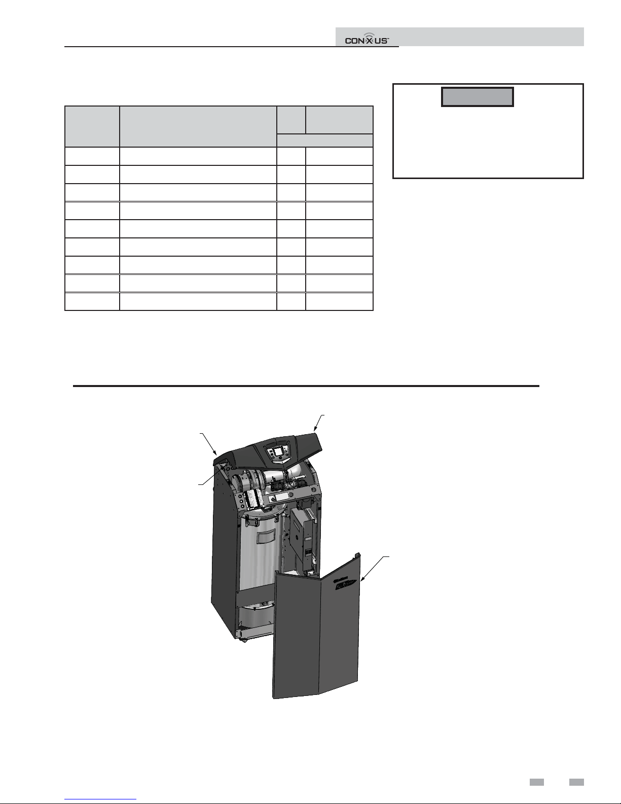
To gain access to the
interior of the unit
1. Turn the main power OFF.
2. Turn the main manual gas shuto to the
appliance OFF.
3. Remove the front door panel (no tools
required).
Figure 2-1_Gain Access to the Interior of the Unit
ON/OFF SWITCH
(ON REAR OF UNIT)
PROP ROD
PROP THE BEZEL UP
NOTE: When required,
remove brace.
REMOVE FRONT PANEL
(no tools required)
IMG01095
NOTE: FTXL shown for
illustration purposes only.
3
Page 4
2 CON·X·US Installation
L
Installation and Operation Instructions
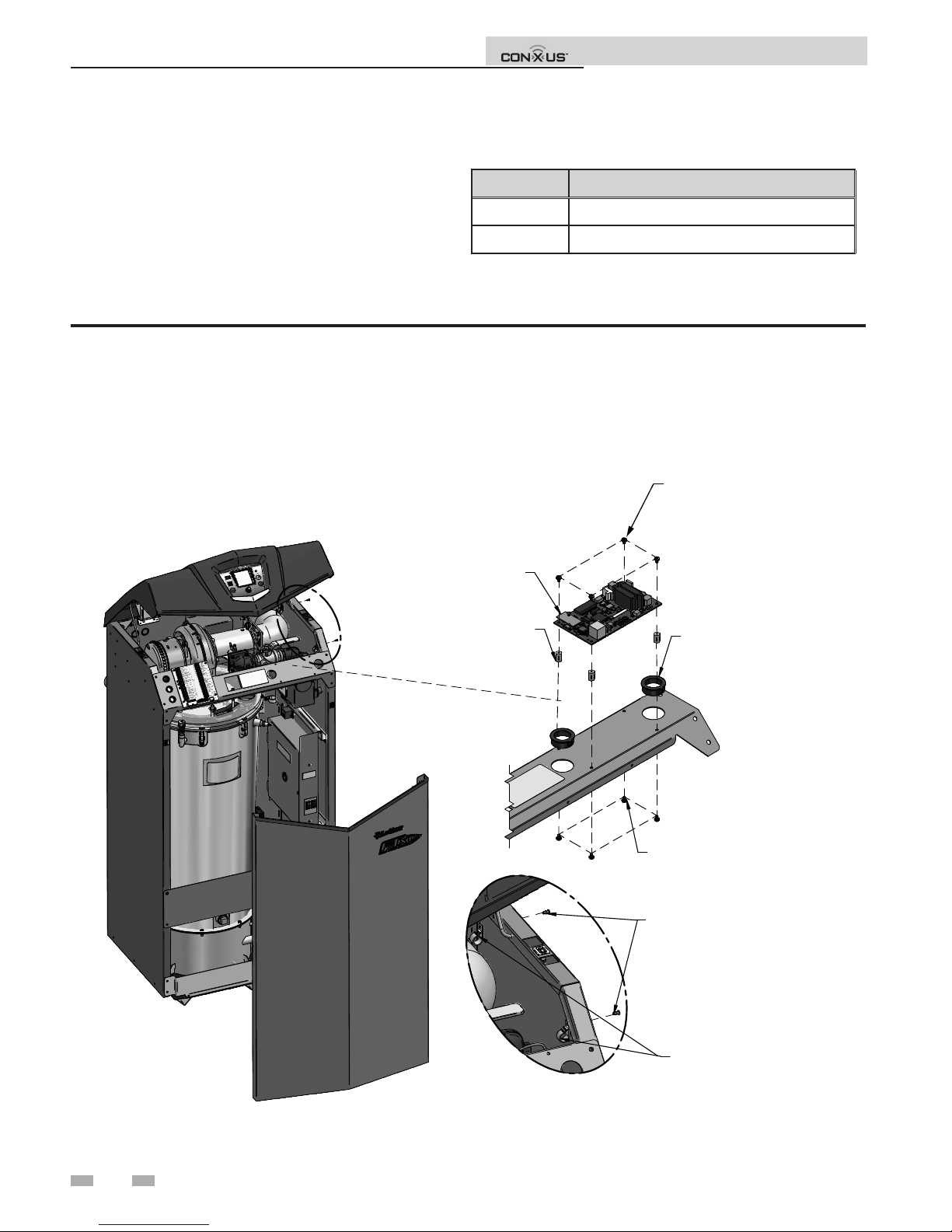
Installation procedure
1. Using four (4) 100053762 screws, install the four (4)
stando s (100134798) into the four (4) small holes on the
front right side of the unit (see FIG.’s 2-2A through
2-2F).
2. Using four (4) 100053762 screws, install the CON·X·US
board (100094892) onto the stando s installed in Step 2.
Figure 2-2A_Install FTXL CON·X·US Board
Table 2B - List of bracket kits
Part # Description
100265396
100265397
KIT,BRKT,BEZEL,CONXUS,KB
KIT,BRKT,BEZEL,CONXUS,WH
NOTE: FTXL Models Only:
a. Install two (2) push rivets (100134843) on the right side of the unit (reference Detail A). Once installed attach the harness
clips (100137491) to the push rivets on the inside of the unit (Detail A), above the main control panel.
b. Install two (2) bushings (100163015) into the le and right side of the CON·X·US board.
4X SCREW, PHP, 6-32 X 1/4 ST
CON·X·US BOARD
A
4X STAND-OFF, #6x1/2" HEX
2X BUSHING, SNAP, 1-1/4"
4X SCREW,PHP,6-32 X1/4,STL
2X RIVET, NYLON PUSH
2X HARNESS CLIPS
4
DETAIL A
IMG01102
Page 5
2 CON·X·US Installation (continued)
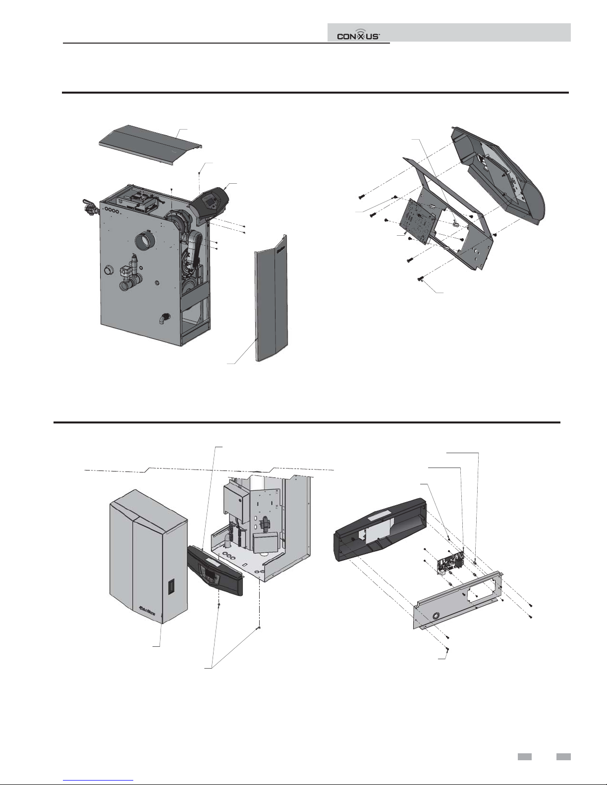
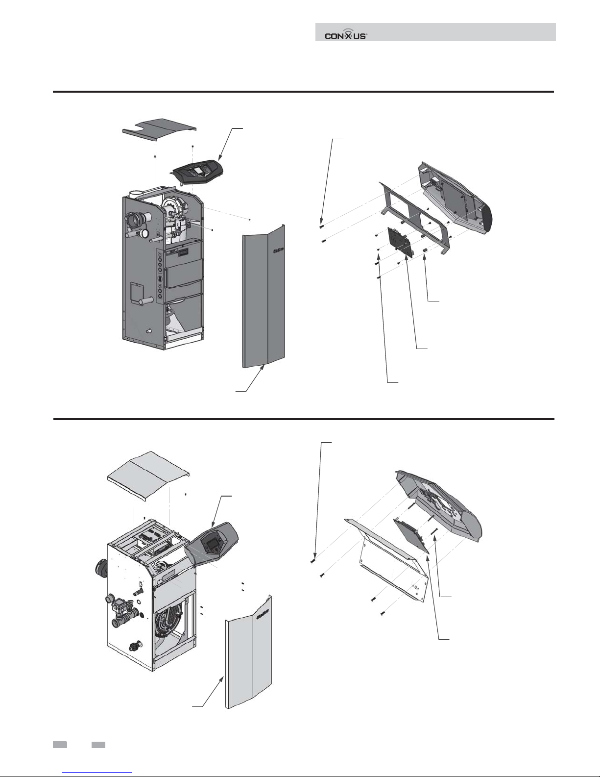
Figure 2-2B_Install KB CON·X·US Board
Installation and Operation Instructions
REMOVE TOP
REMOVE 6X
SCREW,PHP,SHTMTL,,#10 X 1/2
REMOVE BEZEL
REMOVE FRONT
DOOR
INSTALL 4X
STAND-OFF,HEX,6-32 X 1/2,STL,NICKEL
INSTALL 8X
SCREW,PHP,
6-32 X 1/4,STL
INSTALL
RELAY,REMOTE
MONITORING
REMOVE 4X
SCREW,PHP,PLASTIT,#8X1/2,STL,ZINC
IMG01191
NOTE: On units purchased after Serial #1915 the bezel bracket will not be required. If purchased between Serial #H10 to D15 the
bezel bracket (see Table 2B on page 4) is required. Units purchased prior to Serial #H10 are not compatible.
Figure 2-2C_Install WH CON·X·US Board
INSTALL 4X
STAND-OFF,HEX,6-32 X 1/2,STL,NICKEL
REMOVE 4X
SCREW,PHP,PLASTIT,#8X1/2,STL,ZINC
INSTALL
RELAY,
REMOTE MONITORING
INSTALL 8X
SCREW,PHP,6-32 X 1/4,STL
IMG01193
REMOVE FRONT DOOR
REMOVE 2X
SCREW,PHP,SHTMTL,#10X1/2
REMOVE BEZEL
NOTE: On units purchased after Serial #1915 the bezel bracket will not be required. If purchased between Serial #H10 to D15
the bezel bracket (see Table 2B on page 4) is required. Be certain to record the CON·X·US board QR code (see FIG. 3-9 on page
12) before mounting the bezel to the unit.
5
Page 6
2 CON·X·US Installation
Figure 2-2D_Install KH CON·X·US Board
Installation and Operation Instructions
DIR# 2000538292 00
REMOVE FRONT DOOR
REMOVE BEZEL
REMOVE 4X
SCREW,PHP,PLASTIT,#8X1/2,STL,ZINC
DIR# 2000538313 00
INSTALL 4X
STAND-OFF,HEX,
6-32 X 1/2,STL,NICKEL
INSTALL
REMOTE MONITORING
INSTALL 8X
SCREW,PHP,6-32 X 1/4,STL
RELAY,
Figure 2-2E_Install AW CON·X·US Board
DIR# 2000538564 00
REMOVE FRONT DOOR
REMOVE BEZEL
REMOVE 4X
SCREW,PHP,PLASTIT,#8X1/2,STL,ZINC
INSTALL 4X
STAND-OFF,HEX,
6-32 X 1/2,STL,NICKEL
INSTALL
REMOTE MONITORING
RELAY,
6
Page 7

2 CON·X·US Installation (continued)
Figure 2-2F_Install SNR CON·X·US Board
Installation and Operation Instructions
DIR# 2000540180 00
CON·X·US BOARD
INSTALL STAND-OFF, HEX,
6-32 X 1/2, STL, NICKEL &
SCREW,PHP,6-32 X 1/4,STL
3. Connect the 24 volt power harness 100190832 in series with the 24 volt side of the transformer and the other end of the power
harness to the CON·X·US board (see FIG. 2-3).
4. Disconnect the ribbon cable from the rear of the display board and route it to the ribbon cable plug on the CON·X·US board
labeled BIC (remove the ribbon cable from the clip underneath the bezel.
5. Connect the ribbon cable (100189402) to the rear of the display and route on the le side of the CON·X·US board and connect
it to the ribbon cable plug labeled DU (see FIG. 2-3).
6. Reinstall the front panel.
7. Turn the power and gas back ON to the unit and resume operation.
Figure 2-3_Wiring Schematic
CONXUS
POWER HARNESS
TRANSFORMER
SECONDARY
24V 60VA
CONTROL,USER INTERFACE
CONXUS KIT RIBBON CABLE TO USER INTERFACE
MAIN CONTROL RIBBON CABLE TO CONXUS
IMG01192
CONXUS BOARD
MAIN CONTROL BOARD
UNIT HARNESS
7
Page 8

3 CON·X·US Registration
Installation and Operation Instructions
NOTICE
Device Registration
1. Search for the CON·X·US board just like you would search for a Wi-Fi connection on your device. Ensure that your green
LED light is ON and that the WLAN LED is OFF.
NOTICE
2. Connect to the device named CON·X·US as shown in FIG. 3-1.
Figure 3-1_Device Connection
e screens depicted in this manual are to be used for illustration purposes only.
If your CON·X·US board was installed in a boiler prior to this one, you may experience longer wait times
for the CON·X·US link to appear.
Connect to CON·X·US
south
8
Page 9

Installation and Operation Instructions
3 CON·X·US Registration (continued)
3. Once connected to the CON·X·US board, you should be redirected to a Login page. Note: If you are not redirected, open
your internet browser and type 192.168.0.1 in the address bar and click GO. At this point, you are choosing the network you
would like the CON·X·US board to be linked with. If the network is secure you will have to enter in the password for the
network.
Figure 3-2_Choose Network
Choose your
network
south
4. Enter the security password for your network and click CONNECT.
Figure 3-3_Enter Password
Click “Connect”
on the network
of your choice
Enter Wi-Fi
password and
click “Connect”
9
Page 10

Installation and Operation Instructions
3 CON·X·US Registration
5. Your screen should tell you when the WiFi connection is complete. You will also notice a WLAN LED light on the upper le side
of the CON·X·US board once the CON·X·US board is connected to your internet source.
Figure 3-4_Connection Complete
6. Download the Android App on Google Play or the Apple App from the App Store.
NOTICE
7. Once installation is complete, click on the CON·X·US App (logo) on your Tablet/Phone.
Figure 3-5_Click on App
To run the CON·X·US App on your device (Tablet/Phone) you must have a version of iOS 7.0 or above or
Android 4.0 or above.
10
Page 11

Installation and Operation Instructions
3 CON·X·US Registration (continued)
8. If you are a new user you will have to create a new account. If you have an existing account, move on to Step 11.
9. To create a new account, open the CON·X·US App and click CREATE NEW ACCOUNT. You will receive an e-mail asking
you to con rm your new account. NOTE: Be sure to check your Junk or Spam folders as your new account email
may default to one of these folders. You will also be directed to a web page. is web page signi es you have completed the
process. Exit the web page and move on to Step 10.
Figure 3-6_Create Account/Login to Existing Account
10. A er creating your account, login to register a CON·X·US board.
11. Once you are logged in you will be directed to the Device Selection Screen. You can now register the unit by clicking on the
REGISTER NEW DEVICE button.
NOTE: e unit, at some point, must have been connected to the internet before registration can occur.
Figure 3-7_Register New Device Button
Register button
University
Gym
3
University
Library
4
University
Dorm
7
University
Hospital
17
University
Cafeteria
L1234567892
L1234567893
L2234567895
L4234567897
L2234567898
123 Main Street
Nashville, TN 37216
500 Palm Street
Nashville, TN 37212
2345 Burkle Road
Nashville, TN 37201
34 White Street
Nashville, TN 37228
456 Washington Blvd
Nashville, TN 37217
11
Page 12

Installation and Operation Instructions
3 CON·X·US Registration
12. ere are required elds on the Device Registration Screen. Ensure ALL required elds are lled in.
Figure 3-8_Fill in Required Fields
NOTE: You can use the SCAN buttons to ll in the QR code (reference FIG. 1-1 on page 2 for QR Code location) on the CON·X·US
board and the serial number of the unit or you can enter them manually.
Figure 3-9_Scan Buttons
Scan buttons for
QR code and serial
number
12
Page 13

3 CON·X·US Registration (continued)
13. When you are nished lling in the elds, click the REGISTER button.
Figure 3-10_Register Button
Installation and Operation Instructions
Register button
14. Once registration has been completed, you will be re-directed to the Device Selection Screen. You are now able to select the
unit to monitor and change parameters with the App at this time.
Figure 3-11_Select Device
Select the job
you wish to
view
University
Gym
3
University
Library
4
University
Dorm
7
University
Hospital
17
University
Cafeteria
L1234567892
L1234567893
L2234567895
L4234567897
L2234567898
123 Main Street
Nashville, TN 37216
500 Palm Street
Nashville, TN 37212
2345 Burkle Road
Nashville, TN 37201
34 White Street
Nashville, TN 37228
456 Washington Blvd
Nashville, TN 37217
13
Page 14

Site Manager
Contact Info
Service
Notification
Setup Tab
Installation and Operation Instructions
4 Permissions
Whomever registers the CON·X·US will be assigned the role of Site Manager. As you register a CON·X·US your user information
will be automatically populated in the site manager eld. e Site Manager is responsible for assigning access to users for each
site. As the Site Manager your contact information will be displayed in the “Site Manager” eld on the “Service Noti cation”
page of the setup tab (see FIG. 4-1).
Figure 4-1 Site Manager Contact Info
To add a user to a CON·X·US enabled boiler the user will need to create an account (reference the Create Account section on
page 11 of this manual). Once the user that you wish to add has created an account, the Site Manager must enter the e-mail
address into the Service Personnel Contact Info section of the Service Noti cation Menu and click the LINK button. is will
grant access to the CON·X·US enabled boiler and will be populated on the user’s available devices list (reference Select Devices
Screen on page 13 of this manual).
NOTE: e UNLINK button can be used to remove a user. If the Site Manager unlinks themselves, the CON·X·US will need
to be re-registered.
Figure 4-2 Enter Contact Information to Add User Access
Enter contact
information to
add user access
14
Page 15

Access Level
check boxes
Installation and Operation Instructions
4 Permissions (continued)
For each service provider, the Site Manager can grant either “View Only” access or “View & Edit” access by clicking one of the
boxes to the right of the service provider’s name. “View Only” access will allow that user to view all information without the
ability to make any changes. If the Site Manager would like to have a user have “View Only” privileges, but receive alerts, the Site
Manager must provide the user with “View & Edit” privileges to allow the user to set up the alerts. Once the setup is complete,
the Site Manager can then change that user’s access level back to “View Only”. “View & Edit” access will allow that user to view
all information and make programming changes.
Figure 4-3 Access Levels
e Site Manager and any user with View & Edit privileges can select which alerts they receive. One, all, or none of these
noti cation types can be selected. By selecting “Lockout” the Site Manager or user will receive a text or e-mail about a lockout
condition. Selecting “Block” will result in an e-mail or text message any time the boiler enters a blocking condition. Blocking
conditions are not lockouts, but are conditions such as high outlet temperature, high ue temperature, or high Delta T’s, that
result in the boiler limiting itself. Blocking conditions can occur o en depending on the operation conditions, but could also
indicate a problem. Anti-cycling Blockings are not relayed. Selecting “Parameter Change” will result in an e-mail or text message
every time a parameter is changed remotely from CON·X·US or locally through the user interface on the boiler.
When a boiler with CON·X·US goes into a fault condition an alert will be sent out via e-mail or text message. A text message will
be sent if a cell phone number is entered and the cell box is checked (see FIG. 4-4 on page 16). Otherwise, the user will receive
an e-mail.
NOTE: Only the Site Manager is able to see all linked personnel. All other personnel will only see the Site Manager.
15
Page 16

4 Permissions
Enter cell phone
number and select cell
box to receive a text
message with lockout
info
Select
Notification
Type
Press these
buttons to link/
unlink *Site
Managers/Users
Figure 4-4 Enter Cell Phone Info
Installation and Operation Instructions
Figure 4-5 Link/Unlink Buttons
*Site Manager can unlink all if unlinked.
16
Page 17

Press this
button to send
new parameters
to the boiler
Installation and Operation Instructions
4 Permissions (continued)
By accessing the Setup tab, the Site Manager and any user with “View and Edit” privileges will be able to make changes to all
accessible parameters and send the parameters to the boiler. To send parameters to the boiler simply click the SEND UPDATE
button. e REVERT CHANGES button will retrieve the last saved parameters and re-populate all the screens with those
parameters.
Figure 4-6 Send New Parameters to Boiler
Press this button
to retrieve the last
saved parameters
and re-populate
all the screens with
those parameters
17
Page 18

Installation and Operation Instructions
Select Desired
Boiler
Use sort function
for ease of
viewing available
boilers
4 Permissions
How to use the sort function
By clicking on the ACCOUNT button you will be taken to a list of all the boilers registered to the Account Manager or user.
You can access any boiler on the list by selecting the desired boiler. e sort function can be used to sort the list of boilers
by serial number, city, or site name.
If a boiler is gray, this means it is not communicating with the internet. is could mean that the boiler is powered OFF or
that the CON·X·US module is not connected to the internet.
Figure 4-7 Sort Function
18
Page 19

5 Troubleshooting
Figure 5-1_CON·X·US LED Layout
WLAN LED
Installation and Operation Instructions
POLARITY
LED
LED 0 - LED 5
IMG01101
Table 5-1 CON·X·US LED Troubleshooting Table
LED DESCRIPTION ERROR CORRECTIVE ACTION
LED 0 N/A
LED 1
Control to Display
Communication Error
LED 2 CON·X·US Communication
LED 3 N/A
LED 4
Control to Display
Communication
LED 5 Power Confi rmation
-- --
RED • Check ribbon cable connections and display.
BLANK
-- --
BLANK
BLANK
• If blank during known transfer through CON·X·US,
review install and registration.
• No display signal received, check ribbon cable
connections.
• Confi rm power on 24 VAC supply from
transformer.
WLAN
Internet Connectivity
Confi rmation
POLARITY Inverse Polarity Alert
BLANK • If after registration, repeat section of set-up.
RED • Swap 24 VAC power and ground.
19
Page 20

This device complies with Part 15 of the FCC Rules. Operation is subject to the following two conditions:
(1) This device may not cause harmful interference. (2) This device must accept any interference received
including interference that may cause undesired operation.
This Class A digital apparatus complies with Canadian ICES-003.
Cet appareil numérique de la classe A est conforme à la norme NMB-003 du Canada.
Revision Notes: Revision A (ECO #C16153) initial release.
Revision B (Change #500000794) refl ects the addition of the Knight and
the Knight Wall Hung.
Revision C (PCP# 3000005597 / CN# 500006010) refl ects the addition
of the Knight Fire Tube, Armor, and Shield models.
CNX-I-O_MM #100160920_DIR #2000001478_Rev C
12/16
 Loading...