

Page 1
DESIGNER’S GUIDE EFFICIENCY+
®
BOILER
150,000 – 300,000 BTU/HR
Page 2

Dear Specifier/Project Manager,
At Lochinvar, we have long recognized the importance of innovation to any
product or service. Those who enter into business must also accept the challenge
of meeting constantly changing needs.
The designer’s guide you are now holding has been designed to make it more
convenient for you to select the perfect Lochinvar boiler for your projects and
provide correct specifications for your teams.
All information has been organized and presented in a succinct, easy-to-use
manner, so you can use and share information confidently and with minimal
effort.
However, it is important to remember that this guide is not intended to replace our
installation manual. Installers should still refer to our installation manual for
specific installation instructions.
We hope our manual will make your work easier and more productive.
As always, we greatly appreciate your input on additional improvements
for the future.
Thanks once again for specifying the Lochinvar family of quality standard
and custom-built water heaters and boilers.
Sincerely,
Lochinvar Corporation
Lochinvar Corporation • 615-889-8900 / Fax: 615-547-1000
Page 3

Lochinvar DESIGNER’S GUIDE EFFICIENCY+ BOILER 615-889-8900 1
Air Removal . . . . . . . . . . . . . . . . . . . . . .18
Boiler Operating Temperature Control . . . .19
Clearances . . . . . . . . . . . . . . . . . . . . . . . .3
Codes . . . . . . . . . . . . . . . . . . . . . . . . . . .2
Combustion & Ventilation Air . . . . . . . . . . .3
Connection To Terminal Strip . . . . . . . . . .19
Contaminants . . . . . . . . . . . . . . . . . . . . . .5
Electrical Requirements (North America) . . 19
Gas Supply . . . . . . . . . . . . . . . . . . . . . .14
Location of Unit . . . . . . . . . . . . . . . . . . . . .2
Low Water Temperature Systems . . . . . . . .17
Outdoor Installation . . . . . . . . . . . . . . . . .13
Outdoor Use . . . . . . . . . . . . . . . . . . . . . . .3
Primary/Secondary Piping . . . . . . . . . . . .15
Relief Valve Piping . . . . . . . . . . . . . . . . . .16
Remote Temperature Control . . . . . . . . . . .19
Special Design Applications . . . . . . . . . . .18
Three-Way Valves . . . . . . . . . . . . . . . . . .16
Venting . . . . . . . . . . . . . . . . . . . . . . . . . . .5
Venting Options . . . . . . . . . . . . . . . . . . . .7
Water Flow Requirements . . . . . . . . . . . .15
Water Velocity Control . . . . . . . . . . . . . . .15
Figures & Tables Index
FIG. 1 Boiler Equipment & Control
Orientation . . . . . . . . . . . . . . . .3
FIG. 2-5 Combustion & Ventilation Air . . .4
FIG. 6 Barometric Damper
Installation . . . . . . . . . . . . . . . . .8
FIG. 7 Multiple Unit Barometric
Damper Installation . . . . . . . . . .8
FIG. 8 E+ Vent With
Sidewall Air Inlet . . . . . . . . . . . .9
FIG. 9 E+ Vent With
Vertical Air Inlet . . . . . . . . . . . .10
FIG. 10 Horizontal Direct Vent . . . . . . .11
FIG. 11 Horizontal Direct Vent Cap . . . .11
FIG. 12 Multiple Sidewall Vent Caps . . .12
FIG. 13 Vertical Direct Vent . . . . . . . . . .12
FIG. 14 Outdoor Venting . . . . . . . . . . .13
FIG. 15 Primary/Secondary
System Piping . . . . . . . . . . . . .16
FIG. 16 Low Temperature Bypass
System Piping . . . . . . . . . . . . .17
FIG. 17 Heating/Chilled
Water System . . . . . . . . . . . . .18
TABLE A. Clearances From
Combustible Construction . . . . . .3
TABLE B. Conventional Venting,
Vent Flue Size . . . . . . . . . . . . . .7
TABLE C. E+ Vent Sidewall
Air Kit Part Numbers . . . . . . . . .9
TABLE D. E+ Vent Horizontal
Air Kit Part Numbers . . . . . . . .11
TABLE E. Vertical Direct Vent Flue &
Air Inlet Sizes . . . . . . . . . . . . .13
TABLE F. Outdoor Vent Kit . . . . . . . . . . .13
TABLE G. Gas Supply Pipe Sizing . . . . . .14
TABLE H. Inlet Gas Pressure . . . . . . . . . .14
TABLE I. Minimum & Maximum
Boiler Flow Rates . . . . . . . . . . .15
TABLE J. Water Flow Requirements . . . . .15
TABLE K. Heat Exchanger Head-loss . . . .16
TABLE L. Amp Draw . . . . . . . . . . . . . . .19
Appendix A: Boiler Piping Diagrams
Primary/Secondary Boiler . . . . . . . . . . . .A1
Multiple Unit - Primary/Secondary . . . . . .A2
Low Temperature Bypass Piping . . . . . . . .A3
Table of Contents
Page 4
CODES
The equipment shall be installed in
accordance with those installation
regulations in effect in the local area where
the installation is to be made. These must be
carefully followed in all cases. Authorities
having jurisdiction must be consulted before
installations are made. In the absence of such
requirements, the installation must conform to
the latest edition of the National Fuel Gas
Code, ANSI Z223.1. Where required by the
authority having jurisdiction, the installation
must conform to American Society of
Mechanical Engineers Safety Code for
Controls and Safety Devices for Automatically
Fired Boilers, No.(CSD-1). All boilers conform
to the latest edition of the ASME Boiler and
Pressure Vessel Code, Section IV. Where
required by the authority having jurisdiction,
the installation must comply with the
Canadian Gas Association Code,
CAN/CGA-B149.1 and/or B149.2
and/or local codes.
LOCATION OF UNIT
Locate the unit so that if water connections
should leak, water damage will not occur.
When such locations cannot be avoided,
it is recommended that a suitable drain
pan, adequately drained, be installed
under the unit. The pan must not restrict
combustion air flow.
Under no circumstances is the
manufacturer to be held responsible for
water damage in connection with this
unit or any of its components.
2 Lochinvar
DESIGNER’S GUIDE EFFICIENCY+ BOILER 615-889-8900
L ochinv ar
Water Velocity
(
See Page 15 for minimum and
maximum flow rates.)
Piping Requirements and
Specialties
(
See Page 15 for piping
application requirements.)
System Water Temperature
(
See Page 17 for piping and
design recommendations.)
System and Boiler Control
(See Page 19 for boiler
operating and temperature
control.)
Air Elimination and
Expansion Tank Placement
(
See Page 18 for air removal
information.)
In designing
a hot water heating system,
pay special attention to:
1.
Page 5
The indoor unit must be installed so that
the ignition system components are
protected from water (dripping, spraying,
rain, etc.) during appliance operation and
service (circulator replacement, control
replacement, etc.)
Units located in a residential garage
must be installed so that all burners and
burner ignition devices have a minimum
clearance of 18” (46cm) above the floor.
The unit must be located or protected so
that it is not subject to physical damage
by a moving vehicle.
The appliance must be installed on a
level floor. A combustible wood floor may
be used without additional bases or
special floor buildup. Maintain required
clearances from combustible surfaces.
The appliance must not be installed on
carpet or other combustible material other
than wood flooring.
SPECIAL LOCATION:
OUTDOOR USE
Efficiency+ Models are approved for
outdoor installations. Outdoor models
have additional location and clearance
requirements. These requirements must be
adhered to carefully, since wind, rain, snow
and cold cannot be controlled in outdoor
applications. See Outdoor Installation,
in the venting section on page 13.
COMBUSTION AND VENTILATION
Provisions for combustion and ventilation
air must be in accordance with Section
5.3, Air for Combustion and Ventilation, of
the latest edition of the National Fuel Gas
Code, ANSI Z223.1, or in Canada, the
latest edition of CGA Standard B149
2.
3.
4.
Lochinvar DESIGNER’S GUIDE EFFICIENCY+ BOILER 615-889-8900 3
5.
(TABLE A)
CLEARANCES FROM COMBUSTIBLE CONSTRUCTION
RIGHT SIDE 1”
REAR 1”
LEFT SIDE 6” (24” suggested for service)
FRONT 3” (24” suggested for service)
Suitable for closet installation
TOP 3”
*Allow sufficient space for servicing pipe connections, pump
and other auxiliary equipment, as well as the appliance.
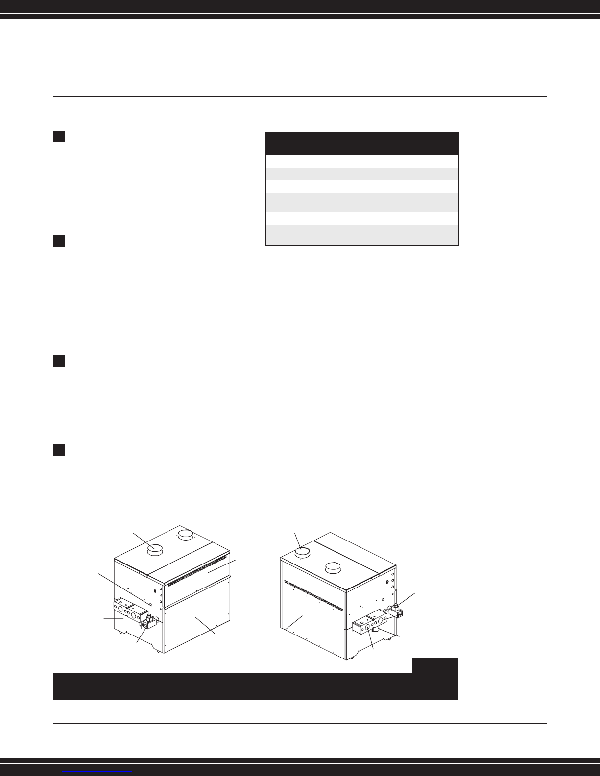
FLUE PRODUCTS
VENT
GAS
CONNECTION
SYSTEM
RETURN
BURNER
INSPECTION
PORT
SYSTEM
SUPPLY
BACK
AIR INLET
TERMINAL
STRIP
(INSIDE)
120V
ELECTRICAL
CONNECTION
DRAIN
LEFT SIDE
FRONT
EB150-300
(FIG. 1) BOILER EQUIPMENT &
CONTROL ORIENTATION
Page 6
4 Lochinvar DESIGNER’S GUIDE EFFICIENCY+ BOILER 615-889-8900
Installation Code for Gas Burning Appliances
and Equipment, or applicable provisions of
the local building codes.
The equipment room must be provided with
properly sized openings to assure adequate
combustion air and proper ventilation, when
the unit is installed with conventional venting
or sidewall venting.
If air is taken directly from outside
the building with no duct, provide
two permanent openings:
A. Combustion air opening with a
minimum free area of one square inch per
4000 Btu/hr input. This opening must be
located within 12” (30 cm) of the bottom of
the enclosure.
B. Ventilation air opening with a minimum
free area of one square inch per 4000
Btu/hr input. This opening must be
located within 12” (30 cm) of the top of
the enclosure.
If combustion and ventilation air is
taken from the outdoors using a
duct to deliver the air to the
mechanical room, each of the two
openings should be sized based on a
minimum free area of one square inch per
2000 Btu/hr.
If air is taken from another interior
space, each of the two openings
specified above should have a net free
area of one square inch for each 1000
Btu/hr of input, but not less than 100
square inches (645 cm
2
).
If a single combustion air opening is
provided to bring combustion air in
directly from the outdoors, the opening
must be sized based on a minimum free
area of one square inch per 3000 Btu/hr.
This opening must be located within 12”
(30 cm) of the top of the enclosure.
L ochinv ar
(FIG. 4) COMBUSTION AIR FROM INTERIOR SPACE
(FIG. 3) COMBUSTION AIR THROUGH DUCTWORK
2.
3.
4.
(FIG. 5) COMBUSTION AIR FROM
OUTSIDE SINGLE OPENING
(FIG. 2) COMBUSTION AIR DIRECT FROM OUTSIDE
1.
EXAMPLE OF
SIZING FOR
COMBUSTION
& VENTILATION
AIR OPENINGS
(BOILER WITH
300,000 BTU/HR
INPUT):
When combustion and
ventilated air is taken from
directly outside the building
(FIG. 2), divide the total BTU’s
by 4,000. This yields 75 sq.in.
of “Free Area” without
restriction.
300,000 ÷ 4,000 =
75 sq.in.
Since the air opening is 50%
closed due to screens and
louvers, the total opening
MUST be multiplied by 2.
75 sq.in. x 2 =
150 sq.in.
This project requires one
Ventilation Air Opening with
net “Area” of 75 square
inches with louver dimensions of
12” x 15”= 168 sq.in.
and one Combustion Air
Opening with net “Area”
of 75 square inches with
louver dimensions of
12” x 15”= 168 sq in.
CAUTION: Under no circumstances should
the equipment room be under a negative
pressure when atmospheric combustion
equipment is installed in the room.
Page 7

Lochinvar DESIGNER’S GUIDE EFFICIENCY+ BOILER 615-889-8900 5
CONTAMINANTS
Combustion air drawn from an interior or
exterior space must be free of any chemical
fumes which could be corrosive to the boiler.
Burning chemical fumes results in the
formation of corrosive acids which attack
the boiler and cause improper combustion
and premature failure of the boiler and vent.
These fumes are often present in areas where
refrigerants, salts, and solvents are used.
Therefore, be aware of swimming pool
equipment, water softening, and cooling
system placement.
VENTING
General
Vent installations for connection to gas vents
or chimneys must be in accordance with
Part 7, “Venting of Equipment”, of the latest
edition of the National Fuel Gas Code, ANSI
Z223.1, or applicable provisions of the local
building codes.
The connection from the appliance vent to the
stack must be as direct as possible and
sized correctly, using the proper vent table.
The horizontal breeching of a vent must
have at least 1/4” rise per linear foot.
The horizontal portions should also be
supported for the design and weight of the
material employed to maintain clearances,
prevent physical damage and separation of
joints.
The connection from the appliance vent to the
stack or vent termination outside the building
must be made with listed Type “B” double
wall vent (or equivalent) for conventional vent
applications.
When utilizing direct vent capabilities
connections must be made with AL29-4C
stainless steel (or equivalent) vent material.
Material should be sized according
to vent sizing tables (FAN column) in
the latest edition of the National Fuel
Gas Code.
The vent materials and accessories, such as
firestop spacers, thimbles, caps, etc., must
be installed in accordance with the
manufacturer’s listing.
The vent connector and firestop shall provide
correct spacing to combustible surfaces and
seal to the vent connector on the upper and
lower sides of each floor or ceiling through
which the vent connector passes.
Any improper operation of the common
venting system in the existing building must
be corrected when new equipment is
installed, so the installation conforms to the
latest edition of the National Fuel Gas Code,
ANSI Z223.1.
CAUTION!
EXHAUST FANS:
Any fan or equipment
which exhausts air from
the equipment room may
deplete the combustion
air supply and/or cause
a down draft in the
venting system. If a fan
is used to supply
combustion air to
the equipment room, it
must be sized to make
sure that it does not
cause drafts which could
lead to nuisance
operational problems
with the boiler.
Page 8
6 Lochinvar DESIGNER’S GUIDE EFFICIENCY+ BOILER 615-889-8900
The efficiency of this appliance allows its
products of combustion to be vented through
a smaller vent pipe when compared to units
of the same Btu/hr capacity. For this reason,
resizing common venting systems is
recommended for proper operation.
When resizing any portion of the common
venting system, it should be resized to
approach the minimum size as determined
using the appropriate tables (FAN column) in
the National Fuel Gas Code.
Failure to resize a common venting system
could lead to the formation of condensate
and premature deterioration of the vent
material.
Flue gas condensate can freeze on exterior
walls or on the vent cap. Frozen condensate
on the vent cap can result in a blocked flue
condition. Some discoloration to exterior
building surfaces can be expected. Adjacent
brick or masonry surfaces should be
protected with a rust resistant sheet metal
plate.
Vent connectors serving appliances vented by
natural draft must not be connected to
any portion of a mechanical draft system
operating under positive pressure.
Connection to a positive pressure stack may
cause flue products to be discharged into the
living space causing serious health injury.
Locate units as close as possible to a chimney
or gas vent.
Vent Terminations
When locating the vent cap, consider the effects
of snow, leaf dropping, etc., to ensure that no
blockage occurs.
The distance of the vent terminal from adjacent
public walkways, adjacent buildings, windows
that open and building openings must comply
with the latest edition of the National Fuel Gas
Code, ANSI Z223.1.
The vent terminal must be vertical and
exhaust outside the building at least 2 feet
(0.6m) above the highest point of the roof
within a 10 foot (3.0m) radius of the
termination.
The vertical termination must be a minimum
of 3 feet (0.9m) above the point of exit in the
rooftop.
A vertical termination less than 10 feet (3.0m)
from a parapet wall shall be a minimum of 2
feet (0.6m) higher than the parapet wall.
The vent cap shall terminate at least 3 feet
(0.9m) above any forced air inlet within 10
feet (3.05m). The vent shall terminate at least
4 feet (1.2m) below, 4 feet (1.2m)
horizontally from or 1 foot (0.30m) above
any door, window, or gravity air inlet to the
building.
Do not terminate the vent in a
window well, stairwell, alcove,
courtyard, or other recessed area.
The vent cannot terminate below
grade.
L ochinv ar
IMPORTANT!
The vent cap should
have a minimum
clearance of 4 feet
horizontally from electric
meters, gas meters,
regulators, air inlets and
air relief equipment.
Additionally, the vent
cap should never be
located above or below
these items, unless a 4
foot horizontal distance
is maintained.
NOTE:
The weight of the
venting system MUST
NOT rest on the boiler.
It should be properly
supported.
WARNING
Vent connectors serving
gas appliances, which
operate under a
negative vent pressure,
shall not be connected
into any portion of
mechanical draft
systems operating under
positive vent pressure.
Page 9

Masonry Chimney
A masonry chimney must be properly sized
for the installation of a high efficiency gas fired
appliance. Venting of a high efficiency
appliance into a cold or oversized masonry
chimney can result in operational and safety
problems.
Exterior masonry chimneys, with one or more
sides exposed to cold outdoor temperatures, are
more likely to have venting problems. For this
reason, exterior masonry chimneys are not
generally recommended to vent high efficiency
gas appliances.
An interior masonry chimney, which is not
exposed to the outdoors below the roofline, may
be used to vent high efficiency gas appliances
based on the results of careful inspection,
proper sizing and local code approval. If there
is any doubt about the sizing or condition of a
masonry chimney, it should be relined with a
properly sized and approved chimney liner
system.
An interior masonry chimney should be carefully
inspected to determine its suitability for the
venting of flue products.
A clay tile lined chimney must be structurally
sound, straight and free of misaligned tile, gaps
between liner sections, missing sections of liner
or any signs of condensate drainage at the
breeching or clean out.
If there is any doubt about the condition of a
masonry chimney, it should be relined.
Metallic liner systems (Type “B” double-wall,
flexible, or rigid metallic liners) are
recommended to line or reline an existing
masonry chimney. Consult with local code
officials to determine code requirements or the
advisability of using a lined masonry chimney
or relining of a masonry chimney.
VENTING OPTIONS
Conventional Venting - Negative Draft
Size vent material according to the “FAN”
column of vent sizing tables in the latest edition
of the National Fuel Gas Code. “FAN” applies
to Category I fan assisted combustion
appliances with natural draft. Utilize Category
I type “B” vent material for all conventional
venting applications.
A bell increaser is provided and installed
directly on the boiler vent outlet. The bell
increases the boiler vent size by 1 inch
(25.4mm) in diameter. The vent connection
is made directly to the bell increaser on the
top of the unit. No additional draft diverter
or barometric damper is required.
(TABLE B)
CONVENTIONAL VENTING, VENT CONNECTION SIZE
CONVENTIONAL
MODEL VENT FLUE SIZE
EB150 5
”
EB200 5
”
EB250 6”
EB300 6”
Lochinvar DESIGNER’S GUIDE EFFICIENCY+ BOILER 615-889-8900 7
Page 10

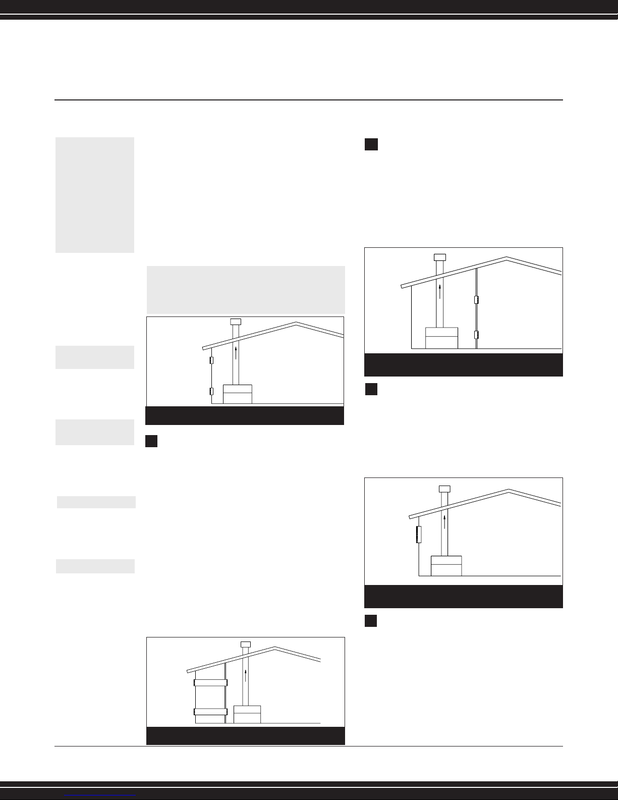
8 Lochinvar DESIGNER’S GUIDE EFFICIENCY+ BOILER 615-889-8900
When each unit is installed with an individual
vent, and the negative draft is higher than the
specified range (0.02 to 0.05 inches of water
column), a barometric damper will be necessary.
Multiple unit installations with combined
venting require barometric dampers to
regulate draft at each unit. The negative
draft must be within the range of 0.02 to
0.05 inches of water column to ensure
proper operation.
All draft readings are made while the unit is
in stable operation (approximately 2 to 5
minutes).
For this type of installation, it is best to use a
draft control for each boiler located on the
riser between the vent outlet and the
breeching - Location “A”. (Figure 7)
When this riser is too short to permit the
installation of a control, locate a separate
control for each boiler on the main breeching
as illustrated in Location “B”. (Figure 7)
If, because of general crowding or other
reasons, neither of these locations are
possible, use a single large control in the
breeching between the boiler nearest the
chimney and the chimney, as shown in
Location “C”. (Figure 7)
Conventional Venting with Direct
Combustion Air Intake (E+Vent)
This vent system uses two pipes, one vertical
pipe with a roof top termination for the flue
products and one pipe for combustion air. The
combustion air pipe may terminate
horizontally with a sidewall air inlet or
vertically with a roof top air inlet. All
instructions for “Conventional Venting Negative Draft” apply to “Conventional
Venting with Direct Combustion Air”. The flue
may be combined with the vent from any
other negative draft, Category I appliances.
Utilize Category I type “B” vent material for
venting flue products.
L ochinv ar
WATER HEATER/BOILER
BAROMETRIC DAMPER ON SINGLE UNIT INSTALLATION
Lined
Chimney
WATER HEATER/BOILER
BAROMETRIC DAMPER ON SINGLE UNIT INSTALLATION
(FIG. 6) BAROMETRIC DAMPER INSTALLATION
(FIG. 7) MULTIPLE UNIT BAROMETRIC
DAMPER INSTALLATION
NOTE:
An unlined masonry
chimney should not be
used to vent flue
products from this high
efficiency appliance.
Page 11

The sidewall or vertical roof top E+Vent
combustion air supply system has specific vent
material and installation requirements.
The air inlet pipe connects directly to the boiler
to supply combustion air. In most installations,
the combustion air inlet pipe will be a
dedicated system with one air inlet pipe per
boiler. Multiple air inlets may be combined if
the guidelines in “Combined Air Inlet Points”
are followed. The air inlet pipe will be
connected to a combustion air inlet cap as
specified in this section. Combustion air
supplied from outdoors should be free of
contaminants. The air inlet pipe(s) must be
sealed. Select air inlet pipe material from the
following specified materials:
• PVC, CPVC or ABS (4”, 5” or 6” I.D.).
• Dryer vent (not recommended for roof
top air inlet)
• Galvanized steel vent pipe with joints
and seams sealed.
• Type “B” double wall vent with joints
and seams sealed.
The total equivalent length of the sidewall or
vertical roof top E+Vent combustion air inlet pipe
shall not exceed a maximum of 50 equivalent
feet (15.2m) in length. Subtract 5 feet (1.5m) for
each elbow in the air intake system.
Sidewall Air Inlet
The sidewall air inlet cap is supplied in the E+
Sidewall Vent Kit. Each kit includes a sidewall
combustion air inlet cap to supply air to a single
boiler and instructions for proper installation. The
part number for each kit is listed by unit size.
Locate units as close as possible to the sidewall
where the combustion air supply system will be
installed.
To prevent recirculation of flue products from an
adjacent vent cap into the combustion air inlet,
follow all applicable clearance requirements in
the latest edition of the National Fuel Gas Code
and instructions in this guide.
The combustion air inlet cap must be placed at
least one foot (0.3m) above ground level and
above normal snow levels.
NOTE:
The use of double wall
vent material for the
combustion air inlet pipe
is recommended in cold
climates to prevent the
accumulation of
condensation on the
pipe exterior.
(FIG. 8) E+ VENT WITH SIDEWALL AIR INLET
(TABLE C)
E+ VENT SIDEWALL AIR KIT PART NUMBERS
MODE CONVENTIONAL VENT AIR SIDEWALL
NUMBER FLUE SIZE* INLET PIPE** E+ VENT KIT
EB150 5
”
4
”
SVK 3020
EB200 5
”
4
”
SVK 3020
EB250 6
”
5
”
SVK 3021
EB300 6
”
5
”
SVK 3021
*Vent size with 1” increaser installed for conventional negative
draft venting.
Lochinvar
DESIGNER’S GUIDE EFFICIENCY+ BOILER 615-889-8900 9
(FIG. 9) E+ VENT WITH VERTICAL AIR INLET
Page 12

10 Lochinvar DESIGNER’S GUIDE EFFICIENCY+ BOILER 615-889-8900
Vertical Air Inlet
The air inlet cap for the vertical roof top
air inlet is assembled from components
purchased locally. The air inlet cap consist
of two 90° ells installed at the point of
termination for the air inlet pipe.
The point of termination for the combustion
air inlet cap must be at least 2 feet (0.6m)
below the point of flue gas termination
(vent cap) if it is located within 10 ft. (3.0m)
of the flue outlet.
The termination ell on the air inlet must be
located a minimum of 12” (0.3m) above the
roof or above normal levels of snow
accumulation. It must not be placed closer
than 10 feet (3.0m) from an inside corner of
an L-shaped structure.
Incorrect location of the air inlet cap can
allow the discharge of flue products to be
drawn into the combustion process of the
boiler. This can result in incomplete
combustion and potentially hazardous levels
of carbon monoxide in the flue products.
Combined Air Inlet Points
The air inlet pipes from multiple boilers can
be combined into a single common
connection, if the common air inlet pipe has a
cross sectional area equal to or larger than
the total area of all air inlet pipes connected
to the common air inlet pipe.
The air inlet point for multiple boiler air inlets
shall be provided with an exterior opening
which has a free area equal to or greater
than the total area of all air inlet pipes
connected to the common air inlet. This
exterior opening for combustion air must
connect directly to the outdoors.
The total length of the combined air inlet pipe
must not exceed a maximum of 50
equivalent feet(15.2m). Deduct the restriction
in area provided by any screens, grills or
louvers installed in the common air inlet point.
Screens, grills, or louvers installed in the
common air inlet can reduce the free area
of the opening from 25% to 75% based on
the materials used. The air inlet cap for the
combined air supply from multiple boilers can
be purchased or fabricated in the field.
Direct Venting
A direct vent boiler uses a two pipe system,
one pipe for the flue products and one pipe
for the combustion air supply.
The flue cannot be combined with any other
appliance vent or common vent from multiple
boilers. The vent on a direct vent system will
have a positive pressure in the flue, which
requires all vent joints and seams to be
sealed gas-tight. The flue from a direct vent
system shall have a condensate drain with
provisions to properly collect and dispose of
any condensate that may occur in the venting
system. Direct vent systems require Category
IV vent material with AL29-4C approved
stainless steel.
The air inlet pipe connects directly to the
boiler to supply combustion air. The air inlet
pipe must be sealed. Choose acceptable
L ochinv ar
EXAMPLE OF
COMBINED
AIR INLET
SIZING
Two 5” air inlet pipes
(19.6 in2area each) have
a total area of 39.2 in
2
requiring an 8” (50.3 in
2
area) common air inlet
pipe.
Page 13

combustion air pipe materials from those
specified in this section. Approved material
for air inlet pipes include: PVC, CPVC or ABS
(3”, 4”, 5” or 6” I.D.), dryer vent, and
galvanized steel vent pipe with joints and
seams sealed.
The total equivalent length of the direct vent
flue pipe or the air inlet pipe should not
exceed a maximum of 50 equivalent feet
(15.2m) in length for each pipe. Subtract
5 feet (1.5m) for each elbow in the vent
pipe or air intake system.
Horizontal Direct Vent
Horizontal direct vent applications require a
vent kit which will be supplied by Lochinvar
to assure proper operation.
The part number for each kit is listed by unit
size. Each kit includes a sidewall vent cap for
flue products, a firestop, a combustion air
inlet cap, and instructions for proper
installation.
It is important to be careful in the placement
of the horizontal direct vent caps. Combustion
air supplied from outdoors should be free of
contaminants.
To prevent recirculation of flue products into
the combustion air inlet:
The combustion air inlet cap must not be
installed above the flue outlet cap.
Maintain a minimum 3 foot (0.9m) radius
clearance between the combustion air inlet
cap and the flue outlet cap. Additional
space may be required between caps
where high winds may occur.
The combustion air inlet cap and vent cap
for flue outlet must be located on the
same sidewall and in the same pressure
zone.
Do not place the combustion air inlet cap
closer than 10 feet (3.0m) from an inside
corner of an L-shaped structure.
Place the combustion air inlet cap at least
one foot (0.3m) above ground level and
above normal snow levels.
(FIG. 10) HORIZONTAL DIRECT VENT
(FIG. 11) HORIZONTAL DIRECT VENT CAP
(TABLE D)
HORIZONTAL DIRECT VENT KIT PART NUMBERS
MODEL FLUE AIR PART
NUMBER PIPE SIZE INLET PIPE NUMBER
EB150 4” 4” HDK 3013
EB200 4” 4” HDK 3013
EB250 5” 5” HDK 3014
EB300 5” 5” HDK 3014
1.
NOTE:
The use of double wall
vent material for the
combustion air inlet
pipe is recommended in
cold climates to prevent
the accumulation of
condensation on the
pipe exterior.
2.
Lochinvar
DESIGNER’S GUIDE EFFICIENCY+ BOILER 615-889-8900 11
3.
4.
5.
Page 14

Multiple Unit Applications
(Horizontal Direct Vent)
The combustion air inlet caps for multiple unit
installations must maintain the minimum 3
foot (0.9m) radius clearance below or
horizontally from the closest flue outlet.
Multiple flue outlet caps may be installed side
by side, and multiple air inlet caps may be
installed side by side, but the 3 foot (0.9m)
radius minimum clearance between air inlet
and flue outlet must be maintained.
All clearance and installation requirements in
this section and the applicable portions of the
general venting section must be maintained
on multiple unit installations.
Vertical Direct Vent
Vertical direct vent applications do not require
a vent kit to be supplied by Lochinvar. The
vent cap and air inlet cap for vertical direct
vent applications are fabricated or purchased
in the field.
A vertical vent cap, as specified by the vent
material manufacturer, is used to vent the flue
products to the outdoors. The air inlet cap
consists of two 90° ells installed at the point
of termination for the air inlet pipe. The
termination ell on the air inlet must be
located a minimum of 12” (15.2cm) above
the roof or above normal levels of snow
accumulation. The point of termination for the
air inlet shall be 24” (0.6m) lower than the
point of flue gas termination, if it is located
within 10 ft. (3.0m) of the flue outlet.
Incorrect installation and/or location of the
air inlet cap can allow the discharge of flue
products to be drawn into the combustion
process on the boiler. This can result in
incomplete combustion and potentially
hazardous levels of carbon monoxide in the
flue products.
L ochinv ar
12 Lochinvar DESIGNER’S GUIDE EFFICIENCY+ BOILER 615-889-8900
(FIG. 13) VERTICAL DIRECT VENT
CAUTION!
Boilers which are shut
down or will not
operate may
experience freezing
due to convective air
flow in the air inlet
pipe connected to the
unit. Proper freeze
protection MUST be
provided.
(FIG. 12) MULTIPLE SIDEWALL VENT CAPS
AIR INLETS
AIR INLETS
3 feet
MIN.
3 feet
MIN.
FLUE OUTLETS
CAUTION!
Maintain a minimum
3 foot (0.9m) radius
clearance between
the combustion air
inlet cap and the
flue outlet cap.
(TABLE E) – VERTICAL DIRECT VENT,
FLUE AND AIR INLET SIZES.
MODEL DIRECT VENT AIR INLET
NUMBER FLUE SIZE PIPE
EB150 4” 4”
EB200 4” 4”
EB250 5” 5”
EB300 5” 5”
Page 15

Multiple Unit Applications
(Vertical Direct Vent)
The combustion air inlet caps for multiple unit
installations must maintain the minimum 2
foot (0.6m) clearance below the closest
vertical flue outlet if within 10 feet (3.0m).
Multiple flue outlet caps may be installed side by
side and multiple air inlet caps may be installed
side by side, but the air inlet must always be at
least 2 feet (0.6m) below the closest flue outlet if
the outlet is within 10 feet (3.0m).
OUTDOOR INSTALLATION
Units are self venting and can be used
outdoors when installed with the optional
Outdoor Vent Kit. This kit includes a one piece
top cover which replaces the standard two
piece cover, air inlet cap, exhaust cap, gas
valve cover and junction box cover. The cap
mounts directly to the top of the water heater
and covers the flue outlet and combustion air
inlet openings on the jacket. No additional
vent piping is required. Maintain a minimum
clearance of 3" (76mm) to combustible
surfaces and a minimum of 3" (76 mm)
clearance to the air inlet.
An outdoor unit should not be located so that
high winds can deflect off of adjacent walls,
buildings or shrubbery causing recirculation.
Recirculation of flue products may cause
operational problems, bad combustion or
damage to controls. The unit should be located
at least 3 feet (0.91m) from any wall or vertical
surface to prevent adverse wind conditions from
affecting performance. Multiple unit outdoor
installations require 48" (1.22 m) clearance
between each vent cap. The outdoor cap must
be located 4 feet (1.22 m) below and 4 feet
(1.22 m) horizontally from any window, door,
walkway or gravity air intake.
The combustion air inlet of the outdoor cap must
be located at least one foot (0.30 m) above
grade and above normal snow levels. The water
heater must be at least 10 feet (3.05 m) away
from any forced air inlet and at least 3 feet (0.91
m) outside any overhang. Do not install in
locations where rain from building runoff drains
will spill onto the water heater. Lochinvar must
furnish an outdoor vent kit in accordance with
CSA international requirements. Each kit includes
the flue outlet/combustion air inlet, gas valve
cover, junction box cover and one piece unit top.
Freeze Protection- Outdoor Installation
A snow screen should be installed to prevent
snow and ice accumulation around the
appliance or its venting system.
If for any reason the unit is to be shut off:
(a.) Shut off water supply.
(b.) Drain unit completely.
(c.) Drain pump and piping.
If freeze protection is not provided for the
system, a low ambient temperature alarm or
automatic drain system is recommended.
Lochinvar DESIGNER’S GUIDE EFFICIENCY+ BOILER 615-889-8900 13
(FIG. 14) OUTDOOR VENTING
(TABLE F) –OUTDOOR VENT KITS
MODEL OUTDOOR
NUMBER VENT KIT
EB150 ODK3069
EB200 ODK3070
EB250 ODK3071
EB300 ODK3072
Page 16

14 Lochinvar DESIGNER’S GUIDE EFFICIENCY+ BOILER 615-889-8900
GAS SUPPLY
Safe operation of unit requires properly
sized gas supply piping (See TABLE G).
Gas pipe size may be larger than the
heater connection.
An internal gas pressure regulator is required
if upstream pressure exceeds 6 oz. (10.5"
water column), an intermediate gas
pressure regulator, of the lockup type,
must be installed.
Installation of a union is suggested for
ease of service.
Install a manual main gas shutoff valve
with test plug, outside of the appliance
gas connection and before the gas valve,
when local codes require.
A trap (drip leg) should be provided in the
inlet of the gas connection to the unit.
High Altitude Applications
Atmospheric pressure decreases as the height
above sea level increases. At any altitude
above sea level, a cubic foot will contain less
gas than a cubic foot at sea level. Thus, the
heating value of a cubic foot of fuel gas will
decrease as height above sea level increases.
Specific gravity of a gas with respect to sea
level also decreases with altitude.
These changes in heating value and specific
gravity tend to offset each other. However, as
elevation above sea level is increased, there
is less oxygen per cubic foot of air. Therefore,
heat input rate should be reduced in an
appliance above 2000 feet. Ratings should
be reduced at the rate of 4 percent for each
1000 feet above sea level.
WATER CONNECTIONS
Inlet and Outlet Water Connections
For ease of service, install unions on inlet and
outlet of the boiler. The connection on the unit
marked “Inlet” should be used for return
water from the system. The connection on the
header marked “Outlet” should be connected
to the system supply. (See Boiler Piping
diagrams, Appendix A).
L ochinv ar
NOTE:
Care should be
taken to measure
temperature rise
and maintain proper
water velocity in
the heat exchanger.
(TABLE H) – INLET GAS PRESSURE REQUIREMENTS
NATURAL GAS LPG
Max. Allowable 10.5” 13”
(Inches-water column)
Min. Allowable 4.7” 8”
(Inches-water column)
EXAMPLE OF
HIGH
ALTITUDE
APPLICATIONS
For example, if a unit’s
input is 200,000 Btu/hr
at sea level, the rated
input at 4000 feet of
elevation can be calculated
by derating input 4%
per 1000 feet above
sea level.
[Btu/hr Input]
[1.00 - (Elevation/ 1000’
x 0.04)] = Btu/hr Input
at specified elevation.
[200,000][1.00 -
(4000’/1000’ x 0.04)] =
Btu/hr Input 4000’
elevation.
[200,000][0.84] =
168,000 Btu/hr Input
at 4000’ elevation.
(TABLE G) – GAS SUPPLY PIPE SIZING
Length of Pipe In Straight Feet
Nominal Iron
Pipe Size, Inches 10 20 30 40 50 60 70 80 90 100 125 150 175 200
Maximum capacity of pipe in thousands of BTU’s per hour for gas pressures of 14 Inches Water Column (0.5 PSIG) or less and a total
system pressure drop of 0.05 Inch Water Column (Based on NAT GAS, 1025 BTU’s per Cubic Foot of Gas and 0.60 Specific Gravity).
3/4 369 256 205 174 155 141 128 121 113 106 95 86 79 74
1 697 477 384 328 292 267 246 256 210 200 179 164 149 138
1-1/4 1,400 974 789 677 595 543 502 472 441 410 369 333 308 287
1-1/2 2,150 1,500 1,210 1,020 923 830 769 707 666 636 564 513 472 441
2 4,100 2,820 2,260 1,950 1,720 1,560 1,440 1,330 1,250 1,180 1,100 974 871 820
2-1/2 6,460 4,460 3,610 3,100 2,720 2,460 2,310 2,100 2,000 1,900 1,700 1,540 1,400 1,300
3 11,200 7,900 6,400 5,400 4,870 4,410 4,000 3,800 3,540 3,300 3,000 2,720 2,500 2,340
4 23,500 16,100 13,100 11,100 10,000 9,000 8,300 7,690 7,380 6,870 6,150 5,640 5,130 4,720
1.
2.
3.
5.
4.
6.
Page 17

WATER VELOCITY CONTROL
IMPORTANT
To ensure proper velocity through the heat
exchanger, it is necessary to regulate the
temperature rise across the heat exchanger
from inlet to outlet. (This
must be done on
initial installation and periodically rechecked).
With the correct temperature rise across the
heat exchanger (See TABLE J), you may be
assured of the proper velocity in the tubes
and long life and economical operation from
the boiler.
WATER FLOW REQUIREMENTS
AND SYSTEM PIPING
Lochinvar boilers are generally capable of
operating within the design flow rates for the
building heating system. To ensure the most
efficient operation, a boiler needs adequate
water flow. Pump sizing, pipe sizing, and piping
layout
must be taken into consideration for
proper system flow. (Table I) provides maximum
and minimum
flow data for each model. (Table J)
provides Gallons Per Minute and boiler head-loss
at various temperature rises for each boiler based
on Btu/hr input. These two charts will provide
assistance in system flow design.
Primary/Secondary Piping
Using a primary/secondary piping arrangement
can solve many system flow complications.
This piping arrangement uses a dedicated pump
to supply flow to the boiler. The pump is sized
based on the required boiler flow rate, boiler
head-loss and head-loss in the secondary system
piping. A separate pump is used to provide the
desired flow for the system.
Primary/Secondary piping allows the system and
the boiler(s) to operate at their optimum flow rate.
The system works best when the boiler(s) are
supplied with pump control relays which are used
to cycle the secondary pump(s). When piped
correctly, the secondary pump helps to prevent
flow through the boiler(s) when they are not firing.
Use of primary/secondary system
will eliminate the need for a system or boiler
bypass. Figure 15 depicts one example of
primary/secondary piping.
Lochinvar DESIGNER’S GUIDE EFFICIENCY+ BOILER 615-889-8900 15
GPM
25.2
33.7
42.1
50.5
FT. HD
0.9
1.4
1.7
2.6
GPM
16.8
22.4
28
33.6
FT. HD
0.5
0.6
1.2
1.6
GPM
12.6
16.8
21
25.2
FT. HD
0.4
0.5
0.7
1.1
GPM
10.1
13.4
16.8
20.2
FT. HD
0.3
0.4
0.6
0.7
GPM
8.4
11.2
14
16.8
FT. HD
0.2
0.3
0.5
0.6
GPM
6.3
8.4
10.5
12.6
FT. HD
0.2
0.3
0.4
0.5
INPUT
150,000
200,000
250,000
300,000
OUTPUT
126,000
168,000
210,000
252,000
TEMPERATURE RISE 10°F ∆∆T 15°F ∆∆T 20°F ∆∆T 25°F ∆∆T 30°F ∆∆T 40°F ∆∆T
(TABLE J) – WATER FLOW REQUIREMENTS
(TABLE I) – MINIMUM & MAXIMUM
BOILER FLOW RATES
MODEL MINIMUM FLOW MAXIMUM FLOW
NUMBER (GPM) (GPM)
EB 150 6 60
EB 200
8
60
EB 250 10 60
EB 300 12 60
*Min. flow based on 40°F temperature rise.
Page 18

16 Lochinvar DESIGNER’S GUIDE EFFICIENCY+ BOILER 615-889-8900
L ochinv ar
Three Way Valves
The installation of a three-way valve in a
hydronic heating application is not generally
recommended, as most piping methods allow
the three-way valve to vary flow through the
boiler. This variable flow through the boiler is not
recommended, as it alters heat transfer speed
and places undue heat stresses on the heat
exchanger surface. Additionally, low flow rates
can result in overheating of the boiler water,
which can cause short burner on cycles, system
noise and in extreme cases, a knocking flash to
steam. For these reasons, constant circulation is
recommended to maintain proper operation
while the boiler is firing.
Water Flow Switch
Due to the low water content (between 1 and 6
gallons) of the copper finned tube heat
exchanger, a flow switch is available for use as a
low water cutoff device on all models. The flow
switch should be installed in the outlet piping of
the boiler and wired into the ignition system. Per
ASME CSD1 and in most localities, a flow switch
is accepted as a low water cutoff for boilers
requiring forced circulation. (See CSD1 CW-210,
Part A) It is prudent to verify preference with the
local code official.
A specially sealed flow switch and conduit are
furnished for outdoor installations.
Low Water Cut-off
If this boiler is installed above radiation level, a
low water cut-off device must be installed at the
time of boiler installation (option available from
factory).
Relief Valve Piping
This boiler is supplied with a pressure relief
valve(s) sized in accordance with ASME Boiler
and Pressure Vessel Code, Section IV “Heating
Boilers”.
Low Flow Systems
When the system flow rate is less than the
minimum flow required for proper boiler
operation, the Efficiency+ boiler should be
installed with a primary/secondary piping
system.
This will allow the installation of a secondarycirculating pump sized specifically to provide
a higher flow rate through the boiler and the
secondary loop piping to ensure proper
operation. See “Primary/Secondary Piping”
for installation and piping requirements.
IMPORTANT!
Operation of this boiler
on a low temperature
system requires special
piping to ensure correct
operation. Consult “Low
Water Temperature
System” section for
piping details.
(FIG. 15) PRIMARY/SECONDARY SYSTEM PIPING
HEATING SUPPLY
LOOP
*12” MAX
TO FLOOR
DRAIN
MAKE-UP WATER
LIT0476
HEATING RETURN LOOP
(TABLE K) – HEAT EXCHANGER
HEAD-LOSS CURVE
Page 19

High Flow Systems
When the flow rate of the system exceeds the
maximum allowable flow rate through the boiler
(Table I), boiler bypass piping should be
installed.
The bypass will divert the required portion of the
system flow to the boiler and bypass excess
system flow. This will effectively reduce boiler
flow to an acceptable rate and increase system
flow. The bypass piping should be sized equal
to the system piping. Figure 16 depicts the
proper piping arrangement for the Boiler
Bypass.
Low Water Temperature System
Any boiler system operating at a temperature of
less than 140°F is considered a “low water
temperature system” and must be piped with a
low temperature bypass. There are a number of
hydronic boiler applications that call for system
water temperatures in the range of 60°F to
100°F. Typical applications are: Radiant
heating systems; Water source heat pump
systems; Greenhouse soil heating and irrigation
systems; Process and manufacturing operations.
These installations often incur problems resulting
from boiler condensation, thermal stresses and
poor overall system efficiency.
Copper tube boilers are particularly adaptable
to these applications for several reasons:
A copper tube boiler is an instantaneous
boiler, requiring virtually no heat-up time,
and having no temperature “overshoot”.
Result - High system efficiency.
The boiler’s unique construction prevents the
transfer of heat exchanger thermal stresses to
other boiler components, reducing wear and
tear while increasing equipment life.
Its compact, simple design and low
boiler mass permits a simple bypass
arrangement which will allow the system to
be operated at any temperature above
60°F (16°C).
A boiler operated with an inlet temperature of
less than 140°F (60°C) must have a bypass to
prevent problems with condensation.
A Low Temperature Bypass as shown in Figure
15 should be piped into the system at the time
of installation. This piping is like a primary/
secondary boiler installation with a bypass in
the secondary boiler piping. Inlet water
temperatures below 140°F (60°C) can
excessively cool the products of combustion
resulting in condensation on the heat exchanger
and in the flue. The bypass allows part of the
boiler discharge water to be mixed with the
cooler boiler return water to increase the boiler
inlet temperature to at least 140°F (60°C). This
will prevent the products of combustion from
condensing in most installations. Size low
temperature bypass piping equal to system
piping, and use fully ported control valves.
1.
2.
3.
Lochinvar
DESIGNER’S GUIDE EFFICIENCY+ BOILER 615-889-8900 17
(FIG. 16) LOW TEMPERATURE BYPASS SYSTEM PIPING
HEATING SUPPLY
LOOP
TO FLOOR
DRAIN
BYPASS
MAKE-UP WATER
HEATING RETURN LOOP
LIT0473
Page 20

SPECIAL DESIGN
APPLICATIONS
Air Conditioning Re-Heat System
When used in connection with a refrigeration
system, the boiler must be installed so the
chilled medium is piped in parallel with the
boiler and with appropriate valves to prevent
the chilled medium from entering the boiler.
The piping system of the hot water boiler
(when connected to heating coils located in
air handling units where they may be
exposed to refrigerated air circulation)
must
be equipped with flow control valves or other
automatic means to prevent gravity circulation
of the boiler water during the cooling cycle.
The heating coil
must be vented at the high
point, and the hot water from the boiler
must
enter the coil at this point. Due to the fast
heating capacity of the boiler, it is not
necessary to provide a duct-stat to delay
circulator operation. Also, omit thermal flow
checks, as the boiler is cold when the heating
thermostat is satisfied. This provides greater
economy overall by maintaining standby
heat.
AIR REMOVAL
An air separation device should be placed in
the installation piping, on the suction side of
the system pump, to eliminate trapped air in
the system. Locate a system air vent at the
highest point in the system. Additionally, a
properly sized expansion tank may be
required. Air charged, diaphragm type
compression tanks are common. The
expansion tank must be installed close to the
boiler and on the suction side of the system
pump to ensure proper operation.
18 Lochinvar DESIGNER’S GUIDE EFFICIENCY+ BOILER 615-889-8900
L ochinv ar
EXPANSION
TANK
LOW WATER
FLOW SWITCH
PUMP
B
A
C
IN
R
OUT
WATER
SUPPLY
GAS
SUPPLY
DIAGRAM NOTES:
1. VALVES "D" AND "C" MAY BE MANUAL OR AUTOMATIC- TO SUIT.
2. PROVIDE DRAIN FOR RELIEF VALVE "R" TO SAFE PLACE.
3. CLOSE BOTH "A" AND "C" VALVES WHEN RUNNING CHILLER.
4. CLOSE BOTH "B" AND "D" VALVES WHEN RUNNING BOILER.
5. WATER SUPPLY VALVE REMAINS OPEN AT ALL TIMES.
D
E
HEATING &
COOLING
COIL
CHILLER
BOILER
(FIG. 17) HEATING/CHILLED WATER SYSTEM
Page 21

TEMPERATURE /
PRESSURE GAUGE
This boiler is equipped with a dial type
temperature/pressure gauge. This gauge is
factory installed in the outlet side of the heat
exchanger. The gauge has one scale for
reading system pressure and a separate scale
for water temperature in degrees Fahrenheit.
BOILER OPERATING
TEMPERATURE CONTROL
In the absence of a remote temperature
control, a dial operator controls the boiler
operating temperature. The sensing element
for the operator is placed in a bulb well,
installed in the inlet side of the heat
exchanger front header. Due to the location
of the temperature sensor, the operator will
generally require a lower temperature
setpoint to achieve the desired discharge
water temperature from the boiler. This
sensing element location allows a boiler
operating with a low to moderate flow rate to
sustain longer burner “ON” cycles, based on
high discharge water temperatures.
For example, a boiler operating with a 180°F
discharge and a 20°F temperature rise would
require approximately a 160°F to 165°F set
point with the temperature sensor installed on
the inlet side of the heat exchanger. The exact
temperature set point is based on system
requirements.
REMOTE TEMPERATURE
CONTROL, CONNECTION
TO TERMINAL STRIP
A remote temperature control may be
connected to the boiler. The boiler is
equipped with a terminal strip to allow
easy connection. Connection to the terminal
strip will allow the remote temperature control
to make and break the 24 VAC boiler control
circuit, turning the boiler on and off based on
building and system demands.
ELECTRICAL
REQUIREMENTS
(North America)
The appliance is wired for 120 volts.
All wiring between the unit and field
installed devices shall be made of type
T wire [63°F (35°C) rise].
The pump must be wired to run
continuously when unit is firing.
It is recommended that the boiler and
pump be wired on separate circuits with
properly sized breakers.
CAUTION!
For proper operation
the system should not
be operated at less
than 12 PSIG.
1.
2.
3.
(TABLE L) – AMP DRAW DATA
MODEL FAN CONTROLS APPRX. TOTAL
NUMBER AMPS @ 120 VAC
EB150-300 1.2 4.0 5.12
NOTE:
When the unit is
installed in Canada, it
must conform to the CAE
C22.1, Canadian
Electrical Code, Part 1
and/or local Electrical
Codes.
Lochinvar
DESIGNER’S GUIDE EFFICIENCY+ BOILER 615-889-8900 19
Page 22

20 Lochinvar DESIGNER’S GUIDE EFFICIENCY + BOILER 615-889-
8900
EFFICIENCY+®BOILER
PIPING DIAGRAMS
Page 23

Lochinvar DESIGNER’S GUIDE EFFICIENCY+ BOILER 615-889-8900 A1
PRESSURE
REDUCING VALVE
FULL PORT
BALL VALVE
RELIEF VALVE CHECK VALVE TEE ELBOW
EXPANSION TANK TANK FITTING SYSTEM PUMP LOW WATER
CUT-OFF
UNION AIR SEPARATOR
LEGEND
PIPING DIAGRAM PRIMARY/SECONDARY BOILER PIPING
12” MAX*
HEATING RETURN LOOP
HEATING SUPPLY LOOP
*AS CLOSE AS PRACTICAL –
12” OR 4 PIPE DIAMETERS
MAXIMUM DISTANCE
BETWEEN MANIFOLD
CONNECTIONS TO SYSTEM.
MAKE-UP WATER
TO FLOOR DRAIN
LIT0476
This illustration is for concept only and should not be used for any actual installation without engineering
or technical advice from a licensed engineer. All necessary equipment may not be illustrated.
Page 24

A2 Lochinvar DESIGNER’S GUIDE EFFICIENCY+ BOILER 615-889-8900
PRESSURE
REDUCING VALVE
FULL PORT
BALL VALVE
RELIEF VALVE CHECK VALVE THREE WAY
VALVE
TEE ELBOW
EXPANSION
TANK
TANK FITTING SYSTEM PUMP FOUR WAY
UNION
UNION LOW WATER
CUT-OFF
AIR SEPARATOR
LEGEND
This illustration is for concept only and should not be used for any actual installation without engineering
or technical advice from a licensed engineer. All necessary equipment may not be illustrated.
PIPING DIAGRAM MULTIPLE UNIT PRIMARY / SECONDARY PIPING
12” MAX*
FROM SYSTEM
RETURN
TO SYSTEM SUPPLY
MAKE-UP WATER
CAP EACH MANIFOLD
LIT0475
*AS CLOSE AS PRACTICAL–
12” OR 4 PIPE DIAMETERS MAXIMUM
DISTANCEBETWEEN MANIFOLD
CONNECTIONS
TO SYSTEM.
Page 25

Lochinvar DESIGNER’S GUIDE EFFICIENCY+ BOILER 615-889-8900 A3
PIPING DIAGRAM LOW TEMPERATURE BOILER/BYPASS PIPING
PRESSURE
REDUCING VALVE
FULL PORT
BALL VALVE
RELIEF VALVE CHECK VALVE TEE ELBOW
EXPANSION TANK TANK FITTING SYSTEM PUMP LOW WATER
CUT-OFF
UNION AIR SEPARATOR
LEGEND
MAKE-UP WATER
HEATINGRETURN LOOP
BYPASS
HEATING SUPPLY LOOP
PRIMARY - SECONDARY BOILER PIPING
WITH BYPASS FOR LOW TEMPERATURE
OPERATION
*AS CLOSE AS PRACTICAL–
12
” OR 4 PIPE DIAMETERS MAXIMUM
DISTANCEBETWEEN MANIFOLD
CONNECTIONS
TO SYSTEM.
TO FLOOR DRAIN
*12
” MAX
LIT0473
This illustration is for concept only and should not be used for any actual installation without engineering
or technical advice from a licensed engineer. All necessary equipment may not be illustrated.
Page 26

28 Lochinvar DESIGNER’S GUIDE EFFICIENCY + BOILER 615-889-8900
Notes
Page 27

Page 28

Lochinvar Corporation • 615-889-8900 / Fax 615-547-1000
www.Lochinvar.com
EB-DG-03 4.5M-2/05-Printed in U.S.A.
 Loading...