

Lochinvar EcoShield SHW116-410CE, EcoShield SHW46-325CE, EcoShield SHW146-410CE, EcoShield SHW61-325CE, EcoShield SHW86-410CE Installation, Commissioning & Maintenance Instructions
Page 1

1
Installation Manual_EcoShield_October 2018
EcoShield™
Gas Fired Condensing
Water Heaters
MODELS
SHW35-245CE
SHW46-325CE
SHW61-325CE
SHW86-410CE
SHW116-410CE
SHW146-410CE
Installation, Commissioning, &
Maintenance instructions
Page 2

2
Page 3

3
Table of Contents
1.0 INTRODUCTION ....................................................................................................................................................................................................................................................................... 5
2.0 SAFETY GUIDELINES ............................................................................................................................................................................................................................................................. 6
2.1 GENERAL DESCRIPTION OF SAFETY SYMBOLS USED .................................................................................................................................................................................................................. 6
2.2 WHAT TO DO IF YOU SMELL GAS ...................................................................................................................................................................................................................................................... 7
3.0 PRINCIPLE PARTS .................................................................................................................................................................................................................................................................. 8
4.0 TECHNICAL DATA ................................................................................................................................................................................................................................................................ 10
5.0 DIMENSIONS AND CLEARANCE ........................................................................................................................................................................................................................................ 11
5.1 DIMENSIONS ........................................................................................................................................................................................................................................................................................ 11
5.2 CLEARANCES ...................................................................................................................................................................................................................................................................................... 12
6.0 GENERAL REQUIREMENTS ................................................................................................................................................................................................................................................ 13
6.1 RELATED DOCUMENTS ..................................................................................................................................................................................................................................................................... 13
7.0 WATER QUALITY .................................................................................................................................................................................................................................................................. 14
8.0 LOCATION .............................................................................................................................................................................................................................................................................. 14
8.1 PLANT ROOM REQUIREMENTS ........................................................................................................................................................................................................................................................ 14
8.2 GENERAL REQUIREMENTS ............................................................................................................................................................................................................................................................... 14
8.3 CONDENSATE DRAIN ......................................................................................................................................................................................................................................................................... 14
9.0 GAS SUPPLY ......................................................................................................................................................................................................................................................................... 15
9.1 SERVICE PIPES ................................................................................................................................................................................................................................................................................... 15
9.2 METERS ................................................................................................................................................................................................................................................................................................ 15
9.3 GAS SUPPLY PIPES ............................................................................................................................................................................................................................................................................ 15
9.4 BOOSTED SUPPLIES .......................................................................................................................................................................................................................................................................... 15
9.5 PLANT-ROOM CONTROL VALVE ....................................................................................................................................................................................................................................................... 15
9.6 EQUIPMENT GAS SYSTEM LEAK CHECK ........................................................................................................................................................................................................................................ 15
10.0 FLUE SYSTEM ....................................................................................................................................................................................................................................................................... 16
10.1 FLUE SYSTEM GENERAL REQUIREMENTS .................................................................................................................................................................................................................................... 16
10.2 FLUE DISCHARGE ............................................................................................................................................................................................................................................................................... 18
10.3 CONDENSATE DRAIN ......................................................................................................................................................................................................................................................................... 18
10.4 FLUE SYSTEM GENERAL REQUIREMENTS .................................................................................................................................................................................................................................... 19
10.5 APPROVED FLUE SYSTEM ................................................................................................................................................................................................................................................................ 19
10.6 INSTALLATION PRECAUTIONS ......................................................................................................................................................................................................................................................... 19
10.7 CONDENSATE DRAIN ......................................................................................................................................................................................................................................................................... 19
10.8 TYPE B
23
CONVENTIONAL FANNED FLUE ....................................................................................................................................................................................................................................... 19
10.9 ROOM SEALED (TYPE C) FLUE ASSEMBLY .................................................................................................................................................................................................................................... 20
10.10 C13 CONCENTRIC HORIZONTAL FLUE SYSTEMS ................................................................................................................................................................................................................. 22
10.11 HORIZONTAL FLUE TERMINAL INSTALLATION ...................................................................................................................................................................................................................... 23
10.12 FLUE TERMINAL GUARDING ...................................................................................................................................................................................................................................................... 23
10.13 C33 CONCENTRIC VERTICAL FLUE SYSTEMS ....................................................................................................................................................................................................................... 24
10.14 VERTICAL FLUE TERMINAL INSTALLATION ............................................................................................................................................................................................................................ 24
10.15 C43 COMMON VENTED FLUE SYSTEMS IN MULTI FLOOR BUILDINGS ................................................................................................................................................................................ 30
10.16 C
53
(TWIN PIPE) FLUE SYSTEMS ............................................................................................................................................................................................................................................... 31
10.17 FLUE TERMINAL GUARDING ...................................................................................................................................................................................................................................................... 35
10.18 TYPE B23 (CONVENTIONAL FLUE WITH FAN ASSISTANCE) .................................................................................................................................................................................................. 36
10.19 C63 CERTIFIED FLUE SYSTEMS ................................................................................................................................................................................................................................................. 37
11.0 AIR SUPPLY ........................................................................................................................................................................................................................................................................... 38
11.1 COMBUSTION VENTILATION ............................................................................................................................................................................................................................................................. 38
11.2 COOLING VENTILATION ..................................................................................................................................................................................................................................................................... 38
12.0 WATER CONNECTIONS ....................................................................................................................................................................................................................................................... 39
12.1 GENERAL.............................................................................................................................................................................................................................................................................................. 39
12.2 OPEN VENTED SYSTEM ARRANGEMENT ....................................................................................................................................................................................................................................... 39
12.3 UNVENTED SYSTEM ARRANGEMENT ............................................................................................................................................................................................................................................. 40
13.0 ELECTRICAL SUPPLY .......................................................................................................................................................................................................................................................... 42
13.2 EXTERNAL CONTROLS ...................................................................................................................................................................................................................................................................... 43
13.3 MAINS POWER SUPPLY ..................................................................................................................................................................................................................................................................... 43
13.4 LOW VOLTAGE CONNECTOR STRIP ................................................................................................................................................................................................................................................ 44
13.5 ELECTRICAL CONNECTIONS ............................................................................................................................................................................................................................................................ 45
13.6 FUSES ................................................................................................................................................................................................................................................................................................... 45
13.7 ARC WELDING PRECAUTIONS .......................................................................................................................................................................................................................................................... 45
13.8 WIRING DIAGRAM ............................................................................................................................................................................................................................................................................... 46
13.9 LADDER DIAGRAM .............................................................................................................................................................................................................................................................................. 47
14.0 USER CONTROL INTERFACE ............................................................................................................................................................................................................................................. 48
14.1 GENERAL.............................................................................................................................................................................................................................................................................................. 48
14.2 USER CONTROL INTERFACE PANEL ............................................................................................................................................................................................................................................... 48
14.3 SEQUENCE OF OPERATION .............................................................................................................................................................................................................................................................. 49
15.0 COMMISSIONING AND TESTING ........................................................................................................................................................................................................................................ 51
15.1 ELECTRICAL INSTALLATION ............................................................................................................................................................................................................................................................. 51
15.2 GAS INSTALLATION ............................................................................................................................................................................................................................................................................ 51
15.3 WATER CONNECTIONS ...................................................................................................................................................................................................................................................................... 51
15.4 COMMISSIONING THE EQUIPMENT ................................................................................................................................................................................................................................................. 51
15.5 TEMPERATURE ADJUSTMENT PROCEDURE ................................................................................................................................................................................................................................. 52
15.6 INSTALLATION NOISE......................................................................................................................................................................................................................................................................... 52
16.0 LPG FUEL ............................................................................................................................................................................................................................................................................... 53
16.1 RELATED DOCUMENTS ..................................................................................................................................................................................................................................................................... 53
16.2 CONVERSION TO LPG ........................................................................................................................................................................................................................................................................ 53
16.3 LPG COMMISSIONING AND TESTING .............................................................................................................................................................................................................................................. 56
17.0 MAINTENANCE ...................................................................................................................................................................................................................................................................... 57
17.1 GENERAL.............................................................................................................................................................................................................................................................................................. 57
17.2 BURNER INSPECTION ........................................................................................................................................................................................................................................................................ 57
17.3 BURNER REMOVAL ............................................................................................................................................................................................................................................................................. 57
17.4 CLEANING THE HEAT EXCHANGER ................................................................................................................................................................................................................................................. 58
17.5 DRAINING THE WATER HEATER SYSTEM ...................................................................................................................................................................................................................................... 58
17.6 STORAGE VESSEL: INSPECTION AND CLEANING ......................................................................................................................................................................................................................... 58
17.7 SACRIFICIAL ANODES: INSPECTION AND REPLACEMENT .......................................................................................................................................................................................................... 59
17.8 REFILLING THE SYSTEM .................................................................................................................................................................................................................................................................... 59
Page 4

4
17.9 OTHER CHECKS .................................................................................................................................................................................................................................................................................. 59
18.0 USER CONTROL INTERFACE SETTINGS .......................................................................................................................................................................................................................... 61
18.1 TIME AND DATE ................................................................................................................................................................................................................................................................................... 61
18.2 USER ADJUSTABLE PARAMETERS SCREEN ................................................................................................................................................................................................................................. 61
18.3 INSTALLER ADJUSTABLE PARAMETERS SCREEN ........................................................................................................................................................................................................................ 62
18.4 PASTEURISATION FUNCTION (USING NIGHT SET BACK FACILITY) ........................................................................................................................................................................................... 63
18.5 NIGHT SETBACK SCREEN ................................................................................................................................................................................................................................................................. 65
18.6 SERVICE MODE SCREEN ................................................................................................................................................................................................................................................................... 65
18.7 ERROR LOG SCREEN ......................................................................................................................................................................................................................................................................... 65
19.0 TROUBLESHOOTING ........................................................................................................................................................................................................................................................... 66
19.1 CHECKING TEMPERATURE SENSORS ............................................................................................................................................................................................................................................ 66
19.2 TROUBLESHOOTING CHART ............................................................................................................................................................................................................................................................ 66
19.3 ERROR CODES .................................................................................................................................................................................................................................................................................... 67
20.0 ErP SPECIFICATION DATA SHEET..................................................................................................................................................................................................................................... 70
21.0 USER INSTRUCTIONS .......................................................................................................................................................................................................................................................... 70
Page 5

5
1.0 INTRODUCTION
The Lochinvar EcoShield™ range is a floor standing direct gas-fired condensing storage water heater. The equipment comprises a
stainless steel mesh radial burner assembly; a heat exchanger that permits fully condensing operation, a vitreous enamel lined steel
storage vessel, a Stainless Steel circulating pump and interconnecting pipework between the storage vessel and heat exchanger.
The burner is initiated by a full electronic ignition sequence control that incorporates a spark ignition and a flame rectification device
for supervision of the flame.
The output from the water heater is regulated by a variable speed combustion fan and gas/air ratio controls to maintain the correct
combustion at all levels of modulation. This configuration allows modulation down to 20% of the rated output.
This equipment is intended for use on Group H Natural Gas (2
nd
Family) and LPG propane (3rd Family). The information relating to
propane firing is to be found in Section 16.0: LPG FUEL.
This equipment MUST NOT use gas other than that for which it has been designed and adjusted.
This equipment must be installed by a competent person, registered with a HSE approved body. All installations must conform to the
relevant Gas Safety and Building Regulations. Health & Safety requirements must also be taken into account when installing any
equipment. Failure to comply with the above may lead to prosecution.
If the equipment is to be connected to an unvented (pressurised) system, care must be taken to ensure all extra safety requirements
are satisfied should a high or low-pressure condition occur in the system.
The equipment is designed for direct connection to a flue system.
Ancillary Options:
Unvented Water System Kits SHW35-SHW61 WH19
Unvented Water System Kits SHW86-SHW146 WH21
De-stratification Pump Kit WH9
Condensate Neutralisation Kit KIT2000
Flue System Components See section 10.0
Page 6
6
2.0 SAFETY GUIDELINES
READ AND UNDERSTAND THE INSTRUCTIONS
Read and fully understand all instructions before attempting to operate maintain or install the unit.
Keep these instructions near the water heater for quick reference.
This equipment must be installed by a competent person, registered with the H.S.E. approved body. All installations must conform to the
relevant Gas Safety and Building Regulations. Health & Safety requirements must also be taken into account when installing any equipment.
Failure to comply with the above may lead to prosecution
Without written approval of the manufacturer the internals of the water heater may not be changed. When changes are executed without approval,
the water heater certification becomes invalid.
Commissioning, maintenance and repair must be done by a skilled installer/engineer, according to all applicable standards and regulations.
2.1 GENERAL DESCRIPTION OF SAFETY SYMBOLS USED
BANNED
A black symbol inside a red circle with a red diagonal indicates an action that should not be performed
WARNING
A black symbol added to a yellow triangle with black edges indicates danger
ACTION REQUIRED
A white symbol inserted in a blue circle indicates an action that must be taken to avoid risk
ELECTRICAL HAZARD
Observe all signs placed next to the pictogram. The symbol indicates components of the unit and
actions described in this manual that could create an electrical hazard.
HOT SURFACES
The symbol indicates those components with a high surface temperature that could create a risk.
This symbol shows essential information which is not safety related
Recover or recycle material
Page 7

7
2.2 WHAT TO DO IF YOU SMELL GAS
Warning if you smell gas
No naked flames, no smoking!
Avoid causing sparks, do not switch on or off electrical equipment or lights
Open windows and doors
Shut off the main gas supply
Warn occupants and leave the building
After leaving the building alert the local gas supply company
Do not re-enter the building until it is safe to do so
Lochinvar Limited is not liable for any damage caused by inaccurately following these installation instructions. Only
original parts may be used when carrying out any repair or service work.
This appliance is not intended for use by persons (including children) with reduced physical, sensory or mental
capabilities, or lack of experience and knowledge, unless they have been given supervision or instruction concerning
use of the appliance by a person responsible for their safety. Children MUST be supervised to ensure that they do not
play with the appliance.
Page 8

8
3.0 PRINCIPLE PARTS
Item No
Description of item
SHW35-245
SHW46-325
SHW61-325
SHW86-410
SHW116-410
SHW146-410
1.
AIR PRESSURE SWITCH
PRS20016
PRS20017
PRS20001
PRS20002
PRS20022
2.
BURNER C/W GASKET
BNR30019
BNR3426
BNR3427
BNR3428
BNR3429
3.
BURNER CONTROL
RLY40116
RLY40117
RLY40118
RLY40117
4.
BURNER DOOR GASKET - ROPE
GKT2452
5.
BURNER DOOR GASKET - RUBBER
GKT2455
6.
BURNER DOOR INSULATION
FIB2291
CLEAN OUT DOOR GASKET
GKT2101 NOT SHOWN ON DRAWING
7.
HEAT EXCHANGER REAR WALL INSULATION
FIB2167
8.
CONDENSATE TRAP
MSC20260
FLAME SENSE PROBE CABLE
WRE2211 NOT SHOWN ON DRAWING
9.
FLAME SENSE PROBE C/W GASKET
PLT3022
10.
DISPLAY PCB
RLY20120
11.
FLUE TEMPERATURE SENSOR GROMMET
N/A
MSC2200
12.
FAN ASSEMBLY
FAN2050
FAN2051
FAN2052
FAN2053
FAN2054
FAN2055
13.
FAN GASKET
GKT2456
GKT2436
GKT2456
GKT2436
-
14.
FLUE TEMPERATURE SENSOR
TST20007
TST30011
15.
GAS VALVE ASSEMBLY
VAL30071
VAL30072
VAL30073
VAL30074
VAL30075
VAL30076
16.
IGNITION CABLE
WRE2209
17.
IGNITION ELECTRODE C/W GASKET
PLT3021
18.
INLET TEMPERATURE SENSOR
TST20037
19.
OUTLET TEMPERATURE SENSOR/HIGH LIMIT
TST20038
20.
STEP DOWN POWER TRANSFORMER
LL100170179
21.
PUMP
PUM20081
PUM20082
PUM20083
22.
PUMP RELAY
RLY2610
23.
VENTURI GASKET
GKT2443
GKT2444
24.
MAGNESIUM ANODE
WTR2500
25.
HEAT EXCHANGER C/W GASKETS/FITTINGS
RECOMMEND LOCHINVAR FIT THIS ITEM
LL200030P
LL200031P
LL200032P
LL200033P
LL200034P
LL200035P
26.
LOW VOLTAGE CONNECTION BOARD
LL100167623
27.
AIR SHROUD GASKET
N/A
GKT2080
PRINCIPLE PARTS-USE IN CONJUNCTION WITH 3.1.2
Page 9

9
EXPLODED VIEW DRAWINGS
Page 10
10
4.0 TECHNICAL DATA
Model Number
SHW35-
245CE
SHW46-
325CE
SHW61-
325CE
SHW86-
410CE
SHW116-
410CE
SHW146-
410CE
GENERAL DATA
Product I.D Number
CE0063
Catergory(ies)
II2H3B/P
Countries of Destination
GB/IE
Input (gross)
kW
36.6
44
61.5
83.5
116.9
146.5
Input (net)
kW
33.3
39.6
55.4
75.2
105.3
132
Output (PMMin-PNMax)
kW
7.03-35.2
8.49-41.2
11.79-58.7
16-79.7
22.13-110.6
28.2-141.2
Recovery Rate (44°)
l/hr
695
806
1153
1567
2164
2768
Recovery Rate (50°)
l/hr
612
709
1014
1379
1904
2436
Shipping Weight
kg
136
281
290
379
388
406
Full Weight
kg
384
614
625
825
838
860
NOX @0%o2 According to EU regulation 812/2013
mg/kw
25.3
33
27.3
33.1
40
38
Maximum allowable temperature of the combustion
air
°C
40
GAS DATA – G20
Nominal gas inlet pressure
mbar
20
Maximum gas inlet pressure
mbar
25
Minimum gas inlet pressure
mbar
17.5
Gas flow rate
m3/hr
3.5
4.2
5.7 8 11.1
14
Flue gas mass rate (@ 9.0% CO2)
g/sec
13.6
16
22.3
30.4
42.5
53.2
Gas inlet connection size
B.S.P ½ ½ ½ ¾ 1 1
GAS DATA – G31
Nominal gas inlet pressure
mbar
37
Maximum gas inlet pressure
mbar
45
Minimum gas inlet pressure
mbar
27
Gas flow rate
m3/hr
1.4
1.7
2.3
3.1
4.4
5.5
Flue gas mass rate (@ 10.5% CO2)
g/sec
14
16.7
23.2
31.6
44.2
55.4
Gas inlet connection size
B.S.P
R½
R½
R½
R¾
R1
R1
ELECTRICAL DATA
Power consumption
W
361
431
459
646
932
961
Power supply
Single phase/230v/50HZ
Protection class
IP00
WATER DATA
Water content
litres
248
331
332
420
423
424
Water connections (F & R)
B.S.P
1 ½
2
Maximum water pressure
bar
10
TECHNICAL DATA
The Installer much check that the information given on the data plate or supplementary plate is compatible with local
supply conditions before installing the appliance.
Page 11
11
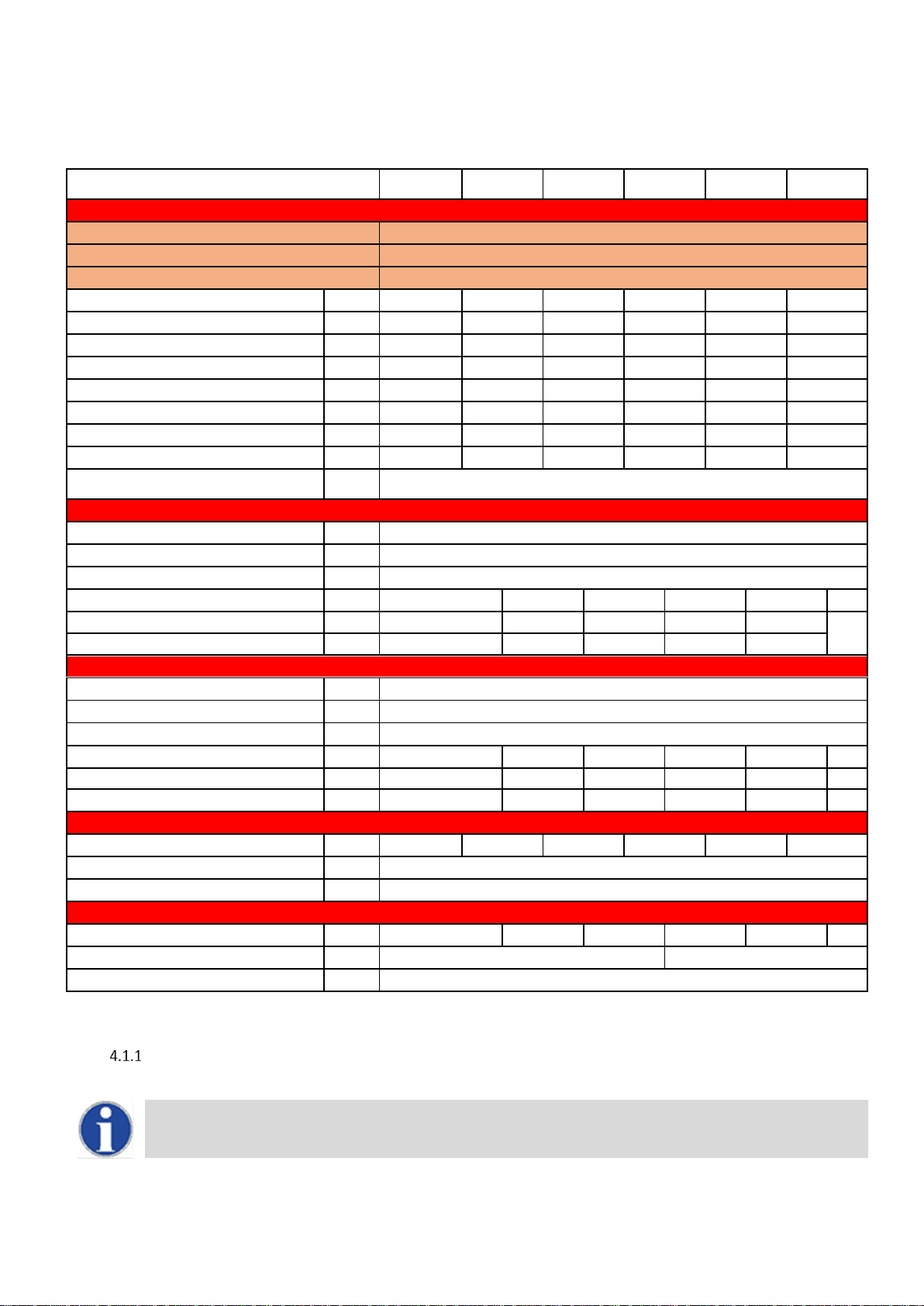
5.0 DIMENSIONS AND CLEARANCE
5.1 DIMENSIONS
MODEL
TANK VOLUME
HEIGHT
WIDTH
T&P VALVE
COLD FEED
HOT OUTLET
A B C D E
SHW35-245
244
1530
715
755
1610
1610
SHW46-325
325
1920
715
1117
2005
2005
SHW61-325
325
1920
715
1126
2005
2005
SHW86-410
410
1920
865
786
2020
2020
SHW116-410
410
1920
865
786
2020
2020
SHW146-410
410
1920
865
786
2020
2020
DIMENSIONAL DRAWING ECOSHIELD™
Page 12
12
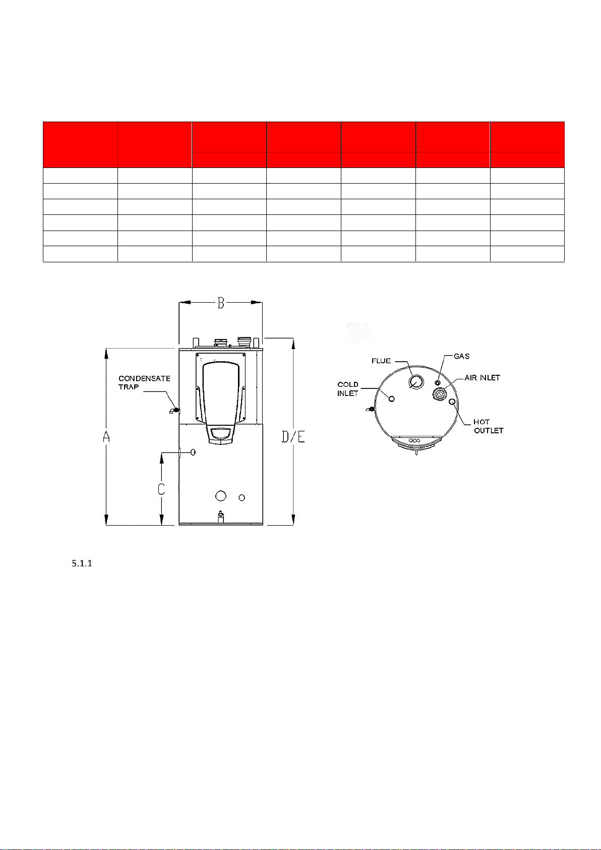
5.2 CLEARANCES
The location chosen for the equipment must permit the provision for a satisfactory flue system and, where necessary, an adequate air supply.
The location must also provide adequate space for servicing and air circulation around each unit. This includes any electrical trunking laid across
the floor and to the appliance.
RECOMMENDED SERVICE CLEARANCES:
TOP - 450mm
LEFT - 600mm
RIGHT - 100mm
FRONT - 600mm
REAR - ZERO
FLUE - 25mm
ENCLOSURE INSTALLATION CLEARANCES (MM)
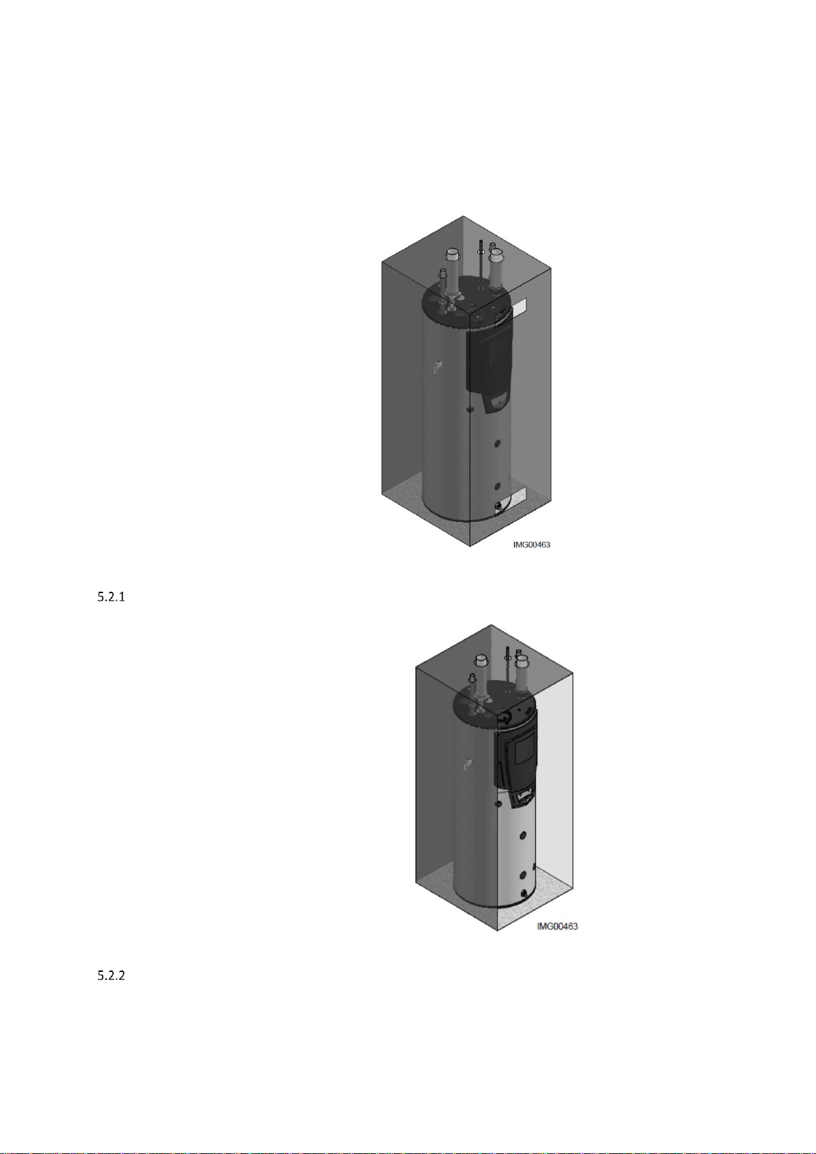
RECOMMENDED SERVICE CLEARANCES:
TOP - 450mm
LEFT - 600mm
RIGHT - 100mm
FRONT - 600mm
REAR - ZERO
FLUE - 25mm
PLANT-ROOM INSTALLATION CLEARANCES (MM)
Further details regarding locations are given in BS5440 or BS6644 as appropriate.
Page 13

13
6.0 GENERAL REQUIREMENTS
The Lochinvar EcoShield™ condensing water heater has been designed to operate trouble free for many years. These instructions should be
followed closely to obtain the maximum usage and efficiency of the equipment.
READ AND UNDERSTAND THE INSTRUCTIONS
Read and fully understand all instructions before attempting to operate maintain or install the unit.
6.1 RELATED DOCUMENTS
It is law that all gas appliances are installed by competent persons, in accordance with The Gas Safety (Installation and Use) Regulations 1998.
Failure to install appliances correctly could lead to prosecution. It is in your own interest, and that of safety, to ensure that this law is complied
with.
The installation of the equipment MUST be in accordance with the relevant requirements of the Gas Safety Regulations, Building Regulations,
I.E.E. Regulations and the bylaws of the local water undertaking. The installation should also be in accordance with any relevant requirements
of the local gas distributor and local authority.
In addition the installation should follow the relevant guidance offered in the following documents. It is not practical to list all relevant information
but emphasis is placed on the following documents, as failure to comply with the guidance given will almost certainly result in an unsatisfactory
installation:
Regulation
Description
BS EN 1858: 2008 + A1: 2011
Chimneys, Components. Concrete flue blocks.
BS 5440-1: 2008
Flueing and ventilation for gas appliances of rated input not exceeding 70 kW net (1st, 2nd and 3rd family gases). Specification for
installation of gas appliances to chimneys and for maintenance of chimneys.
BS 5440-2: 2009
Installation and maintenance of flues and ventilation for gas appliances of rated input not exceeding 70 kW net (1st, 2nd and 3rd
family gases). Specification for installation and maintenance of ventilation for gas appliances.
BS 6644: 2011
Specification for Installation of gas-fired hot water Heaters of rated inputs between 70 kW (net) and 1.8 MW (net) (2nd and 3rd
family gases).
BS EN 806 1-5
Specifications for installations inside buildings conveying water for human consumption.
BS 7671 :2008 + A3:2015
Code of practice for low temperature hot water systems of output greater than 45 kW.
BS 7074: 1989 Parts 1 and 2
Application, selection and installation of expansion vessels and ancillary equipment for sealed systems.
BS 7671: 2008 + A1: 2011
Requirements for electrical installations, I.E.E. wiring regulations seventeenth edition.
BS 7671: Amendment 2: August 2013
BS EN 12828:2012+A1:2014
Heating systems in buildings. Design for water-based heating systems.
CP 342 (Part 2 1974):
Code of practice for centralised hot water supply-buildings other than dwellings.
Institute of Gas Engineers and Managers (IGEM) Publications
IGE/UP/1 - Edition 2:
Installation pipework on industrial and commercial premises.
IGE/UP/2 – Edition 3
Gas installation pipework, boosters and compressors on industrial and commercial premises.
IGE/UP/4 - Edition 4
Commissioning of gas-fired plant on industrial and commercial premises.
IGE/UP/10 - Edition 4
Installation of flued gas appliances in industrial and commercial premises.
Gas Safety (Installation and Use) Regulations 1998
CIBSE: Guides
Part A Environmental Design
Part G Public health engineering
H.S.E. guidance
INDG 436 Safe management of industrial steam & hot water Heaters
SAFED BG01Guidance on safe operation of Water Heaters
Third edition of the 1956 Clean Air Act Memorandum on Chimney Heights
Manufacturer's notes must not be taken in any way as overriding statutory obligations.
Page 14

14
7.0 WATER QUALITY
Water supply quality may adversely affect the efficiency performance and longevity of Water Heaters and Hot Water systems. Hard water may
cause the formation of limescale which will reduce operating efficiency and may cause early product failure. Please note the following:-
Water Hardness – should not exceed 205ppm CaCO3 and Total Dissolved Solids (TDS) of untreated water should not exceed
350ppm.
If these values are exceeded a water treatment specialist should be consulted. Water Softeners and Water Conditioners may be
considered, but whichever method is selected, it should be suitable for installation with Direct Gas-fired Water Heaters. A maintenance
regime will also be required for such systems
High hot water temperature and high demand for hot water is likely to cause quicker limescale formation
The formation of limescale or other solids can cause a blockage within the heat exchanger, which in turn may cause
premature failure. Such instances are not regarded as defects in manufacture and will not be covered under the
product warranty.
8.0 LOCATION
8.1 PLANT ROOM REQUIREMENTS
The Lochinvar EcoShield™ may only be installed in a room that complies with the appropriate ventilation requirements.
The Lochinvar EcoShield™ can be used as a type C13, C33, or C53 appliance. Due to its room sealed design, ventilation allowances for
combustion air are not necessary, provided the minimum clearances and service clearances as detailed in 5.2 are observed. If the appliance is
to be installed in a compartment or a hot environment, the minimum clearances detailed in 5.2.1 should be observed. In addition to this or to
comply with the recommendations in BS6644, ventilation for cooling purposes must be fitted. For further guidance, please refer to Section 11.0
or to BS5440-2 or BS6644 as appropriate.
The Lochinvar EcoShield™ can also be used as a type B23 appliance. If such a configuration is to be used, then appropriate ventilation for
cooling and combustion must be provided. For further details, please refer to Section 9 AIR SUPPLY or to BS5440-2 or BS6644 as appropriate.
8.2 GENERAL REQUIREMENTS
Corrosion of the heat exchanger and flue system may occur if air for combustion contains certain chemical vapours. Such corrosion may result
in poor combustion and create a risk of asphyxiation. Aerosol propellants, cleaning solvents, refrigerator and air condition ing refrigerants,
swimming pool chemicals, calcium and sodium chloride, waxes and process chemicals are corrosive. Products of this sort should not be stored
near the water heater or outside by the air intake (if applicable). The fitting of this equipment in a situation where aeros ols or other chemicals
may be entrained into the combustion air will invalidate the warranty.
The equipment must be installed on a level surface that is capable of adequately supporting its weight (when filled with water) and any ancillary
equipment. The operation of the equipment must not cause the temperature of any combustible material in the vicinity of the equipment and its
flue to exceed 65°C. If such a situation is unavoidable, appropriate insulation should be provided.
Locate the equipment so that if the appliance or any connecting pipework should leak, water damage will not occur.
When such locations cannot be avoided a suitable drain pan should be installed under the equipment. The pan should
be adequately drained but must not restrict the combustion or ventilation airflow.
8.3 CONDENSATE DRAIN
The condensate drain is located on the left hand side of the water heater. It is fitted with a ½” PVC tee and union, this should be connected to
an appropriate condensate drain, sloping continuously away from the water heater at an angle of at least 3 (50mm per metre).
The Water Resources Act requires that trade effluent is discharged to municipal sewers between pH 6.5 and 10.0. If it is determined that these
levels cannot be achieved, an in-line condensate neutralisation kit is available from Lochinvar Limited. This unit is capable of neutralising 4000
litres of condensate to a pH of 7.0 before releasing it to a drain.
Page 15

15
9.0 GAS SUPPLY
The Lochinvar EcoShield™ range is suitable for use on second and third family gasses 2H - G20 - 20mbar and 3P - G31 - 37mbar. Details
relating to Natural Gas (2H) appear below; for details relating to Propane (3P) please refer to Section 16.0 LPG FUEL.
9.1 SERVICE PIPES
The local gas distributor must be consulted at the installation planning stage in order to establish the availability of an adequate supply of gas.
An existing service pipe must not be used without prior consultation with the local gas distributor.
9.2 METERS
A new gas meter will be connected to the service pipe by the local gas distributor contractor. An existing gas meter should be checked, preferably
by the gas distributor, to ensure that it is adequate to deal with the rate of gas supply required.
9.3 GAS SUPPLY PIPES
Supply pipes must be fitted in accordance with IGE/UP/2. Pipework from the meter to the equipment must be of adequate size. The complete
installation must be purged and tested as described in IGE/UP/1. Refer to Section 16.0 LPG Fuel for information on LPG pipework installation
guidance.
9.4 BOOSTED SUPPLIES
Where it is necessary to employ a gas pressure booster, the controls must include a low-pressure cut-off switch at the booster inlet. The local
gas distributor must be consulted before a gas pressure booster is fitted. For details of how to connect a low-pressure cut-off switch, please
refer to Section 11 Electrical Supply
9.5 PLANT-ROOM CONTROL VALVE
A manual valve for plant-room isolation must be fitted in the gas supply line. It must be clearly identified and readily accessible for operation,
preferably by an exit.
9.6 EQUIPMENT GAS SYSTEM LEAK CHECK
An approved gas-inlet appliance isolating valve and union should be installed for each unit in a
convenient and safe position and be clearly marked.
Ensure that the gas-inlet appliance isolating valve is in the OFF position. Although the equipment receives a gas leak check and gas train
component integrity check prior to leaving the factory, transit and installation may cause disturbance to unions, fittings and components. During
commissioning a further test for tightness should be carried out on the equipment gas pipework and components.
Care must be taken not to allow leak detection fluid on or near any electrical parts or
connections.
Page 16

16
10.0 FLUE SYSTEM
All versions of the EcoShield™ Condensing water heater can be installed as either type B23 (fan assisted open flue) or C13, C33, C43,C53,C63
(room sealed) appliances. Only C13,C33,C53 Flue systems are covered in any detail within this document, further information can be found in
the EcoShield™ Flue assemblies and ancillaries guide available at www.lochinvar.ltd.uk See the relevant section for details of each flue type
and requirements.
10.1 FLUE SYSTEM GENERAL REQUIREMENTS
Install the horizontal flue components with an angle of 3° back in the direction of the boiler (roughly equal to five
centimetres for every linear meter). Failure to install the flue correctly will result in a build-up of condense within the
flue pipework that will cause early component failure.
When using a wall terminal, there is the possible risk of ice building-up on surrounding parts/structures, because the
condensate will freeze. This risk should be taken into account during the design phase of the heating installation.
EcoShield™ Water heaters will produce large condense clouds especially during cold weather, consideration must be
taken as to whether this will cause a nuisance to neighbouring properties and if so alternative flue arrangements used.
EcoShield™ Water heaters can operate with very low flue temperatures; as such the flue system used must be suitable
for use with condensing appliances made from either Polypropylene or stainless steel and have a temperature class
of T120.
Aluminium flue pipe must not be used on this appliance as it may lead to premature failure of the heat exchanger and
will invalidate the warranty.
Before installation of any flue system read the installation manual carefully for both the appliance and flue system to
be used. Information on the flue system Supplied by Lochinvar can be found within this manual.
Page 17

17
Model Number
SHW35-245CE
SHW46-325CE
SHW61-325CE
SHW86-410CE
SHW116-410CE
SHW146-410CE
FLUE DATA TYPE B23
Nominal flue diameter (d
nom
)
mm
80
100
Nominal flue diameter (d
outside
)
mm
80 +/-0.3
100 +/-0.3
Nominal flue diameter (d
inside
)
mm
81 +/-0.6
101+/-0.6
Nominal flue diameter (L
insert
)
mm
50 +20/ -2
50 +20/ -2
Maximum flue gas temp.
°C
120
Maximum equivalent length
m
60
Equivalent length 90 bend
mm
1000
Equivalent length 45 bend
mm
500
Flue gas temperature
°C
70
Flue draught requirements
mbar
-0.03 to -0.1
FLUE DATA TYPE C13 & C33
Nominal flue diameter
mm
80/125
100/150
Maximum flue gas temp.
°C
120
Maximum equivalent length
m
30
13
Equivalent length 90 bend
mm
1000
Equivalent length 45 bend
mm
500
FLUE DATA TYPE C43 & C53
Nominal flue diameter (d
nom
)
mm
80
100
Nominal flue diameter (d
outside
)
mm
80 +/-0.3
100 +/-0.3
Nominal flue diameter (d
inside
)
mm
81 +/-0.6
101+/-0.6
Nominal flue diameter (L
insert
)
mm
50 +20/ -2
50 +20/ -2
Minimum flue gas temp
°C
35
Average flue gas temp
°C
70
Maximum flue gas temp.
°C
120
Maximum equivalent length
m
60*
Equivalent length 90 bend
mm
1000
Equivalent length 45 bend
mm
500
FLUE DATA TYPE C63
Nominal flue diameter (d
nom
)
mm
80
100
Nominal flue diameter (d
outside
)
mm
80 +/-0.3
100 +/-0.3
Nominal flue diameter (d
inside
)
mm
81 +/-0.6
101+/-0.6
Nominal flue diameter (L
insert
)
mm
50 +20/ -2
50 +20/ -2
Minimum flue gas temp
°C
35
Average flue gas temp
°C
70
Maximum flue gas temp.
°C
120
Max combustion air temperature
°C
40
Maximum equivalent length
m
48
FLUE SYSTEM TECHNICAL DATA TABLE
* On twin pipe systems, the maximum equivalent length is the sum of the air inlet components and the exhaust components.
Page 18
18
10.2 FLUE DISCHARGE
The flue system must ensure safe and efficient operation of the equipment to which it is attached, protect the combustion process from wind
effects and disperse the products of combustion to open external air.
The flue must terminate in a freely exposed position and be so situated as to prevent the products of combustion entering any opening in a
building. For installations with a total output above 333kW nett, the clean air act should be consulted and complied with.
Under certain operating and weather conditions, the EcoShield™ water heater may generate a plume at the terminal. Consideration should be
given to the nuisance this may cause and the terminal should be sited accordingly.
For further information on terminal locations, please refer to Section 10.3.1 FLUE TERMINAL POSITIONS.
10.3 CONDENSATE DRAIN
If the flue system rises at an angle of at least 3 (50mm per metre), no additional condensate drain will be required. Failure to provide an
adequate rise in the flue system may lead to pooling of condensate which may lead to premature failure of the flue system.
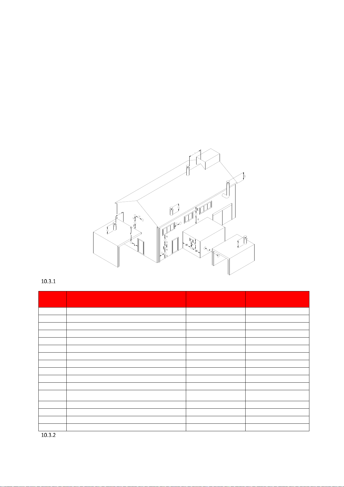
FLUE TERMINAL POSITIONS
Location
Description
SHW35-245CE
SHW46-325CE
SHW61-325CE
SHW86-410CE
SHW116-410CE
SHW146-410CE
A
Directly below an opening, air brick, opening windows etc.
300
2000
B
Above an opening, air brick, opening windows etc.
300
1000
C
Horizontally to an opening, air brick, opening windows etc.
300
1000
D
Below a gutter or sanitary pipework
75
75
E
Below the eaves
200
200
F
Below a balcony or car port roof
200
200
G
From a vertical drain or soil pipe
150
150
H
From an internal or external corner
300
300
I
Above ground, roof or balcony level
300
300
J
From a surface facing the terminal
600
1000
K
From a terminal facing the terminal
1200
2000
L
From an opening in the car port (e.g. door, window) into the
dwelling
1200
1200
M
Vertically from a terminal on the same wall
1500
1500
N
Horizontally from a terminal on the same wall
300
600
P
From a vertical structure on the roof
300
300
Q
Above intersection with the roof
300
300
FLUE TERMINAL MINIMUM DISTANCES
Page 19

19
10.4 FLUE SYSTEM GENERAL REQUIREMENTS
Detailed recommendations for the flue system are given in BS5440-1 for equipment of rated input not exceeding 70kW net, BS6644 for
equipment above 70kW net and IGE/UP/10 for equipment of rated input above 54kW net. The following notes are intended to give general
guidance only.
10.5 APPROVED FLUE SYSTEM
For Concentric and Twin pipe flue systems only the Lochinvar supplied M&G flue system must be used
The approved flue system is not suitable for use external to the building. If external routes cannot be avoided, a flue
system manufacturer should be consulted to supply a suitable alternative.
10.6 INSTALLATION PRECAUTIONS
The approved flue system is rated to 120C max. To prevent the exhaust temperature exceeding this, the appliance is supplied with
a flue gas temperature sensor.
This must be fitted during the installation of the flue system. Failure to do so may lead to severe
personal injury, death or substantial property damage.
The water heater must not be operated unless the complete flue system is installed. This includes the water heater connections,
concentric adaptor (if required) flue pipes, air ducts (if required) and terminals. If discharging at low level, a suitable flue guard must
be installed.
During assembly precaution should be taken to ensure that the internal sealing ring is seated correctly.
Due to the close tolerances in the flue system, it may be necessary to use a twisting action to fit the joints together. No lubrication
other than water should be used.
10.7 CONDENSATE DRAIN
Condensate can flow back to the appliance, this will travel through the heat exchanger into the condensate drain via the trap.
If the flue system rises at an angle of at least 3 (50mm per metre), no additional condensate drain will be required. Failure to provide an
adequate rise in the flue system may lead to pooling of condensate which may lead to premature failure of the flue system.
10.8 TYPE B
23
CONVENTIONAL FANNED FLUE
When the heater is installed as a Type B23 appliance, the flue system should be installed in accordance with the flue manufacturer’s specific
instructions. A kit of components is available to facilitate conventional flueing of the EcoShield™ water heater;
This must be fitted prior to any other flue pipework.
SHW35-245CE –SHW61-325CE kit number SHCF003
SHW86-410CE –SHW145-410CE kit number SHCF004
Page 20
20
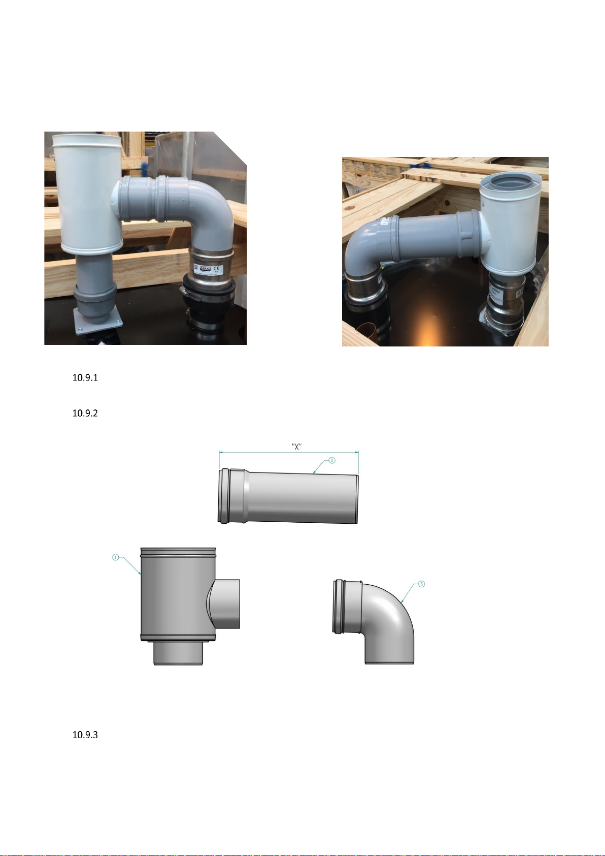
10.9 ROOM SEALED (TYPE C) FLUE ASSEMBLY
Before fitting the flue system for either type C13 Horizontal or C53 Vertical Concentric flue the flue transition kit should be installed to the top of
the heater as per 10.9.3 and 10.9.7
SHW35-245,SHW46-325,SHW61-325
SHW86-410,SHW116-410,SHW146-410
ECOSHIELD™ SHOWING TRANSITION KIT FITTED
TRANSITION KIT SHW35-245CE – SHW61-325CE
FLUE TRANSITION DETAILS SHW35-245CE – SHW61-325CE
Page 21
21
ITEM
DESCRIPTION
1
CONCENTRIC ADAPTER
2
EXTENSION
3
ELBOW
FLUE CONNECTION DETAILS SHW35-245CE - SHW61-325CE
MODEL
“X” DIMENSION
SHW35-245 NG CE
115mm
SHW46-325 NG CE
195mm
SHW61-325 NG CE
No cut required
EXTENSION LENGTH SHW35-245 CE - SHW61-325 CE
To install the flue connection to the SHW35-245CE - SHW61-325CE water heaters the following procedure should be followed:
1. Insert the air intake transition into the intake connection reducer and tighten the worm drive clip.
2. Fit 80mm elbow (Item 3 in Table) to cut end of extension.
3. To the side (intake) connection of the concentric adaptor (Item 1 in Table), fit the other end of the 80mm dia. Extension.
4. Fit the bottom (flue) connection of the concentric adapter to the flue connection on the heater.
.
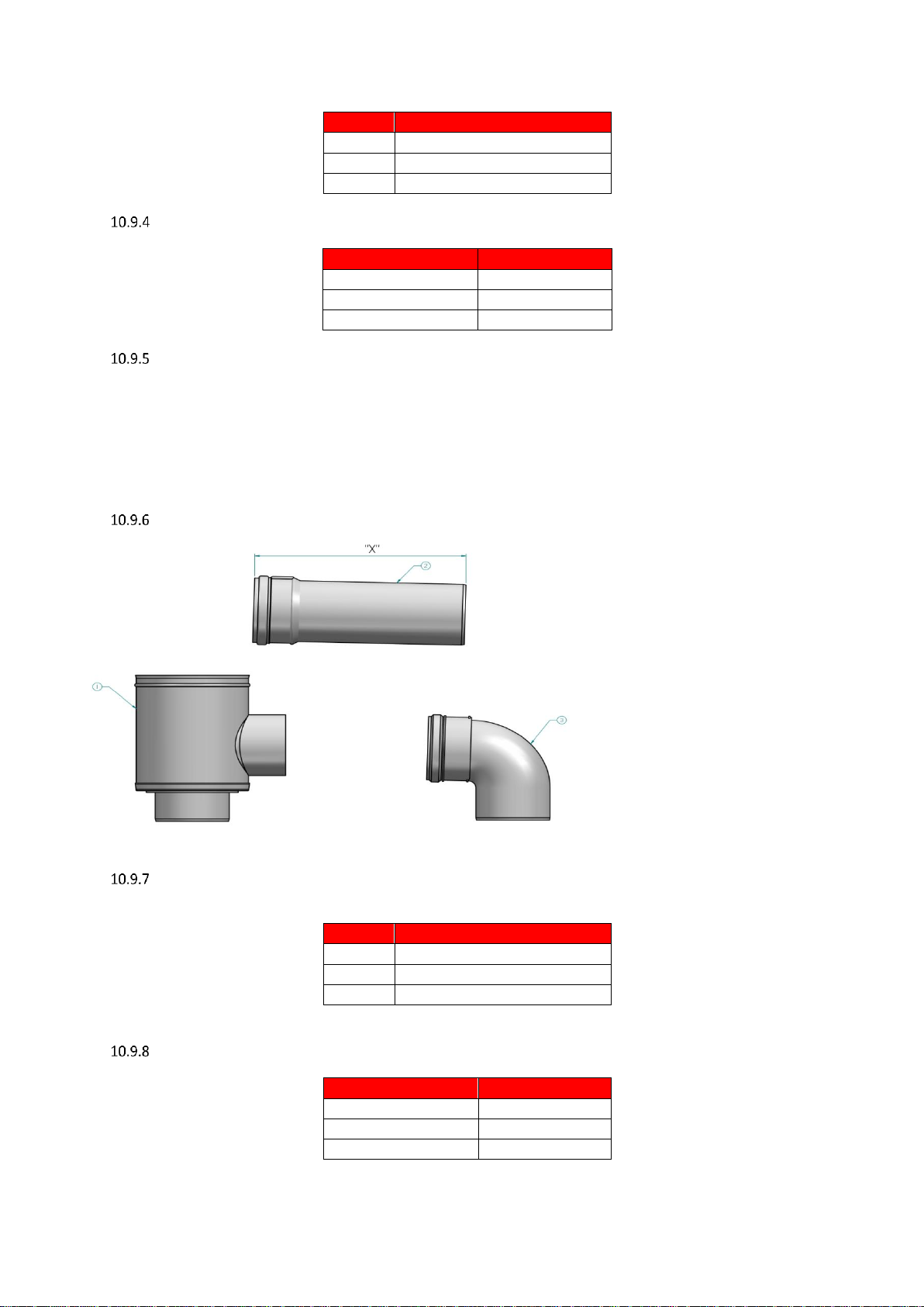
TRANSITION KIT SHW86-410CE, SHW116-410CE & SHW146-410CE
FLUE TRANSITION DETAILS SHW86-410CE - SHW146-410CE
ITEM
DESCRIPTION
1
CONCENTRIC ADAPTER
2
EXTENSION
3
ELBOW
FLUE CONNECTION DETAILS SHW86-410CE - SHW146-410CE
MODEL
“X” DIMENSION
SHW86-410 NG CE
135mm
SHW116-410 NG CE
No cut required
SHW146-410 NG CE
No cut required
Page 22

22
To install the flue connection to the SHW86-410 CE – SHW146-410 CE water heaters the following procedure should be followed:
1. Insert the air intake transition into the intake connection reducer and tighten the worm drive clip.
2. Fit 100mm elbow (Item 3 in 10.9.7) to cut end of extension.
3. To the side (intake) connection of the concentric adaptor (Item 1 in 10.9.7), fit the other end of the 100mm dia. Extension.
4. Fit the bottom (flue) connection of the concentric adapter to the flue connection on the heater.
10.10 C13 CONCENTRIC HORIZONTAL FLUE SYSTEMS
Flue system specifications
MANUFACTURER MUELINK AND GROL (M&G)
TEMPERATURE CLASS T120
FLUE GAS MATERIAL PP
Each concentric horizontal flue kit includes the items shown in the tables below
Item No SHHF003
CONCENTRIC HORIZONTAL FLUE ASSEMBLY MODELS
SHW35-245,SHW46-325,SHW61-325
COMPONENTS INCLUDED
Item No.
Description
Included
M86934
CONCENTRIC HORIZONTAL TERM Ø80/125mm PP (NO WALL PLATES)
1
M28925
TERMINAL WALL PLATES (PAIR)
1
M121602
TWIN PIPE TO CONCENTRIC ADAPTOR Ø80/80mm TO Ø80/125mm PP
1
M75256
AIR INLET TRANSITION Ø80mm ALU
1
M84471
SAMPLING POINT Ø80/125mm PP
1
M84460
CONCENTRIC BEND 90° Ø80/125mm PP
1
Item No SHHF004
CONCENTRIC HORIZONTAL FLUE ASSEMBLY MODELS
SHW86-410,SHW116-410,SHW146-410
COMPONENTS INCLUDED
Item No.
Description
Included
LV310758
CONCENTRIC HORIZONTAL TERMINAL Ø100/150mm PP
1
M75257
AIR INLET TRANSITION Ø100mm ALU
1
M121605
TWIN PIPE TO CONCENTRIC ADAPTOR Ø100/100mm TO Ø100/150mm PP
1
M84421
SAMPLING POINT Ø100/150mm PP
1
M84412
CONCENTRIC BEND 90° Ø100/150mm PP
1
Page 23

23
10.11 HORIZONTAL FLUE TERMINAL INSTALLATION
When the Water Heater is installed as a Type C13 (Horizontal concentric) appliance, the flue system should be installed as follows:
1. Determine the location of the flue terminal, taking into account minimum distances as detailed in 10.3.1 and the relevant British
Standards.
2. Taking care to protect the appliance from debris and dust, drill a hole in the desired location. The diameter of the hole should be no
more than 10mm greater than the diameter of the air supply pipe of the terminal.
3. Determine the required length of the terminal and cut as necessary.
When determining the required length for the flue terminal, the outer wall plate or rosette should be flush to the wall.
(see 10.11.1 )
Once cut; remove all burrs and sharp edges
4. Insert the terminal into the drilled hole. The terminal section should be installed level or with a fall to outside (Max. 10mm per metre)
to prevent the ingress of water.
When inserting the terminal, ensure the air intake section is at the bottom.
5. Fill the void between the terminal and wall with water resistant sealant.
6. Fit the wall plates or rosette using appropriate fixings.
7. Install the remainder of the flue system working progressively away from the Water Heater supporting the pipes as necessary.
HORIZONTAL TERMINAL INSTALLATION
10.12 FLUE TERMINAL GUARDING
If a horizontal flue terminal is to be fitted less than 2 metres from ground level or in a location where it can be touched from a window, door or
balcony, a terminal guard must be fitted.
Page 24

24
10.13 C33 CONCENTRIC VERTICAL FLUE SYSTEMS
Flue system specifications
MANUFACTURER MUELINK AND GROL (M&G)
TEMPERATURE CLASS T120
FLUE GAS MATERIAL PP
Each concentric Vertical flue kit includes the items shown in the tables below
Item No SHVF003
CONCENTRIC VERTICAL FLUE ASSEMBLY MODELS
SHW35-245,SHW46-325,SHW61-325
COMPONENTS INCLUDED
Item No.
Description
Included
M75256
AIR INLET TRANSITION Ø80mm ALU
1
M121602
TWIN PIPE TO CONCENTRIC ADAPTOR Ø80/80mm TO Ø80/125mm PP
1
M84471
SAMPLING POINT Ø80/125mm PP
1
M86864
CONCENTRIC VERTICAL TERMINAL Ø80/125mm PP
1
Item No SHVF004
CONCENTRIC HORIZONTAL FLUE ASSEMBLY MODELS
SHW86-410,SHW116-410,SHW146-410
COMPONENTS INCLUDED
Item No.
Description
Included
M75257
AIR INLET TRANSITION Ø100mm ALU
1
M121605
TWIN PIPE TO CONCENTRIC ADAPTOR Ø100/100mm TO Ø100/150mm PP
1
M84421
SAMPLING POINT Ø100/150mm PP
1
LV310754
CONCENTRIC VERTICAL TERMINAL Ø100/150mm PP
1
10.14 VERTICAL FLUE TERMINAL INSTALLATION
When the water heater is installed as a Type C33 appliance, the flue system should be installed as follows:
1. Confirm that the roof flashing is correct for the type of roof through which the terminal is to be installed. Section 10.14.1
2. Determine the desired location for the flue terminal, taking into account minimum distances as detailed in Section 10.3.1 TERMINAL
POSITIONS and the relevant British Standards.
3. Taking care to protect the appliance from debris and dust, drill a hole in the desired location. The diameter of the hole should be no
more than 10mm greater than the diameter of the air supply pipe of the terminal.
The hole should be drilled from the outside to ensure that no damage is done to the roofing material. Extra care
should be taken to ensure that the hole is drilled vertically.
4. Install the roof flashing and secure as appropriate.
5. Carefully insert the roof terminal through the roof flashing and hole in the roof.
Page 25

25
When inserting the roof terminal do not support or turn the terminal using the cap.
6. Ensure the terminal is vertical using a spirit level.
7. Fit the support bracket around the terminal and secure using appropriate fixings. Do not tighten the support bracket
8. Install the remainder of the flue system working progressively away from the water heater supporting the pipes as necessary.
9. Once the flue system is fully installed, tighten the clamp to secure the terminal in place.
VERTICAL TERMINAL ROOF FLASHINGS FOR SYNTHETIC, FLAT AND TILED ROOFS
INSTALLING TERMINAL THROUGH ROOF FLASHING
Page 26

26
GENERAL CONCENTRIC FLUE SYSTEM INSTALLATION GUIDELINES
The information in this section is for General guidance only and may not fully represent the installation on site
Do not drill and screw
into flue system
Page 27

27
Max distance between
brackets
Page 28

28
Page 29

29
Page 30

30
10.15 C
43
COMMON VENTED FLUE SYSTEMS IN MULTI FLOOR BUILDINGS
In C43 systems water heaters are fitted on common air inlet and flue gas outlet (either concentric or parallel) systems in multiple floor buildings.
Only use a C43 venting system when the common duct is a natural draught chimney. The
common duct is part of the building, not a part of the system.
CONDENSATE DRAIN
Condensate can flow back to the appliance, this will travel through the heat exchanger into the condensate drain via the trap.
If the flue system rises at an angle of at least 3 (50mm per metre), no additional condensate drain will be required. Failure to provide an
adequate rise in the flue system may lead to pooling of condensate which may lead to premature failure of the flue system.
Page 31

31
10.16 C
53
(TWIN PIPE) FLUE SYSTEMS
Flue system specifications
MANUFACTURER MUELINK AND GROL (M&G)
TEMPERATURE CLASS T120
FLUE GAS MATERIAL PP
Each Twin-Pipe starter assembly includes the items shown in the tables below, you then add either the Vertical or Horizontal terminal and air
inlet.
Item No SHTF003
TWIN-PIPE FLUE STARTER ASSEMBLY MODELS
SHW35-245,SHW46-325,SHW61-325
COMPONENTS INCLUDED WITHIN KIT TO START INSTALLATION
Item No.
Description
Included
M75256
AIR INLET TRANSITION Ø80mm ALU
1
M85279
SAMPLING POINT Ø80mm PP
1
VERTICAL FLUE
M86864
CONCENTRIC VERTICAL TERMINAL Ø80/125mm PP
LV305016
HORIZONTAL AIR INLET Ø80mm
HORIZONTAL FLUE
M86934
CONCENTRIC HORIZONTAL TERMINAL Ø80/125mm PP (NO WALL PLATES)
LV305016
HORIZONTAL AIR INLET Ø80mm
M28925
TERMINAL WALL PLATES (PAIR)
Item No SHTF004
TWIN-PIPE FLUE STARTER ASSEMBLY MODELS
SHW86-410,SHW116-410,SHW146-410
COMPONENTS INCLUDED WITHIN KIT TO START INSTALLATION
Item No.
Description
Included
M75257
AIR INLET TRANSITION Ø100mm ALU
1
M85189
SAMPLING POINT Ø100mm PP
1
VERTICAL FLUE
LV310754
CONCENTRIC VERTICAL TERMINAL Ø100/150mm PP
LV305039
HORIZONTAL AIR INLET Ø100mm ALU
HORIZONTAL FLUE
M86934
CONCENTRIC HORIZONTAL TERMINAL Ø80/125mm PP (NO WALL PLATES)
LV305039
HORIZONTAL AIR INLET Ø100mm ALU
M28925
TERMINAL WALL PLATES (PAIR)
When installing EcoShield™ on a C53 twin pipe flue system, the Lochinvar Twin pipe flue starter assembly must be fitted first.
Page 32

32
When installing the water heater as a Type C53 appliance, it should be noted that the terminals must not be
installed on opposite sides of the building.
If the flue temperature sensor is not fitted, the flue gas temperature may exceed the maximum
temperature rating of the flue and can lead to severe personal injury, death or substantial property
damage.
To install a Type C53 terminal or air inlet, the procedure for either a Type C13 (horizontal) or a Type C33 (vertical) terminal should
be followed noting that the annular space of the terminal should be sealed off.
Page 33

33
GENERAL TWIN-PIPE INSTALLATION GUIDELINES
The information in this section is for General guidance only and may not fully represent the installation on site
Page 34

34
Page 35

35
10.17 FLUE TERMINAL GUARDING
If a horizontal flue terminal is to be fitted less than 2 metres from ground level or in a location where it can be touched from a window, door or
balcony, a terminal guard must be fitted.
The terminal guard is constructed from plastic-coated mild steel and is suitable for use on condensing appliances only. The guard should be
installed centrally around the terminal ensuring a gap of at least 50mm between the guard and terminal is maintained.
Page 36

36
10.18 TYPE B
23
(CONVENTIONAL FLUE WITH FAN ASSISTANCE)
Item No SHCF003
CONVENTIONAL FLUE ASSEMBLY
MODELS SHW35-245,SHW46-325,SHW61-325
COMPONENTS REQUIRED TO START INSTALLATION
Item No.
Description
Included
M75256
AIR INLET TRANSITION Ø80mm ALU
1
M73039
AIR INLET GRILLE Ø80mm ALU
1
M85279
SAMPLING POINT Ø80mm PP
1
Item No SHCF004
CONVENTIONAL FLUE ASSEMBLY MODELS
SHW86-410,SHW116-410,SHW146-410
COMPONENTS REQUIRED TO START INSTALLATION
Item No.
Description
Included
M75257
AIR INLET TRANSITION Ø100mm ALU
1
M86787
APPLIANCE AIR INLET GUARD Ø100mm
1
M85189
SAMPLING POINT Ø100mm PP
1
The above is a kit of components to facilitate conventional flueing of the appliance and must be fitted prior to fitting any other flue components.
Page 37

37
10.19 C
63
CERTIFIED FLUE SYSTEMS
In general, Water heaters are certified with their own purpose supplied Concentric or Twin Pipe flue systems, C63 certified appliances allow the
installer to use other flue systems when installing the Water heater however, they must be of a suitable minimum standard as per Table below.
CE string
flue gas
material
European standard
Tempera
-ture
class
Pressure
class
Resistance to
condensate Corrosion
resistance
class
Metal: liner
specification
s
Soot fire
resistance
class
Distance to
combustible
material
Plastics:
location
Plastics: fire
behaviour
Plastics:
enclosure
Min required PP
EN 14471
T120
P1 W 1 O
30
I of E
C/E
L
Min required
Inox
EN 1856-1
T120
P1 W 1
L20040
O
40
C63 FLUE SYSTEM SPECIFICATION
Twin-pipe Flue Systems
Material
Water heater
d
nom
D
outside
d
inside
L
insert
PP
SHW35-SHW61
80
80 +/-0.3
81 +/-0.6
50 +20/ -2
PP
SHW86-SHW146
100
100 +/-0.3
101+/-0.6
50 +20/ -2
Concentric Flue Systems
Material
Water heater
d
nom
D
outside
d
inside
L
insert
PP
SHW35-SHW61
80/100
80 +/-0.3-124 +0.5/-1
81 +/-0.6-125.5 +1/-0.5
56 +/-3
PP
SHW86-SHW146
100/150
100 +/-0.3 - 148.5 +0.5/-1
101+/-0.5 - 150+1/-0.5
50 +20/ -2
When installing the water heater as a Type C63 appliance, it should be noted that the terminals
must not be installed on opposite sides of the building.
The maximum allowable recirculation rate is 10% under wind conditions
Aluminium flue pipe must not be used on this appliance as it may lead to premature failure of the
heat exchanger and will invalidate the warranty.
CONDENSATE DRAIN
Condensate can flow back to the appliance, this will travel through the heat exchanger into the condensate drain via the trap.
If the flue system rises at an angle of at least 3 (50mm per metre), no additional condensate drain will be required. Failure to provide an
adequate rise in the flue system may lead to pooling of condensate which may lead to premature failure of the flue system.
Model Number
SHW35-245CE
SHW46-325CE
SHW61-325CE
SHW86-410CE
SHW116-410CE
SHW146-410CE
FLUE DATA TYPE C
63 WITH TWIN-PIPE FLUE
Minimum flue gas temp
°C
35
Average flue gas temp
°C
70
Maximum flue gas temp
°C
120
Maximum equivalent length
m
48
Model Number
SHW35-245CE
SHW46-325CE
SHW61-325CE
SHW86-410CE
SHW116-410CE
SHW146-410CE
FLUE DATA TYPE C
63 WITH CONCENTRIC FLUE
Minimum flue gas temp
°C
35
Average flue gas temp
°C
70
Maximum flue gas temp
°C
120
Maximum equivalent length
m
24
10
Page 38

38
11.0 AIR SUPPLY
The following information is based on single water heater installations only. If more than one water heater is being used, BS6644 should be
consulted to calculate the necessary requirements.
11.1 COMBUSTION VENTILATION
When used as a Type C appliance, provided sufficient clearance is provided, ventilation for combustion is not necessary as the combustion air
is ducted directly from outside.
When used as a Type B appliance, the combustion air requirements are as follows:
Model
Gross
Input
(kW)
Net
Input
(kW)
Ventilation
(Room)
(cm2)
Compartment
Compartment
(Direct to Outside)
(To Internal Space)
High
(cm2)
Low
(cm2)
High
(cm2)
Low
(cm2)
SHW35-245CE
36.6
33.3
132
166
332
332
664
SHW46-325CE
43.9
39.6
165
200
400
400
800
SHW61-325CE
58.6
52.8
230
265
530
530
1060
COMBUSTION VENTILATION REQUIREMENTS SHW35-245CE – SHW61-325CE
Model
Gross
Input
(kW)
Net
Input
(kW)
Plant Room
Enclosure
Low
Summer Use
Medium
Summer Use
High
Summer Use
Low
Summer Use
Medium
Summer Use
High
Summer Use
High
(cm2)
Low
(cm2)
High
(cm2)
Low
(cm2)
High
(cm2)
Low
(cm2)
High
(cm2)
Low
(cm2)
High
(cm2)
Low
(cm2)
High
(cm2)
Low
(cm2)
SHW86-410CE
83.5
75.3
152
304
228
380
304
456
380
760
456
836
532
912
SHW116-410CE
117.2
105.6
212
424
318
530
424
636
530
1060
636
1166
742
1272
SHW146-410CE
146.5
132.0
264
528
396
660
528
792
660
1320
792
1452
924
1584
COMBUSTION VENTILATION REQUIREMENTS SHW86-410CE – SHW146-410CE
11.2 COOLING VENTILATION
When used as a type C appliance, cooling ventilation should be provided as follows:
Model
Input
(Gross)
kW
Input
(Net)
kW
Enclosure/Compartment
Enclosure/Compartment
Internal Space/Boiler Room
(Direct to Outside)
(To Internal Space)
High
(cm2)
Low
(cm2)
High
(cm2)
Low
(cm2)
High
(cm2)
Low
(cm2)
SHW35-245CE
36.6
33.2
166
166
332
332
N/A
N/A
SHW46-325CE
43.9
39.6
200
200
400
400
N/A
N/A
SHW61-325CE
58.6
52.8
265
265
530
530
N/A
N/A
SHW86-410CE
83.5
75.3
380
380
760
760
152
152
SHW116-410CE
117.2
105.6
530
530
1060
1060
212
212
SHW146-410CE
146.5
132.0
660
660
1320
1320
264
264
COOLING VENTILATION REQUIREMENTS
When used as a type B appliance, provision for cooling ventilation is included in the combustion ventilation allowance.
Page 39

39
12.0 WATER CONNECTIONS
12.1 GENERAL
Recommendations for the water circulation system are given in BS6644 and CP 342. The following notes are of particular importance.
1. Circulating pipework not forming part of the useful heating surface should be insulated. Cisterns, expansion vessels and pipework
situated in areas exposed to freezing conditions should also be insulated.
2. Drain valves must be located in accessible positions that will permit draining of the entire system including the unit and any additional
storage vessel.
3. Tapping sizes for connection to the water system are detailed in 4.1.1Technical Data
4. Ideally, individual valves should be fitted to each unit to enable isolation from the system. The arrangement must comply with the
requirements of BS6644.
5. Typical pipework schematics are available from Lochinvar Limited upon request.
12.2 OPEN VENTED SYSTEM ARRANGEMENT
The Lochinvar EcoShield™ can be used in an open vented arrangement provided that a vent pipe in accordance with CP 342, BS6644 or
BS6700 as appropriate is fitted. The minimum static head requirement for an open vented system is 1.0 bar.
OPEN VENTED SYSTEM INSTALLATION SCHEMATIC
Page 40

40
12.3 UNVENTED SYSTEM ARRANGEMENT
It is the law that unvented hot water systems be installed by an approved installer.
If the Lochinvar EcoShield™ is to be used in an unvented arrangement, the system should follow the guidance given in BS6700 and must comply
with the Building Regulations 1992: Part G3, in England and Wales,P5 in Northern Ireland and P3 in Scotland. A kit of components that
have been suitably sized for the unvented operation of the appliance is available from Lochinvar Limited. For further inform ation, contact
Lochinvar Limited.
UN-VENTED SYSTEM INSTALLATION SCHEMATIC
Page 41

41
TEMPERATURE AND PRESSURE RELIEF VALVE
A temperature and pressure relief valve is factory fitted as part of the unvented water system kit. This valve has a lift pressure of 7 bar and a lift
temperature of 90°C.
This should be checked for transit damage prior to filling the water heater.
The storage vessel relief valve connection should not be used for any other purpose.
RELIEF VALVE DISCHARGE PIPEWORK
It is important that any discharge water does not collect in the discharge pipe-work and can run freely to the tundish. The tundish should be
mounted in a vertical and visible position located in the same space as the unvented hot water storage system and be fitted as close as possible
and within 500mm of the safety device e.g. the temperature relief valve.
The discharge pipe from the tundish should terminate in a safe place where there is no risk to persons in the vicinity of the discharge, be of metal
and:
a) Be at least one pipe size larger than the nominal outlet size of the safety device unless its total equivalent hydraulic resistance exceeds
that of a straight pipe 9m long i.e. discharge pipes between 9m and 18m equivalent resistance length should be at least two sizes
larger than the nominal outlet size of the safety device, between 18 and 27m at least 3 sizes larger, and so on. Bends must be taken
into account in calculating the flow resistance.
An alternative approach for sizing discharge pipes would be to follow BS6700 Specification for design installation, testing and maintenance of
services supplying water for domestic use within buildings and their curtilages.
b) Have a vertical section of pipe at least 300mm long, below the tundish before any elbows or bends in the pipework.
c) Be installed with a continuous fall.
d) Have discharges visible at both the tundish and the final point of discharge but where this is not possible or is practically difficult there
should be clear visibility at one or other of these locations.
Examples of acceptable discharge arrangements are:
I. Ideally below the fixed grating and above the water seal in a trapped gulley.
II. Downward discharges at a low level; i.e. up to 100mm above external surfaces such as car parks, hard standings, grassed areas etc.
are acceptable providing that where children play or otherwise come into contact with discharges, a wire cage or similar guard is
positioned to prevent contact whilst maintaining visibility.
III. Discharges at a high level; e.g. into a metal hopper and metal down pipe with the end of the discharge pipe clearly visible (tundish
visible or not) or onto a roof capable of withstanding high temperature discharges of water and 3m from any plastic guttering systems
that would collect such discharges (tundish visible).
IV. Where a single pipe serves a number of discharges, such as in blocks of flats, the number served should be limited to not more than
6 systems so that any installation can be traced reasonably easily. The single common discharge pipe should be at least one pipe size
larger than the largest individual discharge pipe to be connected. If unvented hot water storage systems are installed where discharges
from safety devices may not be apparent i.e. in dwellings occupied by blind, infirm or disabled people, consideration should be given
to the installation of an electronically operated device to warn when discharge takes place.
RELIEF VALVE DISCHARGE PIPEWORK
500mm MAXIMUM
TUNDISH
METAL DISCHARGE PIPE (D1) FROM
TEMPERATURE RELIEF VALVE
TO TUNDISH
SAFETY DEVICE
(e.g. TEMPERATURE
RELIEF VALVE)
METAL DISCHARGE PIPE (D2) FROM
TUNDISH, WITH CONTINUOUS FALL
FIXED GRATING
TRAPPED GULLY
DISCHARGE IDEALLY BELOW
FIXED GRATING
300mm MINIMUM
Page 42

42
EXPANSION VESSEL SIZING
The WH19/WH21 unvented kit supplied with the EcoShield™ water heater includes an expansion vessel, this should be checked by the installer
to ensure there is sufficient spare capacity available for the Hot water secondary system volume. If not an additiona l correctly sized expansion
vessel should be installed, additional expansion vessels are available from Lochinvar Ltd.
EcoShield™
Unvented kit
required
Expansion vessel
supplied
Spare system expansion available
SHW35-245
WH19
V25
415litre
SHW46-325 SHW61-325
WH19
V25
338litre
SHW86-410 TO SHW146-410
WH21
V34
502litre
STANDARD UNVENTED SYSTEM KIT EXPANSION VESSELS
The following information is based on an inlet pressure of 3.5 bar and an expansion vessel efficiency of 0.45 using a standard 6 bar unvented
kit. If the system will have different parameters a more detailed calculation will need to be made.
V V = S V * e
0.45
Where:
V V = Vessel Volume
S V = System Volume
e = Coefficient of Expansion (See Table 10.1)
Stored Temp.
C
30
35
40
45
50
55
60
e
0.005
0.006
0.008
0.010
0.012
0.015
0.017
Stored Temp.
C
65
70
75
80
82
85
90
e
0.020
0.023
0.026
0.030
0.031
0.033
0.037
COEFFICIENT OF EXPANSION OF WATER AT 3.5 BAR INLET PRESSURE
13.0 ELECTRICAL SUPPLY
Wiring external to the equipment must be installed in accordance with I.E.E. Regulations and any local regulations that apply.
Model
Normal Supply Voltage
External Fuse Rating
Power Consumption
SHW35-245CE
230V AC
50 Hz
1 PH
10 Amps
361W
SHW46-325CE
431 W
SHW61-325CE
459 W
SHW86-410CE
646 W
SHW116-410CE
932 W
SHW146-410CE
961 W
ELECTRICAL SUPPLY REQUIREMENTS
Warning: this appliance must be earthed
A suitably competent person must check wiring. Normal supply required is 230 volts’ AC, single phase, 50 hz.
An isolator with a contact separation of at least 3mm in all poles should be sited close to the equipment and
must only serve that equipment. The double pole switch must be readily accessible under all conditions
Page 43

43
13.2 EXTERNAL CONTROLS
EcoShield™ is compatible with the following control and safety systems:
Auxiliary safety system proving switch (e.g. fan dilution system proving switch)
In addition to this, EcoShield™ can give the following signals:
Volt-free “burner on” (runtime) signal
Volt-free “lock-out” (alarm) signal
24VAC auxiliary device enable signal (e.g. to start fan dilution system)
REMOTE ENABLING
When remote control of an EcoShield™ water heater is required and controlled using a Building Management System (B.M.S.) the factory fitted
ENABLE terminals wiring sensor should be interrupted using a suitable relay.
13.3 MAINS POWER SUPPLY
MAINS POWER SUPPLY TERMINAL
CONNECTION
NOTES
MAINS
Connections for a 230V ~ 1 ph 50Hz power supply.
MAINS POWER SUPPLY TERMINAL DETAILS
Page 44

44
13.4 LOW VOLTAGE CONNECTOR STRIP
LOW VOLTAGE CONNECTION STRIP
PIN
CONNECTION
NOTES
1-2
EXTERNAL
CONTROL
These connections should be used to enable the heater via a BMS on/off input.
3-4
SPARE EXTERNAL
CONTROL
This can be used to prevent the unit firing until a fan dilution system or other external control has proved
5-6
24V COM RELAY
Can be used to supply an enable signal to an external control such as a fan dilution system
7-8
RUNTIME
CONTACTS
An internal volt free contact across pins 7 &8 will close in the event of the burner operating. This connection can be used by a BMS
to monitor the operation of the heater.
9-10
ALARM
CONTACTS
An internal volt free contact across pins 9 & 10 will close in the event of the heater locking out. This connection can be used by a
BMS to monitor the operation of the heater.
LOW VOLTAGE CONNECTION TERMINAL DETAILS
Page 45

45
13.5 ELECTRICAL CONNECTIONS
Cable routing to the High Voltage and Low Voltage Connection Strips can be achieved by removing the appropriate knockouts on the top panel
of the heater. All connections should be secured using an appropriate cord anchorage. One cord anchor is supplied with the heater for securing
the mains supply to the unit. If additional controls and ancillaries are to be used, the appropriate knockout should be remo ved and an anchor
such as RS Components part number 607-897 plus locking nut 444-3085 should be fitted.
If a knockout is removed by mistake, the resulting hole must be blocked with an appropriate anchor, plug or
grommet to prevent accidental access to the live parts within the water heater.
13.6 FUSES
The EcoShield™ has three internal fuses. F1 will automatically reset, F2 – F3 are slow blow fuses, located and rated as follows:
FUSE RATINGS AND LOCATIONS
The water heater has three spare fuses in a plastic bag attached to the control module cover. Only replace with an equivalent rated fuse. Use
of non-equivalent fuses or link wires will invalidate the warranty.
F1
5 A
F2
3.15A
F3
1.25A
13.7 ARC WELDING PRECAUTIONS
The appliance must be isolated from the mains electricity supply in the event of electric arc welding being carried out on any connecting pipework.
F3
F1
F2
Page 46

46
13.8 WIRING DIAGRAM
WIRING DIAGRAM
X5-15
X5-8
X5-7
X5-16
X5-9
X5-1
INTEGRATED
CONTROL
X7
TANK
SENSOR
S4
SPARK
ROD
TR2
BL
FLAME
SENSOR
GY
X1-1
X1-5
X1-6
X1-8
X1-2
X6-10
X6-14
X1-7
1
2
3
4
5
1
2
3
X4-14
X4-7
X4-6
X4-8
X4-5
X4-4
X5-2
X5-10
X5-11
X4-10
X4-12
X4-10
X4-3
X4-13
CN2-9
CN2-1
CN2-10
CN2-8
CN2-7
CN2-5
CN2-4
CN2-3
CN2-2
CN2-6
ALARM
CONTACTS
RUN-TIME
CONTACTS
CN3-1
CN3-2
CN3-3
24V
LOUVER
COM RELAY
LOUVER
PROVING
SWITCH
ENABLE
SWITCH
CN1
BK
X5-4
X5-12
X5-6
X5-5
X5-13
X5-14
X2
S1a
S1b
S2
S3a
S3b
X5-14
OUTLET
SENSOR
OUTLET
SENSOR
INLET
SENSOR
FLUE
SENSOR
FLUE
SENSOR
PK
O
O/BK
R/BK
GY
PK/BK
W/BK
PR
Y
BDS
APS
G
BK
W
R
R
T
W
BK
Y/BK
BL
1
2
3
5
6
7
8
9
10
230V
SUPPLY
DHW
PUMP
JUNCTIO
N
BOX
TERMINAL STRIP
L
N
L
GND
N
L
N
GND
GND
230 VAC
LO
W VOLTAGE
HIGH VOLTAGE
230V
PUMP
RELAY
1
2
3
4
L
N
GND
PR
G
G
CAUTI
ON
HIGH VOLTAGE
SPA
RK LEA
D
Notes:
1. All wiring m
ust be instal
led in accordanc
e with I
.E.E Regulations an
d any local
regulations that a
pply.
2. If any
original equip
ment wire as supplied wi
th the appliance
must be replace
d, it must b
e replace
d with w
ire ha
ving s
ame wire gau
ge (A
WG) and
rated for a
minim
um of 10
5°C. Except
ions:
Replaceme
nt high
voltage sp
ark lead
and ribbon cables m
ust be p
urchas
ed fro
m the factor
y. Use of a
non-ap
proved spark lea
d or r
ibbon cables can lea
d to operational proble
ms which could result
in non-repairable da
mage to the integrate
d controller or
other co
mponents.
3. Actual connect
or block locations m
ay vary
from th
ose show
n on diagra
ms. Refer
to actual co
mponents for p
roper con
nector block locations whe
n
using diagra
ms to t
roublesh
oot u
nit.
!
WARNING
DISCONNECT
POWER
BEFORE S
ERVICING
GAS
VALVE
FLOW SWITCH
CONNECTION
BOARD
BOX DEPICTS
OPTIONAL ITEMS
W
W
BK
BK
WIRING D
IAGRAM LBL
20352 REV A
CN3-4
LWCO
4
HEX SWITCH
86-146
MODEL ONLY
BK
BK
BK
BK
BK
BK
BK
BK
BK
BK
O
W
Page 47

47
13.9 LADDER DIAGRAM
LADDER DIAGRAM
Page 48

48
14.0 USER CONTROL INTERFACE
14.1 GENERAL
The EcoShield™ user control interface gives information on set-up, system status and diagnostic data.
14.2 USER CONTROL INTERFACE PANEL
USER CONTROL INTERFACE PANEL
Page 49

49
14.3 SEQUENCE OF OPERATION
Operation
Display
1. Upon call for heat the control turns on the
integrated pump.
2. The control connects 230 VAC to the fan.
The fan does not run at this time.
If the unit is equipped with a low water
cut-off, it must be closed before the
control powers up the fan.
If the unit is equipped with a manual
reset high limit, it must be closed before
the control powers up the fan.
If there is a fan dilution device or similar
connected to the unit, the unit will
provide 24 VAC to its enable relay. If
the fan dilution has a proving switch, it
must be closed before the sequence
continues.
3. The control starts a 10 second pre-purge
cycle.
4. Once the pre-purge cycle is complete, and
the blocked drain and auto-reset high limit
are closed, the control starts the 5 second
trial for ignition by sending spark voltage to
the spark electrode and opening the gas
valve.
Page 50

50
5. If the control does not detect flame by the
end of the trial for ignition, the control
performs a 10 second post-purge. On the
SHW35 CE to SHW116 CE models, the
control will perform another pre-purge and
try to light the burner again. If the burner
does not light after 4 trials, the control will
lockout for 1 hour and then try another set
of 4 trials. On the SHW146 CE the unit will
lockout until manually reset.
6. If the control detects a flame before trial
ignition ends, it begins to modulate the
burner in order to maintain the set point.
7. Once the call for heat is satisfied, the control
will turn off the burner. The fan will remain
on for the 10-second post-purge cycle. The
integrated pump will continue to run for its
respective pump delay time., and then turn
off
8. The integrated pump switched off.
Page 51

51
15.0 COMMISSIONING AND TESTING
15.1 ELECTRICAL INSTALLATION
Notes on the requirements for electrical installation are provided in Section 13.0: ELECTRICAL SUPPLY. A schematic drawing of the control
circuit is shown in Figure 13.8
15.2 GAS INSTALLATION
For design see Section 9.0: GAS SUPPLY. See Section 3.0: PRINCIPAL PARTS for details on the position of the gas connection.
15.3 WATER CONNECTIONS
For design see Section 12.0: WATER CONNECTIONS
The system should be thoroughly flushed out with cold water without any circulating pumps in position. Ensure
all the valves are open.
If a building return pump is to be fitted, it should be fitted before the system is filled and air locks cleared. Check the system for leaks and repair
as necessary. If the system is configured in an unvented arrangement, check the expansion vessel cushion pressure.
15.4 COMMISSIONING THE EQUIPMENT
GENERAL CHECKS PRIOR TO LIGHTING
A person deemed competent must be responsible for the commissioning of this equipment. Before attempting to
commission any equipment, ensure that personnel involved are aware of what action is about to be taken and begin
by making the following checks:
1. Flue way passages are clear.
2. Adequate ventilation exists in the plant room (if necessary)
3. The system is fully charged with water, ready to receive heat. All necessary valves are open and the building return pump (if fitted) is
circulating water.
4. The gas supply pipework is clear of any loose matter, tested for soundness and purged.
5. The condensate drain is installed correctly and the condensate trap is filled with water.
If the condensate trap is not filled before use, products of combustion may escape and can lead to severe personal
injury or death
EQUIPMENT CHECKS PRIOR TO LIGHTING
This unit has been designed for a nominal gas inlet pressure of 20 mbar when used on natural gas. Information relating to propane
firing can be found in Section 16.0: LPG FUEL
1. Gas supply is connected but turned to the “off” position. Any unions or fittings are correctly tightened, test points are closed and the
flame sense electrode lead is connected correctly. Ensure the ceramic sheath around the flame sense electrode is not cracked or
broken.
2. Ensure electricity supply is connected.
3. Check that the internal circulating pump is fully bled.
Page 52

52
PROCEDURE FOR INITIAL LIGHTING
IF THE UNIT IS TO OPERATE ON LPG REFER TO SECTION 16.0 BEFORE PROCEEDING
1. Ensure that the gas-inlet appliance isolating valve, provided by the installer, is in the “off” position.
2. Press the UP button on the user control interface panel for 5 seconds to turn the unit on.
3. The combustion fan should ramp up to full speed to purge the combustion chamber and then drop back to half rate in order to light.
The spark generator should create a spark, visible through the burner sight glass. As the gas-inlet appliance isolating valve is closed,
the controls should go to a flame failure condition after four ignition attempts (SHW35-245CE– SHW116-410CE) or one ignition attempt
(SHW146-410CE). If the above occurs correctly, open the gas-inlet appliance isolating valve and reset the unit by depressing the
Enter/Reset button on the control panel.
4. The combustion fan will repeat the pre-purge procedure and attempt to light. Once a flame is established, the LCD display will change
to display the Temperature and Set point.
5. Allow the system to reach temperature to check operation of the control sensors.
6. Once the unit has reached temperature and shut down, check that the flame has extinguished.
GAS PRESSURE ADJUSTMENT AND COMBUSTION CHECKS
The Lochinvar EcoShield™ series are supplied with a pre-set gas/air ratio inlet assembly. This must not be
tampered with. Any attempt to adjust the gas valve or venturi will invalidate the warranty.
Combustion figures should be as follows:
Model No.
CO2
CO
SHW35-245CE
9.0% 0.5%
<100 ppm
SHW46-325CE
9.0% 0.5%
<100 ppm
SHW61-325CE
9.0% 0.5%
<100 ppm
SHW86-410CE
8.8% 0.5%
<100 ppm
SHW116-410CE
8.8% 0.5%
<100 ppm
SHW146-410CE
8.8% 0.5%
<100 ppm
NATURAL GAS COMBUSTION FIGURES
If the combustion figures are not within the range specified, contact Lochinvar Technical support for further guidance.
Combustion figures for Propane firing can be found in Section 16.0 LPG FUEL.
15.5 TEMPERATURE ADJUSTMENT PROCEDURE
With the heater firing, the set point can be adjusted by accessing the User Parameter screen on the user control interface panel. To access the
User Parameter screen press and hold the Enter button for 5 seconds. Next press the Enter once to display code u02. Use the Up and Down
buttons to display the desired set point. Once the desired set point is displayed, the Enter button should be pressed 6 more times to store the
value and return the home screen. The set point should be adjusted to ensure that the water is stored at 60°C and distributed at 50°C within 1
(one) minute at all outlets. Care is needed to avoid much higher temperatures because of the risk of scalding. At 50°C the risk of scalding is
small for most people, but the risk increases rapidly with higher temperatures and for longer exposure times. The risk to young children and to
those with a sensory or mobility loss will be greater. Where a significant scalding risk has been identified, the use of thermostatic mixing valves
on baths and showers should be considered to reduce temperature, these need to be placed as close to the point of use as possible.
15.6 INSTALLATION NOISE
If care has been taken to follow the manufacturer’s instructions there should be no discernible noise from the equipment. The allied pump motor
may have a level of sound that could lead to consideration for acoustic insulation, but care must be taken not to impede ventilation or airflow to
the pump motor.
Page 53

53
16.0 LPG FUEL
Note! It is strongly recommended that, on LPG installations, gas detection equipment is fitted. This
equipment should be positioned near the appliance and at low level. It is also important that the space
housing the appliance is adequately ventilated at high and low level. This appliance must not be located
below ground e.g. in a cellar.
Conversion from Natural gas to LPG or vice versa must only be carried out by a suitable qualified person
following the procedures outlined within this chapter. Any seals which are broken as part of the adjustments
required must be sealed again after completing all works.
16.1 RELATED DOCUMENTS
In addition to those documents listed in Section 6.1: RELATED DOCUMENTS within the main body of the installer’s guide the gas installation
should also comply with the guidance offered in the following documents.
BS 5482-1: 2005 Code of practice for domestic butane and propane gas burning installations.
Part 1: Installations at permanent dwellings, residential park homes and commercial premises, with installation
pipework sizes not exceeding dn25 for steel and dn28 for corrugated stainless steel or copper.
The operation of the EcoShield™ range on LPG-Propane (3rd Family) 3P is similar to that on Natural Gas (2nd Family) 2H and the design and
installation details described in the main body of the installer’s guide should be followed.
16.2 CONVERSION TO LPG
This process must be carried out in the order stated before the water heater is switched on. Failure to follow the
following procedure may lead to non-warrantable damage to the water heater. The conversion MUST be carried out
by a competent person certified for work on LPG fuel.
In the event of any seal or gasket being broken it is essential that the seal or gasket be replaced. Contact Lochinvar
limited for replacement seals and gaskets.
Due to the gas/air ratio design of the water heater, the conversion to LPG involves inserting an orifice plate into the gas valve to reduce the gas
flow.
Model
Part No.
Stamp
Size
SHW35-245CE
ORF20017
125
4.57 0.025
SHW46-325CE
ORF2022
150
4.98 0.025
SHW61-325CE
ORF2023
210
5.56 0.025
SHW86-410CE
ORF2024
285
6.76 0.025
SHW116-410CE
ORF2025
7.2
7.20 0.02
SHW146-410CE
ORF20003
6.0
6.00 0.02
LPG ORIFICE MARKINGS
If the water heater is already installed and operational, you must turn off the gas supply, turn off the power supply and allow the water heater to
cool before proceeding. The conversion procedure is as follows:
Page 54

54
SHW35-245CE – SHW86-410CE
1. Remove the front access cover from the unit.
2. Remove the impulse tube and wiring plug from the gas valve.
3. Remove the four screws securing the gas valve to the venturi (Figure 16.2.3).
4. Locate the propane orifice disk from the conversion kit bag. Verify that the stamping on the orifice disk is correct for the water heater
(see Table 16.2.1). Place the orifice into the black rubber grommet in the front of the gas valve ensuring the orifice and grommet are
seated correctly (Figure 16.2.3).
5. Reposition the gas valve against the venturi and replace the screws (Figure 16.2.3) securing the valve to the venturi.
6. Refit the impulse tube and wiring plug to the gas valve.
7. After installation is complete, attach the propane conversion label (in the conversion kit bag) next to the water heater rating plate.
Attach the LP caution label (in the conversion kit bag) to the left side of the unit in the lower left corner.
8. Replace the front access cover.
CONVERSION PROCEDURE SHW35-2455CE – SHW86-410CE
SHW116-410CE
1. Remove the front access cover from the unit.
2. Remove the impulse tube and wiring plug from the gas valve.
3. Remove the three screws securing the venturi to the fan.
NOTE: When separating the venturi from the fan, take care not to damage the O-ring inside the fan (Figure 16.2.5).
4. Remove the four cap-head screws securing the gas valve to the venturi (Figure 16.2.5).
5. Locate the propane orifice disk from the conversion kit bag. Verify that the stamping on the orifice disk is correct for the water heater
(see Table 16.2.1LPG ORIFICE MARKING).
6. Remove the existing orifice from the O-ring in the side of the gas valve and replace it with the orifice from the kit. Position and secure
the orifice in the valve as shown in Figure 16.2.5.
7. Reposition the gas valve against the venturi and replace the star-drive screws (Figure 16.2.5) securing the valve to the venturi.
8. Inspect the O-ring inside the fan. Handle the O-ring with care, do not damage. Reposition the venturi against the fan and replace the
screws securing the venturi to the fan (Figure 16.2.5).
9. Refit the impulse tube and wiring plug to the gas valve.
10. After installation is complete, attach the propane conversion label (in the conversion kit bag) next to the water heater rating plate.
Attach the LP caution label (in the conversion kit bag) to the left side of the unit in the lower left corner.
11. Replace the front access cover.
Page 55

55
CONVERSION PROCEDURE SHW116-410CE
SHW146-410CE
1. Remove the front access covers from the unit.
2. Remove the gas valve and manifold from the unit via the unions on each end (Figure 16.2.7).
3. Remove the three screws mounting the injector plate on the air shroud (Figure 16.2.7
4. Remove the four screws securing the manifold adapter to the injector plate taking care not to damage the O-ring.
5. Locate the propane orifice disk from the conversion kit bag. Verify that the stamping on the orifice disk is correct for the water heater
(see Table 16.2.1LPG Orifice Markings).
6. Remove the existing orifice from the O-ring in the side of the injector plate and replace it with the orifice from the kit. Position and
secure the orifice in the injector plate as shown in Figure 16.2.7.
7. Reposition the manifold adapter to the injector plate and replace the four manifold adapter mounting screws. Handle the O-ring with
care, do not damage.
8. Reposition the injector plate to the air shroud and replace the three injector plate mounting screws.
9. After installation is complete, attach the propane conversion label (in the conversion kit bag) next to the water heater rating plate.
Attach the LP caution label (in the conversion kit bag) to the left side of the unit in the lower left corner.
10. Replace the front access covers.
CONVERSION PROCEDURE SHW146-410CE
Page 56

56
16.3 LPG COMMISSIONING AND TESTING
The commissioning procedure on LPG is similar to that when the heater is firing on Natural Gas. As such, the same procedure should be
followed taking in to account the following information:
LPG PRESSURE ADJUSTMENT AND COMBUSTION CHECKS
EcoShield™ are supplied with a pre-set gas/air ratio inlet assembly. This must not be tampered with. Any attempt
to adjust the gas valve or venturi will invalidate the warranty.
Combustion figures should be as follows:
Model No.
CO2
CO
SHW35-245CE
10.5% 0.5%
<100 ppm
SHW46-325CE
10.5% 0.5%
<100 ppm
SHW61-325CE
10.5% 0.5%
<100 ppm
SHW86-410CE
10.5% 0.5%
<100 ppm
SHW116-410CE
10.5% 0.5%
<100 ppm
SHW146-410CE
10.5% 0.5%
<100 ppm
LPG COMBUSTION FIGURES
If the combustion figures are not within the range specified, contact Lochinvar Technical support for further guidance.
Page 57

57
17.0 MAINTENANCE
17.1 GENERAL
Keep appliance area clear and free from combustible materials and flammable vapours and liquids.
A competent person should check and ensure that the flue, its support and terminal, the ventilation to the boiler house, safety valve, drain,
pressure gauge etc. are in a serviceable and working condition and still comply with the relevant standards and codes of practice, as detailed in
Section 6.0: GENERAL REQUIREMENTS.
Servicing is recommended at intervals no greater than 12 months to ensure trouble free operation. Even if the maintenance schedule for the
storage vessel is determined to be less than annually, it is important that all controls and safety features are checked for correct operation on an
annual basis.
Measuring flue gas CO2 and flue gas temperatures will give an indication of the state of the flue and burner. Results of the flue gas analysis
should be compared with previously measured values to identify a possible loss of efficiency.
17.2 BURNER INSPECTION
The heat exchanger has a sight glass for inspection of the flame picture.
If the appliance has been in recent operation, this area may be hot. Appropriate precautions should be taken to
prevent personal injury.
To check the flame picture at high and low fire, the following procedure should be followed:
1. Place the water heater into service mode. To access the service mode press and hold the Enter and Up buttons simultaneously for
5 seconds.
2. The heater should ramp up to full firing rate
3. Check the flame condition.
4. Press the Enter button momentarily, this should ramp the water heater down to low rate.
5. Check the flame condition.
6. Press and hold the Enter button for 5 seconds to take the unit out of service mode.
17.3 BURNER REMOVAL
If it has been determined that the flame picture is unacceptable, the burner can be removed and cleaned using the following procedure:
1. Isolate the electrical and gas supplies to the heater.
2. Allow the boiler to cool down.
3. Disconnect the wiring connections to the ignition electrode.
4. Disconnect the power and control connection leads and earthing wire from the combustion fan.
5. Apply suitable release oil to the 6 studs around the edge of burner door.
6. Remove the 6 retaining nuts around the edge of the burner door.
Once loosened, the nuts should be removed by hand. If any of the nuts seize, the nut should gently be re-tightened
and additional release oil used.
7. Withdraw the heat exchanger front plate and burner assembly from the heat exchanger complete with the combustion fan.
8. With the burner assembly away from the boiler, the burner can be gently cleaned with the brush attachment of a vacuum cleaner.
The reassembly procedure is the reverse of the above taking care to ensure that the for the heat exchanger front plate sealing gasket, the
combustion fan connection gasket, the burner door insulation and the combustion chamber rear wall insulation are in good condition or are
replaced as necessary.
Note: particular attention should be paid to the combustion chamber rear wall insulation. If any
deterioration in the insulating material is noted, the insulation panel must be replaced.
Page 58

58
17.4 CLEANING THE HEAT EXCHANGER
To clean the heat exchanger, the following procedure should be carried out:
1. Remove the burners as above.
2. Use a vacuum cleaner to remove any accumulation on the heating surfaces.
3. Inspect the heat exchanger to ensure that the 1 mm flue way is clear between all coils.
4. If any debris is still present, brush the heat exchanger with a non-metallic brush taking care not to damage the insulation panel on the
rear wall of the heat exchanger.
A kit of components to aid with cleaning the heat exchanger is available from Lochinvar Limited. For models SHW35245 use part number KIT30062 for SHW46-325CE– SHW116-410CE use part number KIT30063, for model SHW146410CE use part number KIT30064.
It is very important to inspect and remove all deposits from the heat exchanger. If all deposits cannot be removed
from the heat exchanger, contact Lochinvar Technical support for further guidance.
5. Once the heat exchanger has been brushed it should be rinsed with fresh water to remove all residues.
6. Remove the condensate water trap and clean out any debris.
7. Refit the condensate drain and fully recharge by pouring 1 litre of water through the heat exchanger coils.
8. Reinstall the burner.
9. Restart the heater as detailed in Section 15.4.3: PROCEDURE FOR INITIAL LIGHTING.
17.5 DRAINING THE WATER HEATER SYSTEM
Maintenance and service procedures for the storage vessel require draining the water heater. The water heater must also be drained if it is to
be shut down and exposed to freezing temperatures.
1. Turn off the water heater by pressing and holding the Up button for 5 seconds.
2. Connect a hose to the system drain valve.
3. Locate hose’s discharge in an area where hot water will not cause any damage or injury.
4. Close the cold-water inlet valve to water heater system.
5. Open a nearby hot water outlet to vent the system.
6. Open the drain valve.
7. If the water heater is being drained for an extended shutdown, it is suggested the drain valve be left open during this period.
Note: The heat exchanger cannot be completely drained of water without purging with compressed air at a pressure
of 1 bar.
17.6 STORAGE VESSEL: INSPECTION AND CLEANING
1. Drain the heater. Refer to Section 17.5: DRAINING THE WATER HEATER SYSTEM.
2. Remove outer cover plate from lower side of water heater jacket.
3. Remove cover and gasket from cleanout opening.
4. Remove scale or sediment using care not to damage the vitreous enamel lining.
5. Inspect cleanout plate gasket and replace if necessary.
6. Install gasket and cleanout plate. Draw plate up square by tightening screws evenly.
Page 59

59
17.7 SACRIFICIAL ANODES: INSPECTION AND REPLACEMENT
If the Correx non-sacrificial anode protection system is used, there is no requirement to check the condition of the anodes.
The tank is protected against corrosion by means of two sacrificial anodes fitted in the front of the storage vessel. The rate at which the anodes
are eroded is dependent on the quality of the water; therefore it is essential that the anodes are inspected at least once a year.
1. Drain the water heater. Refer to Section 17.5: DRAINING THE WATER HEATER SYSTEM.
2. Remove the outer caps covering the anodes.
3. Remove each anode and inspect its condition. If the anode has reduced in size by more than 40% or if the surface is severely pitted,
the anode should be replaced. Particular attention should be paid to the ends of each anode to ensure excessive localised depletion
has not occurred.
4. When refitting the inspected or replaced anode, a suitable jointing compound should be applied to the threads of the anode to prevent
water leakage.
17.8 REFILLING THE SYSTEM
1. Close the drain valve.
2. Open a hot water fixture to allow air to escape.
3. Open the cold water supply to water heater and allow the tank to fill.
4. Follow the lighting instructions as detailed in Section 15.4.3: PROCEDURE FOR INITIAL LIGHTING.
5. Check for water leakage.
17.9 OTHER CHECKS
AIR PRESSURE SWITCH LINES
During the annual service, check the lines to/from the air pressure switch to ensure:
1. They are correctly fitted
2. There is no damage
Check all connections
Anode Rods
Page 60

60
RELIEF VALVE
At least once a year, the temperature and pressure relief valve and safety valve should be checked to ensure that they operate correctly. To
check the valves, the manual override levers should be operated several times. The valves should seat properly and operate freely.
If water does not flow, drain the heater, remove the inoperative valve and inspect for obstructions or corrosion. Replace with a new valve of the
recommended size as necessary.
FLUE SYSTEM
Examine the exhaust and air intake system every 12 months. Points of inspection are as follows:
1. Check for obstructions and/or deterioration of flue pipe and terminal. Replace immediately where needed.
2. Check the terminal for any foreign material and remove as necessary
3. Check all flue system connections for leakage and reseal as required.
4. Check that ventilation grilles comply with current regulations.
AIR INTAKE CONNECTION
During the annual maintenance inspection the coupling piece between the fan housing and air inlet tube should be checked to ensure it is
correctly fitted and secure.
Fig 15.9 Air intake connection
CONDENSATE NEUTRALISATION KIT
If fitted, the condensate neutralisation kit will require replacing after 12 months of operation. Please refer to the item specific instructions for
further details.
Coupling Piece
Check and tighten if required
Page 61

61
REPLACING THE HEAT EXCHANGER
If correct water softening precautions are not taken the heat exchanger could become blocked or even split due to scale build up within the heat
exchanger, if this happens the heat exchanger will need to be replaced. Replacement assemblies are available and include all spares required
to replace the heat exchanger. Lochinvar can provide a quote to carry out the replacement work if required.
Replacement heat exchanger assembly item numbers are shown below contact Lochinvar customer service for prices and availability
Heat exchanger replacement assemblies
Model
Item number
SHW35-245
LL200030P
SHW46-325
LL200031P
SHW61-325
LL200032P
SHW86-410
LL200033P
SHW116-410
LL200034P
SHW146-410
LL200035P
18.0 USER CONTROL INTERFACE SETTINGS
18.1 TIME AND DATE
The control uses an internal clock for the night setback feature and for logging of events. For these features to work correctly, the clock must be
set when the water heater is first installed or anytime the water heater has been powered off for more than 15 minutes.
Note that hours are displayed as 24 hour time (2:00PM = 14:00).
Days are displayed as a number (Monday =1, Tuesday = 2, Sunday = 7).
The internal clock does not adjust for British summer time and therefore, will require a manual
adjustment.
18.2 USER ADJUSTABLE PARAMETERS SCREEN
To access the User Adjustable Parameters screen press and hold the ENTER button for 5 seconds. Once pressed the user code u01 should
be shown in the lower digits. There are seven parameters that can be set. Use the UP and DOWN buttons to scroll and the ENTER button to
make selection. Once you have cycled through all of the parameters, the new values will be set.
16.1.1 CODE u01
Temperature units (°C/°F) – Press UP or DOWN to display the desired temperature unit and then press ENTER to make selection.
16.1.2 CODE u02
Hot Water Set Point – The factory default setting is 52°C. The target temperature can be set between 16°C and 85°C. Press UP or DOWN to
display the desired temperature and then press ENTER to make selection.
16.1.3 CODE u03
Year – Press UP or DOWN to display the current year and then press ENTER to make selection.
16.1.4 CODE u04
Month – Press UP or DOWN to display the current month and then press ENTER to make selection.
16.1.5 CODE u05
Day – Press UP or DOWN to display the current day and then press ENTER to make selection.
16.1.6 CODE u06
Hour – Hours are displayed as 24 hour format. UP or DOWN to display the current hour and then press ENTER to make selection.
16.1.7 CODE u07
Minute – Press UP or DOWN to display the current minute and then press ENTER to make selection.
Page 62

62
18.3 INSTALLER ADJUSTABLE PARAMETERS SCREEN
To access the Installer Adjustable Parameters screen press and hold the ENTER and DOWN buttons simultaneously for 5 seconds. Once
pressed the installer code P01 should be shown in the lower digits. Once you have cycled through all of the parameters, the new values will be
set.
16.2.1 CODE P01
Manual Reset High Limit Set Point – The factory default setting is 98°C. The manual reset high limit set point can be set between 0°C and
98°C. Press UP or DOWN to display the desired temperature and then press ENTER to make selection. When changes to Manual Reset High
Limit Set Point are saved the burner will shut off and automatically re-ignite.
16.2.2 CODE P02
Night Setback Offset – The factory default setting is 0. The night setback offset can be set between 0 and 50. Press UP or DOWN to display
the desired offset and then press ENTER to make selection. When changes to Night Setback Offset are saved the burner will shut off and
automatically re-ignite.
16.2.3 CODE P03
Maximum Tank Set Point – The factory default setting is 52°C. The maximum tank set point can be set between 0°C and 87°C. Press UP or
DOWN to display the desired temperature and then press ENTER to make selection. When changes to Maximum Tank Set Point are saved the
burner will shut off and automatically re-ignite.
16.2.4 CODE P04
HW Pump Delay – The default time is 30 seconds. The HW pump delay can be set between 0 seconds and 40 minutes. Press UP or DOWN
to display the desired time and then press ENTER to make selection. When changes to HW Pump Delay are saved the burner will shut off and
automatically re-ignite.
Page 63

63
18.4 PASTEURISATION FUNCTION (USING NIGHT SET BACK FACILITY)
THE PROCEDURE FOR A WEEKLY HIGH TEMPERATURE (70
O
C) PASTEURISATION IS AS FOLLOWS:
Access the installer menu (Down & Enter for 5 seconds).
Set parameter p02 to 15°C (this is a deduction from the pasteurisation temperature and can be reduced to 10°C if a 65°C storage
temperature is required instead of 60°C).
Set parameter p03 to 75°C (this is the maximum setpoint).
Exit the installer menu.
Access the user menu (Enter for 5 seconds)
Set parameter u02 to 75°C (this is the pasteurisation temperature)
Check that parameters u03 to u07 give the correct date and time.
Exit the user menu.
Access the setback function menu (Up & Down for 5 seconds).
Set the trigger values as follows:
Trigger
Day
Time
On 1 1 00:00
Off 1 1 23:59
On 2 2 00:00
Off 2 2 23:59
On 3 3 00:00
Off 3 3 23:59
On 4 4 00:00
Off 4 4 23:59
On 5 5 00:00
Off 5 5 23:59
On 6 6 00:00
Off 6 6 23:59
On 7 7 02:00
Off 7 7 23:59
Exit the setback function menu (Enter for 5 seconds)
This will cause the water heater to operate at the reduced temperature between 00:00 and 23:59 each day with the exception of Sunday morning
when the reduced temperature will not become active until 02:00 i.e. from 23:59 on Saturday night until 02:00 on Sunday the set point will be
75°C
Page 64

64
THE PROCEDURE FOR A DAILY PASTEURISATION WHEN SUPPLYING DOMESTIC HOT WATER AT LESS THAN
60OC:
Systems must always comply with the requirements of L8, running the water heaters at low
temperatures may encourage the growth of legionella bacteria.
Access the installer menu (Down & Enter for 5 seconds).
Set parameter p02 to temperature required less than standard pasteurisation setting of 65
o
C (if the daily set point is to be 50oC for
example then this would be set at 15oC).
Set parameter p03 to 65°C (this is the pasteurisation setting).
Exit the installer menu.
Access the user menu (Enter for 5 seconds)
Set parameter u02 to 75°C (this is the pasteurisation temperature)
Check that parameters u03 to u07 give the correct date and time.
Exit the user menu.
Access the setback function menu (Up & Down for 5 seconds).
Set the trigger values as follows:
Trigger
Day
Time
On 1 1 23:59
Off 1 1 00:59
On 2 2 23:59
Off 2 2 00:59
On 3 3 23:59
Off 3 3 00:59
On 4 4 23:59
Off 4 4 00:59
On 5 5 23:59
Off 5 5 00:59
On 6 6 23:59
Off 6 6 00:59
On 7 7 23:59
Off 7 7 00:59
Exit the setback function menu (Enter for 5 seconds)
This will cause the water heater to operate at the reduced temperature between 00:59 and 23:59 each day with the exception of the period from
23:59 until 00:59 when the set point will be 65°C
During the pasteurisation period, any outlets without temperature limiting devices fitted will have
very hot water, suitable precautions should be taken to inform all potential users.
Page 65

65
18.5 NIGHT SETBACK SCREEN
To access the Night Setback screen press and hold the UP and DOWN buttons simultaneously for 5 seconds. Once pressed the trigger type,
On/OFF, should be shown in the upper digits of the display.
1) Use the UP and DOWN buttons to display the desired trigger type, On or OFF and then press ENTER to make selection.
2) The trigger number will then appear, On1 or OFF1 depending on previous selection, in the upper digits on the display. On1 is the
first trigger to lower the tank set point to the selected Night Setback Offet, see section 16.2.2. Press ENTER.
3) Next the day of the week will appear in the lower digits of the display, (1 = Monday, 2 = Tuesday, ect.). Press UP or DOWN to
display the desired day of the week and then press ENTER to make selection.
4) The time for that trigger will then appear in a 24 hour format with the hour digits flashing in the lower digits of the display. Press UP
or DOWN to display the desired hour and then press ENTER to make selection.
5) The minute’s digits will then start flashing. Press UP or DOWN to display the desired minutes. If all triggers have been set, press
and hold the ENTER button for 5 seconds. When Night Setback triggers are saved the burner will shut off and automatically reignite. Otherwise press the ENTER button once. The lower digits will clear and the upper digits will display the trigger type again,
On or OFF. Go back to step 2 of this procedure to set all desired triggers.
18.6 SERVICE MODE SCREEN
To access the service mode screen press and hold the ENTER and UP buttons simultaneously for 5 seconds. Once pressed the heater will
ramp up to full rate and the display will show a spanner icon on the lower right. The outlet temperature will display in the upper digits and the
fan speed, in rpm, will show in the lower digits. The unit can be ramp down to minimum rate by pressing the ENTER button and then back to
full rate by pressing ENTER again. The UP and DOWN buttons can be used to scroll through the entire fan speed range. To exit service mode
press and hold the ENTER button for 5 seconds or press no buttons for 10 minutes.
18.7 ERROR LOG SCREEN
The water heater automatically stores the 10 most recent errors. To access the error log screen press and hold the DOWN button for 5 seconds.
Once pressed the upper digits should display “1”, being the most recent. The lower digits will display the following information in 2 second
intervals.
1) Error Code
2) Hour and Minute of the error
3) Date of the error
4) Year of the error
To view the next errors press the UP button. To pause the information in the lower digits press and hold the ENTER button, when released the
next piece of information will display again in 2 second intervals. To exit the error log screen press and hold the DOWN button for 5 seconds.
Page 66

66
19.0 TROUBLESHOOTING
19.1 CHECKING TEMPERATURE SENSORS
The water heater temperature sensors are all resistance type devices. The following tables show the correct value for the sensors at various
temperatures. Use an ohmmeter to read the resistance of the sensor at a known temperature, if the resistance does not closely match the value
shown in the table replace the sensor.
Temp oC
Resistance Ω
Temp oC
Resistance Ω
10
18.780
70
1.990
20
12.263
80
1.450
30
8.194
90
1.084
40
5.592
100
817
50
3.893
60
2.760
INLET/OUTLET TANK SENSOR RESISTANCE
Temp oC
Resistance Ω
Temp oC
Resistance Ω
20
14.773
80
1.707
30
9.804
90
1.266
40
6.652
100
952
50
4.607
110
726
60
3.252
120
560
70
2.337
FLUE TEMPERATURE SENSOR RESISTANCE
19.2 TROUBLESHOOTING CHART
FAULT
CAUSE
CORRECTIVE ACTION
No Display
No power to unit
Check external line fuse
Check wiring harness connection between display
board and main board. Connect harness at both points
Faulty Display Board
Replace board
Faulty Main control board
Replace main control board
Blown Fuse
Replace fuse F3 on main control board, see 13.6 for
details
Burner not firing
Tank set point satisfied
Review temperature setting
Unit Locked out
Consult display for specific fault see 19.3for details
Unit does not modulate above 50%
Flue Sensor open
Check flue sensor is located in flue outlet
Check wiring connection at flue sensor
Check resistance of flue sensor with table 19.1
Noisy Operation
Gas supply pressure problem
Refer to Section 3 Technical data
Gas/air mixture problem
Contact Lochinvar ltd
Dirty/damaged burner
Remove and inspect/clean burner
Low water flow
Check operation of Primary pump
Air in system
Check heat exchanger has been fully vented of air
Primary pump non operational
Blown Fuse
Replace F5 fuse on main control board, see 13.6for
details
Faulty pump
Replace pump
Faulty pump relay
Replace pump relay
Internal fault on control board
Replace main control board
TROUBLESHOOTING CHART
Page 67

67
19.3 ERROR CODES
The user interface screen gives information on Error codes; these can be one of three types:
1. Lockout codes, this may require a user reset and/or investigation by a service engineer
2. Blocking codes, this may require investigation by a service engineer
3. Notification codes, the unit will continue to operate but a service engineer will be required
Error Codes
Description
Corrective Action
E00
Invalid lockout
Reset control module
Switch power on /off
Replace control module
E01
Memory lockout
Replace control module
E02
Fan speed fault
Check flue and air intake length is not too long
Check for obstruction or blockages within flue system
Check wiring connections on fan and main control board
Replace the fan
Replace the main control board
Blown fuse
Replace Fuse F2 on main control board see13.6
E04
Flow switch fault
Check pump operates on call for heat
Check for closed valves or obstructions
Check system full
Blown fuse
Replace fuse F3 on main control board see 13.6
E05
Flame out of sequence
Verify flame not present, if present replace gas valve
Check 230v supply polarity is correct
Check external wiring for voltage feedback
Check flame rod is clean
Check internal wiring for poor connections
Replace main control board
E06
Auto reset Hi limit
Check sensor setting is correct
Check appliance has been filled correctly
Check primary pump operation
Check sensor resistance correct see table 19.1
E07
Thermal Fuse open
Check wiring connections to the fuse on the heat exchanger
Check continuity if open contact Lochinvar ltd
E08
Ancillary proving switch
Check ancillary operating correctly
Check wiring to switch
E09
Blocked condense drain
Check for blockages in condense trap/pipework
Check wiring and switch
E10
Air pressure switch/HEX Limit-contacts
are open
Check wiring connections to switch
Check for blockage in air inlet
Check hoses to switch for blockages
Inspect burner and clean/replace as necessary
Inspect heat exchanger clean as necessary
Faulty air pressure switch, replace
Continued over page
Page 68

68
Error Codes
Description
Corrective Action
E11
Flame signal lost 4 times
Inspect spark electrode and associated wiring for damage and correct
connection, replace if required
Check for correct electrical earthing
Check incoming gas supply pressure is correct refer to section 9.0 gas
supply
Verify the plastic hose from the gas valve to the air inlet is connected and
undamaged
Verify the air intake/flue exhaust pipes are correctly installed and that there
are no obstructions
Check for 24v to the gas valve at the 2 pin connector on the side of the
main control board during ignition. If no voltage present replace the control
board
If 24v present at the main control board, check the wiring between the
board and the gas valve. Replace if required. Do not disconnect the wiring
from the gas valve and attempt to measure a voltage at that point, the
board will detect the gas valve is not connected and display a gas valve
fault.
If 24v is present check the gas valve is opening using a manometer
connected to the outlet of the gas valve. During pre-purge there should be
a negative pressure when the valve is energized there should be a positive
pressure. If these do not occur replace the faulty gas valve.
Inspect flame sensor and associated wiring, replace if required.
Inspect and clean the heat exchanger.
Inspect the burner and clean, replace if required.
Replace the main control board.
E12
Failed main burner ignition attempt 4
times
n05
The fan speed is being increased due
to the flame current going below
5microcamps
E13
The flue temperature has exceeded
121oC
Inspect and clean the heat exchanger
Inspect the flue sensor, measure the resistance of the sensor and compare
with table 19.1.,replace if required
Verify the air intake/flue exhaust pipes are correctly installed and that there
are no obstructions
Replace the main control board.
b05
The flue temperature has exceeded
115oC
n04
The fan speed is being limited due to
the flue temperature exceeding
100oC
E15
The outlet temperature has exceeded
the 98oC manual reset high limit
setting
Verify the system is full of water and all air has been purged from the
system, pay particular attention to the EcoShield™ heat exchanger
Verify the water heater has been piped correctly
Check the shunt pump is operating, if not check wiring back to the main
control board
Replace the main control board if required
If the wiring is Ok and there is 230v to the pump replace the pump
Check resistance of water sensors with table 19.1, replace sensor if
required.
b03
The outlet water temperature has
exceeded 90oC
n02
The fan speed is being limited due to
the outlet water temperature
exceeding 85oC
E18
The control module reads an
excessive DT between the 2 sensors
Check wiring to sensor, make sure all is correctly connected and
undamaged
Check resistance of water sensors with table19.1 , replace sensor if
required.
Replace control module
E19
One or both flue sensors is open or
shorted
Inspect the flue sensors, measure the resistance of the sensors and
compare with table19.1.,replace if required
Replace control module
Continued over page
Page 69

69
Error Codes
Description
Corrective Action
E21
One or both outlet sensors is open or
shorted
Check wiring to sensor, make sure all is correctly connected and
undamaged
Check resistance of sensors with table19.1, replace sensor if required.
E22
Inlet sensor is open
Check wiring to sensor, make sure all is correctly connected and
undamaged
E23
Inlet sensor is shorted
b01
The temperature has reached the set
point +40C
None
b02
The control has received a call for heat
too soon after the previous call for heat
ended
The control will allow the burner to fire after 60 seconds or if the outlet
temperature drops 10oC
b04
The temperature rise across the heat
exchanger has exceeded 30oC
Verify the system is full of water and all air has been purged from the
system, pay particular attention to the EcoShield™ heat exchanger
Check the shunt pump is operating, if not check wiring back to the main
control board
Replace the main control board if required
If the wiring is Ok and there is 230v to the pump replace the pump
Check for scale accumulation within the heat exchanger
n03
The fan speed is being limited due to
the temperature rise across the heat
exchanger exceeding 25oC
b06
Low voltage on main control board
Check supply
Check wiring connections at the low voltage terminal strip
Replace the transformer
Check 24v
n01
The flue temperature did not change
after the burner started firing
Check the flue sensor is installed and positioned correctly
Check the sensor and wiring table 19.1, replace if required
n06
Tank sensor is not connected
Check sensor and wiring, replace if required
n07
Inlet sensor disconnected
Check sensor and wiring, replace if required
Check resistance of sensors with table 19.1, replace sensor if required.
n08
Inlet sensor shorted
Check sensor and wiring, replace if required
Check resistance of sensors with table 19.1, replace sensor if required.
ERROR CODES
Blocking Codes
b01
Set point met
b02
Anti-cycling
b03
Outlet temperature too high
b04
Delta T too high
b05
Flue temperature too high
b06
Low voltage
BLOCKING CODES
Notification Codes
n01
Fan limited due to no flue sensor change
n02
Fan limited due to high outlet temperature
n03
Fan limited due to high Delta T
n04
Fan limited due to high flue temperature
n05
Fan increased due to low flame current
n06
Tank sensor is open
n07
Inlet sensor open
n08
Inlet sensor shorted
NOTIFICATION CODES
Page 70

70
20.0 ErP SPECIFICATION DATA SHEET
Water Heater
Type:
SHW35-
245
SHW46-
325
SHW61-
325
SHW86-
410
SHW116-
410
SHW146-
410
Manufacturer
Lochinvar Limited
Load Profile
XXL
XXL
3XL
3XL
3XL
3XL
Energy Efficiency
%
76%
73%
81%
79%
78%
79%
Daily Electricity
Consumption
Qelec
0.333
0.382
0.541
0.517
0.531
0.552
Daily Fuel
Consumption
Qfuel
31.398
32.893
56.18
58.399
59.236
57.952
Mixed water V40
@40oC
litre
∞
∞
512
1352
∞
∞
Emissions of
Nitrogen Oxides
According to EU
regulation
812/2013
mg/kw
h
25.3
33
27.3
33.1
40
38
Sound Power
Level (EN 150361:2006)
LWA(db
)
56
58
60
62
64
66
21.0 USER INSTRUCTIONS
Once the installation and commissioning is complete, the equipment owner or their representative should be made aware of the lighting and
operating instructions. A practical demonstration should be given describing each functional step. Incorrect use may result in injury and will
also invalidate the warranty. The Installation, Commissioning and Maintenance Instructions should be handed over and kept in a safe place for
easy reference. It is strongly recommended that the users read and understand the separate User and Control Guide
Page 71

71
NOTES
Page 72

72
N
 Loading...