

Lochinvar EcoKnight EKW60CE, EcoKnight EKW145CE, EcoKnight EKW85CE, EcoKnight EKW115CE, EcoKnight EKW175CE User & Smart System Control Manual
...Page 1
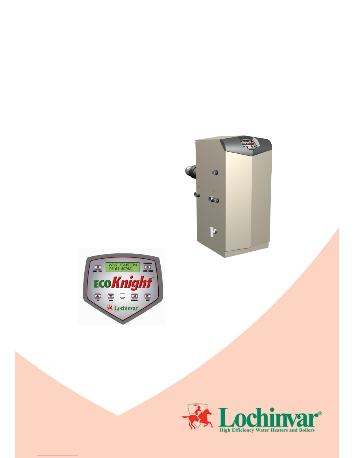
The EcoKnight™ range
High Efficiency Gas Fired Condensing Water Heaters
User & SMART SYSTEM Control Guide
Models:
EKW45CE
EKW60CE
EKW85CE
EKW115CE
EKW145CE
EKW175CE
EKW205CE
EKW235CE
INS0012 Issue No 5 | August 2011
Page 2

2
1.0 USER GUIDE ............................................................................................................................................................................................................................................ 3
1.1 GENERAL REQUIREMENTS ........................................................................................................................................................................................................... 3
1.2 PROCEDURE FOR LIGHTING ........................................................................................................................................................................................................ 3
1.3 PROCEDURE FOR SHUTTING DOWN .......................................................................................................................................................................................... 3
1.4 TEMPERATURE ADJUSTMENT PROCEDURE ............................................................................................................................................................................. 3
1.5 MAINTENANCE ................................................................................................................................................................................................................................ 3
1.6 FROST PROTECTION ..................................................................................................................................................................................................................... 4
1.7 AIR SUPPLY ..................................................................................................................................................................................................................................... 4
1.8 CONDENSATE DRAIN ..................................................................................................................................................................................................................... 4
2.0 SMART SYSTEM CONTROL .................................................................................................................................................................................................................. 5
2.1 GENERAL ......................................................................................................................................................................................................................................... 5
2.2 SMART SYSTEM CONTROL PANEL .............................................................................................................................................................................................. 5
2.3 SEQUENCE OF OPERATION ......................................................................................................................................................................................................... 6
2.4 STATUS DISPLAY SCREENS ......................................................................................................................................................................................................... 7
3.0 USER SETTINGS ..................................................................................................................................................................................................................................... 9
3.1 GENERAL ......................................................................................................................................................................................................................................... 9
3.2 ENTERING THE USER CODE......................................................................................................................................................................................................... 9
3.3 MENU SET A: GENERAL SETTINGS ............................................................................................................................................................................................. 9
3.3.1 WATER HEATER MODEL ................................................................................................................................................................................................ 9
3.3.2 USER CODE ...................................................................................................................................................................................................................... 9
3.3.3 TIME & DATE .................................................................................................................................................................................................................. 10
3.3.4 SOFTWARE VERSION ................................................................................................................................................................................................... 10
3.3.5 TEMPERATURE UNITS .................................................................................................................................................................................................. 10
3.3.6 NIGHT SETBACK TEMPERATURE ............................................................................................................................................................................... 10
3.3.7 NIGHT SETBACK TIME .................................................................................................................................................................................................. 10
3.4 MENU SET C: DATA LOGGING .................................................................................................................................................................................................... 11
3.4.1 TOTAL HRS. RUN ........................................................................................................................................................................................................... 11
3.4.2 IGNITION ATTEMPTS .................................................................................................................................................................................................... 11
3.4.3 LAST 10 ERRORS .......................................................................................................................................................................................................... 11
3.5 EXITING USER SETTINGS MODE ............................................................................................................................................................................................... 11
Page 3

3
1.0 USER GUIDE
1.1 GENERAL REQUIREMENTS
This equipment must be installed by a competent person, registered with a H.S.E. approved
body. All installations must conform to the relevant Gas Safety and Building regulations. Health
& safety requirements must also be taken into account when installing any equipment.
A competent person must also undertake any alterations that require the gas train or flue system
to be broken.
Any interference with a sealed component is forbidden.
Failure to comply with the above may lead to prosecution.
Incorrect use may result in injury and will also invalidate the warranty
1.2 PROCEDURE FOR LIGHTING
1. Ensure that the gas inlet appliance isolating valve is in the “off” position.
2. Press the power rocker switch, positioned on the back of the appliance to bring the equipment on.
3. Press the Enter/Reset button on the Smart System control panel to initiate the burner.
4. The combustion fan should ramp up to full speed to purge the combustion chamber and then drop back
to half rate in order to light. As the gas inlet appliance isolating valve is closed, the controls should go to
a flame failure condition after four ignition attempts (EKW45CE – EKW115CE) or one ignition attempt
(EKW145CE – EKW235CE). If the above occurs correctly, open the gas inlet appliance isolating valve
and reset the unit by depressing the Enter/Reset button on the control panel.
5. The combustion fan will repeat the pre-purge procedure and attempt to light. Once a flame is
established, the LCD display will change to display the rate at which it is firing.
1.3 PROCEDURE FOR SHUTTING DOWN
To take the appliance out of service, the Enter/Reset button should be pressed. If the appliance in to be shut
down for a long period of time, the power supply should be isolated using the rocker switch on the back and the
gas supply should be isolated at the gas inlet appliance isolating valve.
1.4 TEMPERATURE ADJUSTMENT PROCEDURE
The setpoint can be adjusted using the Up and Down buttons on the Smart System control panel. Once the
desired setpoint is displayed, the Enter/Reset button should be pressed to store the value.
The setpoint should be adjusted to ensure that the water is stored at 60°C and distributed at 50°C within 1 (one)
minute at all outlets. Care is needed to avoid much higher temperatures because of the risk of scalding. At 50°C
the risk of scalding is small for most people, but the risk increases rapidly with higher temperatures and for longer
exposure times. The risk to young children and to those with a sensory or mobility loss will be greater. Where a
significant scalding risk has been identified, the use of thermostatic mixing valves on baths and showers should be
considered to reduce temperature, these need to be placed as close to the point of use as possible.
1.5 MAINTENANCE
The SMART SYSTEM control has a built in timer that counts the time period, operating hours and burner initiation
cycles since the unit was last maintained. Once one of these preset values has been exceeded, the display will
show SERVICE DUE every 5 seconds. At this point, it is strongly recommended that a competent person,
preferably appointed by Lochinvar Limited, carries out the necessary maintenance work.
Details of the necessary maintenance work can be found in the Installation, Commissioning and Maintenance
Instructions.
Page 4

4
1.6 FROST PROTECTION
If the temperature of the water at the inlet side of the heat exchanger drops below 7C, the primary pump will be
energised. If the temperature of the water at the inlet side of the heat exchanger drops further and reaches 3C
the burner will fire. If the temperature rises above 10C the burner and the pump will shut down.
1.7 AIR SUPPLY
When installed as a conventionally flued appliance, the room in which the appliance is installed must be
ventilated.
Blocking these air vents may lead to severe injury, serious property damage or death.
The area in which the appliance is installed should not be used to store any other materials.
1.8 CONDENSATE DRAIN
The condensate drain must not be blocked or modified in any way. If fitted with a neutralisation kit, this must be
replaced at least every 12 months to ensure correct operation. Due to its design, no further maintenance should
be necessary.
Page 5

5
2.0 SMART SYSTEM CONTROL
2.1 GENERAL
The Lochinvar EcoKnight™ uses the SMART SYSTEM control interface. The control panel display gives
information on set-up, system status and diagnostic data in words rather than codes.
2.2 SMART SYSTEM CONTROL PANEL
Page 6

6
2.3 SEQUENCE OF OPERATION
OPERATION
DISPLAY
1. Upon a call for heat, the control turns on the appropriate
pumps.
WHR: Standby
OUT: 61.4C (65)
2. The control connects 230 VAC to the fan. The fan does
not run at this time.
If the unit is equipped with a flow switch or low
water cut-off, it must close before the control
powers up the fan.
If the unit is equipped with a manual reset high
limit it must be closed before the control powers
up the fan.
If the unit is equipped with a solenoid valve and/or
a vent valve, they will be energized along with the
fan.
If the unit is equipped with a gas pressure switch,
it must close at this time.
If there is an auxiliary device connected to the
unit, the unit will then provide 24 VAC to its enable
relay. If the auxiliary device has a proving switch,
it must close before the sequence continues.
WHR: Standby
OUT: 61.4C (65)
3. The control then starts a 10 second prepurge cycle.
WHR: PREPURGE
OUT: 61.5C (65)
4. Once the prepurge cycle is complete, and the blocked
drain and auto-reset high limit are closed, the control
starts the 5-second trial for ignition by sending spark
voltage to the spark electrode and opening the gas
valve.
WHR: IGNITION
OUT: 61.5C (65)
5. If the control does not detect flame by the end of the
trial for ignition, the control performs a 10 second
postpurge. On the EKW45CE to EKW115CE models,
the control will perform another prepurge and will try to
light the burner again. If the burner does not light after
4 trials, the control will lockout for 1 hour and then try
another set of 4 trials. On the EKW145CE to
EKW235CE models the unit will lockout until manually
reset.
WHR: POSTPURGE, PREPURGE
OUT: 61.5C (65)
6. If the control detects a flame before the trial for ignition
ends, it begins to modulate the burner in order to
maintain the set point.
WHR: RUN 20% RATE
OUT: 62.6C (65)
7. Once the call for heat is satisfied, the control will turn off
the burner. The fan will remain on for the 10-second
postpurge cycle. The primary pump will continue to run
for its respective pump delay time, and then turn off.
WHR: POSTPURGE
OUT: 64.5C (65))
8. Primary pump off.
WHR: Standby
OUT: 64.8C (65)
Page 7

7
2.4 STATUS DISPLAY SCREENS
Status Display Screens
By using the Previous/Next (◄, ►) arrow keys on the SMART SYSTEM display panel, you can navigate through the six (6)
display screens. Each screen will contain two (2) viewable items. The following is a description of the individual items an d
what they can display:
Screen
Display shows:
Description
1
WHR: OFF
The unit has been turned OFF by the Enter/Reset button on the SMART
SYSTEM display panel.
STANDBY
The unit has not received a call for heat from a tank thermostat nor has
it received a call for heat from a tank sensor.
SET POINT MET
The unit has met the water temperature set point, but is still receiving a
call for heat from either a tank sensor or a tank thermostat.
PREPURGE
The unit has initiated a 10 second purge period on a call for heat.
IGNITION
The unit has begun a 5 second spark period to ignite the main burner.
RUN***% RATE
The unit has fired and is running at the displayed percentage.
POSTPURGE
The call for heat has been satisfied and the unit runs the fan for an
additional 10 seconds to clear the combustion chamber and vent system
of residual flue products.
SERVICE
The unit has been placed in a temporary mode that will allow the unit to
fire at 100% of rate for the purpose of combustion analysis.
OUT:***.*C
The outlet temperature is displayed.
OPEN
The control does not detect the outlet sensor.
SHORTED
The outlet sensor wires or the sensor itself has become shorted.
Press the Next ► arrow key on the SMART SYSTEM display to access Screen 2
2
IN: ***.*C
If a tank sensor is installed, only the inlet temperature will be displayed.
***.*C (***)
When a tank thermostat is installed, the control will display the inlet
temperature as well as the set point in brackets.
OPEN
The control does not detect the inlet sensor
SHORTED
The inlet sensor wires or the sensor itself has become shorted.
RISE: ***.*C
The difference between the inlet temperature and the outlet
temperature.
Press the Next ► arrow key on the SMART SYSTEM display to access Screen 3.
3
FLUE: ***.*C
The control will display the flue temperature.
OPEN
The control does not detect the flue sensor.
SHORTED
The flue sensor wires or the sensor itself has become grounded.
TANK: ***.*C (***)
The control will display the tank temperature; if used, the set point
appears in brackets.
OPEN
The control does not detect the tank sensor.
SHORTED
The tank sensor wires or the sensor itself has become shorted.
Press the Next ► arrow key on the SMART SYSTEM display to access Screen 4.
4
FAN SPD: ****RPM
The control will display the actual fan motor RPM.
FLAME SIG: **.*UA
The control will display the flame signal in dc micro amps.
Page 8

8
Press the Next ► arrow key on the SMART SYSTEM display to access Screen 5.
5
WHR CFH: OFF
The control has not received a call for heat from a tank thermostat or
tank sensor.
ON
The control has received a call for heat from a tank thermostat or tank
sensor.
WHR PUMP: OFF
The control has not received a DHW call for heat and has not powered
the primary pump.
ON
The control has received a DHW call for heat and has powered the
primary pump.
DELAY
The DHW call for heat has been satisfied and the primary pump is
running for a fixed time to remove any residual heat.
Press the Next ► arrow key on the SMART SYSTEM display to access Screen 6.
6
NOT USED: N/A
Not used.
0-10V IN: **.VDC
The control will display a 0-10Vdc signal received from a Building
Management System (BMS) connected to the unit.
Press the Next ► arrow key on the SMART SYSTEM display to access Screen 7.
7
Cas: Off
The Master control has been turned off by the Enter/Reset button on the
Smart System display.
Cas: Standby
The Master water heater has not received a call for heat from a remote
thermostat.
Cas: 61.4C (65)
The Cascade is now active. The system temperature will be displayed.
The Cascade set point will be displayed in brackets.
Cas: Setpoint Met
The Cascade has met the water temperature set point, but is still
receiving a call for heat from a tank sensor.
Cas: No Members
The Master control could not detect any Member controls to participate
in the Cascade.
PMP: Off
The Master control has not received a call for heat from a tank sensor
and has not powered the primary pump.
PMP: On
The Master control has received a call for heat from a remote thermostat
and has powered the system pump.
PMP: Delay
The tank call for heat has been satisfied and the tank pump is running for
a fixed time to remove any residual heat.
Press the Next ► arrow key on the SMART SYSTEM display to access Screen 8.
8
Cas Pow: ***% ***%
The first percentage shows the firing rate that is being sent to the last
water heater called on. The second percentage shows the total power
available to the Cascade.
Present: 01234567
Example:
Present: 23----01
Shows the number of water heaters connected to the Cascade. The
Master is designated as 0. Members will be designated 1 - 7. If a “-“ is
used in place of a number, that water heater is either not connected, or
in a lockout mode and not available for the Cascade. If the number is
flashing, then that water heater is providing heat to the Cascade. As the
lead water heater is changed from day to day, that water heater’s
address will be shown first in the string of numbers. In the example,
water heaters 0 - 3 are present and water heater 2 is the lead water
heater.
Press the Next ► arrow key on the SMART SYSTEM display to roll back to Screen 1. At any point if you wish to
access an earlier screen, press the Previous ◄ arrow key on the SMART SYSTEM display.
Page 9

9
3.0 USER SETTINGS
3.1 GENERAL
Certain functions within the boiler are changeable by the user but are password protected to prevent accidental
modification. What follows is a guide showing how to access the functions and modify them.
3.2 ENTERING THE USER CODE
To access the user control the following procedure should be followed:
1. If the heater is operating, press the Enter/Reset button to turn the unit off.
2. Press and hold the Menu/Exit button for 5 seconds. At this point the display will change to show:
Enter Menu Code:
0000
3. Press the UP button 4 times. The display should now show:
Enter Menu Code:
0004
4. Press the Previous button 2 times. The display should now show:
Enter Menu Code:
0004
5. Press the Up button 7 times. The display should now show:
Enter Menu Code:
0704
6. Press the Enter/Reset button. The display should now show:
Enter Menu Code:
USER CODE
3.3 MENU SET A: GENERAL SETTINGS
After 2 seconds the screen will show:
>A General
B N/A
Pressing the Enter/Reset button will access the General menu set. From here, the following sub-sections can be
accessed by moving the caret symbol “>” to the appropriate line using the Up or Down buttons and then pressing
the Enter/Reset button.
3.3.1 WATER HEATER MODEL
This is a display only parameter that will display the model name of the unit.
3.3.2 USER CODE
This setting can be used to modify the user access code. This is done using the Up, Down, Previous and Next
buttons. Once the desired code has been set, the Enter/Reset button should be pressed to save the setting.
NOTE: If this setting is modified, please make a note of the new code as it can only be reset using the computer
interface.
Page 10

10
3.3.3 TIME & DATE
The control uses an internal clock for the night setback feature and for logging of events. For these features to
work correctly, the clock must be set when the water heater is first installed or anytime the water heater has been
powered off for more than 30 days.
The date and time are displayed as “YY:MM:DD W hh:mm”.
YY = year
MM = month
DD = date
W = day (1 = Sunday, 2 = Monday, etc.)
hh = hour (24 hour time; 2:00 PM = 14:00)
mm = minutes.
The date and time are set using the Up, Down, Previous and Next buttons. Once set, the Enter/Reset button
should be pressed to save the setting.
NOTE: The clock does not automatically adjust for Daylight Saving Times and therefore will require a manual
adjustment.
3.3.4 SOFTWARE VERSION
This is a display only parameter that will display the version number of the software loaded into the unit.
3.3.5 TEMPERATURE UNITS
The control can be configured to display the temperature units in C of F. The default setting is C, to change
this, the Up or Down button should be used and the Enter/Reset button pressed to store the desired setting.
3.3.6 NIGHT SETBACK TEMPERATURE
Once the internal clock has been set correctly, the night setback feature can be used to program a lower water
temperature set point for water heating. This feature is only used when a tank sensor is used. The temperature
range for this parameter is 0C to 60c. The feature is turned off with a setting of 0C. The default value is 0C.
To modify the temperature setting, the Up or Down button should be used and the Enter/Reset button pressed to
store the desired setting.
3.3.7 NIGHT SETBACK TIME
If the Night Setback Temperature is set to anything other than 0C, the night setback feature becomes active.
This will require start and stop times to be programmed for the days that reduced temperatures are required.
Each day of the week (Sunday through Saturday) will have an on and off time. Using the Previous and Next
buttons the desired time slot (e.g. Monday ON, Monday Off, Tuesday On etc.) can be selected. Once the desired
time slot is selected, the Up and Down buttons can be used to set the required time.
Example: Monday ON: 22:30, Tuesday OFF: 6:45. If you wish to skip a day and have no night setback, leave the
on and off times the same. The default times for each day will be 00:00 (midnight).
Page 11

11
3.4 MENU SET C: DATA LOGGING
Pressing the Down arrow followed by the Enter/Reset button will access the Data Logging menu set. This menu
set has three options that will display recorded data about the operation of the water heater. To access the
options, use the Up or Down buttons followed by the Enter/Reset button.
3.4.1 TOTAL HRS. RUN
The Total Hrs. Run option shows the total time that the burner in the water heater has been operating for since the
counter was last reset.
3.4.2 IGNITION ATTEMPTS
The Ignition Attempts option will show the number of times the water heater has attempted to fire since the counter
was last reset.
3.4.3 LAST 10 ERRORS
The Last 10 Errors option will show the date, time and fault description for the last ten errors that caused the boiler
the stop. The Up or Down button should be used to scroll through the errors
3.5 MENU SET E: WHR SETTINGS
Pressing the Down arrow 2 times followed by the Enter/Reset button will access the Water Heater Settings menu
set. This menu set has one option; to access the option press the Enter/Reset button.
3.5.1 TANK SETPOINT
The Tank Setpoint parameter allows the setpoint of the water heater to be adjusted when a flow temperature
sensor is not used. Lochinvar Limited recommends that a flow sensor is always used with this appliance.
The setpoint should be adjusted to ensure that the water is stored at 60°C and distributed at 50°C within 1 (one)
minute at all outlets. Care is needed to avoid much higher temperatures because of the risk of scalding. At 50°C
the risk of scalding is small for most people, but the risk increases rapidly with higher temperatures and for longer
exposure times. The risk to young children and to those with a sensory or mobility loss will be greater. Where a
significant scalding risk has been identified, the use of thermostatic mixing valves on baths and showers should be
considered to reduce temperature, these need to be placed as close to the point of use as possible.
The default value is 60C. To modify the temperature setting, the Up or Down button should be used and the
Enter/Reset button pressed to store the desired setting.
3.6 EXITING USER SETTINGS MODE
To exit the user-setting mode, the Menu/Exit button should be pressed whilst in the Main Menu screen.
Alternatively, if no button is pressed for 60 seconds, the water heater will revert to its normal operating screen.
Once this has occurred, the Enter/Reset button should be pressed to switch the unit on.
Page 12

 Loading...