

Lochinvar ECOKNIGHT EKW46CE, ECOKNIGHT EKW61CE, ECOKNIGHT EKW116CE, ECOKNIGHT EKW206CE, ECOKNIGHT EKW146CE Installation Manual
...Page 1

1
Models
EKW46CE
EKW61CE
EKW86CE
ECOKNIGHT™
FLOOR STANDING GAS FIRED CONDENSING
CIRCULATING TYPE WATER HEATER
Installation, Commissioning, Maintenance
and User instructions
installation manual_ecoknight 46-86_january2018
Page 2

2
Table of Contents
1.0 INTRODUCTION ...................................................................................................................................................................................................................... 4
2.0 SAFETY GUIDELINES............................................................................................................................................................................................................. 5
2.1 GENERAL DESCRIPTION OF SAFETY SYMBOLS USED ................................................................................................................................................ 5
2.2 WHAT TO DO IF YOU SMELL GAS .................................................................................................................................................................................. 6
3.0 PRINCIPAL PARTS ................................................................................................................................................................................................................. 7
4.0 TECHNICAL DATA .................................................................................................................................................................................................................. 9
5.0 DIMENSIONS AND CLEARANCE ......................................................................................................................................................................................... 10
5.1 DIMENSIONAL DRAWINGS ........................................................................................................................................................................................... 10
5.2 CLEARANCES................................................................................................................................................................................................................ 11
6.0 GENERAL REQUIREMENTS ................................................................................................................................................................................................. 12
6.1 RELATED DOCUMENTS ................................................................................................................................................................................................ 12
7.0 WATER QUALITY ................................................................................................................................................................................................................. 13
7.1 WATER QUALITY /HARD WATER .................................................................................................................................................................................. 13
8.0 LOCATION ............................................................................................................................................................................................................................ 13
8.1 PLANT ROOM REQUIREMENTS .................................................................................................................................................................................... 13
8.2 GENERAL REQUIREMENTS .......................................................................................................................................................................................... 13
8.3 CLEARANCES................................................................................................................................................................................................................ 13
8.4 CONDENSATE DRAIN ................................................................................................................................................................................................... 14
9.0 GAS SUPPLY ........................................................................................................................................................................................................................ 14
9.1 SERVICE PIPES ............................................................................................................................................................................................................. 14
9.2 METERS ........................................................................................................................................................................................................................ 14
9.3 GAS SUPPLY PIPES ...................................................................................................................................................................................................... 14
9.4 BOOSTED SUPPLIES .................................................................................................................................................................................................... 14
9.5 PLANT-ROOM CONTROL VALVE .................................................................................................................................................................................. 14
9.6 EQUIPMENT GAS SYSTEM LEAK CHECK ..................................................................................................................................................................... 14
10.0 FLUE SYSTEM ...................................................................................................................................................................................................................... 15
10.1 FLUE SYSTEM GENERAL REQUIREMENTS ................................................................................................................................................................. 15
10.2 FLUE SYSTEM TECHNICAL DETAILS AND MAXIMUM FLUE LENGTH ......................................................................................................................... 16
10.3 FLUE DISCHARGE ......................................................................................................................................................................................................... 16
10.4 CONDENSATE DRAIN ................................................................................................................................................................................................... 16
10.5 APPROVED FLUE SYSTEM ........................................................................................................................................................................................... 18
10.6 INSTALLATION PRECAUTIONS ..................................................................................................................................................................................... 18
10.7 ROOM SEALED (TYPE C) FLUE ASSEMBLY ................................................................................................................................................................. 19
10.8 INSTALLATION OF FLUE TRANSITION KIT TO EKW46CE – EKW61CE WATER HEATERS .......................................................................................... 19
10.9 INSTALLATION OF TRANSITION KIT TO EKW86CE WATER HEATERS ....................................................................................................................... 21
10.10 C13 CONCENTRIC HORIZONTAL FLUE SYSTEMS ................................................................................................................................................ 23
10.11 HORIZONTAL FLUE TERMINAL INSTALLATION .................................................................................................................................................... 24
10.12 FLUE TERMINAL GUARDING ................................................................................................................................................................................. 24
10.13 C33 CONCENTRIC VERTICAL FLUE SYSTEMS ..................................................................................................................................................... 25
10.14 VERTICAL FLUE TERMINAL INSTALLATION .......................................................................................................................................................... 26
10.15 TYPE C
43
(U DUCT) ................................................................................................................................................................................................. 31
10.16 C
53
(TWIN PIPE) FLUE SYSTEMS ........................................................................................................................................................................... 31
10.17 TYPE B23 (CONVENTIONAL FLUE WITH FAN ASSISTANCE) ................................................................................................................................. 36
10.18 C63 Certified Flue Systems ...................................................................................................................................................................................... 37
11.0 AIR SUPPLY ......................................................................................................................................................................................................................... 38
11.1 COMBUSTION VENTILATION ........................................................................................................................................................................................ 38
11.2 COOLING VENTILATION................................................................................................................................................................................................ 38
12.0 WATER CONNECTIONS ....................................................................................................................................................................................................... 39
12.1 GENERAL ...................................................................................................................................................................................................................... 39
12.2 OPEN VENTED SYSTEM ARRANGEMENT .................................................................................................................................................................... 40
12.3 UN-VENTED SYSTEM ARRANGEMENT ........................................................................................................................................................................ 40
12.4 CIRCULATING PUMPS .................................................................................................................................................................................................. 41
12.5 PRIMARY PIPEWORK HEADER SIZING ........................................................................................................................................................................ 42
13.0 CONTROL OPTIONS/INSTALLATION ................................................................................................................................................................................... 42
13.1 VESSEL TEMPERATURE SENSOR SINGLE WATER HEATER INSTALLATION ............................................................................................................ 43
1.1 VESSEL TEMPERATURE SENSOR MULTIPLE WATER HEATER INSTALLATION ........................................................................................................ 43
13.2 SENSOR WIRING........................................................................................................................................................................................................... 43
14.0 SCHEMATICS ....................................................................................................................................................................................................................... 44
1.1 KEY FOR SCHEMATICS ................................................................................................................................................................................................ 44
14.1 STANDALONE INSTALLATION, SINGLE WATER HEATER ............................................................................................................................................ 45
1.1 BMS INSTALLATION, SINGLE WATER HEATER............................................................................................................................................................ 46
14.2 INSTALLATION, TWO WATER HEATERS WITH SINGLE VESSEL – ALTERNATE LEAD WITH STRAP-ON SENSOR .................................................. 47
14.3 MULTIPLE WATER HEATERS WITH SINGLE VESSEL .................................................................................................................................................. 48
14.4 MULTIPLE WATER HEATERS WITH MULTIPLE LST DIRECT STORAGE VESSELS ..................................................................................................... 49
15.0 ELECTRICAL SUPPLY.......................................................................................................................................................................................................... 50
15.2 EXTERNAL CONTROLS ................................................................................................................................................................................................. 50
15.3 HIGH VOLTAGE CONNECTOR STRIP ........................................................................................................................................................................... 52
15.4 LOW VOLTAGE CONNECTOR STRIP ............................................................................................................................................................................ 52
15.5 ELECTRICAL CONNECTIONS ....................................................................................................................................................................................... 54
15.6 FUSES ........................................................................................................................................................................................................................... 54
15.7 ARC WELDING PRECAUTIONS ..................................................................................................................................................................................... 54
15.8 WIRING DIAGRAM ......................................................................................................................................................................................................... 55
15.9 LADDER DIAGRAM ........................................................................................................................................................................................................ 56
16.0 SMART SYSTEM CONTROL ................................................................................................................................................................................................. 57
16.1 GENERAL ...................................................................................................................................................................................................................... 57
16.2 SMART SYSTEM CONTROL PANEL .............................................................................................................................................................................. 57
16.3 ACCESS MODES ........................................................................................................................................................................................................... 57
16.4 SAVING PARAMETERS ................................................................................................................................................................................................. 58
16.5 STATUS DISPLAY SCREENS ........................................................................................................................................................................................ 60
17.0 COMMISSIONING AND TESTING ......................................................................................................................................................................................... 62
17.1 ELECTRICAL INSTALLATION ........................................................................................................................................................................................ 62
17.2 GAS INSTALLATION ...................................................................................................................................................................................................... 62
17.3 WATER CONNECTIONS ................................................................................................................................................................................................ 62
Page 3

3
17.4 COMMISSIONING THE EQUIPMENT ............................................................................................................................................................................. 62
17.5 TEMPERATURE ADJUSTMENT PROCEDURE .............................................................................................................................................................. 63
17.6 LEGIONELLA PREVENTION .......................................................................................................................................................................................... 63
17.7 PASTEURISATION ......................................................................................................................................................................................................... 64
17.8 PASTEURISATION USING THE NIGHT SET BACK FACILITY ........................................................................................................................................ 64
17.9 INSTALLATION NOISE ................................................................................................................................................................................................... 64
18.0 LPG FUEL ............................................................................................................................................................................................................................. 64
18.1 RELATED DOCUMENTS ................................................................................................................................................................................................ 64
18.2 CONVERSION TO LPG .................................................................................................................................................................................................. 65
18.3 LPG COMMISSIONING AND TESTING........................................................................................................................................................................... 66
19.0 MAINTENANCE..................................................................................................................................................................................................................... 67
19.1 GENERAL ...................................................................................................................................................................................................................... 67
19.2 MAINTENANCE SCHEDULE .......................................................................................................................................................................................... 67
19.3 BURNER INSPECTION .................................................................................................................................................................................................. 67
19.4 BURNER REMOVAL....................................................................................................................................................................................................... 68
19.5 CLEANING THE HEAT EXCHANGER ............................................................................................................................................................................. 68
19.6 DRAINING WATER HEATER SYSTEM ........................................................................................................................................................................... 68
19.7 REFILLING THE SYSTEM .............................................................................................................................................................................................. 69
19.8 OTHER CHECKS............................................................................................................................................................................................................ 69
20.0 SMART SYSTEM CONTROL SETTINGS ............................................................................................................................................................................... 70
20.1 DISPLAY PANEL ACCESS MENU .................................................................................................................................................................................. 70
20.2 PARAMETER SETTING .................................................................................................................................................................................................. 71
21.0 VIEWABLE AND CHANGEABLE CONTROL PARAMETERS ................................................................................................................................................ 74
21.1 GENERAL ...................................................................................................................................................................................................................... 74
21.2 DATA LOGGING ............................................................................................................................................................................................................. 75
21.3 FUNCTIONS ................................................................................................................................................................................................................... 75
21.4 DHW SETTINGS............................................................................................................................................................................................................. 75
21.5 ANTI-CYCLING............................................................................................................................................................................................................... 76
21.6 CONTROL MODES......................................................................................................................................................................................................... 76
21.7 BUILDING MANAGEMENT SYSTEM (BMS).................................................................................................................................................................... 78
21.8 CIRCULATION PUMPS .................................................................................................................................................................................................. 79
21.9 SERVICE NOTIFICATION ............................................................................................................................................................................................... 80
21.10 BASIC SETUP ......................................................................................................................................................................................................... 81
22.0 ErP DATA TABLE ................................................................................................................................................................................................................. 81
23.0 USER INSTRUCTIONS .......................................................................................................................................................................................................... 82
23.1 GENERAL REQUIREMENTS .......................................................................................................................................................................................... 82
23.2 PROCEDURE FOR LIGHTING ........................................................................................................................................................................................ 82
23.3 PROCEDURE FOR SHUTTING DOWN........................................................................................................................................................................... 82
23.4 SMART SYSTEM CONTROL .......................................................................................................................................................................................... 83
23.5 TEMPERATURE ADJUSTMENT PROCEDURE .............................................................................................................................................................. 83
23.6 MAINTENANCE .............................................................................................................................................................................................................. 84
23.7 AIR SUPPLY................................................................................................................................................................................................................... 84
23.8 SMART SYSTEM CONTROL .......................................................................................................................................................................................... 84
23.9 PARAMETER SETTINGS ............................................................................................................................................................................................... 84
Page 4

4
1.0 INTRODUCTION
The Lochinvar EcoKnight™ range is a floor standing direct gas fired circulating type condensing water heater.
The equipment comprises of stainless steel radial burner assembly and heat exchanger that permits fully
condensing operation. EcoKnight™ water heaters must be used in conjunction with an appropriately sized
LST direct storage vessel (available from Lochinvar Limited as an ancillary option)
The burner is initiated by a full electronic ignition sequence control that incorporates a spark ignition and a
flame rectification device for supervision of the flame.
The output from the water heater is regulated by a variable speed combustion fan and gas/air ratio controls to
maintain the correct combustion at all levels of modulation. This configuration allows modulation down to 20%
of the rated output.
For the correct operation of the water heater, it is essential that a suitably sized pump is utilised to maintain a
constant water flow rate through the heat exchanger. A suitable shunt pump is supplied as an ancillary with
the water heater.
This equipment is intended for use on Group H Natural Gas (2
nd
Family) and LPG propane (3rd Family). The
information relating to propane firing is to be found in Section 18.0 LPG FUEL.
This equipment MUST NOT use gas other than that for which it has been designed and
adjusted.
This equipment must be installed by a competent person, registered with a H.S.E. approved body. All
installations must conform to the relevant Gas Safety and Building Regulations. Health & Safety requirements
must also be taken into account when installing any equipment. Failure to comply with the above may lead to
prosecution.
If the equipment is to be connected to an unvented (pressurised) system, care must be taken to ensure all
extra safety requirements are satisfied should a high or low-pressure condition occur in the system.
The equipment is designed for direct connection to a flue system.
Ancillary Options:
Primary Circulating Pump (EKW46CE & EKW61CE) LM900151A
Primary Circulating Pump (EKW86CE) LM900141A
LST Direct Storage Vessel (From 297 litre to 2820 litre) See www.lochinvar.ltd.uk
Unvented/Boosted Water System Kits See www.lochinvar.ltd.uk
De-stratification Pump Kit WH9
Condensate Neutralisation Kit KIT2000
Flue System Components See Section 10.0
Page 5

5
2.0 SAFETY GUIDELINES
READ AND UNDERSTAND THE INSTRUCTIONS
Read and fully understand all instructions before attempting to operate maintain or install the
unit.
Keep these instructions near the water heater for quick reference.
This equipment must be installed by a competent person, registered with the H.S.E. approved body. All installations
must conform to the relevant Gas Safety and Building Regulations. Health & Safety requirements must also be
taken into account when installing any equipment. Failure to comply with the above may lead to prosecution
Without written approval of the manufacturer the internals of the water heater may not be changed. When changes are
executed without approval, the water heater certification becomes invalid.
Commissioning, maintenance and repair must be done by a skilled installer/engineer, according to all applicable
standards and regulations.
2.1 GENERAL DESCRIPTION OF SAFETY SYMBOLS USED
BANNED
A black symbol inside a red circle with a red diagonal indicates an action that should not be
performed
WARNING
A black symbol added to a yellow triangle with black edges indicates danger
ACTION REQUIRED
A white symbol inserted in a blue circle indicates an action that must be taken to avoid risk
ELECTRICAL HAZARD
Observe all signs placed next to the pictogram. the symbol indicates components of the unit and
actions described in this manual that could create an electrical hazard.
HOT SURFACES
The symbol indicates those components with a high surface temperature that could create a risk.
This symbol shows essential information which is not safety related
Recover or recycle material
Page 6

6
2.2 WHAT TO DO IF YOU SMELL GAS
Warning if you smell gas
No naked flames, no smoking!
Avoid causing sparks, do not switch on or off electrical equipment or lights
Open windows and doors
Shut off the main gas supply
Warn occupants and leave the building
After leaving the building alert the local gas supply company
Do not re-enter the building until it is safe to do so
Lochinvar Limited is not liable for any damage caused by inaccurately following these
installation instructions. Only original parts may be used when carrying out any repair or
service work.
This appliance is not intended for use by persons (including children) with reduced physical,
sensory or mental capabilities, or lack of experience and knowledge, unless they have been
given supervision or instruction concerning use of the appliance by a person responsible
for their safety. Children MUST be supervised to ensure that they do not play with the
appliance.
Page 7

7
3.0 PRINCIPAL PARTS
ITEM
DESCRIPTION
FUNCTION
NOTE
Stainless steel heat
exchanger
Allows water to flow through specially designed coils for maximum heat transfer, while providing
protection against flue gas corrosion. The coils are encased in a jacket that contains the combustion
process.
Not Shown
in 3.1.2
2
Heat exchanger access
cover
Allows access to the combustion side of the heat exchanger coils.
Not Shown
in 3.1.2
3
Fan
The fan pulls in air and gas through the venturi (item 5). Air and gas mix inside the fan and are
pushed into the burner, where they burn inside the combustion chamber.
Not Shown
in 3.1.2
4
Gas valve
The gas valve senses the negative pressure created by the fan, allowing gas to flow only if the gas
valve is powered and combustion air is flowing.
Not Shown
in 3.1.2
5
Venturi
The venturi controls air and gas flow into the burner.
Not Shown
in 3.1.2
6
Flue gas sensor
This sensor monitors the flue gas exit temperature. The control module will modulate and shut down
the boiler if the flue gas temperature gets too hot. This protects the flue pipe from overheating.
7
Boiler outlet temperature
sensor
This sensor monitors boiler outlet water temperature.
Not Shown
in 3.1.2
8
Boiler inlet temperature
sensor
This sensor monitors return water temperature.
Not Shown
in 3.1.2
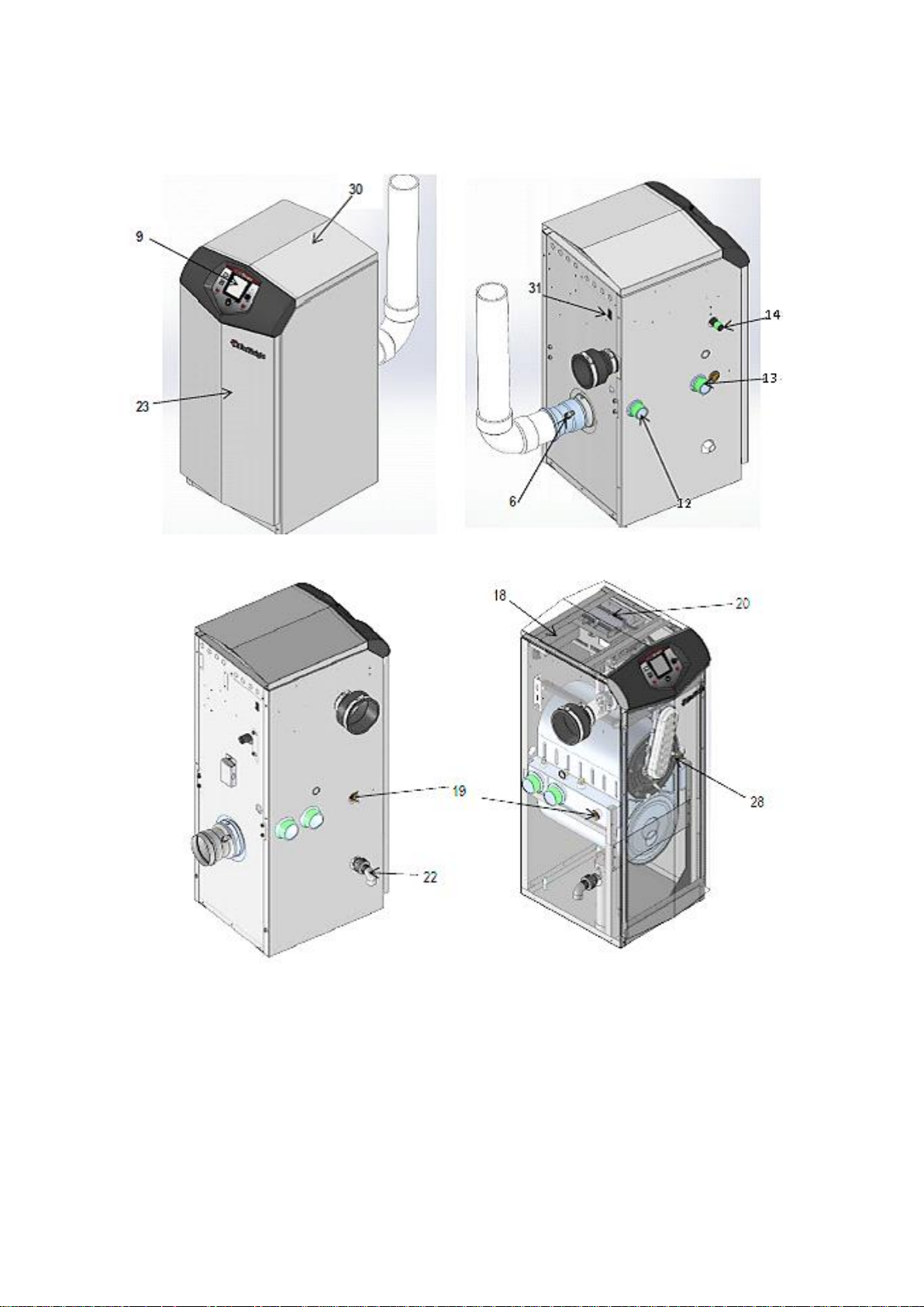
9
Electronic display
The electronic display consists of 7 buttons and a dual line 32-character liquid crystal display.
10
Flue pipe adapter
Allows for the connection of the flue system to the boiler.
Not Shown
in 3.1.2
11
Burner
Made with metal fibre and stainless steel construction, the burner uses pre-mixed air and gas and
provides a wide range of firing rates.
12
Water outlet
BSP water connection that supplies hot water to the system, either 1-1/4" or 2", depending on the
model.
13
Water inlet
BSP water connection that returns water from the system to the heat exchanger, either 1-1/4" or 2",
depending on the model.
14
Gas connection pipe
Threaded pipe connection, 1/2 “, 3/4", or 1", depending on the model. This pipe should be connected
to the incoming gas supply for the purpose of delivering gas to the boiler.
15
SMART Control Module
The SMART Control responds to internal and external signals and controls the fan, gas valve, and
pumps to meet the demand.
Not Shown
in 3.1.2
16
Manual air vent
Designed to remove trapped air from the heat exchanger coils.
Not Shown
in 3.1.2
17
Air intake adapter
Allows for the connection of the air intake pipe to the boiler.
Not Shown
in 3.1.2
18
Mains voltage junction box
The junction box contains the connection points for the mains voltage power and all pumps.
19
Boiler drain port
Location from which the heat exchanger can be drained.
20
Low voltage connection
board
The connection board is used to connect external low voltage devices.
21
Low voltage wiring
connections (knockouts)
Conduit connection points for the low voltage connection board.
Not Shown
in 3.1.2
22
Condensate drain
connection
Connects the condensate drain line to a 1/2" PVC union.
23
Access cover - front
Provides access to the gas train and the heat exchanger.
24
Ignition electrode
Provides direct spark for igniting the burner.
Not Shown
in 3.1.2
25
Flame inspection window
The quartz glass window provides a view of the burner surface and flame.
Not Shown
in 3.1.2
26
Gas shutoff valve
Manual valve used to isolate the gas valve from the gas supply.
Not Shown
in 3.1.2
27
High limit sensor
Device that monitors the outlet water temperature. If the temperature exceeds its setting, it will break
the control circuit, shutting the boiler down.
Not Shown
in 3.1.2
28
Flame sense electrode
Used by the control module to detect the presence of burner flame.
29
Mains voltage wiring
connections (knockouts)
Conduit connection points for the mains voltage junction box
Not Shown
in 3.1.2
30
Top panel
Removable panel to gain access to the internal components.
31
Power switch
Turns 230 VAC ON/OFF to the boiler.
32
Levelling legs
Used to allow the heat exchanger to be levelled. This is needed for the proper draining of the
condensate from the combustion chamber
Not Shown
in 3.1.2
3.1.1 PRINCIPLE PARTS LIST TO BE USED IN CONJUNCTION WITH 3.1.2
Page 8
8
3.1.2 PRINCIPLE PARTS SHOWN, TO BE USED WITH 3.1.1
FRONT VIEW ALL MODELS
REAR VIEW MODELS EKW46CE-EKW61CE
REAR VIEW MODELS EKW86CE
LEFT SIDE VIEW MODELS EKW86CE
Page 9

9
4.0 TECHNICAL DATA
Model Number
EKW46CE
EKW61CE
EKW86CE
GENERAL DATA
Product I.D. Number CE 0063CQ3351
Classification
II2H3B/P
Input (gross)
kW
44
61.5
83.5
Input (net)
kW
39.6
55.4
75.2
Recovery Rate (44° ΔT)
l/hr
806
1153
1567
Recovery Rate (50° ΔT)
l/hr
709
1014
1379
Heat generator seasonal efficiency
%
96.4
95.6
95.6
Shipping Weight
kg
75
79
102
NOX @0%O2
mg/kWh
39
39
39
GAS DATA – G20
Nominal gas inlet pressure
mbar
20
Maximum gas inlet pressure
mbar
25
Minimum gas inlet pressure
mbar
17.5
Gas flow rate
m3/hr
4.2
5.9
8
Flue gas mass rate (@ 9.0% CO2)
g/sec
16
22.3
30.4
Gas inlet connection size
“ BSP ½ ½
¾
GAS DATA – G31
Nominal gas inlet pressure
mbar
37
Maximum gas inlet pressure
mbar
45
Minimum gas inlet pressure
mbar
27
Gas flow rate – m3/hr
m3/hr
1.7
2.3
3.1
Flue gas mass rate (@ 10.5% CO2)
g/sec
16.7
23.2
31.6
Gas inlet connection size
“ BSP ½ ½
¾
ELECTRICAL DATA
Power consumption
W
120
144
180
Power supply Single phase 230v/50Hz
Protection class
IP00
WATER DATA
Water content
litres
4.9
6.4
9.1
Water connections (F & R)
“ BSP
1 ¼
2
Max. water pressure (PMS)
bar
11
Min. water pressure
bar
0.5
Maximum water temperature
°C
80
Page 10
10
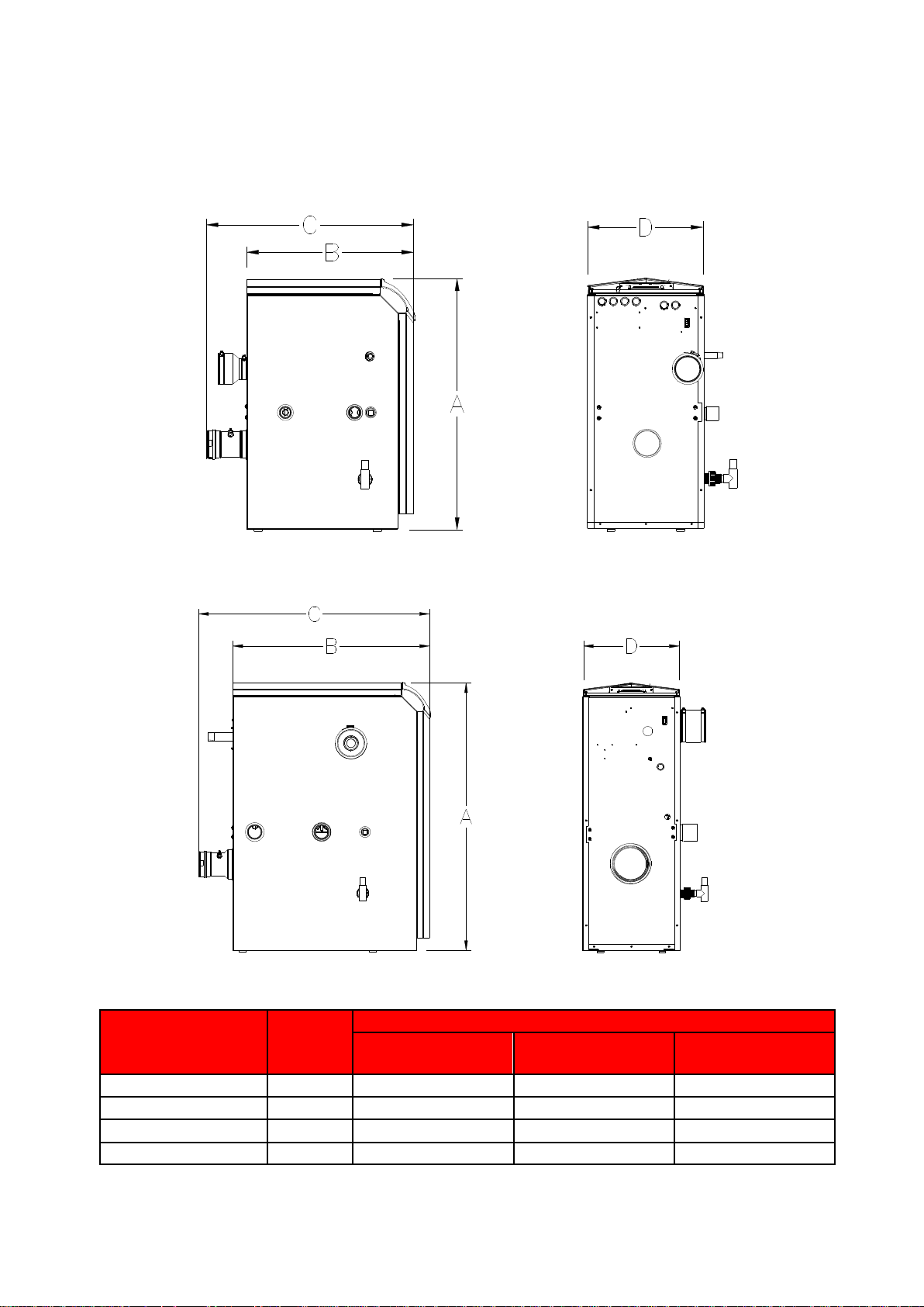
5.0 DIMENSIONS AND CLEARANCE
5.1 DIMENSIONAL DRAWINGS
Note full dimensional drawings showing connection sizes and positions are available from Lochinvar Technical Support
5.1.1 DIMENSIONAL DRAWING EKW46CE-EKW61CE
5.1.2 DIMENSIONAL DRAWING EKW86CE,
Dimension
Unit
Model
EKW46CE
EKW61CE
EKW86CE
A
mm
845
845
1080
B
mm
457
565
502
C
mm
701
701
641
D
mm
394
394
394
Page 11
11
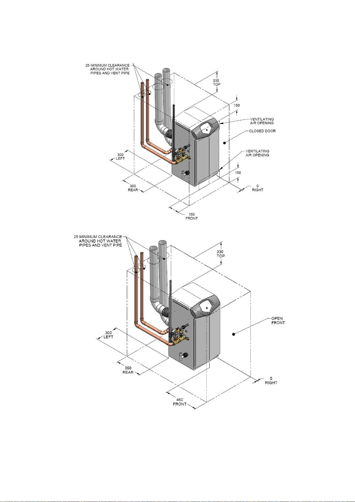
5.2 CLEARANCES
5.2.1 ENCLOSURE INSTALLATION CLEARANCES (MM)
5.2.2 PLANT-ROOM INSTALLATION CLEARANCES (MM)
400
400
Page 12

12
6.0 GENERAL REQUIREMENTS
The Lochinvar EcoKnight™ condensing water heater has been designed to operate trouble free for many years. These instructions
should be followed closely to obtain the maximum usage and efficiency of the equipment.
READ AND UNDERSTAND THE INSTRUCTIONS
Read and fully understand all instructions before attempting to operate maintain or install the unit.
6.1 RELATED DOCUMENTS
It is law that all gas appliances are installed by competent persons, in accordance with The Gas Safety (Installation and Use)
Regulations 1998. Failure to install appliances correctly could lead to prosecution. It is in your own interest, and that o f safety, to
ensure that this law is complied with.
The installation of the equipment MUST be in accordance with the relevant requirements of the Gas Safety Regulations, Building
Regulations, I.E.E. Regulations and the bylaws of the local water undertaking. The installation should also be in accordance with
any relevant requirements of the local gas distributor and local authority.
In addition, the installation should follow the relevant guidance offered in the following documents. It is not practical to list all relevant
information but emphasis is placed on the following documents, as failure to comply with the guidance given will almost certainly
result in an unsatisfactory installation:
Regulation
Description
BS EN 1858: 2008 + A1: 2011
Chimneys, Components. Concrete flue blocks.
BS 5440-1: 2008
Flueing and ventilation for gas appliances of rated input not exceeding 70 kW net (1st, 2nd and 3rd family gases).
Specification for installation of gas appliances to chimneys and for maintenance of chimneys.
BS 5440-2: 2009
Installation and maintenance of flues and ventilation for gas appliances of rated input not exceeding 70 kW net (1st, 2nd
and 3rd family gases). Specification for installation and maintenance of ventilation for gas appliances.
BS 6644: 2011
Specification for Installation of gas-fired hot water Heaters of rated inputs between 70 kW (net) and 1.8 MW (net) (2nd
and 3rd family gases).
BS EN 806 1-5
Specifications for installations inside buildings conveying water for human consumption.
BS 7671 :2008 + A3:2015
Code of practice for low temperature hot water systems of output greater than 45 kW.
BS 7074: 1989 Parts 1 and 2
Application, selection and installation of expansion vessels and ancillary equipment for sealed systems.
BS 7671: 2008 + A1: 2011
Requirements for electrical installations, I.E.E. wiring regulations seventeenth edition.
BS 7671: Amendment 2: August
2013
BS EN 12828:2012+A1:2014
Heating systems in buildings. Design for water-based heating systems.
CP 342 (Part 2 1974):
Code of practice for centralised hot water supply-buildings other than dwellings.
Institute of Gas Engineers and Managers (IGEM) Publications
IGE/UP/1 - Edition 2:
Installation pipework on industrial and commercial premises.
IGE/UP/2 – Edition 3
Gas installation pipework, boosters and compressors on industrial and commercial premises.
IGE/UP/4 - Edition 4
Commissioning of gas-fired plant on industrial and commercial premises.
IGE/UP/10 - Edition 4
Installation of flued gas appliances in industrial and commercial premises.
Gas Safety (Installation and Use) Regulations 1998
CIBSE: Guides
Part A Environmental Design
Part G Public health engineering
H.S.E. guidance
INDG 436 Safe management of industrial steam & hot water Heaters
SAFED BG01Guidance on safe operation of Water Heaters
Third edition of the 1956 Clean Air Act Memorandum on Chimney Heights
Manufacturer's notes must not be taken in any way as overriding statutory obligations.
Page 13

13
7.0 WATER QUALITY
7.1 WATER QUALITY /HARD WATER
Water supply quality may adversely affect the efficiency performance and longevity of Water Heaters and Hot Water systems. Hard
water may cause the formation of lime scale which will reduce operating efficiency and may cause early product failure. Please note
the following: -
Water Hardness – should not exceed 205ppm CaCO3 and Total Dissolved Solids (TDS) of untreated water should not
exceed 350ppm.
If these values are exceeded a water treatment specialist should be consulted. Water Softeners and Water Conditioners
may be considered, but whichever method is selected, it should be suitable for installation with Direct Gas-fired Water
Heaters. A maintenance regime will also be required for such systems
High hot water temperature and high demand for hot water is likely to cause quicker limescale formation
The formation of limescale or other solids can cause a blockage within the heat exchanger, which in turn
may cause premature failure. Such instances are not regarded as defects in manufacture and will not be
covered under the product warranty.
Additional note: See also section 12.0 in this Instruction manual, for additional guidance on Primary Circulating Pumps, Flow Rates and Pipework
headers
8.0 LOCATION
8.1 PLANT ROOM REQUIREMENTS
The Lochinvar EcoKnight™ can only be installed in a room that complies with the appropriate ventilation requirements.
The Lochinvar EcoKnight™ can be used as a type C13, C33, C43 or C53 (room sealed) appliance. Due to its room-sealed design,
ventilation allowances for combustion air are not necessary, provided the minimum clearances and service clearances as detailed
in 5.2.2 are observed. If the appliance is to be installed in a compartment or a hot environment, the minimum clearances detailed in
5.2.1 should be observed. In addition to this, ventilation for cooling purposes must be fitted. For further guidance, please refer to
Section 11.0 or to BS5440-2 or BS6644 as appropriate.
The Lochinvar EcoKnight™ can also be used as a type B23 (open flue) appliance. If such a configuration is to be used, then
appropriate ventilation for cooling and combustion must be provided. For further details, please refer to Section 11.0 or to BS54402 or BS6644 as appropriate.
8.2 GENERAL REQUIREMENTS
Corrosion of the heat exchanger coils and flue system may occur if air for combustion contains certain chemical vapours. Such
corrosion may result in poor combustion and create a risk of asphyxiation. Aerosol propellants, cleaning solvents, refrigerator and
air conditioning refrigerants, swimming pool chemicals, calcium and sodium chloride, waxes and process chemicals are corrosive.
Products of this sort should not be stored near the water heater or outside by the air intake (if applicable). The fitting of this equipment
in a situation where aerosols or other chemicals may be entrained into the combustion air will invalidate the warranty.
The equipment must be installed on a level surface that is capable of adequately supporting its weight (when filled with water) and
any ancillary equipment. The operation of the equipment must not cause the temperature of any combustible material in the vicinity
of the equipment and its flue to exceed 65°C. If such a situation is unavoidable, appropriate insulation should be provided.
Locate the equipment so that if the appliance or any connecting pipework should leak, water damage will
not occur. When such locations cannot be avoided it is recommended that a suitable drain pan be installed
under the equipment. The pan should be adequately drained but must not restrict the combustion or
ventilation airflow.
8.3 CLEARANCES
The location chosen for the equipment must permit the provision for a satisfactory flue system and, where necessary, an adequate
air supply. The location must also provide adequate space for servicing and air circulation around each unit. This includes any
electrical trunking laid across the floor and to the appliance.
See Section 5.2.1 DIMENSIONS/CLEARANCES. Further details regarding locations are given in BS5440 or BS6644 as
appropriate.
Page 14

14
8.4 CONDENSATE DRAIN
The condensate drain is located on the left hand side of the water heater. It is fitted with a ½” PVC tee and union, this should be
connected to an appropriate condensate drain, sloping continuously away from the water heater at an angle of at least 3 (50mm
per metre).
The Water Resources Act requires that trade effluent is discharged to municipal sewers between pH 6.5 and 10.0. If it is determined
that these levels cannot be achieved, an in-line condensate neutralisation kit is available from Lochinvar Limited. This unit is capable
of neutralising 4000 litres of condensate to a pH of 7.0 before releasing it to a drain.
9.0 GAS SUPPLY
The Lochinvar EcoKnight™ range is suitable for use on second and third family gasses 2H - G20 - 20mbar and 3P - G31 - 37mbar.
Details relating to Natural Gas (2H) appear below; for details relating to Propane (3P) please refer to Section 18.0: LPG FUEL.
9.1 SERVICE PIPES
The local gas distributor must be consulted at the installation planning stage in order to establish the availability of an adequate
supply of gas. An existing service pipe must not be used without prior consultation with the local gas distributor.
9.2 METERS
A new gas meter will be connected to the service pipe by the local gas distributor contractor. An existing gas meter should be
checked, preferably by the gas distributor, to ensure that it is adequate to deal with the rate of gas supply required.
9.3 GAS SUPPLY PIPES
Supply pipes must be fitted in accordance with IGE/UP/2. Pipework from the meter to the equipment must be of adequate size. The
complete installation must be purged and tested as described in IGE/UP/1. Refer to Section 18.0.LPG FUEL for information on
LPG pipework installation guidance.
9.4 BOOSTED SUPPLIES
Where it is necessary to employ a gas pressure booster, the controls must include a low-pressure cut-off switch at the booster inlet.
The local gas distributor must be consulted before a gas pressure booster is fitted. For details of how to connect a low-pressure cutoff switch, please refer to Section 15.4.2
9.5 PLANT-ROOM CONTROL VALVE
A manual valve for plant-room isolation must be fitted in the gas supply line. It must be clearly identified and readily accessible for
operation, preferably by an exit.
9.6 EQUIPMENT GAS SYSTEM LEAK CHECK
An approved gas-inlet appliance isolating valve and union should be installed for each unit in a convenient and safe
position and be clearly marked. Ensure that the gas-inlet appliance isolating valve is in the OFF position. Although the equipment
receives a gas leak check and gas train component integrity check prior to leaving the factory, transit and installation may cause
disturbance to unions, fittings and components. During commissioning a further test for tightness should be carried out on the
equipment gas pipework and components.
Care must be taken not to allow leak detection fluid on or near any electrical parts or
connections.
Page 15

15
10.0 FLUE SYSTEM
All versions of the EcoKnight™ Condensing water heater can be installed as either type B23 (fan assisted open flue) or C13, C33,
C53 (room sealed) appliances. Only C13,C33,C53 Flue systems are covered in any detail within this document, further information
can be found in the EcoKnight Flue assemblies and ancillaries guide available at www.lochinvar.ltd.uk See the relevant section for
details of each flue type and requirements.
10.1 FLUE SYSTEM GENERAL REQUIREMENTS
Install the horizontal flue components with an angle of 3° back in the direction of the boiler (roughly equal
to five centimetres for every linear meter). Failure to install the flue correctly will result in a build-up of
condense within the flue pipework that will cause early component failure.
When using a wall terminal, there is the possible risk of ice building-up on surrounding parts/structures,
because the condensate will freeze. This risk should be taken into account during the design phase of the
heating installation.
EcoKnight Water heaters will produce large condense clouds especially during cold weather, consideration
must be taken as to whether this will cause a nuisance to neighbouring properties and if so alternative flue
arrangements used.
EcoKnight Water heaters can operate with very low flue temperatures; as such the flue system used must
be suitable for use with condensing appliances made from either Polypropylene or stainless steel and have
a temperature class of T120.
Aluminium flue pipe must not be used on this appliance as it may lead to premature failure of the heat
exchanger and will invalidate the warranty.
Before installation of any flue system read the installation manual carefully for both the appliance and flue
system to be used. Information on the flue system Supplied by Lochinvar can be found within this manual.
Page 16

16
10.2 FLUE SYSTEM TECHNICAL DETAILS AND MAXIMUM FLUE LENGTH
Model Number
EKW46CE
EKW61CE
EKW86CE
FLUE DATA TYPE B23
Nominal flue diameter
mm
80+/-0.6
100+/-0.6
Maximum flue gas temp
°C
120
Maximum equivalent length m 60
Equivalent length 90 bend
mm
1000
Equivalent length 45 bend
mm
500
Flue gas temperature
°C
70
Flue draught requirements
mbar
-0.03 to -0.1
FLUE DATA TYPE C13 & C33
Nominal flue diameter
mm
80/125
100/150
Maximum flue gas temp
°C
120
Maximum equivalent length m 30
Equivalent length 90 bend
mm
1000
Equivalent length 45 bend
mm
500
FLUE DATA TYPE C43 & C53
Nominal flue diameter
mm
80
100
Average flue gas temp (80/60 Flow/Return)
°C
70
Maximum flue gas temp
°C
120
Maximum equivalent length m 60*
Equivalent length 90 bend
mm
1000
Equivalent length 45 bend
mm
500
10.2.1 FLUE SYSTEM TECHNICAL DATA TABLE
* On twin pipe systems, the maximum equivalent length is the sum of the air inlet components and the exhaust
components.
10.3 FLUE DISCHARGE
The flue system must ensure safe and efficient operation of the equipment to which it is attached, protect the combustion process
from wind effects and disperse the products of combustion to open external air.
The flue must terminate in a freely exposed position and be so situated as to prevent the products of combustion entering any
opening in a building. For installations with a total output above 200kW, the clean air act should be consulted and complied with.
Under certain operating and weather conditions, the EcoKnight™ water heater may generate a plume at the terminal. Consideration
should be given to the nuisance this may cause and the terminal should be sited accordingly.
For further information on terminal locations, please refer to Section 10.4.1 FLUE TERMINAL POSITIONS.
10.4 CONDENSATE DRAIN
If the flue system rises at an angle of at least 3 (50mm per metre), no additional condensate drain will be required. Failure to
provide an adequate rise in the flue system may lead to pooling of condensate which may lead to premature failure of the flue system.
Page 17
17
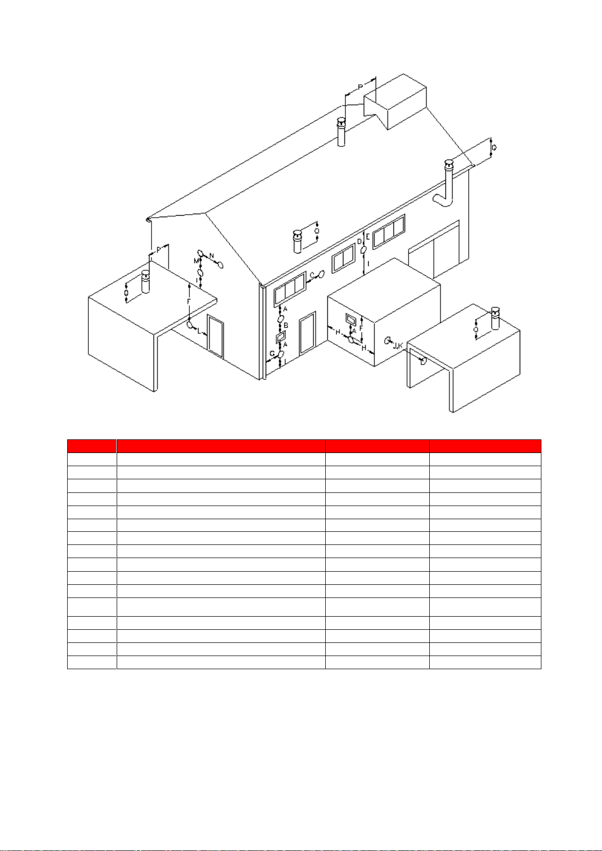
10.4.1 FLUE TERMINAL POSITIONS
Location
Description
EKW46CE – EKW61CE
EKW86CE
A
Directly below an opening, air brick, opening windows etc.
300
2000
B
Above an opening, air brick, opening windows etc.
300
1000
C
Horizontally to an opening, air brick, opening windows etc.
300
1000
D
Below a gutter or sanitary pipework
75
75
E
Below the eaves
200
200
F
Below a balcony or car port roof
200
200
G
From a vertical drain or soil pipe
150
150
H
From an internal or external corner
300
300
I
Above ground, roof or balcony level
300
300
J
From a surface facing the terminal
600
1000
K
From a terminal facing the terminal
1200
2000
L
From an opening in the car port (e.g. door, window) into the
dwelling
1200
1200
M
Vertically from a terminal on the same wall
1500
1500
N
Horizontally from a terminal on the same wall
300
600
P
From a vertical structure on the roof
300
300
Q
Above intersection with the roof
300
300
10.4.2 FLUE TERMINAL MINIMUM DISTANCES
Detailed recommendations for the flue system are given in BS5440-1 for equipment of rated input not exceeding 70kW net, BS6644
for equipment above 70kW net and IGE/UP/10 for equipment of rated input above 54kW net. The following notes are intended to
give general guidance only.
Page 18

18
10.5 APPROVED FLUE SYSTEM
For Concentric and Twin pipe flue systems only the Lochinvar supplied M&G flue system must be used
The approved flue system is not suitable for use external to the building. If external routes cannot be
avoided, a flue system manufacturer should be consulted to supply a suitable alternative.
10.6 INSTALLATION PRECAUTIONS
The approved flue system is rated to 120C max. To prevent the exhaust temperature exceeding this, the appliance is
supplied with a flue gas temperature sensor.
This must be fitted during the installation of the flue system. Failure to do so may lead to severe
personal injury, death or substantial property damage.
The water heater must not be operated unless the complete flue system is installed. This includes the water heater
connections, concentric adaptor (if required) flue pipes, air ducts (if required) and terminals. If discharging at low level, a
suitable flue guard must be installed.
During assembly precaution should be taken to ensure that the internal sealing ring is seated correctly.
Due to the close tolerances in the flue system, it may be necessary to use a twisting action to fit the joints together. No
lubrication other than water should be used.
Page 19
19
10.7 ROOM SEALED (TYPE C) FLUE ASSEMBLY
In order to install the EcoKnight™ water heater with a type C (room sealed) flue system a flue transition kit must first be installed,
this kit is used for both C13 (horizontal) and C33 (vertical) flue systems. The information in this paragraph describes these flue transition
kits and their installation
10.8 INSTALLATION OF FLUE TRANSITION KIT TO EKW46CE – EKW61CE WATER HEATERS
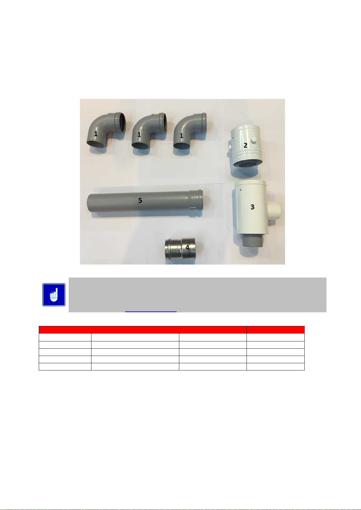
10.8.1 FIGURE 9.2 FLUE TRANSITION PARTS EKW46CE – EKW61CE
Depending upon the flue kit chosen either a vertical or horizontal concentric terminal will be included in
the packaging with the transition kit, additional elbows, flue lengths etc. Are available as ancillary items.
Additional wall brackets may be required to ensure the flue system is stable.
For a full list of flue components supplied and optional parts to complete the system see the EcoKnight™
flue guide available at www.Lochinvar.ltd.uk
ITEM NUMBER
DESCRIPTION
EKW 46CE
EKW 61CE
1
90⁰ ELBOW
3 REQUIRED
3 REQUIRED
2
SAMPLING POINT
1 REQUIRED
1 REQUIRED
3
CONCENTRIC ADAPTOR
1 REQUIRED
1 REQUIRED
4
AIR INTAKE TRANSITION
1 REQUIRED
1 REQUIRED
5
80mm X 500mm LENGTH
CUT TO 270mm
CUT TO 270mm
1.1.1 FLUE TRANSITION PARTS EKW46CE – EKW61CE
Page 20
20
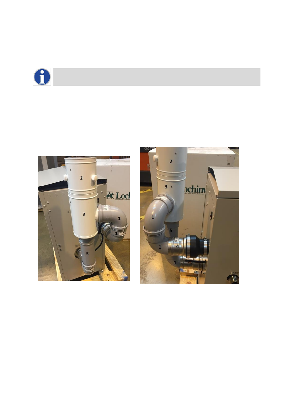
To install the flue connection to the EKW46CE – EKW61CE Water Heaters the following procedure should be followed:
1. Check you have all items shown in Section 10.8.1
2. Check the flue temperature sensor (supplied with the Water Heater) is securely located into the hole on the exhaust
transition.
If the flue temperature sensor is not fitted, the flue gas may exceed the maximum temperature rating of the
flue and can lead to severe personal injury, death or substantial property damage.
3. Insert the air intake transition (Item 4) into the intake connection reducer (shown below) and tighten the worm drive clip.
4. To the bottom (exhaust) connection of the concentric adaptor fit one of the 80mm 90 elbows, and then fit the 80mm
x500mm flue pipe cut to length as in Section 1.1.1To the side (intake) connection of the concentric adaptor, fit the
remaining 90 elbows.
5. Fit the Concentric adapter (item 3) to the exhaust flue pipe and air inlet elbows
6. Fit the flue gas test point (Item 2) and clamp using its locking band.
The completed transition kit should look like the photos shown below.
REAR VIEW TRANSITION KIT EKW46CE-EKW61CE
SIDE VIEW TRANSITION KIT EKW46CE-EKW61CE
10.8.2 TRANSITION KIT FITTED TO APPLIANCE
Page 21
21
10.9 INSTALLATION OF TRANSITION KIT TO EKW86CE WATER HEATERS
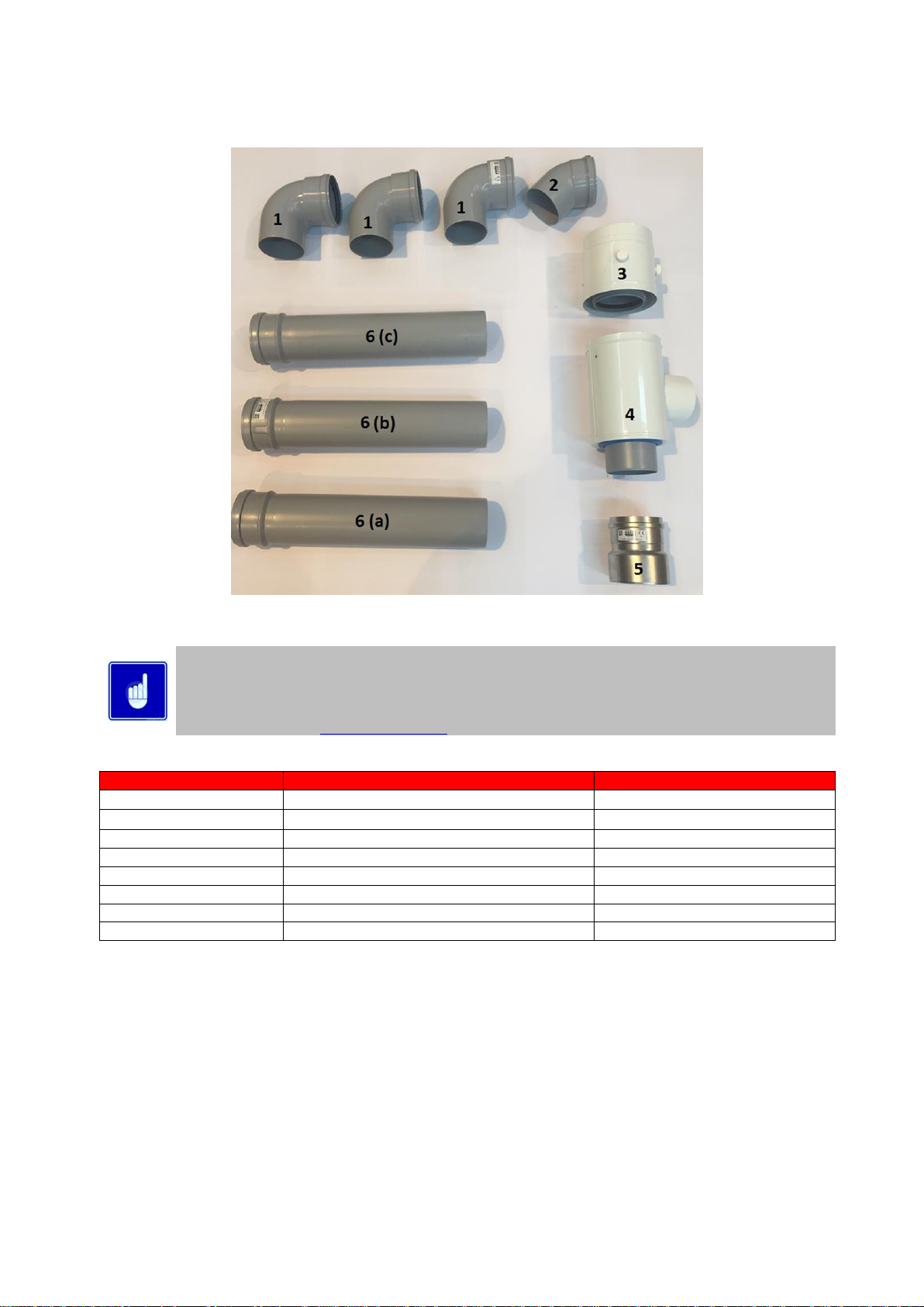
10.9.1 FLUE TRANSITION PARTS EKW86CE
Depending upon the flue kit chosen either a vertical or horizontal concentric terminal will be included in
the packaging with the transition kit, additional elbows, flue lengths etc. Are available as ancillary items.
Additional wall brackets may be required to ensure the flue system is stable.
For a full list of flue components supplied and optional parts to complete the system see the EcoKnight™
flue guide available at www.lochinvar.ltd.uk
ITEM NUMBER
DESCRIPTION
EKW 86
1
90⁰ ELBOW
3 REQUIRED
2
45⁰ ELBOW
1 REQUIRED
3
SAMPLING POINT
1 REQUIRED
4
CONCENTRIC ADAPTOR
1 REQUIRED
5
AIR INTAKE TRANSITION
1 REQUIRED
6 (a)
100mm X 500mm LENGTH
KEEP 500mm
6 (b)
100mm X 500mm LENGTH
CUT TO 330mm
6 (c)
100mm X 500mm LENGTH
CUT TO 330mm
10.9.2 FLUE TRANSITION PARTS EKW86CE
Page 22
22
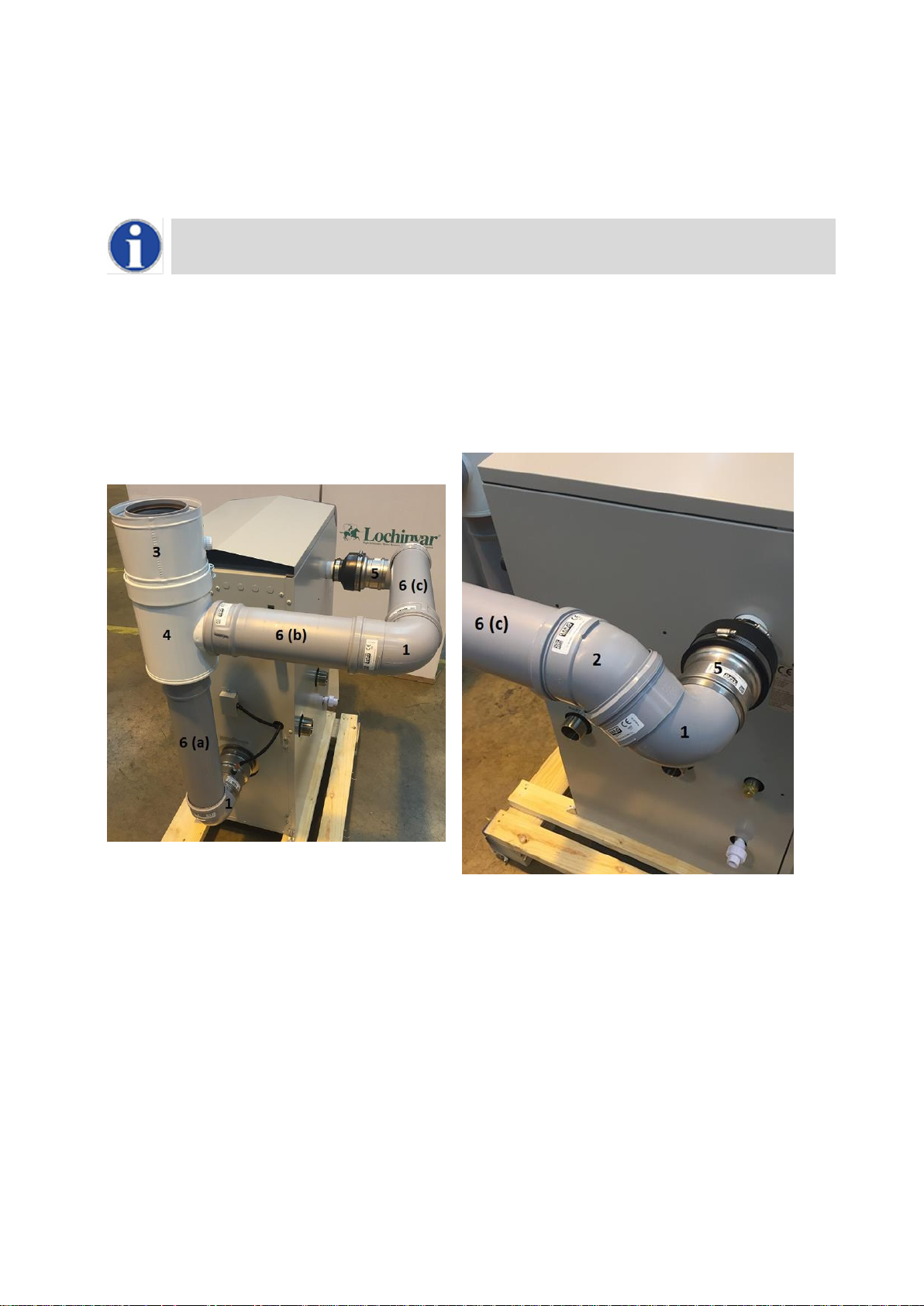
To install the flue connection to the EKW86CE Water Heaters the following procedure should be followed:
1. Check you have all items shown in Section 10.9.2.
2. Check the flue temperature sensor (supplied with the Water Heater) is securely located into the hole on the exhaust
transition.
If the flue temperature sensor is not fitted, the flue gas may exceed the maximum temperature rating of the
flue and can lead to severe personal injury, death or substantial property damage.
3. Insert the air intake transition (Item 5) into the intake connection reducer and tighten the worm drive clip.
4. To the bottom (exhaust) connection of the concentric adaptor fit one of the 80mm 90 elbows, and then fit the 80mm
x500mm flue pipe cut to length as in Section 10.9.2.
5. To the side (intake) connection of the concentric adaptor, fit the remaining 90 elbows.
6. Fit the Concentric adapter (item 3) to the exhaust flue pipe and air inlet elbows
7. Fit the flue gas test point (Item 2) and clamp using its locking band.
The completed transition kit should look like the photos shown below.
REAR VIEW TRANSITION KIT EKW86CE
SIDE VIEW TRANSITION KIT EKW86CE
10.9.3 TRANSITION KIT FITTED TO APPLIANCE
Page 23

23
10.10 C13 CONCENTRIC HORIZONTAL FLUE SYSTEMS
Flue system specifications
MANUFACTURER MUELINK AND GROL (M&G)
TEMPERATURE CLASS T120
FLUE GAS MATERIAL PP
Each concentric horizontal flue kit includes the items shown in the tables below
Item No EKWHF001
CONCENTRIC HORIZONTAL FLUE ASSEMBLY
MODELS EKW46CE,EKW61CE
COMPONENTS INCLUDED
Item No.
Description
Number
Quantity
M85291
BEND 90° 80mm PP
1
3
M84471
SAMPLING POINT Ø80/125mm PP
2
1
M75258
CONCENTRIC ADAPTER TEE Ø80/80mm - Ø80/125mm PP
3
1
M75256
AIR INLET TRANSITION Ø80mm ALU
4
1
M85271
EXTENSION Ø80mm (500mm) PP CUT TO LENGTH
5
1
M84460
CONCENTRIC BEND 90° Ø80/125mm PP
6
1
M86934
CONCENTRIC HORIZONTAL TERMINAL Ø80/125mm PP (NO WALL PLATES)
7
1
M28925
TERMINAL WALL PLATES (PAIR)
8
1
Item No EKWHF002
CONCENTRIC HORIZONTAL FLUE ASSEMBLY
MODELS EKW86CE
COMPONENTS INCLUDED
Item No.
Description
Number
Quantity
M85181
BEND 90° 100mm PP
1
3
M85182
BEND 45° 100mm PP
2
1
M84421
SAMPLING POINT Ø100/150mm PP
3
1
M75259
CONCENTRIC ADAPTER TEE Ø100/100mm Ø100/150mm PP
4
1
M75257
AIR INLET TRANSITION Ø100mm ALU
5
1
M85176
EXTENSION Ø100mm (500mm) PP CUT TO LENGTH
6
3
M84412
CONCENTRIC BEND 90° Ø100/150mm PP
7
1
LV310758
CONCENTRIC HORIZONTAL TERMINAL Ø100/150mm PP
8
1
Page 24
24
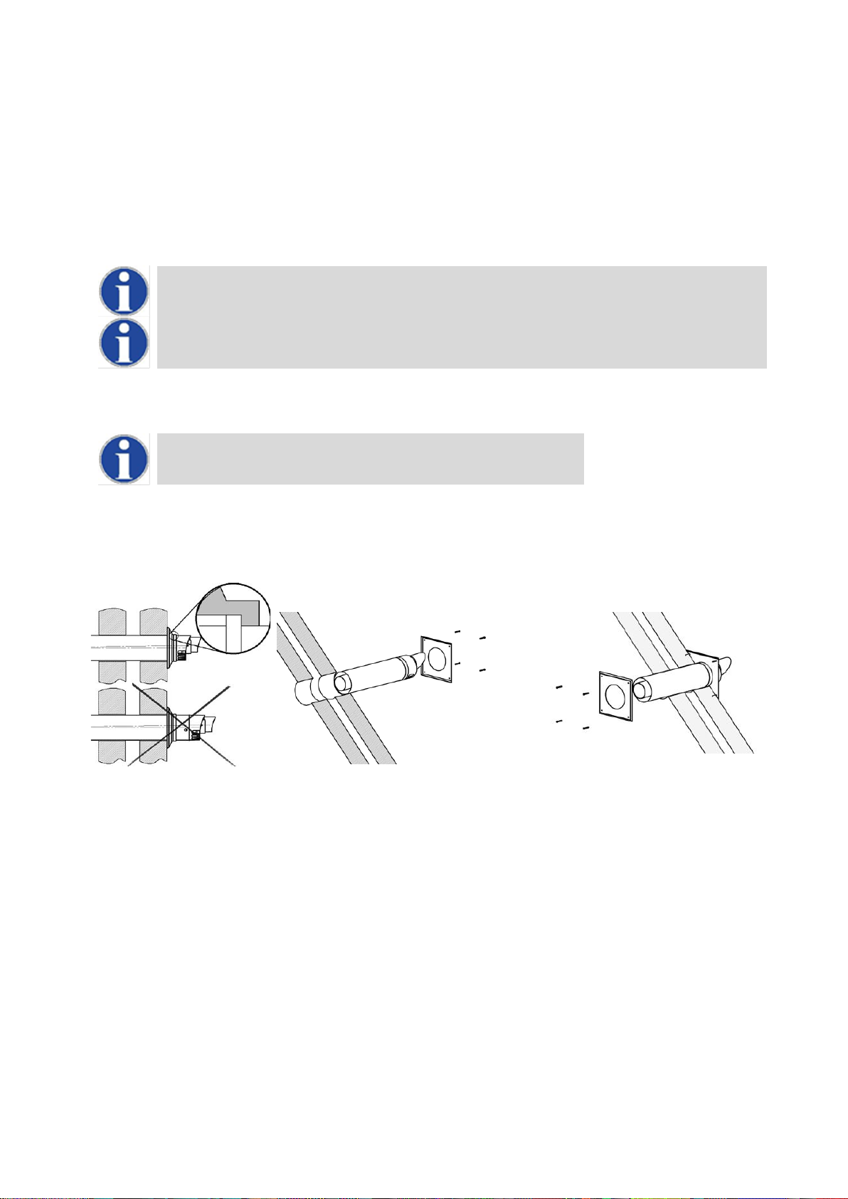
10.11 HORIZONTAL FLUE TERMINAL INSTALLATION
When the Water Heater is installed as a Type C13(Horizontal concentric) appliance, the flue system should be installed as follows:
1. Determine the location of the flue terminal, taking into account minimum distances as detailed in Section 10.4.1 And the
relevant British Standards.
2. Taking care to protect the appliance from debris and dust, drill a hole in the desired location. The diameter of the hole
should be no more than 10mm greater than the diameter of the air supply pipe of the terminal.
3. Determine the required length of the terminal and cut as necessary.
When determining the required length for the flue terminal, the outer wall plate or rosette should be flush
to the wall. (see 10.11.1 )
Once cut; remove all burrs and sharp edges
4. Insert the terminal into the drilled hole. The terminal section should be installed level or with a fall to outside (Max. 10mm
per metre) to prevent the ingress of water.
When inserting the terminal, ensure the air intake section is at the bottom.
5. Fill the void between the terminal and wall with water resistant sealant.
6. Fit the wall plates or rosette using appropriate fixings.
7. Install the remainder of the flue system working progressively away from the Water Heater supporting the pipes as
necessary.
10.11.1 HORIZONTAL TERMINAL INSTALLATION
10.12 FLUE TERMINAL GUARDING
If a horizontal flue terminal is to be fitted less than 2 metres from ground level or in a location where it can be touched from a window,
door or balcony, a terminal guard must be fitted.
Page 25

25
10.13 C33 CONCENTRIC VERTICAL FLUE SYSTEMS
Flue system specifications
MANUFACTURER MUELINK AND GROL (M&G)
TEMPERATURE CLASS T120
FLUE GAS MATERIAL PP
Each concentric horizontal flue kit includes the items shown in the tables below
Item No EKWVF001
CONCENTRIC VERTICAL FLUE ASSEMBLY
MODELS EKW46CE,EKW61CE
COMPONENTS INCLUDED
Item No.
Description
Number
Quantity
M85291
BEND 90° 80mm PP
1
3
M84471
SAMPLING POINT Ø80/125mm PP
2
1
M75258
CONCENTRIC ADAPTER TEE Ø80/80mm - Ø80/125mm PP
3
1
M75256
AIR INLET TRANSITION Ø80mm ALU
4
1
M85271
EXTENSION Ø80mm (500mm) PP CUT TO LENGTH
5
1
LV310744
CONCENTRIC EXTENSION Ø80/125mm(280-395mm) PP TELESCOPIC
6
1
M86864
CONCENTRIC VERTICAL TERMINAL Ø80/125mm PP
7
1
Item No EKWVF002
CONCENTRIC VERTICAL FLUE ASSEMBLY
MODELS EKW86CE
COMPONENTS INCLUDED
Item No.
Description
Number
Quantity
M85181
BEND 90° 100mm PP
1 3 M85182
BEND 45° 100mm PP
2 1 M84421
SAMPLING POINT Ø100/150mm PP
3 1 M75259
CONCENTRIC ADAPTER TEE Ø100/100mm Ø100/150mm PP
4
1
M75257
AIR INLET TRANSITION Ø100mm ALU
5
1
M85176
EXTENSION Ø100mm (500mm) PP CUT TO LENGTH
6 3 M84405
CONCENTRIC EXTENSION Ø100/150 (500mm) PP CUT TO LENGTH
7 1 LV310754
CONCENTRIC VERTICAL TERMINAL Ø100/150mm PP
8
1
Page 26
26
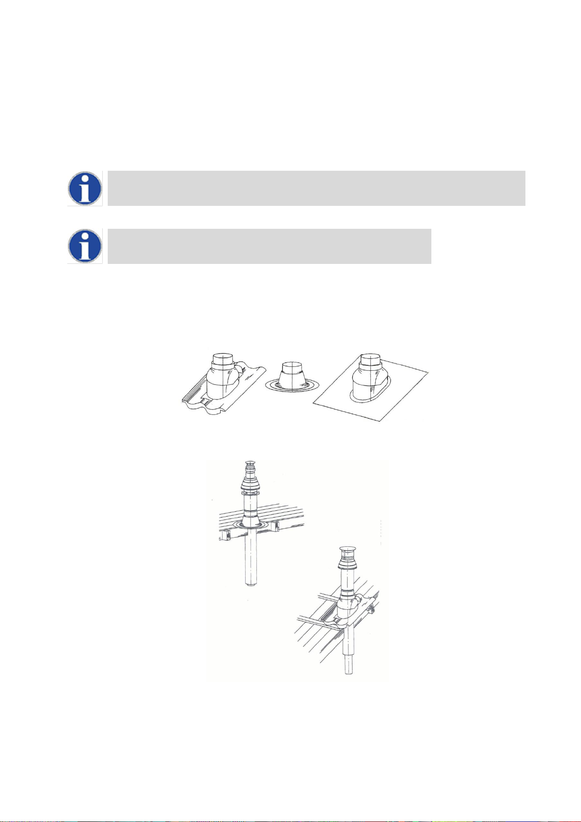
10.14 VERTICAL FLUE TERMINAL INSTALLATION
When the water heater is installed as a Type C33 appliance, the flue system should be installed as follows:
1. Confirm that the roof flashing is correct for the type of roof through which the terminal is to be installed. Section 10.14.1
2. Determine the desired location for the flue terminal, taking into account minimum distances as detailed in Section
10.4.1FLUE TERMINAL POSITIONS and the relevant British Standards.
3. Taking care to protect the appliance from debris and dust, drill a hole in the desired location. The diameter of the hole
should be no more than 10mm greater than the diameter of the air supply pipe of the terminal.
The hole should be drilled from the outside to ensure that no damage is done to the roofing material.
Extra care should be taken to ensure that the hole is drilled vertically.
4. Install the roof flashing and secure as appropriate.
5. Carefully insert the roof terminal through the roof flashing and hole in the roof.
When inserting the roof terminal do not support or turn the terminal using the cap.
6. Ensure the terminal is vertical using a spirit level.
7. Fit the support bracket around the terminal and secure using appropriate fixings. Do not tighten the support bracket
8. Install the remainder of the flue system working progressively away from the water heater supporting the pipes as
necessary.
9. Once the flue system is fully installed, tighten the clamp to secure the terminal in place.
10.14.1 VERTICAL TERMINAL ROOF FLASHINGS FOR SYNTHETIC, FLAT AND TILED ROOFS
10.14.2 INSTALLING TERMINAL THROUGH ROOF FLASHING
Page 27
27
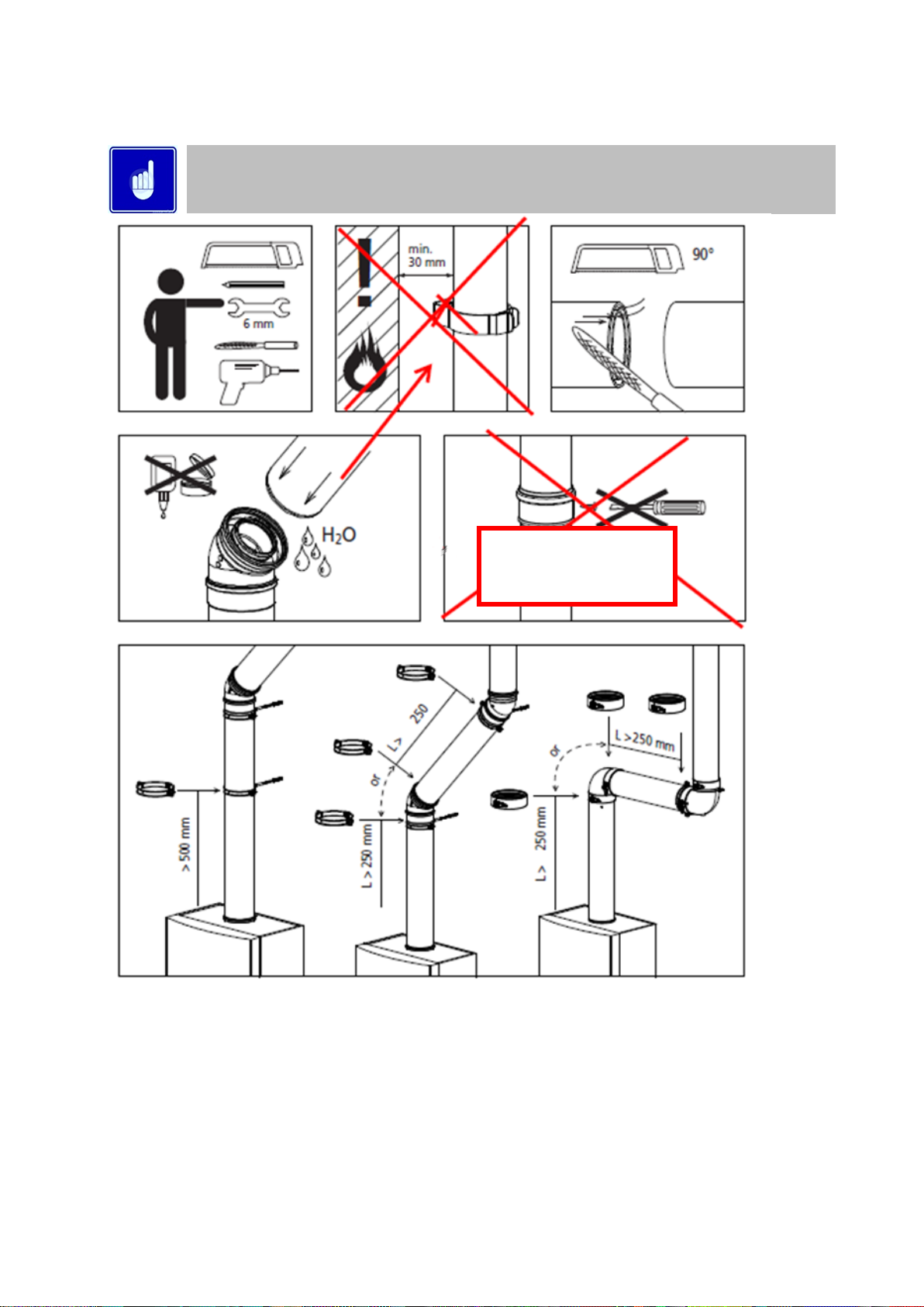
10.14.3 GENERAL CONCENTRIC FLUE SYSTEM INSTALLATION GUIDELINES
The information in this section is for General guidance only and may not fully represent the installation
on site
Do not drill and screw
into flue system
Page 28

28
Max distance between
brackets
Page 29

29
Page 30

30
Page 31

31
10.15 TYPE C
43
(U DUCT)
This appliance can operate on a U-Duct common flue system. The maximum lengths for the interconnecting flue can be found in
Section 10.2.
Concrete components of the U-Duct must meet the requirements of BS EN 1858.
Model No.
Nominal Flue
Diameter
Mass Rate @ 100%
Mass Rate @ 23%
Mass Rate @ 100%
Mass Rate @ 23%
(@ 9% CO2) (G20)
(@ 9% CO2) (G20)
(@ 10.5% CO2) (G31)
(@ 10.5% CO2) (G31)
EKW46CE
80+/-0.6
16.0g/s
3.7g/s
16.7g/s
3.8g/s
EKW61CE
80+/-0.6
22.3g/s
5.1g/s
23.2g/s
5.3g/s
EKW86CE
100+/-0.6
30.4g/s
7.0g/s
31.6g/s
7.3g/s
10.15.1 FLUE GAS MASS RATES
10.16 C
53
(TWIN PIPE) FLUE SYSTEMS
Flue system specifications
MANUFACTURER MUELINK AND GROL (M&G)
TEMPERATURE CLASS T120
FLUE GAS MATERIAL PP
Each Twin-Pipe starter assembly includes the items shown in the tables below
Item No EKWTF001
TWIN-PIPE FLUE STARTER ASSEMBLY
Kit contains components to start the connection to the appliance only
MODELS EKW46CE,EKW61CE
COMPONENTS INCLUDED
Item No.
Description
Number
Quantity
M75256
AIR INLET TRANSITION Ø80mm ALU
1 1 M85279
SAMPLING POINT Ø80mm PP
2
1
Item No EKWTF002
TWIN-PIPE FLUE STARTER ASSEMBLY
Kit contains components to start the connection to the appliance only
MODELS EKW86CE
COMPONENTS INCLUDED
Item No.
Description
Number
Quantity
M75257
AIR INLET TRANSITION Ø100mm ALU
1 1 M85189
SAMPLING POINT Ø100mm PP
2
1
When installing the EcoKnight™ on a C53 twin pipe flue system, the Lochinvar Twin pipe flue starter assembly must be fitted first
including the flue temperature sensor.
Page 32

32
When installing the water heater as a Type C53 appliance, it should be noted that the terminals
must not be installed on opposite sides of the building.
If the flue temperature sensor is not fitted, the flue gas temperature may exceed the maximum
temperature rating of the flue and can lead to severe personal injury, death or substantial property
damage.
Typical Twin-Pipe flue arrangement EKW46-EKW61CE
Typical Twin-Pipe flue arrangement EKW86CE
To install a Type C53 terminal or air inlet, the procedure for either a Type C13 (horizontal) or a Type C33 (vertical) terminal should
be followed noting that the annular space of the terminal should be sealed off.
33
Page 33

10.16.1 GENERAL TWIN-PIPE INSTALLATION GUIDELINES
The information in this section is for General guidance only and may not fully represent the installation
on site
34
Page 34

35
Page 35

Page 36

36
10.17 TYPE B
23
(CONVENTIONAL FLUE WITH FAN ASSISTANCE)
When the water heater is installed as a Type B23 appliance, the flue system should be installed in accordance with the flue
manufacturer’s specific instructions.
Item No EKWCF001
FAN ASSISTED OPEN FLUE STARTER ASSEMBLY
Kit contains components to start the connection to the appliance only
MODELS EKW46CE,EKW61CE
COMPONENTS INCLUDED
Item No.
Description
Number
Quantity
M75256
AIR INLET TRANSITION Ø80mm ALU
1
1
M73039
AIR INLET GRILLE Ø80mm ALU
2
1
M85279
SAMPLING POINT Ø80mm PP
3
1
Item No EKWCF002
FAN ASSISTED OPEN FLUE STARTER ASSEMBLY
Kit contains components to start the connection to the appliance only
MODELS EKW86CE
COMPONENTS INCLUDED
Item No.
Description
Number
Quantity
M75257
AIR INLET TRANSITION Ø100mm ALU
1
1
M86787
APPLIANCE AIR INLET GUARD Ø100mm
2
1
M85189
SAMPLING POINT Ø100mm PP
3
1
The above is a kit of components to facilitate conventional flueing of the appliance and must be fitted prior to fitting any other flue
components.
1.Insert the exhaust transition into the exhaust port of the water heater.
2..Insert the flue temperature sensor into the location hole on the exhaust transition.
If the flue temperature sensor is not fitted, the flue gas may exceed the
maximum temperature rating of the flue and can lead to severe personal
injury, death or substantial property damage.
3.Insert the air intake into the intake connection and tighten the worm drive clip.
4.Insert the air inlet grill into the air inlet transition. For safety reasons this must be fitted prior
to operating the appliance.
10.17.1 TYPICAL CONVENTIONAL FLUE ARRANGEMENT
Page 37

37
10.18 C63 CERTIFIED FLUE SYSTEMS
In general, Water heaters are certified with their own purpose supplied Concentric or Twin Pipe flue systems, C63 certified appliances
allow the installer to use other flue systems when installing the Water heater however, they must be of a suitable minimum standard
as per Table below.
CE string
flue gas
material
European standard
Tempera
-ture
class Pressure class Resistance to
condensate Corrosion
resistance
class Metal: liner
specifications
Soot fire
resistance
class
Distance to
combustible
material
Plastics:
location Plastics: fire
behaviour
Plastics:
enclosure
min. eis PP
EN 14471
T120
P1 W 1 O
30
I of E
C/E
L
min. eis RVS
EN 1856-1
T120
P1 W 1
L20040
O
40
10.18.1 C63 FLUE SYSTEM SPECIFICATION
Material
Water heater
d
nom
D
outside
d
inside
L
insert
PP
EKW46 CE
80
80 +/-0.6
50 +20/ -2
PP
EKW61 CE
80
80 +/-0.6
50 +20/ -2
PP
EKW86 CE
100
100 +/-0.6
50 +20/ -2
Aluminium flue pipe must not be used on this appliance as it may lead to premature failure of the heat
exchanger and will invalidate the warranty.
Page 38

38
11.0 AIR SUPPLY
The following information is based on single water heater installations only. If more than one water heater is being used, BS5440-2
or BS6644 (as appropriate) should be consulted to calculate the necessary requirements.
11.1 COMBUSTION VENTILATION
When used as a Type C (room sealed) appliance, provided sufficient clearance is provided, ventilation for combustion is not
necessary as the combustion air is ducted directly from outside.
When used as a Type B (open flue) appliance, the combustion air requirements are as follows:
Model
Gross
Input
(kW)
Net
Input
(kW)
Ventilation
(Room)
(cm2)
Compartment
Compartment
(Direct to Outside)
(To Internal Space)
High
(cm2)
Low
(cm2)
High
(cm2)
Low
(cm2)
EKW46CE
43.9
39.6
165
200
400
400
800
EKW61CE
58.6
52.8
230
265
530
530
1060
11.1.1 COMBUSTION VENTILATION REQUIREMENTS EKW46CE – EKW61CE
Model
Input
(Gross)
kW
Input
(Net)
kW
Plant Room
Enclosure
Low
Summer Use
Medium
Summer Use
High
Summer Use
Low
Summer Use
Medium
Summer Use
High
Summer Use
High
(cm2)
Low
(cm2)
High
(cm2)
Low
(cm2)
High
(cm2)
Low
(cm2)
High
(cm2)
Low
(cm2)
High
(cm2)
Low
(cm2)
High
(cm2)
Low
(cm2)
EKW86CE
83.5
75.3
152
304
228
380
304
456
380
760
456
836
532
912
11.1.2 COMBUSTION VENTILATION REQUIREMENTS EKW86CE
11.2 COOLING VENTILATION
When used as a type C (room sealed) appliance, installed in a compartment or an enclosure, as shown in Figure 5.2.1, cooling
ventilation should be provided as follows:
Model
Input
(Gross)
kW
Input
(Net)
kW
Enclosure/Compartment
Enclosure/Compartment
Water heater Room
(Direct to Outside)
(To Internal Space)
High
(cm2)
Low
(cm2)
High
(cm2)
Low
(cm2)
High
(cm2)
Low
(cm2)
EKW46CE
43.9
39.6
200
200
400
400
N/A
N/A
EKW61CE
58.6
52.8
265
265
530
530
N/A
N/A
EKW86CE
83.5
75.3
380
380
760
760
152
152
11.2.1 COOLING VENTILATION REQUIREMENTS
When used as a type B (open flue) appliance, provision for cooling ventilation is included in the combustion ventilation allowance.
Page 39

39
12.0 WATER CONNECTIONS
12.1 GENERAL
Adaptors are required to convert the NTP (male) thread on the heat exchanger to BSP (female). These
adaptors can be found in the packing carton. The BSP section of the adaptor is indicated with blue paint.
EcoKnight™ water heaters require a minimum flow rate and must be installed with separate
storage vessels. Suitably sized pumps and separate storage vessels are available from
Lochinvar limited as ancillary options.
Lochinvar limited insists on the use of glanded pumps and a suitably sized pump will always
be quoted alongside the water heater. Failure of the heat exchanger or other components due
to insufficient flow will not be covered under the warranty.
Recommended pipework layouts are available for different water heater and storage vessel combinations. Please contact Lochinvar
Technical Support for details.
The requirements of minimum water flow are given in Table 12.4.1. Recommendations for the water circulation system are given in
BS6644 and CP 342. The following notes are of particular importance.
1. EcoKnight™ must be used with a direct type storage vessel (LST). Contact Lochinvar Limited for help in sizing the storage
vessel.
2. Circulating pipework not forming part of the useful heating surface should be insulated. Cisterns, expansion vessels and
pipework situated in areas exposed to freezing conditions should also be insulated.
3. Drain valves must be located in accessible positions that will permit draining of the entire system including the unit and the
storage vessel.
4. Tapping sizes for connection to the water system are detailed in Section 4.0.
5. Ideally, individual valves should be fitted to each unit to enable isolation from the system. The arrangement must comply
with the requirements of BS6644.
6. The flow and return circulating pipework must be correctly sized to ensure the water heaters can supply sufficient hot water,
general guidance is provided in Section 0 If your installation is outside this guidance please contact Lochinvar Technical
Support for assistance with pipework sizing.
Page 40

40
12.2 OPEN VENTED SYSTEM ARRANGEMENT
The Lochinvar EcoKnight™ can be used in an open vented arrangement provided that a vent pipe in accordance with CP342,
BS6644 or BS6700 as appropriate is fitted. The minimum static head requirement for an open vented system is 0.5 bar.
12.2.1 TYPICAL SCHEMATIC, ECOKNIGHT™ WATER HEATERS ON AN OPEN VENTED SYSTEM
12.3 UN-VENTED SYSTEM ARRANGEMENT
If the Lochinvar EcoKnight™ is to be used in an unvented arrangement, the system should follow the guidance given in BS6700 and
must comply with The Building Regulations: Part G3 in England and Wales, P5 in Northern Ireland and P3 in Scotland. A kit
of components that have been suitably sized for the unvented or boosted operation of the appliance is available from Lochinvar
Limited. For further information, contact Lochinvar Limited.
12.3.1 TYPICAL SCHEMATIC, ECOKNIGHT™ WATER HEATER ON AN UN-VENTED SYSTEM
Page 41

41
12.3.2 EXPANSION VESSEL SIZING
The following information is based on an inlet pressure of 3.5 bar and an expansion vessel efficiency of 0.45 using a standard 6 bar
unvented kit. If the system will have different parameters a more detailed calculation will need to be made.
V V = S V * e
0.45
Where:
V V = Vessel Volume
S V = System Volume
e = Coefficient of Expansion
Stored Temp.
C
30
35
40
45
50
55
60
e
0.005
0.006
0.008
0.010
0.012
0.015
0.017
Stored Temp.
C
65
70
75
80
82
85
90
e
0.020
0.023
0.026
0.030
0.031
0.033
0.037
12.3.3 COEFFICIENT OF EXPANSION OF WATER AT 3.8 BAR COLD FILL PRESSURE
12.4 CIRCULATING PUMPS
In order to ensure the correct flow rates through the water heater, the unit requires a bronze glanded pump sized to overcome the
resistance of the heat exchanger and a primary pipework loop. Lochinvar will supply a suitable bronze glanded shunt pump with
each water heater as shown in Section 12.4.1. The primary loop should be no longer than 14 metres plus the following fittings:
6 x 90 Elbows
2 x Unions
2 x Full bore lever ball valves
2 x Tee fittings (cold feed & building return)
For longer distances or a greater number of fittings, the pump may have to be resized.
The specification of this type of pump ensures that the bronze body and associated parts in contact with water are suitable for potable
use. A "glanded" construction is required to ensure that any scale in the system does not build up within the pump and cause a
resistance that can lead to a loss of water flow. Glandless (canned rotor) pumps are not recommended due to the fact that in hard
water areas, scale can build up within the rotor and failure can occur, not only of the pump but also the heater itself. The warranty
will be void if a failure of the heat exchanger occurs due to a "glandless" pump being used.
Model
Differential (K)
FLOW
(Litre/sec)
Total System Pressure
Loss (Meter- H20)
Shunt Pump supplied
EKW46CE
10.0
0.98
7.32
LM900151A
EKW61CE
10.0
1.17
6.71
LM900151A
EKW86CE
10.0
1.80
6.07
LM900141A
12.4.1 FLOW RATES AND SHUNT PUMP SIZES
Lochinvar will supply a suitably sized pump with all EcoKnight™ water heaters based on the parameters shown above, for projects
outside these parameters the pump will have to be re-sized.
Page 42

42
12.5 PRIMARY PIPEWORK HEADER SIZING
The pipework header between the EcoKnight™ water heater(s) and LST(s) buffer vessels must be sized as
per the guidance given in this section. Failure to use the correct size of pipe header will cause operational
problems and potential early failure of the water heater; this will not be covered under the water heater
warranty.
If your installation is outside the scope of this guidance, please contact Lochinvar Technical support before
proceeding with the installation.
The tables below show the pipework header sizing required in order to ensure the correct flow rate is maintained between the
EcoKnight™ water heater and the LST direct storage vessel. Using the simple schematics shown in section 12.5.2 size the pipework
header A shown in blue and pipework header B shown in red.
Using the example schematics shown and assuming the EcoKnight™ is an EKW46CE in both cases the header would be sized as:
Single unit = as there is only a single heater there is no common header so all the pipework should be 35mm.
2 units = the common header shown in red should be sized according to the table at 42mm with the pipework between the header
and each individual units shown in blue at 35mm.
MODEL
PIPEWORK A BLUE SIZE (mm)
PIPEWORK B RED SIZE (mm)
NUMBER OF ECOKNIGHT™
1
2 3 4
EKW46CE
35
42
54
67
EKW61CE
35
42
54
67
EKW86CE
54
54
67
76
12.5.1 PIPEWORK HEADER SIZES
12.5.2 PIPEWORK SCHEMATIC SHOWING PIPEWORK A AND PIPEWORK B
13.0 CONTROL OPTIONS/INSTALLATION
The EcoKnight™ water heater has various control options available, depending upon the installation and if there is a BMS available.
The relevant wiring diagram should be consulted along with information shown in Section 15.0
Lochinvar Ltd reserves the right to change specifications without prior notice. All necessary additional
valves and fittings to be determined by those other than Lochinvar Ltd. Lochinvar Ltd may provide technical
advice and guidance to assist with best practice, optimisation and installation of Lochinvar products;
however, we will not be liable for any duties as Designers under Construction (Design and Management
Regulations 2015). In all cases where information is provided, the customer must assess and manage risks
associated with the technical information and advice provided.
Page 43

43
13.1 VESSEL TEMPERATURE SENSOR SINGLE WATER HEATER INSTALLATION
Each EcoKnight™ is supplied with a vessel temperature sensor and sensor pocket. This must be fitted to the LST direct storage
vessel supplied with the EcoKnight™ water heater.
This is installed within the vessel as close to the flow and return connections as possible depending upon vessel chosen see diagram
13.1.1. Point 7
On systems with multiple storage vessels it is recommend that the water heaters only read the
temperature of a single vessel, the vessels should be balanced so they are all the same temperature.
13.1.1 TYPICAL LST CONNECTION POINTS
1.1 VESSEL TEMPERATURE SENSOR MULTIPLE WATER HEATER INSTALLATION
When installing multiple water heaters it is recommended that the water heaters are installed using the cascade management system,
see section 21.6. When in cascade only the lead water heater and alternate lead have tank sensors fitted see 1.1.1. The lead water
heater will monitor the tank temperature and control the water heaters within the cascade, in the event of a failure of the lead water
heater then the alternate leader will take over control of the system, hence it is also required to have a tank sensor fitted.
It may not be possible to fit two sensors into a single tank when using a cascade system with lead/alternate
lead. If there are two tanks then the alternate lead can have its sensor placed in the second tank see 14.4.1,
due to the fact the vessels should be balanced then the temperature will be the same in both tanks. If the
system only has a single tank then the alternate lead will need to use a strap on sensor located onto the
pipework near to the tank see 14.2.1 – this is less accurate but will allow the system to continue operating
whilst the lead water heater is repaired.
13.2 SENSOR WIRING
For guidance on installing the wiring for the temperature sensor, please refer to Section: 15.4.1
Page 44

44
14.0 SCHEMATICS
1.1 KEY FOR SCHEMATICS
Lochinvar limited may provide technical advice and guidance to assist with best practice, optimisation and
installation of Lochinvar products; however, we will not be liable for any duties as designers under
construction (design and management regulations 2015). In all cases where information is provided, the
customer must assess and manage risks associated with the technical information and advice provided.
SYMBOL
DESCRIPTION
IV
ISOLATION VALVE
LSV
LOCKSHIELD VALVE
TPRV
TEMPERATURE AND PRESSURE RELEIF VALVE
TD
TUNDISH
EXV
EXPANSION VESSELQ
EV
EXPANSION VALVE
PRV
PRESSURE REDUCING VALVE
NRV
NON RETURN VALVE
PCP
PRIMARY CIRCULATING PUMP
TS
TEMPERATURE SENSOR (VESSEL SENSOR)
JB
JUNCTION BOX
BRP
BUILDING RETURN PUMP
PCP
PRIMARY CIRCULATING PUMP
RLY
RELAY
SS
STRAP ON PIPE SENSOR
Page 45

45
14.1 STANDALONE INSTALLATION, SINGLE WATER HEATER
The installation shown below features an EcoKnight™ water heater working on its own sensors only, the supplied tank sensor is
installed within the sensor point on the LST direct storage vessel. This arrangement gives close temperature control and is particularly
suitable for installations with a constant low level demand such as leisure centres. The EcoKnight™ water heater shunt pump will
continue to run for a short period after the burner has stopped firing to clear any residual heat from the heat exchanger. See 21.8.1.
14.1.1 STANDALONE INSTALLATION
Page 46

46
1.1 BMS INSTALLATION, SINGLE WATER HEATER
The installation shown below features an EcoKnight™ water heater with BMS control, the BMS can send an on/off signal as required
depending upon the temperature within the storage vessel. This will be monitored by a BMS sensor shutting the EcoKnight™ water
heater down when the vessel is at set point. This application gives greater control and is suitable for installations when th e DHW
demand is intermittent such as hotels. The EcoKnight™ water heater shunt pump will continue to run for a short period after the
burner has stopped firing to clear any residual heat from the heat exchanger. See 21.8.1.
14.1.2 SINGLE WATER HEATER WITH BMS CONTROL
Page 47

47
14.2 INSTALLATION, TWO WATER HEATERS WITH SINGLE VESSEL – ALTERNATE LEAD WITH STRAP-ON SENSOR
The installation shown below features two EcoKnight™ water heaters working with a single tank sensor. The water heaters would
be put into cascade - the supplied tank sensor is installed within the sensor point on the LST direct storage vessel and connected
back to the lead water heater. The alternate leader has a strap-on sensor fitted to the pipework.
14.2.1 MULTIPLE WATER HEATERS SINGLE VESSEL ALTERNATE WITH STRAP-ON SENSOR
Page 48

48
14.3 MULTIPLE WATER HEATERS WITH SINGLE VESSEL
When multiple EcoKnight™ water heaters are installed as shown below one water heater is designated as the leader water heater.
The leader will decide how many member water heaters to activate and at what firing rate depending upon information received from
the tank sensor. This will increase the system efficiency as this closer control prevents the water heaters cycling at low demand. The
water heaters should be piped on a reverse return arrangement.
1.1.1 MULTIPLE WATER HEATERS WITH CASCADE CONTROL ALTERNATE WITH ADDITIONAL TANK SENSOR FITTED
Page 49

49
14.4 MULTIPLE WATER HEATERS WITH MULTIPLE LST DIRECT STORAGE VESSELS
Sometimes it may be necessary to install multiple LST direct storage vessels, for example to reduce the kW required meeting t he
demand or if a single larger vessel will not fit within the plant room. The vessels should be installed as shown below utilising a reverse
return pipework arrangement to ensure an even temperature distribution between the vessels. The water heaters should be put into
cascade with the lead water heater monitoring the tank temperature. Due to the fact there is more than one vessel; the alternate
lead can have a sensor in one of the additional tanks.
14.4.1 MULTIPLE WATER HEATERS WITH MULTIPLE LST DIRECT STORAGE VESSELS – ALTERNATE LEAD USING TANK SENSOR IN ADDITIONAL VESSEL.
Page 50

50
15.0 ELECTRICAL SUPPLY
Wiring external to the equipment must be installed in accordance with the I.E.E. Regulations and any local regulations that
apply.
Model
Normal Supply Voltage
External Fuse Rating
Power Consumption
EKW46CE
230V AC
50 Hz
1 PH
6.0 A
120 W
EKW61CE
144 W
EKW86CE
180 W
15.1.1 ELECTRICAL SUPPLY REQUIREMENTS
Warning: this appliance must be earthed
A suitably competent person must check wiring. Normal supply required is 230 volts’ AC, single phase,
50 hz. An isolator with a contact separation of at least 3mm in all poles should be sited close to the
equipment and must only serve that equipment. The double pole switch must be readily accessible
under all conditions
15.2 EXTERNAL CONTROLS
The EcoKnight™ Water Heater can be controlled via a BMS system either utilising a simple on/off arrangement or by directly
modulating the output. The Water Heater has the following inputs/outputs:
Building Management System (BMS) 0-10VDC analogue input
Volt-free “burner on” (runtime) signal
Volt-free “lock-out” (alarm) signal
0-10V “burner firing rate”
0-10V “Water Heater pump speed”
24VAC auxiliary device enable signal (e.g. to start fan dilution system)
The EcoKnight™ Water Heater is also compatible with the following control and safety systems allowing the Water Heater to operate
as a complete standalone system. See the relevant sections within Section 21.0 for details of programming the various functions
required for a standalone system.
Storage vessel sensor (modulating type)
Internal Cascade control
Gas pressure switch (e.g. gas booster under pressure/over pressure safety switch)
Water flow proving device (e.g. differential pressure switch or flow switch)
Auxiliary safety system proving switch (e.g. fan dilution system proving switch)
Page 51

51
15.2.1 REMOTE ENABLING
There are three ways to enable the EcoKnight™ Water Heater as follows;
1. Using night setback mode – this uses the EcoKnight™ water heaters internal clock and can be used to program 7 stop
times and 7 start times. Refer to section 21.1
For more intermittent control of the EcoKnight™ water heater then the BMS function can be used as follows;
2. Using a 0-10V signal via connections 35-36 and referring to section 21.7
Enable BMS and set type to set point
Set point at minimum volts should be your required minimum set point (50⁰C for example)
Set point at maximum volts should be your required set point (60⁰C for example)
Volts at minimum should be set to 2V
Volts at maximum should be set to 10V
To enable the EcoKnight™ water heater supply a voltage above the minimum voltage on the 0-10V input 10 V
10V will give the maximum set point, lower voltages will adjust the set point.
To disable the EcoKnight™ water heater drop the voltage to below the minimum voltage (below 2V in this
example) and the water heater will have no demand.
It is possible to vary your set point using this method by altering the voltage supplied to the 0-10V input, you may wish to have a set
point of 70⁰C at 10V and then run the unit at say 8V to achieve 60⁰C and then to run a pasteurisation cycle lift the voltage to 10V
thus increasing the set point to 70⁰C.
3. Using a volt free enable signal via connections 15-16 referring to section 21.7
If the building does not have a BMS but you wish to enable at intermittent times meaning the night setback function is not
possible, then the BMS functions can still be used as follows;
Enable BMS and set type to set point
Set point at minimum volts should be your required set point (60⁰C for example)
Set point at maximum volts should be your required set point (60⁰C for example)
Volts at minimum should be set to 0V
Volts at maximum should be set to 0V
Set BMS thermostat input to active
Now use terminals 15 and 16 tank thermostat and run to your enable relay – the EcoKnight™ water heater will
be enabled/disabled by making and breaking connections 15&16
Page 52

52
15.3 HIGH VOLTAGE CONNECTOR STRIP
15.3.1 HIGH VOLTAGE CONNECTION STRIP
The output across the 3 terminals should not exceed 190W per terminal.
It is highly recommended these switched outputs are only used to switch suitable
starter/overload relays on the pumps.
CONNECTION
OUTPUT
NOTES
PRIMARY
230VAC – Output is when there is a call for DHW
MAX 190 WATTS
230 VAC Live, Neutral and Earth connections for a primary
circulation pump starter.
NOTE: On all EcoKnight™ water heaters, the primary pump
exceeds the maximum power output and therefore a suitable
starter/overload relay will be required.
DE-STRAT
NO OUTPUT
CONNECTION NOT USED
RETURN
230VAC – Constant output when unit powered
MAX 190 WATTS
230 VAC Live, Neutral and Earth connections for a secondary
circulation pump. If the pump rating exceeds the maximum 190
watts available over the three terminals, the Live and Neutral
connections should then be used to switch a suitable
starter/overload relay.
MAINS
Connections for a 230V ~ 1 ph 50Hz power supply. NOTE: The
power supply cable should be secured using the anchor supplied.
15.3.2 HIGH VOLTAGE CONNECTION TERMINAL DETAILS
15.4 LOW VOLTAGE CONNECTOR STRIP
The low voltage connector strip is used on both EcoKnight water heaters and Herald boilers; as
such, some connections will not be applicable to your installation.
15.4.1 LOW VOLTAGE CONNECTION STRIP
Page 53

53
PIN
CONNECTION
OUTPUT / INPUT
NOTES
1-2
ALARM CONTACTS
Volt free – Close on alarm
An internal volt free contact across pins 1 and 2 will close in the event of the heater locking
out. This connection can be used by a BMS to monitor the operation of the heater.
3-4
RUNTIME
CONTACTS
Volt free – Close when unit
running
An internal volt free contact across pins 3 and 4 will close in the event of the burner
operating. This connection can be used by a BMS to monitor the operation of the heater
5-6
24VAC RECIRC
PUMP
RELAY COIL
24VAC Output – when
recirc sensor calls –
switches on Neutral
When the heater gets a call for heat from the DHW RECIRC SENSOR a 24VAC supply will
be sent to a DHW recirculation pump relay (field supplied)
7-8
24VAC LOUVER
RELAY COIL (COM)
24VAC Output – When unit
calls for heat.
When the heater gets a call for heat, a 24VAC supply becomes present on pin 7. Used in
conjunction with the ground pin (pin 8), these terminals can be used to send a signal to
energise an auxiliary device such as a fan dilution system or mechanical ventilation system.
9-10
LOUVER PROVING
SWITCH
24VAC Output – When unit
calls for heat.
If an auxiliary device such as a fan dilution system or mechanical ventilation system is to be
used, the link should be taken out of pins 9 and 10 and the auxiliary deice safety circuit
wiring installed. If there is no continuity across the terminals the heater will not fire.
11-12
GAS PRESSURE
SWITCH
24VAC Output – constant
when unit is powered
If a gas pressure switch is to be used to ensure the incoming gas pressure is correct, the
link should be taken out of pins 11 and 12 and the gas pressure switch wiring installed. If
there is no continuity across the terminals the heater will not fire.
1314
FLOW SWITCH
24VAC Output –
constant when unit is
powered
If a flow switch is to be used to ensure the primary pump is operating, the link should be taken out of
pins 13 and 14 and the flow switch wiring installed. If there is no continuity across the terminals the
heater will not fire.
1516
TANK
THERMOSTAT
24VAC Output –
constant when unit is
powered
This connection should not be used for controling DHW temperature. The supplied temperature sensor
should be connected to pins 29 & 30. For further information, please refer to Section 13.0:
The Tank thermostat can be used as an enable – when a tank sensor is fitted and the BMS
Thermostat is enabled see section 15.2.1 The tank sensor (terminals 29 & 30) is still used for
temperature control, the thermostat connection just used to enable.
1718
HEAT/LOOP
DEMAND 3
24VAC Output –
constant when unit is
powered
This connection should not be used with a water heater.
1920
HEAT/LOOP
DEMAND 2
24VAC Output –
constant when unit is
powered
This connection should not be used with a water heater.
2122
HEAT/LOOP
DEMAND 1
24VAC Output –
constant when unit is
powered
This connection should not be used with a water heater.
2324
SYSTEM
SENSOR
Contacts read a
resistance
This connection should not be used with a water heater.
2526
OUTDOOR
SENSOR
Contacts read a
resistance
This connection should not be used with a water heater.
2728
DHW RECIRC
SENSOR
Contacts read a
resistance
The heater can control a DHW recirculation pump. A sensor must be installed in the circulation loop
return and connected to terminals 27 and 28.
2930
TANK
SENSOR
24VAC Output – When
unit calls for heat.
A sensor located in the direct vessel must be connected to terminals 29 and 30 to control the output
from the heater. This connection is not polarity sensitive. This sensor is included with the EcoKnight™
water heater.
3134
CASCADE
Communication
If the heaters are to be operated in a cascade, shielded 2-wire twisted pair communication cable should
be used. The shielding should be connected to pin 31 or 34 and then all “A” terminals (pin 32) should
be linked together and all “B” terminals (pin 33) should be linked together.
3536
BMS IN
0 – 10 V DC
input
When the heater is to be controlled by a 0-10V DC analogue output from a Building Management
System (BMS), the 0V line should be connected to pin 35 and the 0-10V line should be connected to
pin 36. See section 21.7
3738
SYS PUMP IN
0 – 10 V DC
input
This connection should not be used with a water heater.
3940
BLR PUMP OUT
0 – 10 V DC
output
This connection should not be used with a water heater.
4142
RATE OUT
0 – 10 V DC
output
Provides a 0-10V signal that is proportional to the firing rate of the heater. This may be used by a BMS
system to monitor the actual rate of the heater.
4346
MODBUS/BACNET
OPTION
Communication
When an optional ModBus or BACnet interface module is installed the RS-485 cable is connected to
these terminals
15.4.2 LOW VOLTAGE CONNECTION TERMINAL DETAILS
Page 54

54
15.5 ELECTRICAL CONNECTIONS
Access to the High Voltage and Low Voltage Connection Strips can be made by removing the appropriate knockouts on the back
panel of the water heater. All connections should be secured using an appropriate cord anchorage. One cord anchor is supplied
with the water heater for securing the mains supply to the unit. If additional controls and ancillaries are to be used, the appropriate
knockout should be removed and an anchor such as RS Components part number 607-897 plus locking nut 444-3085 should be
fitted.
If a knockout is removed by mistake, the resulting hole must be blocked with an appropriate anchor,
plug or grommet to prevent accidental access to the live parts within the water heater.
15.6 FUSES
The EcoKnight™ has three internal fuses. All are slow blow fuses, located and rated as follows:
15.6.1 FUSE RATINGS AND LOCATIONS
The EcoKnight™ has three internal fuses. All are slow blow fuses, located and rated as follows:
F1
5 A
F2
3.15A
F3
80A
The water heater has three spare fuses in a plastic bag attached to the control module cover. Only replace with an equivalent rated
fuse. Use of non-equivalent fuses or link wires will invalidate the warranty.
15.7 ARC WELDING PRECAUTIONS
The appliance must be isolated from the mains electricity supply in the event of electric arc welding being carried out on any
connecting pipework.
F3
F1
F2
Page 55

55
15.8 WIRING DIAGRAM
15.8.1 WIRING DIAGRAM
Page 56

56
15.9 LADDER DIAGRAM
15.9.1 LADDER DIAGRAM
Page 57

57
16.0 SMART SYSTEM CONTROL
16.1 GENERAL
The Lochinvar EcoKnight™ uses the SMART SYSTEM control interface. The control panel display give information on set-up,
system status and diagnostic data in words rather than codes.
16.2 SMART SYSTEM CONTROL PANEL
1
USB Drive
2
PC Connection
3
Left select key
4
Navigation dial
5
Reset switch
6
Right select key
The information on the bottom of the display shows the functions of the two SELECT keys on both corner, and the NAVIGATION
dial in the centre.
MENU
Left SELECT key
SETPOINTS
NAVIGATION dial-pressing down
SHDN
Right SELECT key
The smart system control face instantly informs the user of the status of the Water Heater by changing colour according to the status
of the Water Heater as below.
Normal operation
Service required
Water heater Locked out
16.3 ACCESS MODES
16.3.1 USER
The user can adjust tank target temperatures by pressing the NAVIGATION dial when “↓SETPOINTS” is flashing at the bottom of
the display. The date, time and the temperature units can also be changed.
16.3.2 INSTALLER
Most parameters are available only for the installer, accessible by entering the installer password.
1
2
3
4
6
5
Page 58

58
16.4 SAVING PARAMETERS
Please note that the brackets ([]) denote screen status.
16.4.1 TO SAVE PARAMETERS AND EXIT PROGRAMMING
Press the RIGHT SELECT (SAVE) key and then press the RIGHT SELECT (HOME) KEY.
16.4.2 TO ENTER A PARAMETER AND CONTINUE PROGRAMMING
Press the RIGHT SELECT (SAVE) key 1 time to return to the parameter listings, press again to return to the menu listings. Remember
to press the RIGHT SELECT key when programming is completed in order to save the changes made.
Operation
Display
1
Upon a call for heat , the gas pressure switch(s) must be closed
2
Once the gas pressure switch(s) are closed the control turns on the appropriate
pumps. The flow switch and or LWCO must close
3
The control turns on power to the louvre relay, the louvre proving switch and
blocked drain switch must close
4
The control starts the pre-purge cycle by initiating the fan
5
The control starts the trial for ignition by firing the spark electrode and opening the
gas valve
Page 59

59
6
If flame is not detected after spark ends the control will perform a post-purge, then
start another pre-purge cycle and try to light the water heater again. On the 145
model up the control will lock out after this second attempt on the 115 down a
further four attempts will be made before the unit goes to lock-out.
7
If the flame is detected it holds the firing rate steady for a few seconds then begins
to modulate the firing rate based on a set point or some other command (such as
the 0-10v signal)
8
Once the call for heat is satisfied the control will turn off the burner. The fan will
continue to run during the post-purge period.
9
Any pumps that are running will continue for their respective pump overrun time
period before switching off. A 60 second anti-cycle period will start which will delay
any call for heat.
10
In standby ready to start a new cycle.
1.1.1 SEQUENCE OF OPERATION
Page 60

60
16.5 STATUS DISPLAY SCREENS
Section
Display
Description
A (Water
heater
status bar)
STANDBY
The unit has not received a call for heat
START
The unit has received a call for heat and is checking all safety circuits
PREPURGE
The unit has received a call for heat and has initiated a pre-purge period
IGNITION
The unit has initiated the spark ignition to the main burner
%
The unit has fired and is running at the displayed firing rate
POSTPURGE
The call for heat has ended, the unit runs the fan for a set period to purge the
combustion chamber and vent the system of additional flue products
SHUTDOWN
The unit is in the OFF position
SETPOINT MET
The control temperature has exceeded the set point and offset
BLOCKED
The unit has detected a condition that has temporarily interrupted the call for heat
B (Call for
heat
indicators)
DHW tank sensor has called for heat
The unit is being controlled by a 0-10V BMS signal
The member unit is supplying heat whilst in Cascade mode
Section
Display
Description
C (Operational
information)
DETAILS
SCREEN 1
b.
TANK TEMP
d.
INLET TEMP
f.
DHW RECIRC TEMP
temperature of DHW recirc sensor if fitted
DETAILS
SCREEN 2
a.
DELTA T
b.
FLUE TEMP
c.
FLAME CURRENT
d.
FAN SPEED
I/O SCREEN
a.
GAS PRESSURE SW
b.
FLOW SW
c.
LOUVRE RELAY
d.
LOUVRE SW
e.
BLOCKED DRAIN
f.
GAS VALVE
g.
APS
state of the air pressure switch
16.5.1 SMART SYSTEM CONTROL PARAMETERS
Page 61

61
Section
Display
Description
C(Operational
information)
BMS SCREEN
a.
0-10V BMS IN
b.
0-10V BMS OUT
c.
BMS ADDRESS
d.
BMS CONTROL?
e.
SYS PUMP SPEED
f.
BLR PUMP OUT
c.
DHW RUN TIME
total DHW running time
d.
DHW CYCLES
total DHW demand cycles
e.
POWER HOURS
total time powered on
f.
IGNITIONS
total number of successful ignition
attempts
g.
IGN ATTEMPTS
total number of ignition attempts
LAST 10 FAULTS
a.
FAULT NO
b.
FAULT NO
c.
DATE
d.
TIME
CASCADE
STATUS
a.
CASCADE STATUS
b.
CASCADE POWER
c.
PRESENT
NIGHT SETBACK
b.
TRIGGER 2
next DHW night setback trigger
Section
Display
Description
D (LEFT
SELECT key
function)
USB
Press the LEFT SELECT key to access the USB and installer menu
E (NAVIGATION
dial function)
MODIFY
Pressing the NAVIGATION dial will allow the installer to change the text
F (RIGHT
SELECT key
function)
SHDN
Press the RIGHT SELECT key to turn the water heater off
ON
Press the RIGHT SELECT key to turn the water heater on
NO
Press the RIGHT SELECT key to cancel the shutdown operation
SAVE
Press the RIGHT SELECT key to save the current change
HOME
Press the RIGHT SELECT key to return to the Status Screen and upload parameter
changes
16.5.2 SMART SYSTEM CONTROL PARAMETERS CONTINUED
Page 62

62
17.0 COMMISSIONING AND TESTING
17.1 ELECTRICAL INSTALLATION
Notes on the requirements for electrical installation are provided in Section15.0: ELECTRICAL SUPPLY. A schematic drawing of
the control circuit is shown in Figure 15.8.
17.2 GAS INSTALLATION
For design see Section 9.0: GAS SUPPLY. See Section 3.0: PRINCIPAL PARTS for details on the position of the gas connection.
17.3 WATER CONNECTIONS
For design see Section 12.0: WATER CONNECTIONS
The system should be thoroughly flushed out with cold water without any circulating pumps in position.
Ensure all the valves are open.
Check the system for leaks and repair as necessary. If the system is configured in a sealed arrangement, check the expansion
vessel cushion pressure and pressurisation unit settings.
17.4 COMMISSIONING THE EQUIPMENT
17.4.1 GENERAL CHECKS PRIOR TO LIGHTING
A person deemed competent must be responsible for the commissioning of this equipment. Before
attempting to commission any equipment, ensure that personnel involved are aware of what action is
about to be taken and begin by making the following checks:
1. Flue way passages are clear.
2. Adequate ventilation exists in the plant room (if necessary).
3. The system is fully charged with water, ready to receive heat. All necessary valves are open and all allied pumps are
circulating water.
4. The gas supply pipework is clear of any loose matter, tested for soundness and purged.
5. The condensate drain is installed correctly and the condensate trap is filled with water.
If the condensate trap is not filled before use, products of combustion may escape and can lead to severe
personal injury or death
17.4.2 EQUIPMENT CHECKS PRIOR TO LIGHTING
This unit has been designed for a nominal gas inlet pressure of 20.0 mbar when used on natural gas. Information relating
to propane firing can be found in Section 18.0: LPG FUEL
1. Gas supply is connected but turned to the “off” position. Any unions or fittings are correctly tightened, test points are closed
and the flame sense electrode lead is connected correctly. Ensure the ceramic sheath around the flame sense electrode
is not cracked or broken.
2. Ensure electricity supply is connected.
Page 63

63
17.4.3 PROCEDURE FOR INITIAL LIGHTING
IF THE UNIT IS TO OPERATE ON LPG REFER TO SECTION 18.0 BEFORE PROCEEDING
1. Ensure that the external gas-inlet appliance isolating valve, provided by the installer, is in the “off” position.
2. Press the power rocker switch, positioned on the back of the appliance to bring the equipment on.
3. The combustion fan should ramp up to full speed to purge the combustion chamber and then drop back to half rate in order
to light. The spark generator should create a spark, visible through the burner sight glass. As the gas-inlet appliance
isolating valve is closed, the controls should go to a flame failure condition after four ignition attempts (EKW46CE –
EKW116CE) or two ignition attempts (EKW146CE – EKW236CE). If the above occurs correctly, open the gas-inlet
appliance isolating valve and reset the unit by depressing the Enter/Reset button on the control panel.
4. The combustion fan will repeat the pre-purge procedure and attempt to light. Once a flame is established, the LCD display
will change to display the rate at which it is firing.
5. Allow the system to reach temperature to check operation of the control sensors.
6. Once the appliance has reached temperature and shut down, check that the flame has extinguished.
17.4.4 GAS PRESSURE ADJUSTMENT AND COMBUSTION CHECKS
The Lochinvar EcoKnight™ series are supplied with a pre-set gas/air ratio inlet assembly. This must
not be tampered with. Any attempt to adjust the gas valve or venturi will invalidate the warranty.
Combustion figures should be as follows:
Model No.
CO2
CO
EKW46CE
9.0% 0.5%
<100 ppm
EKW61CE
9.0% 0.5%
<100 ppm
EKW86CE
8.8% 0.5%
<100 ppm
17.4.5 NATURAL GAS COMBUSTION FIGURES
If the combustion figures are not within the range specified, contact Lochinvar Technical Support for further guidance.
Combustion figures for Propane firing can be found in Section 18.0: LPG FUEL.
17.5 TEMPERATURE ADJUSTMENT PROCEDURE
17.5.1 DHW SETPOINT
The set point should be adjusted to ensure that the water is stored above 60°C and distributed at 50°C within 1 (one) minute at all
outlets. Care is needed to avoid much higher temperatures because of the risk of scalding. At 50°C the risk of scalding is small for
most people, but the risk increases rapidly with higher temperatures and for longer exposure times. The risk to young children and
to those with a sensory or mobility loss will be greater. Where a significant scalding risk has been identified, the use of thermostatic
mixing valves on baths and showers should be considered to reduce temperature, this need to be placed as close to the point of use
as possible.
17.6 LEGIONELLA PREVENTION
During normal use the EcoKnight™ water heater and direct storage vessel should not pose a Legionella risk providing the vessel
temperature setting is at 60°C or above. See Section 21.4.1. The cold feed is fed into the flow and return pipework between the
EcoKnight™ water heater and direct storage vessel to prevent cold spots on the base of the direct storage vessel. Also the large
high flow shunt pump supplied with each EcoKnight™ water heater prevents temperature stratification within the direct storage
vessel.
Page 64

64
17.7 PASTEURISATION
If a pasteurisation cycle is to be used at a temperature raised above the standard set-point this can be achieved in one of three ways,
the method chosen will depend on the frequency and monitoring required. Contact Lochinvar Technical Support for further guidance.
1 Use the BMS 0-10v output to raise the temperature, for example 8v could be set at 60°C while 10v will set the water heater
temperature to 70°C.
2 Manually raise the temperature via the SMART SYSTEM CONTROL see Section 17.5.1 Use the DHW Night set back
facility to automatically raise the temperature either daily or weekly.
17.8 PASTEURISATION USING THE NIGHT SET BACK FACILITY
The procedure below assumes a DHW set point of 60°C is required with a pasteurisation temperature of 70°C required.
1 Set the DHW tank setpoint to 70°C see Section 21.4.1
2 Set the Night set back offset to 10°C see Section 21.1.5
3 Set the Night set back times for each day to start at 01.00AM and end at 11.55PM see Section 21.1.6
This will set the water heater to operate each day between 1AM and 11.55 PM at 60°C and then the temperature will raise to 70°C
between 12AM and 1AM.
Using this function the EcoKnight™ SMART DISPLAY will show the heater is in Night set back mode
during normal working hours.
17.9 INSTALLATION NOISE
If care has been taken to follow the manufacturer’s instructions, there should be no discernible noise from the equipment. The allied
pump motor may have a level of sound that could lead to consideration for acoustic insulation, but care must be taken not to impede
ventilation or airflow to the pump motor.
18.0 LPG FUEL
Note! It is strongly recommended that, on LPG installations, gas detection equipment is
fitted. This equipment should be positioned near the appliance and at low level. It is also
important that the space housing the appliance is adequately ventilated at high and low
level. This appliance must not be located below ground e.g. in a cellar.
18.1 RELATED DOCUMENTS
In addition to those documents listed in Section 6.1: RELATED DOCUMENTS within the main body of the installer’s guide the gas
installation should also comply with the guidance offered in the following documents.
BS 5482-1: 2005 Code of practice for domestic butane and propane gas burning installations.
Part 1: Installations at permanent dwellings, residential park homes and commercial premises, with
installation pipework sizes not exceeding dn25 for steel and dn28 for corrugated stainless steel or
copper.
The operation of the EcoKnight™ range on LPG-Propane (3rd Family) 3P is similar to that on Natural Gas (2nd Family) 2H and the
design and installation details described in the main body of the installer’s guide should be followed.
Page 65

65
18.2 CONVERSION TO LPG
This process must be carried out in the order stated before the water heater is switched on. Failure to
follow the following procedure may lead to non-warrantable damage to the water heater. The conversion
MUST be carried out by a competent person certified for work on LPG fuel.
In the event of any seal or gasket being broken it is essential that the seal or gasket be replaced. Contact
Lochinvar limited for replacement seals and gaskets.
Model
Part No.
Stamp
Size
EKW46CE
ORF2022
150
4.98 0.025
EKW61CE
ORF2023
210
5.56 0.025
EKW86CE
ORF2024
285
6.76 0.025
18.2.1 LPG ORIFICE MARKINGS
If the water heater is already installed and operational, you must turn off the gas supply, turn off the power supply and allow the
water heater to cool before proceeding. The conversion procedure is as follows:
18.2.2 EKW46CE – EKW86CE
1. Remove the top and front access covers from the unit (no tools required for removal).
2. Remove the impulse tube and wiring plug from the gas valve.
3. Remove the three cap-head screws securing the gas valve to the venturi.
4. Locate the propane orifice disk from the conversion kit bag. Verify that the stamping on the orifice disk is correct for the
water heater see 18.2.1. Place the orifice into the black rubber grommet in the side of the gas valve ensuring the orifice
and grommet are seated correctly.
5. Reposition the gas valve against the venturi and replace the cap-head screws securing the valve to the venturi.
6. Refit the impulse tube and wiring plug to the gas valve.
7. After installation is complete, attach the propane conversion label (in the conversion kit bag) next to the water heater rating
plate. Attach the LPG caution label (in the conversion kit bag) to the left side of the unit in the lower left corner.
8. Replace the top and front access covers.
18.2.3 CONVERSION PROCEDURE EKW46CE – EKW86CE
Page 66

66
18.3 LPG COMMISSIONING AND TESTING
The commissioning procedure on LPG is similar to that when the water heater is firing on Natural Gas. As such, the same procedure
should be followed taking in to account the following information:
18.3.1 LPG PRESSURE ADJUSTMENT AND COMBUSTION CHECKS
The Lochinvar EcoKnight™ series are supplied with a pre-set gas/air ratio inlet assembly. This must
not be tampered with. Any attempt to adjust the gas valve or venturi will invalidate the warranty.
Combustion figures should be as follows:
Model No.
CO2
CO
EKW46CE
10.5% 0.5%
<100 ppm
EKW61CE
10.5% 0.5%
<100 ppm
EKW86CE
10.5% 0.5%
<100 ppm
18.3.2 LPG COMBUSTION FIGURES
If the combustion figures are not within the range specified, contact Lochinvar Technical Support for further guidance.
Page 67

67
19.0 MAINTENANCE
19.1 GENERAL
Keep appliance area clear and free from combustible materials and flammable vapours and liquids.
A competent person should check and ensure that the flue, its support and terminal, the ventilation to the Boiler house, safety valve,
drain, pressure gauge etc. are in a serviceable and working condition and still comply with the relevant standards and codes of
practice, as detailed in Section 6.0: GENERAL REQUIREMENTS.
Servicing is recommended at intervals no greater than 12 months to aid trouble free operation. Even if a maintenance schedule is
determined to be less than annually, it is important that all controls and safety features are checked for correct operation on an
annual basis.
Measuring flue gas CO2 and flue gas temperatures will give an indication of the state of the flue and burner. Results of the flue gas
analysis should be compared with previously measured values to identify any changes in operational characteristics.
19.2 MAINTENANCE SCHEDULE
The water heater has a built in function that reminds the user that routine maintenance is due. As a default, this is set to 12 months
10,000 operational hours or 10,000 ignition cycles. Lochinvar recommends that this be the maximum service interval.
19.3 BURNER INSPECTION
The heat exchanger has a sight glass for inspection of the flame picture.
NOTE: If the appliance has been in recent operation, this area may be hot. Appropriate precautions
should be taken to prevent personal injury.
To check the flame picture at high and low fire, the following procedure should be followed:
1. Place the water heater into service mode. This is done by depressing the small button below the Enter/Reset button for 5
seconds.
2. The water heater should shut down and relight.
3. Depress the service button momentarily, this should ramp the water heater up to full rate.
4. Check the flame condition.
5. Depress the service button momentarily, this should ramp the water heater down to low rate.
6. Check the flame condition.
7. Press and hold the service button for 5 seconds to take the unit out of service mode.
Page 68

68
19.4 BURNER REMOVAL
If it has been determined that the flame picture is unacceptable, the burner can be removed and cleaned using the following
procedure:
1. Isolate the electrical and gas supplies to the heater.
2. Allow the water heater to cool down.
3. Disconnect the wiring connections to the ignition electrode.
4. Disconnect the power and control connection leads and earthing wire from the combustion fan.
5. Apply suitable release oil to the 6 studs around the edge of burner door.
6. Remove the 6 retaining nuts around the edge of the burner door.
NOTE: Once loosened, the nuts should be removed by hand. If any of the nuts seize, the nut should
gently be re-tightened and additional release oil used.
7. Withdraw the heat exchanger front plate and burner assembly from the heat exchanger complete with the combustion fan.
8. With the burner assembly away from the water heater, the burner can be gently cleaned with the brush attachment of a
vacuum cleaner.
The reassembly procedure is the reverse of the above taking care to ensure that the for the heat exchanger front plate sealing
gasket, the combustion fan connection gasket, the burner door insulation and the combustion chamber rear wall insulation are in
good condition or are replaced as necessary.
Note: particular attention should be paid to the combustion chamber rear wall insulation. If any
deterioration in the insulating material is noted, the insulation panel must be replaced.
19.5 CLEANING THE HEAT EXCHANGER
To clean the heat exchanger, the following procedure should be carried out:
1. Remove the burner as above.
2. Use a vacuum cleaner to remove any accumulation on the heating surfaces. Do not use any solvent.
3. Finish cleaning using a clean cloth dampened with warm water.
4. Reinstall the burner.
5. Close isolation valves on piping to isolate the appliance from the system. Attach a hose to the appliance drain valve and
flush the heat exchanger thoroughly with clean water by using purging valves to allow water to flow through the water
make-up line to the appliance.
6. Once the heat exchanger has been flushed, close the drain valve and open the isolation valves.
7. Restart the water heater as detailed in Section 17.4.3: PROCEDURE FOR INITIAL LIGHTING.
19.6 DRAINING WATER HEATER SYSTEM
The water heater must be drained if it is to be shut down and exposed to freezing temperatures. Maintenance and service procedures
may also require draining the water heater.
1. Turn off the water heater electrical disconnect switch.
2. Connect a hose to the system drain valve.
3. Locate hose’s discharge in an area where hot water will not cause any damage or injury.
4. Close the cold-water inlet valve from the header tank or pressurisation unit to water heater system.
5. Open the drain valve.
6. Working systematically from the highest point in the heating system, open bleed valves to allow the system to drain.
7. Close all bleed valves
8. If the water heater is being drained for an extended shutdown, it is suggested the drain valve be left open during this
period.
Note: The heat exchanger cannot be completely drained of water without purging with compressed air at a
pressure of 1 bar.
Page 69

69
19.7 REFILLING THE SYSTEM
1. Close the drain valve.
2. Open the cold-water inlet valve from the header tank or pressurisation unit to water heater system.
3. Working systematically towards the highest point in the system, open all bleed valves and allow any trapped air to
escape.
4. Follow the lighting instructions as detailed in Section 17.4.3: PROCEDURE FOR INITIAL LIGHTING.
5. Check for water leakage and airlocks, remedy as necessary.
19.8 OTHER CHECKS
19.8.1 AIR PRESSURE SWITCH LINES
During the annual service, check the lines to/from the air pressure switch to ensure:
1. They are correctly fitted
2. There is no damage
Check all connections
19.8.2 RELIEF VALVE
At least once a year, the pressure relief valve should be checked to ensure correct operation. To check the valve, the manual
override lever should be operated several times. The valve should seat properly and operate freely.
If water does not flow, drain the water heater, remove the inoperative valve and inspect for obstructions or corrosion. Replace with
a new valve of equivalent size as necessary.
19.8.3 FLUE SYSTEM
Examine the exhaust and air intake system at least once a year. Points of inspection are as follows:
1. Check for obstructions and/or deterioration of flue piping and terminal. Replace immediately where needed.
2. Check the terminal for any foreign material and remove as necessary.
3. Check all flue system connections for leakage and reseal as required.
4. Check that ventilation grilles comply with current regulations.
19.8.4 CONDENSATE NEUTRALISATION KIT
If fitted the condensate neutralisation kit will require replacing after 12 months of operation. Please refer to the item specific
instructions for further details.
Page 70

70
20.0 SMART SYSTEM CONTROL SETTINGS
20.1 DISPLAY PANEL ACCESS MENU
To access menus from the display panel, use the procedure shown below:
Only suitably qualified engineers should alter the settings and parameters within the EcoKnight™ water
heater. Incorrect settings could lead to operational problems within the water heater. These problems would
not be covered under the EcoKnight™ water heater warranty
20.1.1 DISPLAY PANEL ACCESS MENU
0000
5000
5300
5309
Page 71

71
20.2 PARAMETER SETTING
Menu
Description
See
User
Access
Installer
Section
Access
GENERAL
Vacation Mode (On/Off)
21.1
Yes
Yes
Time and Date
21.1
Yes
Yes
Software Version (read only)
21.1
No
Yes
Temperature Units (°C/°F)
21.1
Yes
Yes
DHW Night Setback Offset
21.1
IF DHW NSB > 0:
21.1
i. DHW Night Setback On Times
ii. DHW Night Setback Off Times
21.1
No
Yes
Display Timeout
21.1
No
Yes
Display Contrast
21.1
Yes
Yes
DATA LOGGING
Reset Last 10 Errors
21.2
No
Yes
Service Mode Delay
21.3
No
Yes
Freeze Protection Pump On
21.3
No
Yes
FUNCTIONS
Freeze Protection Burner On
21.3
No
Yes
Freeze Protection Burner Differential
21.3
No
Yes
Tank Set Point
21.4
Yes
Yes
Tank Set Point Differential
21.4
No
Yes
DHW SETTINGS
DHW Recirc Pump Offset
21.4
No
Yes
DHW Recirc Pump Differential
21.4
No
Yes
Tank Minimum Set Point
21.4
No
Yes
Tank Maximum Set Point
21.4
No
Yes
ANTI-CYCLING
Anti-cycling Time
21.5
No
Yes
Anti-cycling Override Differential
21.5
No
Yes
Ramp Delay (Enable/Disable)
No
Yes
Modulation Factor
No
Yes
Page 72

72
Menu
Description
See
Section
User
Access
Installer
Access
CONTROL MODES
Controlling Sensor(Outlet/System Supply/Inlet)
21.6
No
Yes
Cascade Address
21.6
No
Yes
IF Address = 0:
Maximum Cascade Outlet Set Point
Cascade Offset Cascade Differential
Cascade Type (L/L, EFF) Minimum On/Off Time
Minimum Next On Time Minimum Pumps On
ELSE IF Address = 1: Alternate Leader?
(Y/N) IF Yes:
Maximum Cascade Outlet Set
Point
Cascade Offset Cascade
Differential Cascade Type (L/L, Eff) Minimum
On/Off Time Minimum Next On Time Minimum
Pumps On
Water heater Size
21.6
No
Yes
i. Cascade Address ii. Type
ii. Type
iii. Input
BMS
BMS (Active, Inactive) IF Active:
i. BMS Type (Power, Set Point) IF
Power:
1. Power at Minimum Volts
2. Power at Maximum Volts
ELSE:
1. Set Point at Minimum Volts
2. Set Point at Maximum Volts ii.
Minimum Volts
21.7
iii. Maximum Volts
iv. TStat Input (Active, Inactive) IF
Inactive:
No
Yes
1. On Volts
2. Off Differential Volts
ModBus/BACNet (Active, Inactive) IF
Active:
21.7
i. BAS Timeout
No
Yes
Page 73

73
Menu
Description
See Section
User
Access
Installer
Access
CIRCULATING
PUMPS
DHW Pump Delay
21.8
No
Yes
DHW Pump Anti-Seize Delay
21.8
No
Yes
SERVICE
NOTIFICATION
Service Notification Months
21.9
No
Yes
Service Notification Running Time
21.9
No
Yes
Service Notification Cycles
21.9
No
Yes
Reset Service Reminder
21.9
No
Yes
Installer Name
21.9
No
Yes
Installer Phone Number
21.9
No
Yes
BASIC SETUP
Time & Date
21.10
No
Yes
Cascade Address
IF Address = 0:
i. Maximum Cascade Set Point ii.
Cascade Offset
21.10
iii. Cascade Differential
No
Yes
iv. Cascade Type (L/L, EFF)
BMS (Active, Inactive) IF Active:
i. BMS Type (Power, Set Point) IF
Power:
1. Power at Minimum Volts
2. Power at Maximum Volts
ELSE:
1. Set Point at Minimum Volts
21.10
2. Set Point at Maximum Volts ii.
Minimum Volts
iii. Maximum Volts
iv. TStat Input (Active, Inactive) IF Inactive:
No
Yes
1. On Volts
2. Off Differential Volts
USB
No
Yes
21.10
20.2.1 SMART SYSTEM CONTROL PARAMETERS
Page 74

74
21.0 VIEWABLE AND CHANGEABLE CONTROL PARAMETERS
Before changing parameters, note the settings so that the unit can be returned to its origanal
operating parameters. These can be uploaded to a USB for later use see 21.10.1.
21.1 GENERAL
21.1.1 VACATION MODE
This parameter forces the DHW set points to decrease by the amounts programmed in the Night Setback Offset parameters. This is
used to save energy, such as when the building is unoccupied for an extended period of time. For this function to work, the DHW
Night Setback Offset parameters must be set to a value higher than 0°. The default value of this parameter is OFF.
21.1.2 TIME AND DATE
The control uses an internal clock for the night setback feature and for logging of events. For these features to work correctly, the
clock must be set when the water heater is first installed or anytime the water heater has been powered off for more than four (4)
hours. This parameter must be accessed to set the clock.
The internal clock does not adjust for British summer time and therefore, will require a manual
adjustment. The clock is automatically updated whenever a pc is connected and the Win_Proinstaller program is started.
21.1.3 SOFTWARE VERSION
The software version allows the user to view the software version in use by the control. This software controls the operation of the
water heater. When a new software version becomes available, the existing control can be replaced with a new control to update
the software.
Software version is read only.
21.1.4 TEMPERATURE UNITS (°C / °F)
The control can be configured to display temperature in either °C or °F. This parameter can be changed by the user or the installer
by accessing the Temperature Units parameter. The default is °F.
21.1.5 DOMESTIC HOT WATER (DHW) NIGHT SETBACK OFFSET
Once the unit’s internal clock has been set correctly, the Night Setback feature can be used to program a lower set point during
unoccupied times. When in night setback, the control reduces the set point by a fixed amount. For DHW, it subtracts the DHW night
setback offset from the tank set point (Tank Set point parameter).
The DHW night setback will not work without a tank sensor installed.
21.1.6 DOMESTIC HOT WATER (DHW) NIGHT SETBACK ON AND OFF TIMES
These are the times at which the DHW Night Setback Offsets become active and inactive. There are seven (7) stop times and seven
(7) start times each for the DHW night setback functions. Any start or stop time may be set to any time during the week. Wh en a
start time and a stop time are programmed for the same day and time, the stop time has priority (this is how a start time can be
disabled). The installer can access the DHW Night Setback start and stop times by accessing the DHW NSB On/Off Times
parameter. These settings can be adjusted as follows:
1. When the screen is first accessed, start and stop triggers 1 are displayed. If a different trigger number is desired, rotate the
NAVIGATION dial until the desired trigger number appears. Once it is found, press the NAVIGATION dial to adjust the start
and stop times. The day of the week for the start time will flash.
2. Rotate the NAVIGATION dial to adjust the day of the week of the start trigger. Once it is set to the desired day of the week,
press the NAVIGATION dial again. The start time hour will flash.
3. Rotate the NAVIGATION dial to adjust the start time hour to the desired time. Press the NAVIGATION dial again. The
start time minutes will flash.
4. This process may be continued until the start and stop days and times are adjusted as desired. When finished with this set
of triggers, press the [SAVE] key.
5. Rotate the NAVIGATION dial to select another set of start and stop triggers, or press the [EXIT] key to return to the previou s
menu.
Page 75

75
21.1.7 NIGHT SETBACK OVERRIDE
Any Night Setback On trigger currently active or scheduled within the next seven (7) days can be skipped. To skip a trigger, go to
the Night Setback Status Screen and press the SKIP button. Rotate the NAVIGATION dial until the arrow (>) is next to the trigger
you wish to skip. Press the NAVIGATION dial once. “SK” will appear next to that trigger to indicate that it will be skipped. You can
restore an upcoming trigger by selecting that trigger, and pressing the NAVIGATION dial again. The “SK” next to that trigger will
disappear.
To save any changes and return to the Home Screen, press the RIGHT SELECT [HOME] key. To return to the Status Screen without
saving the changes, press the LEFT SELECT [EXIT] key.
21.1.8 DISPLAY TIMEOUT
This is the time in which the display remains illuminated. The range is 10 seconds to 10 minutes. The default is 10 minutes.
21.1.9 DISPLAY CONTRAST
The contrast of the LCD display can be adjusted to improve readability. The contrast is adjusted automatically when the display
board is tested at the factory, but different ambient conditions may warrant changing the setting. This parameter can be changed by
accessing the Display Contrast setting. The range of this parameter is -10 to +10. The default setting is 0.
21.2 DATA LOGGING
21.2.1 RESET LOG ERRORS
The reset log errors function clears the last 10 errors log.
21.3 FUNCTIONS
21.3.1 SERVICE MODE DELAY
By pressing the pin button on the front of the display for five (5) seconds, the control will be placed in Service Mode. This will
override all other heat demands. The Service Mode allows the installer to set the unit to any firing rate for the purpose of
combustion analysis. The delay sets the length of time the water heater will stay in the Service Mode if no keys have been pressed
before going back to its original state. This parameter can only be changed by the installer by accessing the Service Mode Delay
parameter. The time range of this parameter is 1 to 10 minutes. The default value is 10 minutes.
21.3.2 FREEZE PROTECTION PUMP ON
The SMART SYSTEM control will turn on the water heater and system pump outputs whenever the inlet temperature drops below
this setting. This is done to prevent the water in the heat exchanger from freezing. Certain low temperature applications (such as
snow melt) can operate at temperatures around freezing, so this setting needs to be lowered in these cases. The installer can
adjust the temperature at which the pump outputs are turned on by accessing the Freeze Protection Pump On parameter. The
minimum setting is -19°C, and the maximum setting is 7.2°C. The default setting is 7.2°C.
21.3.3 FREEZE PROTECTION BURNER ON
If running the pumps does not prevent the inlet temperature from falling closer to freezing, the SMART SYSTEM control will fire the
burner at low fire. The installer can adjust the temperature at which the burner fires by adjusting the Freeze Protection Burner On
parameter. The minimum setting is -19°C, and the maximum setting is the Freeze Protection Pump On parameter. The default
setting is 2.8°C.
21.3.4 FREEZE PROTECTION BURNER DIFFERENTIAL
Once the burner has started firing due to a low inlet temperature, the inlet temperature must increase by this amount before
the burner turns back off. The installer can adjust this differential by accessing the Freeze Protection Burner Differential parameter.
The minimum setting is 0°, and the maximum is 11°C. The default setting is 2.8°C.
21.4 DHW SETTINGS
21.4.1 DHW TANK SET POINT
By installing a tank sensor, the SMART SYSTEM control can perform the tank thermostat function. The SMART SYSTEM control
automatically detects the presence of this sensor, and generates a DHW call for heat when the tank temperature drops below the
tank set point differential (Tank Set point Differential parameter), and finishes the call for heat when the tank temperature reaches
tank set point. This parameter can be changed by the installer by accessing the DHW Tank Set point parameter. The temperature
range of this parameter is from the tank minimum set point to the tank maximum set point. The default value is 49°C. This sh ould
be set at 60°C.
The SMART SYSTEM control will only operate with the tank sensor fitted.
Page 76

76
21.4.2 TANK SET POINT DIFFERENTIAL
When a tank sensor is installed, the tank temperature must drop this amount below the tank set point (DHW Tank Set point
parameter) before the water heater turns back on. The installer can adjust this setting by accessing the Tank Set point Differential
parameter. The minimum setting is 0°C, and the maximum is 22°C. The default setting is 3°C.
21.4.3 DHW RECIRCULATION PUMP OFFSET (RECIRCULATION PUMP)
The SMART SYSTEM control will turn the DHW recirculation pump on when the DHW return water temperature drops below the
DHW Tank Set Point minus the DHW Recirculation Pump Offset. The range for this parameter is 0° to 30°C. The default value is
5°C.
21.4.4 DHW RECIRCULATION PUMP DIFFERENTIAL
Once the SMART SYSTEM control turns the DHW recirculation pump on, the DHW return water temperature must increase by the
DHW Recirculation Pump Differential before the control turns the DHW recirculation pump back off. The range of this parameter is
0° to 50°C. The default value is 2°C.
21.4.5 TANK MINIMUM SET POINT
This setting controls the minimum tank set point for the tank temperature. The installer can adjust this by accessing the Tank
Minimum Set point parameter. The minimum setting is16°C and the maximum setting is the maximum tank set point (Tank
Maximum Set point parameter). The default value is 16°C.
21.4.6 TANK MAXIMUM SET POINT
This setting controls the maximum tank set point for the tank temperature. The installer can adjust this by accessing the Tank
Maximum Set point parameter. The minimum setting is the minimum tank set point (Tank Minimum Set point parameter) and the
maximum setting is 88°C. The default value is 88°C.
21.5 ANTI-CYCLING
21.5.1 ANTI-CYCLING TIME
Once the burner turns off, a set amount of time must elapse before the control will respond to a new demand. The control will
block the new heat demand and anti-cycling will be shown in the display until the time has elapsed or the water temperature drops
below the Anti-Cycling Override Differential parameter. This parameter can be changed by the installer by accessing the AntiCycling Time parameter. The time range for this parameter is 1 minute to 10 minutes. The default value is 1 minute.
21.5.2 ANTI-CYCLING OVERRIDE DIFFERENTIAL
The control will bypass the anti-cycling time if the inlet water temperature drops too much. The control will use the inlet water
temperature present at the water heater when it shuts off as the starting point. If the inlet temperature drops below the
temperature parameter, the control will abort anti-cycling and allow the water heater to fire. This parameter can be changed by
the installer by accessing the Anti-Cycling Override Differential parameter. The temperature range of this parameter is 0°C to
30°C. The default value is 6°C.
21.6 CONTROL MODES
21.6.1 CONTROLLING SENSOR
The controlling sensor parameter selects the sensor the control will use to regulate the water heater firing rate. This parameter is
adjustable by the installer by accessing the Controlling Sensor parameter. The sensor selections are as follows: The outlet sensor
regulates the firing rate based on the outlet water temperature of the water heater and the inlet sensor regulates the firing rate
based on the inlet water temperature of the water heater. If the outlet sensor is selected, and the optional system supply sensor is
connected, the control will regulate the firing rate based on the system supply sensor temperature. The default sensor is the
Outlet Sensor.
21.6.2 CASCADE ADDRESS
The water heater designated as the Leader needs to be programmed with address 0. All the Member water heaters require
addresses from 1 to 7, and the addresses must be different for each Member. The addresses can be in any order, regardless of
the order in which the units are wired together. This parameter is adjustable by the installer by accessing the Cascade Address
Parameter The default address is 1.
Page 77

77
21.6.3 MAXIMUM CASCADE SET POINT
This parameter determines the set point used by the individual water heaters in a Cascade when a system sensor is connected to
the Leader water heater. When a water heater is commanded to fire by the Leader water heater, it will attempt to achieve this
temperature at its outlet. The Leader water heater will limit the modulation of the water heater(s) in order to hold the temperature at
the system supply sensor to the user set point. If any of the water heater outlet temperatures reach the maximum cascade set
point, that water heater will then modulate down on its own in order to keep its outlet temperature within the maximum cascade set
point. Therefore, this parameter can be used to limit the outlet temperatures of all the water heaters in a Cascade this parameter
is adjustable by the installer by accessing the Maximum Cascade Set Point parameter. The temperature range of this parameter is
0°C to 88°C. The default maximum cascade set point is 85°C.
21.6.4 CASCADE OFFSET
This parameter determines how much the temperature must go above set point before the lead water heater will turn off. This
parameter can be adjusted by the installer by accessing the Cascade Offset parameter. The temperature range of this parameter
is 0° to 11°C the default value is 6°C.
21.6.5 CASCADE DIFFERENTIAL
This parameter determines how much the temperature must go below the turn off temperature (Set point + Offset) before the lead
water heater turns on. This parameter can be adjusted by the installer by accessing the Cascade Differential parameter. The
temperature range of this parameter is 0°C to 33°C the default value is 11°C.
21.6.6 CASCADE TYPE (L/L / EFF)
There are two (2) options for the way a Cascade divides the load between its heaters. The first is Lead/Lag, designated as L/L in
the menu. This method is used when it is desired to have the least amount of total flow through the water heaters. This method
will modulate the last two (2) water heaters that are firing. This provides for smooth transitions when a water heater turns on or off.
When the last water heater reaches 100% and the calculated load is still increasing, it will start the next water heater at 20% and
reduce the previous water heater to 80%, thus eliminating the sudden jump in total output of the Cascade. When the calculated
load is decreasing and the last water heater gets down to 20% fire, it will hold it there and start lowering the firing rate on the nextto-last water heater. When the next-to-last water heater reaches 20%, it will turn the last water heater off and raise the rate of the
next-to-last water heater to40%, thus eliminating the sudden drop in total output of the Cascade.
The other Cascade divider method is Efficiency Optimization, designated as EFF in the menu. This method is used, as the name
implies, when it is desired to have the most efficient system. When the first water heater reaches 100% rate, it lowers its rate to
50% and turns on the next water heater at 50%. The two (2) water heaters then modulate at the same rate. As the calculated load
increases further and both water heaters ramp up to 100%, it lowers the rate of the first two (2) water heaters to 67% and brings
the next water heater on at 67%. The three (3) water heaters then modulate together. As the calculated load decreases, the water
heaters will reach 20%, at which time the last water heater (the third in our example) will turn off and the Cascade will increase the
rates of the remaining water heaters to provide the equivalent total output as before ((3 x 20%) / 2= 30% in our example).
Efficiency optimization is automatically selected when water heaters of different sizes are programmed into the Leader control (see
21.6.11).
21.6.7 MINIMUM ON/OFF TIME
In order to prevent units in a Cascade from short cycling, this parameter defines the minimum ON and OFF time for each unit.
The installer can adjust this time by accessing the Minimum On/Off Time parameter. The minimum setting is 0 seconds and the
maximum setting is 10 minutes. The default is 30 seconds.
21.6.8 MINIMUM NEXT ON TIME
In order to reduce the risk of temperature overshoot with a Cascade, this parameter defines the minimum time delay from starting
one unit until the next unit may be started. The installer can adjust this time delay by accessing the Minimum Next on Time
parameter. The minimum setting is 0 minutes and the maximum setting is 10 minutes. The default is 60 seconds.
21.6.9 MINIMUM NUMBER OF PUMPS ON
When the water heater is a Cascade Leader, it can force a minimum number of water heater pump outputs to be on continuously,
regardless of how many water heaters are firing. This is normally used when the water heaters are piped in a full-flow
configuration, and the water heater pump outputs are controlling isolation valves. The Leader will force the water heater pump
output on the highest priority water heater to turn on first, then the water heater pump output on the second highest priority water
heater, and so forth, until the minimum number of pump outputs are turned on. The range of this parameter i s 0 to 8. The default
value is 0.
Page 78

78
21.6.10 ALTERNATE LEADER
This parameter allows the Member 1 water heater to automatically assume control of the Cascade should it lose communication
with the Leader water heater. When programmed to YES, it is recommended that the Member 1 water heater have its own set of
external sensors installed (such as the Vessel sensor), to maintain the same level of temperature control as with the Leader water
heater. Voltage signals (such as the 0 - 10V system pump speed input) can be connected to both water heaters.
Do not connect the sensors connected to the leader water heater to the member 1 water heater. The actual
water temperatures will be higher than expected, which could lead to property damage or personal injury.
When communication is re-established with the Leader water heater, Member 1 will automatically relinquish control of the Cascade
to the Leader water heater.
The default value of this parameter is NO.
21.6.11 WATER HEATER SIZE
When water heaters of different sizes are connected together in a Cascade, the Leader water heater has to know the size of each
water heater in that Cascade. The Water Heater Size parameters allow the installer to program the size based on the Cascade
address. This screen shows the Cascade address and the size of the water heater with that address (in kBtu/hr):
1. When the water heater size screen is first accessed, Cascade Address (SELF) is shown.
2. Press the NAVIGATION dial twice to access the Input setting. Rotate the NAVIGATION dial to increase the boiler
input. Input settings 0 - 400 Btu/hr can be adjusted in increments of 5 (5000 Btu/hr). When the closest approximate
boiler size is shown, press the RIGHT SELECT [SAVE] key.
3. Rotate the NAVIGATION dial to select the address of the next water heater in the Cascade. Repeat Step two above.
4. Once the size of the last water heater in the Cascade has been entered and saved, press the LEFT SELECT [EXIT] key
to return to the Control Modes menu.
5. If no other parameters are to be adjusted, press the RIGHT SELECT [HOME] key to save the new settings and return to
the Status screens.
The SMART SYSTEM control automatically uses the Efficiency Optimisation Cascade type when controlling water heaters of
different sizes.
21.7 BUILDING MANAGEMENT SYSTEM (BMS)
21.7.1 BMS
The set point or modulation of the water heater may be controlled through the 0 - 10V BMS input, BACnet, or ModBus. When the
BMS parameter is set to INACTIVE, the 0 - 10V input will be ignored. When set to ACTIVE, the set point or modulation will be
controlled by the voltage on the 0 - 10V input (in the case of 0 - 10V BMS control), or the 0 - 10V input value received through
ModBus or BACnet. The default value is INACTIVE.
21.7.2 BMS TYPE
When programmed for BMS control through the 0 - 10V BMS input or through ModBus/BACnet, the 0 - 10V signal can be
interpreted as either a modulation command or a set point. When the BMS Type parameter is set to POWER, the 0 - 10V signal
will control the modulation. When set to SETPOINT, the 0 - 10V signal will control the SH set point. The default setting is
SETPOINT.
21.7.3 RATE AT MINIMUM VOLTS
When programmed for BMS control through the 0 - 10V BMS input or through ModBus/BACnet and the BMS Type is
programmed as POWER, the modulation percentage represented by the Volts at Minimum parameter is set by the Rate at
Minimum Volts parameter. The minimum value is 0% and the maximum is the Rate at Maximum Volts setting. The default value
is model dependant.
21.7.4 RATE AT MAXIMUM VOLTS
When programmed for BMS control through the 0 - 10V BMS input or through ModBus/BACnet and the BMS Type is
programmed as POWER, the modulation percentage represented by the Volts at Maximum parameter is set by the Rate at
Maximum Volts parameter. The minimum value is the Rate at Minimum Volts setting and the maximum is 100%. The default value
is 100%.
21.7.5 SET POINT AT MINIMUM VOLTS
When programmed for BMS control through the 0 - 10V BMS input or through ModBus/BACnet and the BMS Type is programmed
as SETPOINT, the set point represented by the Volts at Minimum parameter is set by the Set Point at Minimum Volts parameter.
The minimum value is 32°F (0°C) and the maximum is the Set Point at Maximum Volts setting. The default value is 70°F (21°C) .
Page 79

79
21.7.6 SET POINT AT MAXIMUM VOLTS
When programmed for BMS control through the 0 - 10V BMS input or through ModBus/BACnet and the BMS Type is
programmed as SETPOINT, the set point represented by the Volts at Maximum parameter is set by the Set Point at Maximum
Volts parameter. The minimum value is the Set Point at Minimum Volts setting and the maximum is 88°C. The default value is
82°C.
21.7.7 VOLTS AT MINIMUM
When programmed for BMS control through the 0 -10V BMS input or through ModBus/BACnet, the Volts at Minimum parameter
should be set to the minimum voltage signal sent to the SMART SYSTEM control. The range of this parameter is 0.0V to the
Volts at Maximum value. The default setting is 2.0V.
21.7.8 VOLTS AT MAXIMUM
When programmed for BMS control through the 0 -10V BMS input or through ModBus/BACnet, the Volts at Maximum parameter
should be set to the maximum voltage signal sent to the SMART SYSTEM control. The range of this parameter is the Volts at
Minimum value to 10.0V. The default value is 10.0V.
21.7.9 BMS THERMOSTAT INPUT
With the BMS Thermostat Input parameter set to ACTIVE, the water heater will be enabled by closing the thermostat connection
across terminals 15-16 see 15.2.1 section 3 for further details. When set to INACTIVE, the water heater will be enabled by the
voltage level on the 0 - 10V input (in the case of 0 - 10V BMS control), or the 0 - 10V input value received through BACnet or
ModBus. The default value is INACTIVE.
21.7.10 ON VOLTS
When programmed for BMS control through the 0 -10V BMS input or through ModBus/BACnet and the BMS Thermostat
Input is set to INACTIVE, the On Volts parameter determines the 0 - 10V BMS input voltage at which the water heater is
enabled. The minimum value is 0.5V and the maximum is 10.0V. The default value is 2.0V.
21.7.11 OFF DIFFERENTIAL VOLTS
When programmed for BMS control through the 0 - 10V BMS input or through ModBus/BACnet and the BMS Thermostat Input
is set to INACTIVE, the Off Differential Volts parameter determines how far below the On Volts setting the 0 - 10V BMS input
voltage must be in order to disable the water heater. The minimum value is 0.2V and the maximum is the On Volts setting. The
default value is 1.0V.
21.7.12 MODBUS/BACNET
When BMS is set to ACTIVE (see BMS Active / Inactive) and the water heater is being controlled through BACnet or ModBus, set
ModBus/BACnet parameter to ACTIVE. Otherwise, set the ModBus/BACnet parameter to INACTIVE. Note that the water heater
can still be monitored by ModBus or BACnet with this parameter set to INACTIVE. The default value is INACTIVE
21.7.13 BAS T/O
This is the amount of time the unit controls will wait to receive a communication string from the BMS controller before reverting
back to its own internal parameters. This parameter is adjustable by the installer by accessing the BAS T/O parameter. The
adjustment range of this parameter is 5 seconds to 2 minutes. The default value is 10 seconds.
21.8 CIRCULATION PUMPS
21.8.1 DHW PUMP DELAY
The DHW pump delay parameter sets the length of time the DHW pump will run after a DHW demand has been satisfied. This
parameter is adjustable by the installer by accessing the DHW Pump Delay parameter. The time range for this parameter is 10
seconds to 40 minutes. The default time is 1 minute.
21.8.2 DHW PUMP ANTI-SEIZE DELAY
If the water heater pump does not run for 24 hours, it will be turned on briefly to prevent it from seizing. The length of time it runs is
determined by the DHW Pump Anti-Seize Delay parameter. The range of this setting is 0 seconds to 40 minutes. The default
setting is 20 seconds.
Page 80

80
21.9 SERVICE NOTIFICATION
21.9.1 SERVICE NOTIFICATION IN MONTHS
When the water heater control determines that a scheduled service is due based on days of installation, the water heater display
will turn yellow and a new status screen will appear informing the user that maintenance is required. This parameter is adjustable
by the installer by accessing the Service Notification in Months parameter. The time range for this parameter is 0 months to
100 months. The default time is 12 months.
21.9.2 SERVICE NOTIFICATION RUNNING TIME
When the water heater control determines that a scheduled service is due based on the hours of actual operation, the water heater
display will turn yellow and a new status screen will appear informing the user that maintenance is required. This parameter is
adjustable by the installer by accessing the Service Notification Running Time parameter. The time range for this parameter is 0
hours to 17,500 hours. The default time is 8,760 hours.
21.9.3 SERVICE NOTIFICATION CYCLES
When the water heater control determines that a scheduled service is due based on the number of water heater cycles, the water
heater display will turn yellow and a new status screen will appear informing the user that maintenance is required. This parameter
is adjustable by the installer by accessing the Service Notification Cycles parameter. The range for this parameter is 0 cycles to
100,000 cycles.
The default is 50,000 cycles
RESET MAINTENANCE REMINDER
Once servicing has been completed, the service notification counter should be reset. This parameter can be reset by the installer
by accessing the Reset Maintenance Reminder parameter. Once accessed, press the RESET key to reset the service notification
counter.
21.9.4 SERVICE NAME AND PHONE NUMBER
Please note that the brackets ([]) denote screen status.
When a Maintenance Reminder timer or counter has expired, a Maintenance Reminder screen will appear on the display. By
programming the installer’s name and phone number, this information will appear on the Maintenance Reminder Screen at that
time. This can be programmed by accessing the Service Name and Phone Number parameter. When selected, another menu will
appear with PHONE and NAME.
1. Rotate the NAVIGATION dial to point to the name/phone number to program and press the NAVIGATION dial.
The screen will now display the selected item (either PHONE or NAME).
2. Press the NAVIGATION dial again. A cursor will appear at the bottom of the screen. By rotating the NAVIGATION dial,
various numbers and characters will appear. When the desired number/character is found, press the NAVIGATION dial.
The cursor will move to the next position.
3. Repeat this procedure until the entire message is entered. If you make a mistake and wish to back up one character,
rotate the NAVIGATION dial until the back arrow (m) character is displayed and press the NAVIGATION dial.
4. When finished, press the RIGHT SELECT [SAVE] key to return to the previous menu.
Page 81

81
21.10 BASIC SETUP
The Basic Setup Menu contains the most frequently used parameters from the list above. See the descriptions above to set these
parameters.
21.10.1 USB
Parameter files can be copied directly to and from a USB flash drive. When USB is selected from the Main Menu, the display will
ask you to insert a flash drive into the USB-A (rectangular) port next to the display. Once a drive is inserted, the display will search
the root directory of this drive for a folder named “Lochinvar”. If it does not find it, the display will ask if you want it to create this
folder. Press either the [YES] or [NO] key. If you press [NO], no further operations are allowed, so you must remove the flash
drive. If you press [YES], it will create the folder in the flash drive. If the flash drive contains a folder named Lochinvar, the display
will show all of the parameter files stored in that folder.
If you wish to copy the parameters from the Smart System control into the flash drive, press the [SAVE] key. The display will create
a file name based on the current date and time (year-month-date-hours-minutes). If you wish to cancel this operation, press the
[NO] key. If you wish to change the filename, press the NAVIGATION dial. The first character of the filename will flash. Rotate
the NAVIGATION dial to change this character. Once it is correct, press the NAVIGATION dial again, and edit the next character
as before. When the new filename is ready, press the [SAVE] key. The control will save the parameters to the flash drive, and the
new file will appear in the list of parameter files. Press the [EXIT] key to return to the Main Menu.
If you wish to copy a parameter file from the flash drive into the Smart System control, rotate the NAVIGATION dial until the file
you wish to copy is selected. Press the NAVIGATION dial once. The display will ask you if you want to load the parameters from
the file you selected. You can press [NO] to cancel the operation, or press [YES] to continue with writing the parameters into the
control. Once the loading process is complete, the display will return to the Main Status Screen
22.0 ERP DATA TABLE
Type Circulating water heater:
EKW46CE
EKW61CE
EKW86CE
Condensing boiler:
Yes
Yes
Yes
low temperature boiler:
Yes
Yes
Yes
B11 boiler:
No
No
No
Cogeneration space heater:
No
No
No
Combination heater:
No
No
No
Unit:
Value
Value
Value
Rated heat output
38.5
52
74
P-rated (P4) at 60-80C
kW
38.1
51.1
73.1
Heat output (p1) 30% at 30-37C
kW
13
17.1
25.4
Seasonal space heating energy efficiency (ɳs).
%
95
94
94
Energy efficiency (ɳ4) at 58-77C
%
88
88.3
88.7
Energy efficiency (ɳ1) at 30-37C
%
101.1
99.8
99.5
Auxiliary electricity consumption
At full load (elmax).
kW
0.096
0.122
0.144
At part load (elmin)
kW
0.028
0.034
0.043
In standby mode (Psb)
kW
0.003
0.004
0.006
Other
Standby heat loss (Pstby)
kW
0.13
0.172
0.241
Ignition burner power consumption
kW
nil
nil
nil
Emissions (Nox) of nitrogen oxides (EN15502)
mg/kWh
39
39
39
Sound power level, indoors (EN 14436-1:2006)
dB
58
60
62
The ErP data shown above relates to the EcoKnight™ water heater only, the domestic hot water efficiency will depend on:
The number and size of EcoKnight™ water heaters fitted
The number, size and type of direct storage vessels fitted
The length and insulation of the interconnecting pipework
The type of shunt pumps used
Page 82

82
23.0 USER INSTRUCTIONS
Once the installation and commissioning is complete, the equipment owner or their representative should be made aware of the
operation of the appliance and its safety devices. A practical demonstration should be given describing each functional step.
Incorrect use may result in injury and will also invalidate the warranty.
23.1 GENERAL REQUIREMENTS
This equipment must be installed by a competent person, registered with an H.S.E. approved
body. All installations must conform to the relevant Gas Safety and Building regulations. Health
& safety requirements must also be taken into account when installing any equipment.
A competent person must also undertake any alterations that require the gas train or flue system
to be broken.
Any interference with a sealed component is forbidden.
Failure to comply with the above may lead to prosecution.
Incorrect use may result in injury and will also invalidate the warranty
23.2 PROCEDURE FOR LIGHTING
7. Ensure that the gas inlet appliance isolating valve, provided by the installer, is in the “off” position.
8. Press the power rocker switch, positioned on the back of the appliance to bring the equipment on.
9. The combustion fan should ramp up to full speed to purge the combustion chamber and then drop back to half rate in order
to light. As the gas inlet appliance isolating valve is closed, the controls should go to a flame failure condition after four
ignition attempts. If the above occurs correctly, open the gas inlet appliance isolating valve and reset the unit by depressing
the Enter/Reset button on the control panel.
10. The combustion fan will repeat the pre-purge procedure and attempt to light. Once a flame is established, the LCD display
will change to display the rate at which it is firing.
23.3 PROCEDURE FOR SHUTTING DOWN
To take the appliance out of service, hold down the RIGHT SELECT key (SHDN) in the main menu and choose yes. If the appliance
in to be shut down for a long period of time, the power supply should be isolated using the rocker switch on the back and the gas
supply should be isolated at the manual isolation valve.
Page 83

83
23.4 SMART SYSTEM CONTROL
1
USB Drive
2
PC Connection
3
Left select key
4
Navigation dial
5
Reset switch
6
Right select key
The information on the bottom of the display shows the functions of the two SELECT keys on both corner, and the NAVIGATION
dial in the centre.
MENU
Left SELECT key
SETPOINTS
NAVIGATION dial-pressing down
SHDN
Right SELECT key
The smart system control face instantly informs the user of the status of the Water Heater by changing colour according to the status
of the Water Heater as below.
Normal operation
Service required
Water Heater is not working
23.5 TEMPERATURE ADJUSTMENT PROCEDURE
23.5.1 DHW SETPOINT
The stored water temperature is controlled by a tank sensor supplied with the water heater, the default setpoint is 52C.
The setpoint should be adjusted to ensure that the water is stored at 60°C and distributed at 50°C within 1 (one) minute at all outlets.
Care is needed to avoid much higher temperatures because of the risk of scalding. At 50°C the risk of scalding is small for most
people, but the risk increases rapidly with higher temperatures and for longer exposure times. The risk to young children and to
those with a sensory or mobility loss will be greater. Where a significant scalding risk has been identified, the use of thermostatic
mixing valves on baths and showers should be considered to reduce temperature, this need to be placed as close to the point of use
as possible.
Should the default value need adjusting, please refer to Section 17.5 Temperature adjustment
1
2
3
4
6
5
Page 84

84
23.6 MAINTENANCE
See section 19.0 Maintenance
23.7 AIR SUPPLY
When installed as a conventionally flued appliance, the room in which the appliance is installed must be ventilated.
Blocking these vents may lead to severe injury, serious property damage or death.
The area in which the appliance is installed should not be used to store any other materials
23.8 SMART SYSTEM CONTROL
See Section 16.0 Smart system control
23.9 PARAMETER SETTINGS
The tables below show the parameters that can be changed by the user, these are
highlighted in green. All other parameters should only be changed by a competent
engineer.
Menu
Description
See
Section
User Access
Installer
Access
GENERAL
Vacation Mode (On/Off)
21.1.1
Yes
Yes
Time and Date
21.1.2
Yes
Yes
Software Version (read only)
No
Yes
Temperature Units (°C/°F)
21.1.4
Yes
Yes
DHW Night Setback Offset
No
Yes
Display Timeout
No
Yes
Display Contrast
21.1.9
Yes
Yes
TEMPERATURE
SETTINGS
3-Way Valve Time
No
Yes
DATA LOGGING
Reset Last 10 Errors
No
Yes
Service Mode Delay
No
Yes
Freeze Protection Pump On
No
Yes
FUNCTIONS
Freeze Protection Burner On
No
Yes
Freeze Protection Burner Differential
No
Yes
DHW SETTINGS
Tank Set Point
17.5.1
Yes
Yes
Tank Set Point Differential
No
Yes
DHW Recirc Pump Offset
No
Yes
DHW Recirc Pump Differential
No
Yes
Tank Minimum Set Point
No
Yes
Tank Maximum Set Point
No
Yes
23.9.1 SMART SYSTEM CONTROL PARAMETERS WITH USER ACCESS
Page 85

85
NOTES
NOTES
__________________________________________________________________________________
__________________________________________________________________________________
__________________________________________________________________________________
__________________________________________________________________________________
__________________________________________________________________________________
__________________________________________________________________________________
__________________________________________________________________________________
__________________________________________________________________________________
__________________________________________________________________________________
__________________________________________________________________________________
__________________________________________________________________________________
__________________________________________________________________________________
__________________________________________________________________________________
__________________________________________________________________________________
__________________________________________________________________________________
__________________________________________________________________________________
__________________________________________________________________________________
__________________________________________________________________________________
__________________________________________________________________________________
__________________________________________________________________________________
__________________________________________________________________________________
__________________________________________________________________________________
__________________________________________________________________________________
__________________________________________________________________________________
__________________________________________________________________________________
__________________________________________________________________________________
__________________________________________________________________________________
__________________________________________________________________________________
__________________________________________________________________________________
__________________________________________________________________________________
Page 86

86
NOTES
NOTES
__________________________________________________________________________________
__________________________________________________________________________________
__________________________________________________________________________________
__________________________________________________________________________________
__________________________________________________________________________________
__________________________________________________________________________________
__________________________________________________________________________________
__________________________________________________________________________________
__________________________________________________________________________________
__________________________________________________________________________________
__________________________________________________________________________________
__________________________________________________________________________________
__________________________________________________________________________________
__________________________________________________________________________________
__________________________________________________________________________________
__________________________________________________________________________________
__________________________________________________________________________________
__________________________________________________________________________________
__________________________________________________________________________________
__________________________________________________________________________________
__________________________________________________________________________________
__________________________________________________________________________________
__________________________________________________________________________________
__________________________________________________________________________________
__________________________________________________________________________________
__________________________________________________________________________________
__________________________________________________________________________________
__________________________________________________________________________________
__________________________________________________________________________________
__________________________________________________________________________________
__________________________________________________________________________________
Page 87

87
Page 88

88
 Loading...