

Page 1
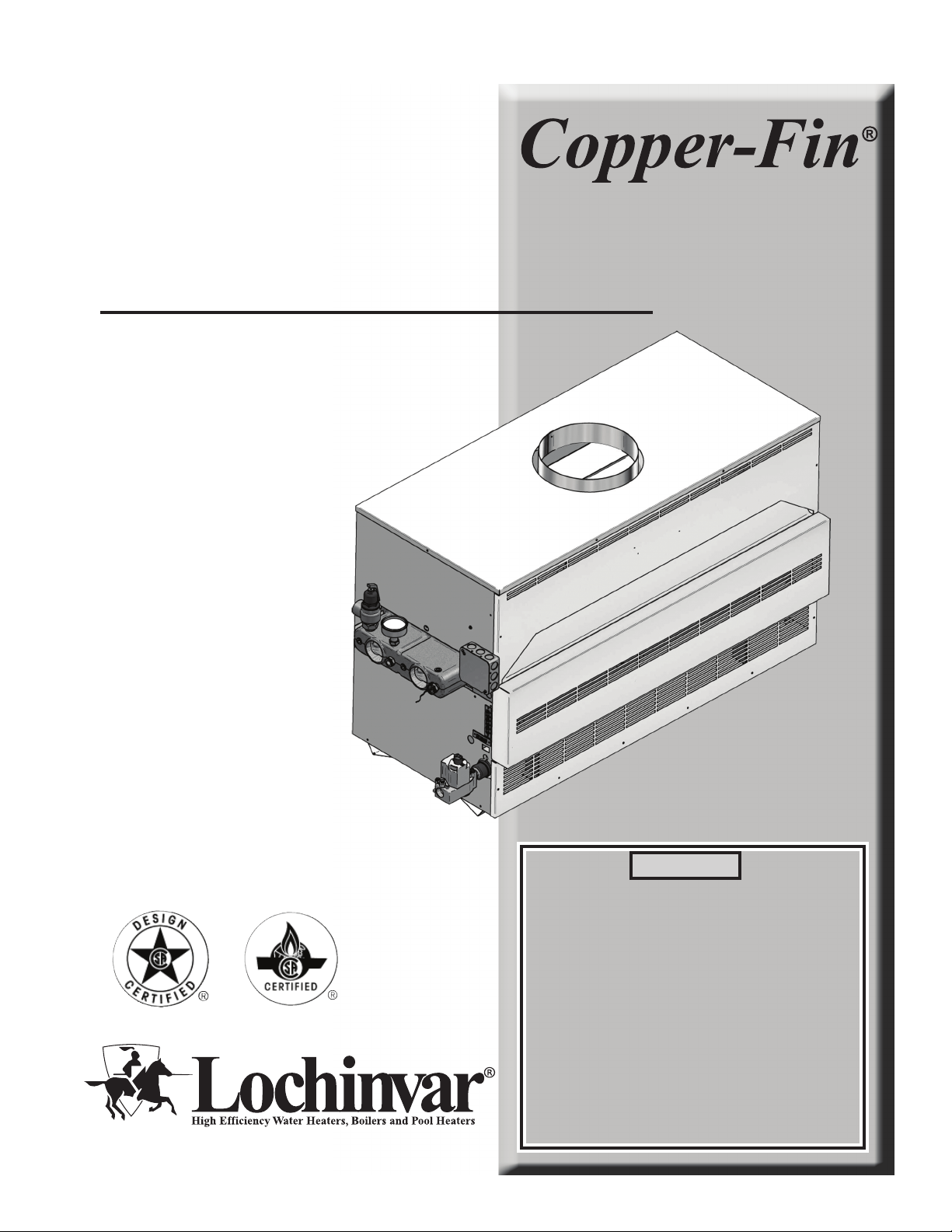
CFA-USER_100160873_2000001338_Rev D
User’s Information Manual
Models: 90,000 - 500,000 Btu/hr
WARNING:
If the information in this manual is not followed exactly, a fire or
explosion may result causing property damage, personal injury or
loss of life.
This appliance MUST NOT be installed in any location where
gasoline or flammable vapors are likely to be present.
WHAT TO DO IF YOU SMELL GAS
• Do not try to light any appliance.
• Do not touch any electric switch; do not use any phone in your
building.
• Immediately call your gas supplier from a near by phone.
Follow the gas supplier’s instructions.
• If you cannot reach your gas supplier, call the fire department.
• Installation and service must be performed by a qualified
installer, service agency, or the gas supplier.
Save this manual for future reference.
Page 2
Contents
HAZARD DEFINITIONS .................................................... 2
PLEASE READ BEFORE PROCEEDING ..................... 3-4
1. MAINTENANCE SCHEDULE ....................................... 5
Maintenance Procedures ................................................... 6
Appliance Must Be Serviced and Maintained .............. 6
Check Appliance Area .................................................. 6
Check Pressure Temperature Gauge ........................... 6
Check Vent Piping ........................................................ 6
Check Air Piping ........................................................... 6
Check Relief Valve ....................................................... 6
Test Low Water Cutoff (if installed) .............................. 6
Reset Button (low water cutoff) .................................... 6
Check Appliance Piping (gas and water) ..................... 7
Operate Relief Valve .................................................... 7
Shut Appliance Down ................................................... 7
2. OPERATING INSTRUCTIONS ................................ 8-11
Revision Notes .................................................. Back Cover
Hazard definitions
The following defined terms are used throughout this manual to bring attention to the presence of hazards of various risk levels or
to important information concerning the life of the product.
DANGER
WARNING
CAUTION
CAUTION
NOTICE
DANGER indicates an imminently hazardous situation which, if not avoided, will result in death or serious
injury.
WARNING indicates a potentially hazardous situation which, if not avoided, could result in death or serious
injury.
CAUTION indicates a potentially hazardous situation which, if not avoided, may result in minor or moderate
injury.
CAUTION used without the safety alert symbol indicates a potentially hazardous situation which, if not
avoided, may result in property damage.
NOTICE indicates special instructions on installation, operation, or maintenance that are important but not
related to personal injury or property damage.
2
Page 3
Please read before proceeding
User’s Information Manual
NOTICE
WARNING
This is a gas appliance and should be
installed by a licensed electrician and/or
certified gas supplier. Service must be
performed by a qualified service installer,
service agency or the gas supplier.
If the information in these instructions is
not followed exactly, a fire or explosion
may result causing property damage,
personal injury, or death.
This appliance MUST NOT be installed in
any location where gasoline or flammable
vapors are likely to be present, unless
the installation is such to eliminate the
probable ignition of gasoline or flammable
vapors.
What to do if you smell gas –
• Do not try to light any appliance.
• Do not touch any electric switch; do not use any
phone in your building.
• Immediately call your gas supplier from a near by phone.
Follow the gas supplier’s instructions.
• If you cannot reach your gas supplier, call the fire
department.
WARNING
Improper installation, adjustment, alteration,
service or maintenance can cause injury or
property damage. Refer to this manual for
assistance or additional information, consult
a qualified installer, service agency or the gas
supplier.
Checking equipment –
Upon receiving equipment, check for signs of shipping
damage. Pay particular attention to parts accompanying the
appliances which may show signs of being hit or otherwise
being mishandled. Verify total number of pieces shown on
the packing slip with those actually received. In case there is
damage or a shortage, immediately notify the carrier.
Do not use this appliance if any part has been under water.
The possible damage to a flooded appliance can be extensive
and present numerous safety hazards. Any appliance that has
been under water must be replaced.
Owner warning –
NOTE: Retain this manual for future reference.
The information contained in this manual is intended for use
by qualified professional installers, service technicians, or gas
suppliers. Consult your local expert for proper installation
or service procedures.
Installation and service must be performed by a qualified
installer, service agency, or the gas supplier.
Warranty –
Installation and service must be performed by a qualified
service installer, service agency or the gas supplier.
Factory warranty (shipped with unit) does not apply to units
improperly installed or improperly operated.
Experience has shown that improper installation or system
design, rather than faulty equipment, is the cause of most
operating problems.
1. Excessive water hardness causing a lime/scale build-up in
the copper tube is not the fault of the equipment and is
not covered under the manufacturer’s warranty (Refer to
the Water Treatment and Water Chemistry section in the
Copper-Fin Installation and Service manual).
2. Excessive pitting and erosion on the inside of the copper
tube may be caused by too much water velocity through
the tubes and is not covered by the manufacturer’s
warranty (Refer to Boiler Flow Rates and Temperature Rise
for flow requirements section in the Copper-Fin
Installation and Service manual).
IMPORTANT
Your conventionally vented gas appliance must have a supply
of fresh air circulating around it during burner operation for
proper gas combustion and proper venting.
WARNING
Consult and follow all local Building and
Fire Regulations and other Safety Codes
that apply to this installation. Consult your
local gas utility company to authorize and
inspect all gas and flue connections.
Should overheating occur or the gas supply
fail to shut off, do not turn off or disconnect
the electrical supply to the pump. Instead,
shut off the gas supply at a location external
to the appliance.
3
Page 4
Please read before proceeding
User’s Information Manual
WARNING
To minimize the possibility of serious
personal injury, fire, or damage to your
appliance, never violate the following safety
rules:
1. Boilers and water heaters are heat
producing appliances. To avoid damage
or injury, do not store materials against
the appliance or the vent-air intake
system. Use proper care to avoid
unnecessary contact (especially children)
with the appliance and vent-air intake
components.
2. Never cover your appliance, lean
anything against it, store trash or debris
near it, stand on it or in any way block
the flow of fresh air to your appliance.
3. UNDER NO CIRCUMSTANCES must
flammable materials such as gasoline or
paint thinner be used or stored in the
vicinity of this appliance, vent-air intake
system or any location from which fumes
could reach the appliance or vent-air
intake system.
Codes –
The equipment shall be installed in accordance with those
installation regulations in force in the local area where the
installation is to be made. These regulations shall be carefully
followed in all cases. Authorities having jurisdiction shall be
consulted before installations are made. In the absence of
such requirements, the installation shall conform to the latest
edition of the National Fuel Gas Code, ANSI Z223.1. Where
required by the authority having jurisdiction, the installation
must conform to American Society of Mechanical Engineers
Safety Code for Controls and Safety Devices for Automatically
Fired Boilers, ASME CSD-1. All boilers conform to the latest
edition of the ASME Boiler and Pressure Vessel Code, Section
IV. Where required by the authority having jurisdiction, the
installation must comply with the Canadian Association Code,
CAN/CGA- B149.1 and/or local codes.
This appliance meets the safe lighting performance criteria with
the gas manifold and control assembly provided as specified in
the ANSI standards for gas-fired appliances, ANSI Z21.13 and
ANSI Z21.10.3.
4
Page 5
1 Maintenance schedule
Service technician
(Refer to the Copper-Fin Installation and
Service manual)
General:
User’s Information Manual
Owner maintenance
• Check appliance area
• Address reported problems
• Inspect interior; clean and vacuum if
necessary;
• Check for leaks (water, gas, flue)
• Examine venting system
• Check system water pressure/
system piping/expansion tank
• Check fill water meter
• Test boiler water. When test
indicates, clean system water with
approved system restorer following
manufacturer’s information.
• Check control settings
• Check wiring connections
• Flame inspection (stable, uniform)
Annual Startup
• Check flue gas passageways
Daily
Monthly
Periodically
• Check pressure/temperature
gauge
• Check vent piping
• Check relief valve
• Remove debris from Y-strainer
per manufacturer’s instructions
• Check building recirculation
filter (if filter required)
• Test low water cutoff (if used)
• Reset button (low water cutoff)
• Inspect and clean the burner
• Perform start-up check-out and
performance verification. Refer to
the Startup section in the CopperFin Installation and Service manual
If combustion or performance
indicate need:
• Clean heat exchanger
• Remove and wash burner
Every
6 months
End
of season
months
• Check appliance piping (gas and
water) for leaks
• Operate relief valve
• Shut appliance down (unless
boiler used for domestic hot
water)
5
Page 6
1 Maintenance schedule
User’s Information Manual
Maintenance procedures
Appliance must be serviced and maintained
WARNING
WARNING
NOTICE
Check appliance area
WARNING
Follow the service and maintenance
procedures given throughout this manual
and in component literature shipped with
the appliance. Failure to perform the
service and maintenance could result
in damage to the appliance or system.
Failure to follow the directions in this
manual and component literature could
result in severe personal injury, death, or
substantial property damage.
The appliance must be inspected and
started annually at the beginning of the
heating season by a qualified service
technician. In addition, the maintenance
and care of the appliance designated on
page 5 of this manual and explained on
pages 6 through 7 must be performed to
assure maximum appliance efficiency and
reliability. Failure to service and maintain
the appliance and system could result in
equipment failure, causing possible severe
personal injury, death, or substantial
property damage.
The following information provides
detailed instructions for completing
the maintenance items listed in the
maintenance schedule on page 5. In
addition to this maintenance, the
appliance must be serviced and started up
at the beginning of each heating season by
a qualified service technician.
To prevent potential of severe personal
injury, death, or substantial property
damage, eliminate all materials discussed
below from the appliance vicinity and the
vicinity of the appliance combustion air
inlet. If contaminants are found:
Remove products immediately from the
area. If they have been there for an
extended period, call a qualified service
technician to inspect the appliance for
possible damage from acid corrosion.
1. Combustible/flammable materials -- Do not store
combustible materials, gasoline or any other flammable
vapors or liquids near the appliance. Remove
immediately if found.
2. Air contaminants -- Products containing chlorine or
fluorine, if allowed to contaminate the appliance intake
air, will cause acidic condensate in the boiler. This will
cause significant damage to the boiler if allowed to
continue.
WARNING
Failure to inspect the vent system as noted
above and have it repaired by a qualified
service technician can result in vent system
failure, causing severe personal injury or
death.
Check vent piping
1. Visually inspect the vent piping to be sure it is
unobstructed. Inspect the entire length of the vent
piping to ensure piping is intact and all joints are
properly sealed.
2. Call your qualified service technician if you notice any
problems.
Check relief valve
1. Inspect the appliance relief valve and the relief valve
discharge pipe for signs of weeping or leakage.
2. If the relief valve often weeps, the expansion tank may
not be working properly. Immediately contact your
qualified service technician to inspect the appliance and
system.
Test low water cutoff (if installed)
1. If the system is equipped with a low water cutoff, test the
low water cutoff periodically during the heating season,
following the low water cutoff manufacturer’s
instructions.
Reset button (low water cutoff)
1. Testing the low water cutoff shuts the unit off. Press the
RESET button on the low water cutoff to turn the unit
back on.
If products cannot be removed,
immediately call a qualified service
technician to re-pipe vent and air piping
and locate vent termination/air intake
away from contaminated areas.
6
Page 7
1 Maintenance schedule (continued)
User’s Information Manual
Check appliance piping (gas and water)
1. Access the appliance and perform a gas
leak inspection per steps 1 through 7 of the Operating
Instructions on page 8. If gas odor or leak is detected,
immediately shut down the boiler and call a qualified
service technician.
2. Visually inspect for leaks around water piping.
Also inspect the circulators, relief valve, and fittings.
Immediately call a qualified service technician to repair
any leaks.
WARNING
Have leaks fixed at once by a qualified
service technician. Failure to comply could
result in severe personal injury, death, or
substantial property damage.
Operate relief valve
1. Before proceeding, verify that the relief valve outlet has
been piped to a safe place of discharge, avoiding any
possibility of scalding from hot water.
WARNING
To avoid water damage or scalding due
to valve operation, a metal discharge line
must be connected to the relief valve
outlet and run to a safe place of disposal.
This discharge line must be installed by
a qualified heating installer or service
technician in accordance with the
instructions in the Copper-Fin Installation
and Service Manual. The discharge line
must be terminated so as to eliminate
possibility of severe burns or property
damage should the valve discharge.
Shut appliance down (unless boiler is
used for Domestic Water)
1. Follow “To Turn Off Gas to Appliance” on page 9 of this
manual.
2. Do not drain the system unless exposure to freezing
temperatures will occur.
3. Do not drain the system if it is filled with an antifreeze
solution.
4. DO NOT shut down boilers used for domestic water
heating, they must operate year-round.
2. Read the boiler pressure/temperature gauge to make
sure the system is pressurized. Lift the relief valve
top lever slightly, allowing water to relieve through
the valve and discharge piping.
3. If water flows freely, release the lever and allow the valve
to seat. Watch the end of the relief valve discharge pipe
to ensure that the valve does not weep after the line has
had time to drain. If the valve weeps, lift the seat again to
attempt to clean the valve seat. If the valve continues to
weep afterwards, contact your qualified service
technician to inspect the valve and system.
4. If water does not flow from the valve when you lift the
lever completely, the valve or discharge line may be
blocked. Immediately shut down the appliance. Call
your qualified service technician to inspect the appliance
and system.
7
Page 8
2 Operating instructions
User’s Information Manual
Lighting Instructions for Standing
Pilot Models (F1) Models 90,000
through 270,000 Btu/hr Input
FOR YOUR SAFETY READ BEFORE
OPERATING
WARNING
A. This appliance has a pilot which must be ig nit-
ed by hand. When lighting the pilot, follow these
instructions exactly.
B. BEFORE OPERATING, smell around the appliance
area for gas. Be sure to smell next to the floor because
some gas is heavier than air and will settle to the
floor.
WHAT TO DO IF YOU SMELL GAS
Do not try to light any appliance.
If you do not follow these instructions
exactly, a fire or explosion may result
causing property damage, personal injury
or loss of life.
Lighting Instructions
1. STOP! Read the safety information first.
2. Remove the control panel door.
3. Set the thermostat to the lowest setting (OFF).
4. Turn off all electrical power to the appliance.
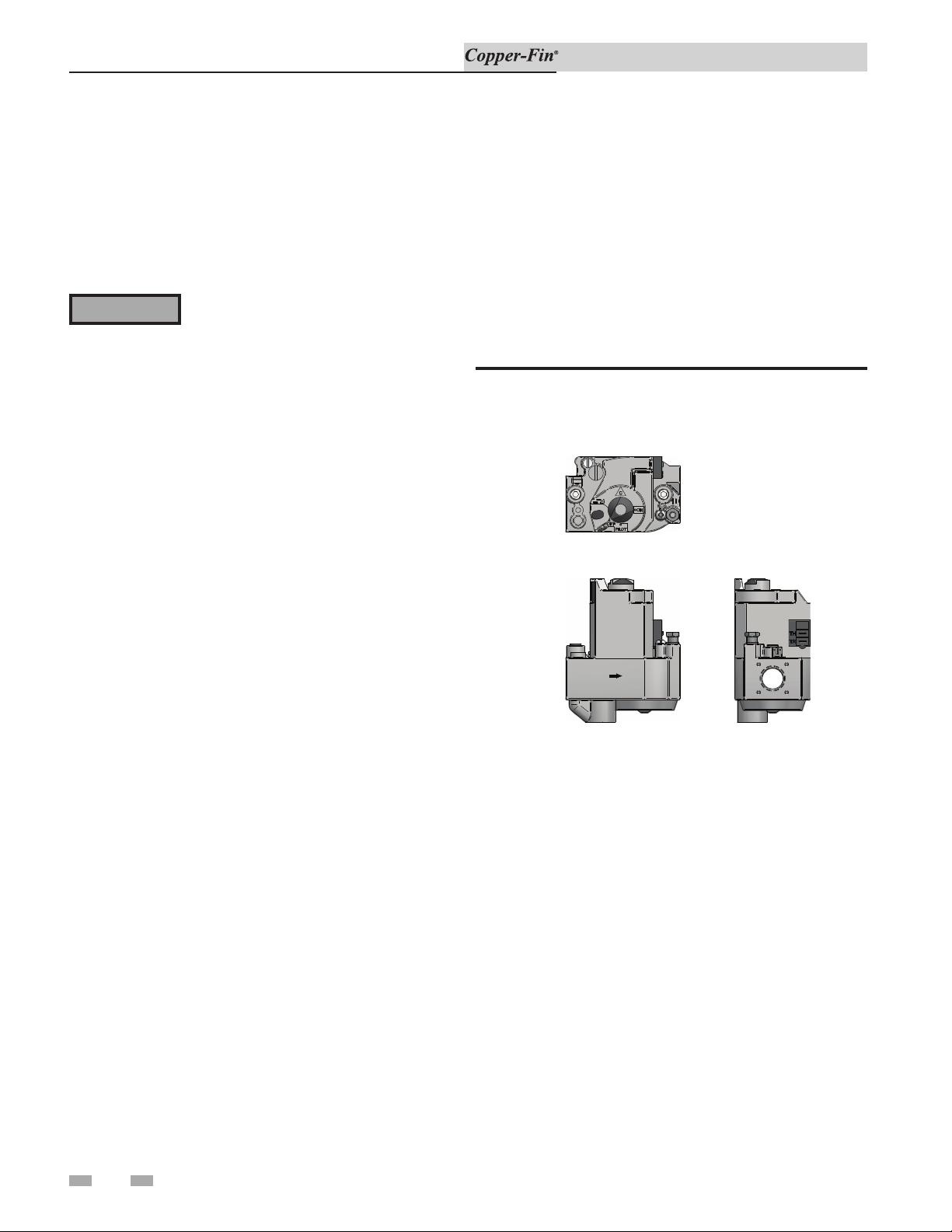
5. Turn the gas control knob on the gas valve clockwise to
the “OFF” position.
Figure 2-1_Gas Valve 90,000 - 270,000 Btu/hr Models
F-1 GAS VALVE
90,000 -270,000 BTU MODELS
TOP
Do not touch any electric switch; do not use any
phone in your building.
Immediately call your gas supplier from a near by
phone. Follow the gas supplier’s instructions.
If you cannot reach your gas supplier, call the fire
department.
C. Use only your hand to push in or turn the gas control
knob. Never use tools. If the knob will not turn by
hand, don’t try to repair it, call a qualified ser vice
technician. Force or attempted repair may result in a
fire or explosion.
D. Do not use this appliance if any part has been under
water. Immediately call a qualified service technician
to inspect the appliance. The pos si ble damage to
a flooded appliance can be extensive and present
numerous safety hazards. Any appliance that has
been under water must be replaced.
FLOW
SIDE
6. Wait five (5) minutes to clear out any gas, then smell for
gas, including near the floor. If you smell gas, STOP!
Follow the steps in the“What To Do If You Smell Gas”
section in the safety information. If you do not smell gas
go on to the next step.
7. Remove the lower panel door to gain access to the pilot.
8. Find the pilot - Follow the metal tube from the gas valve
to the pilot. The pilot is located on the right side of the
burner approximately centered in the burner tray.
OUTLET
8
Page 9
2 Operating instructions (continued)
User’s Information Manual
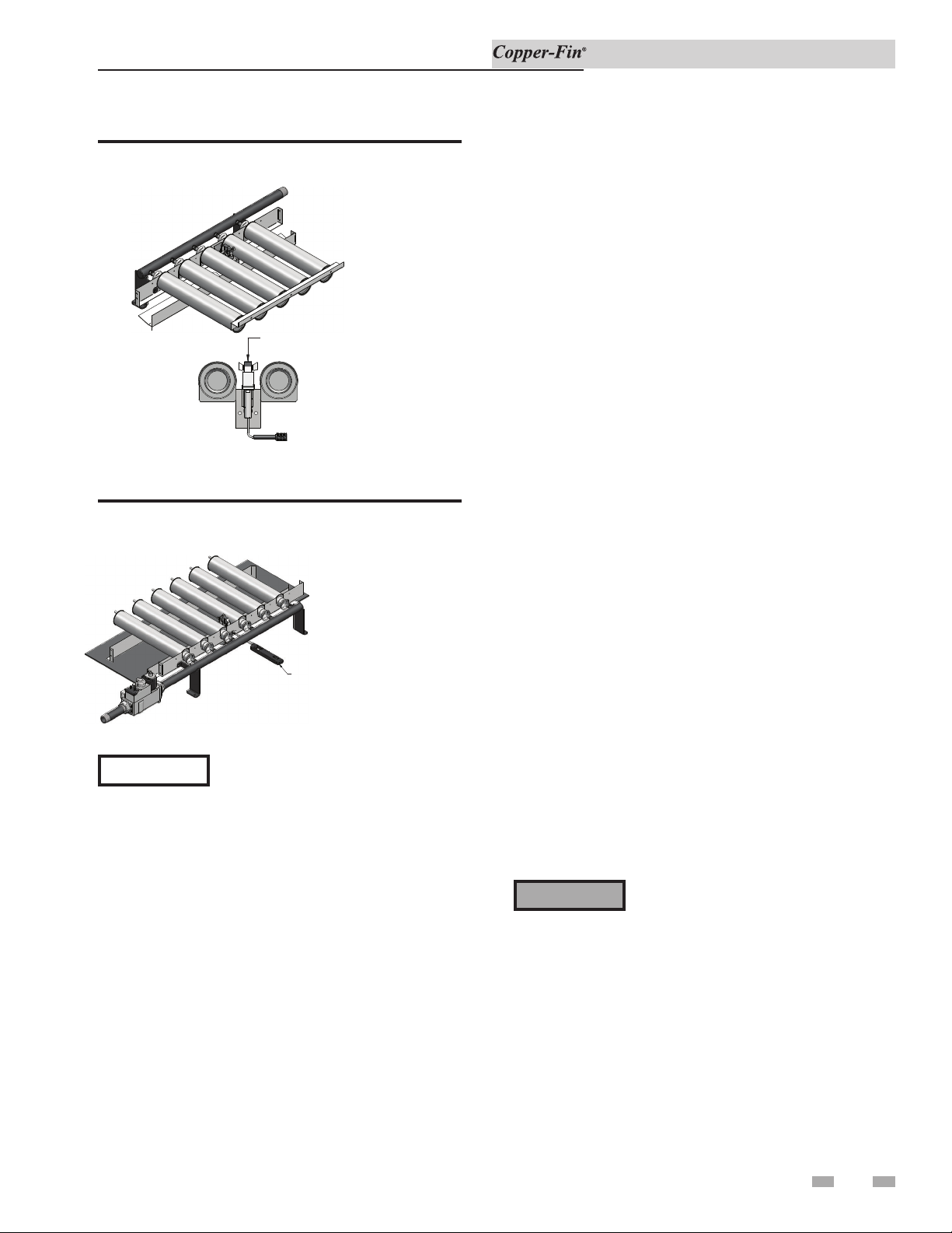
Figure 2-2_Pilot Location
Pilot Location
Main Burner
TOP OF FLAME SPREADER TO BE
FLUSH WITH TOP OF BURNER
9. Turn the control knob on the gas valve coun ter clock wise
to the “PILOT” position.
Figure 2-3_Lighting Wand
10. Use the loop end of the wire lighting wand, shipped
with the instruction pack age, to hold the match and
reach the pi lot. An access slot is provided in the lower
front jacket panel, beside the burner, to insert the
lighting wand and match to the pilot. Lift the pilot cover
(FIG. 2-3) to access the pilot. Push down and hold in
the red button on the gas valve. This should start gas
flow to the pilot. Con tin ue to hold the red button in for
about one (1) minute after the pilot is lit. Release the
button and it will pop back up. The pilot should remain
lit. If the pilot goes out, repeat steps 5 through 10.
If the red button does not pop up when re leased, stop
and immediately call your gas supplier.
If the pilot will not stay lit after sev er al tries, turn the gas
control to “OFF” and call your service technician or gas
supplier.
11. Turn the gas control knob on the gas valve
counterclockwise to the “ON” position.
12. Turn on all electric power to the appliance.
13. Re-install the lower panel door.
NOTICE
USE A FIELD SUPPLIED LIGHTER OR THE
FACTORY SUPPLIED LIGHTING WAND TO
LIGHT THE STANDING PILOT
The information package shipped
with the appliance contains a wire
lighting wand. The loop end of the
wand will hold a match. The wand
extends your reach to the pilot and
makes lighting the pilot easier (see
FIG. 2-3).
14. Set the thermostat to the desired setting.
15. Re-install the control panel door.
TO TURN OFF GAS TO APPLIANCE
1. Set the thermostat to the OFF position.
2. Turn off all electric power to the appliance if service is
to be performed.
3. Turn the gas control knob on the gas valve clockwise to
the “OFF” position. Do not force.
WARNING
Should overheating occur or the gas fail
to shut off, turn off the external manual
gas valve to the appliance.
9
Page 10
2 Operating instructions
User’s Information Manual
Safety Shutoff Test For Standing
Pilot Ignition System
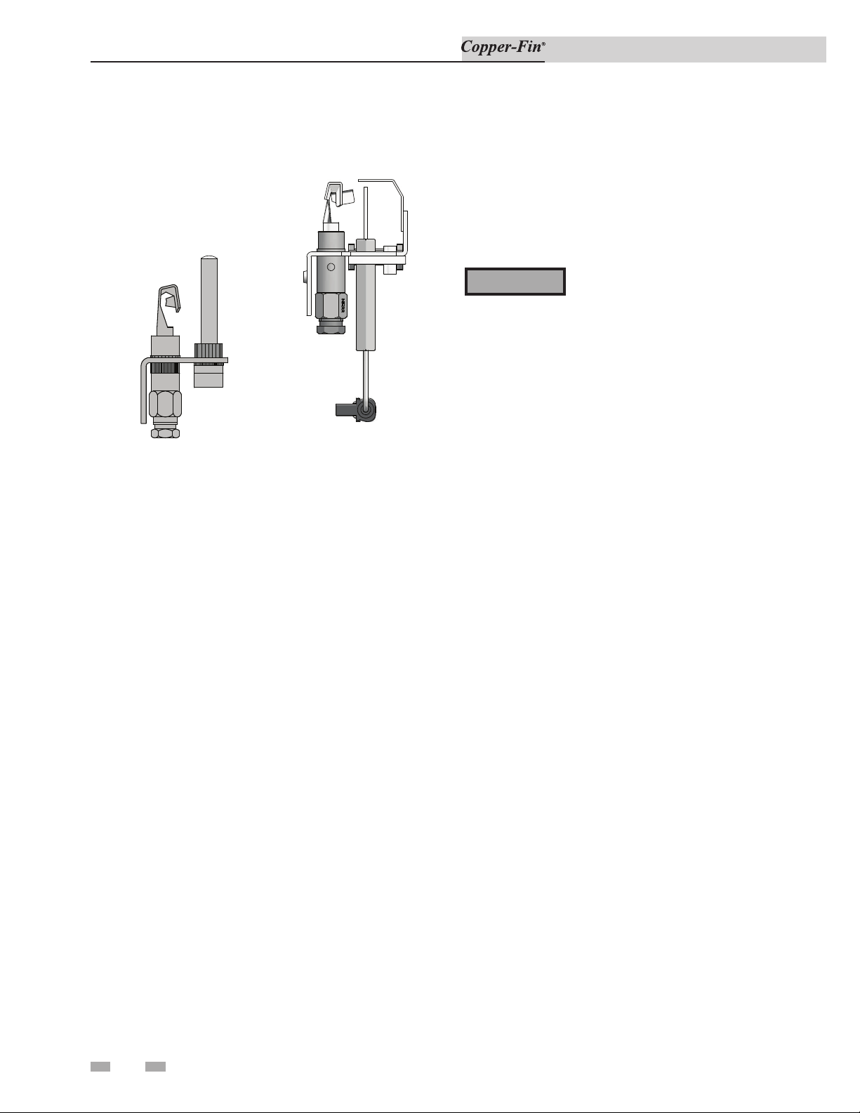
PILOT WITH THERMOCOUPLE
Figure 2-4_Pilot with Thermocouple and Spark Ignition
1. With the main burners on and firing, un screw the
thermocouple connection from the gas valve (FIG. 2-4)
and remove from the fitting.
PILOT WITH SPARK IGNITION
Lighting Instructions for Spark Ignition
Pilot Models (F9/M9) Models 90,000
through 500,000 Btu/hr Input
FOR YOUR SAFETY READ BEFORE
OPERATING
WARNING
A. This appliance is equipped with an ignition device
which automatically lights the pilot. Do not try to
light the pilot by hand.
B. BEFORE OPERATING, smell around the appliance
area for gas. Be sure to smell next to the floor
because some gas is heavier than air and will settle
to the floor.
WHAT TO DO IF YOU SMELL GAS
Do not try to light any appliance.
If you do not follow these instructions
exactly, a fire or explosion may result
causing property damage, personal
injury or loss of life.
2. The main gas valve should extinguish the burn ers
immediately after removal of the thermocouple.
3. If burners do not extinguish, immediately fol low steps in
“To Turn Off Gas To Appliance”.
4. Immediately call a qualified serviceman or in stall er to
repair an ignition system that fails to op er ate properly and
shut down the burners.
5. After successful completion of test, turn the control knob
on the gas valve clockwise to the “OFF” position. Do not
force.
6. Carefully reconnect the thermocouple to the gas valve.
7. Follow the Lighting Instructions to relight the pilot and
establish normal operation.
Do not touch any electric switch; do not use any
phone in your building.
Immediately call your gas supplier from a nearby
phone. Follow the gas supplier’s instructions.
If you cannot reach your gas supplier, call the fire
department.
C. Use only your hand to turn the gas control knob.
Never use tools. If the knob will not turn by
hand, don’t try to repair it, call a qualified ser vice
technician. Force or attempted repair may result in
a fire or explosion.
D. Do not use this appliance if any part has been
under water. Immediately call a qualified service
technician to inspect the appliance. The pos si ble
damage to a flooded appliance can be extensive and
present numerous safety hazards. Any appliance
that has been under water must be replaced.
10
Page 11
2 Operating instructions
User’s Information Manual
Operating Instructions
1. STOP! Read the safety information first.
2. Remove the control panel door.
3. Set the thermostat to the lowest setting (OFF).
4. Turn off all electrical power to the appliance.
5. This appliance is equipped with an ignition device which
automatically lights the pilot. DO NOT try to light the
pilot by hand.
6a. 90,000 - 135,000 and 399,999 - 500,000 Btu/hr models,
rotate the gas control knob on the gas valve clockwise to
the “OFF” position.
6b. 180,000 - 360,000 Btu/hr models, rotate the gas control
knob on the gas valve clockwise to the line on the collar
around the knob. Depress the knob and continue rotation
to the “OFF” position.
7. Wait five (5) minutes to clear out any gas, then smell for
gas, including near the floor. If you smell gas, STOP!
Follow the steps in the “What To Do If You Smell Gas”
section in the safety information, this page. If you do not
smell gas go on to the next step.
8a. 90,000 - 135,000 and 399,999 - 500,000 Btu/hr
models, rotate the gas control knob on the gas valve
counterclockwise to the “ON” position.
8b. 180,000 - 360,000 Btu/hr models, rotate the gas control
knob on the gas valve counterclockwise to the line on the
collar around the knob. Al low the knob to “pop” up, and
continue rotation to the “ON” position.
9. Turn on all electric power to the appliance.
10. Set the thermostat to the desired setting.
11. Re-install the control panel door.
12. If the appliance will not operate, follow the instructions
“To Turn Off Gas To Appliance” and call your service
technician or gas supplier.
3a. 90,000 - 135,000 and 399,999 - 500,000 Btu/hr models,
rotate the gas control knob on the gas valve clockwise to
the “OFF” position. Do not force.
3b. 180,000 - 360,000 Btu/hr models, rotate the gas control
knob on the gas valve clockwise to the line on the
collar around the knob. Depress the knob and continue
rotation to the “OFF” position. Do not force.
WARNING
Should overheating occur or the gas fail to
shut off, turn off the external manual gas
valve to the appliance.
Safety Shutoff Test for Spark
Ignition Pilot System
1. Turn “OFF” gas supply to the appliance.
2. Turn thermostat to highest setting.
3. Turn electric power “ON”.
4. Pump relay pulls in to start pump.
5. The ignition will begin sparking at the pilot.
6. The ignition module will lock out after the trial for
ignition period.
7. Immediately call a qualified serviceman or in stall er
to repair an ignition system that fails to lock out and
properly shut down burner operation.
8. After successful completion of the test, re ad just the
thermostat to normal setting.
9. Turn “ON” gas supply.
10. Turn power “OFF” then “ON” to reset ignition module.
11. If ignition system fails to operate properly, re pair work
must be performed by a qualified serviceman or installer.
Intermittent Pilot Spark Ignition
System
To Turn Off Gas to Appliance
1. Set the thermostat to the OFF position.
2. Turn off all electric power to the appliance if service is to
be performed.
WARNING
The ignition module is not repairable.
Any mod i fi ca tion or repairs will invalidate
the warranty and may create hazardous
conditions that result in prop er ty damage,
personal injury, fire, explosion and/or
toxic gases. A faulty ignition module must
be re placed with a new module.
11
Page 12

Revision Notes: Revision A (ECO C06290) initial release.
Revision B (ECO C12077) reflects the update of ignition
timing information on page 11.
Revision C (PCP #3000021634 / CN #500011858)
reflects an update to the chart on page 5.
Revision D (PCP #3000030852 / CN #500020656)
reflects an update to the owner maintenance schedule.
CFA-USER_MM #100160873_DIR #2000001338_Rev D
04/19
 Loading...