

Page 1
Boiler
Product Line
Brochure
Page 2
Lochinvar Corporation
300 Maddox Simpson Pkwy
Lebanon, TN 37090
615-889-8900 / Fax: 615-547-1000
www.Lochinvar.com
Page 3
From the SolutionTM to the SYNC®, Lochinvar Boilers are noted for their
range of benefits and application flexibility. Collectively, they represent the most
complete product line in the industry. From a company with a long history of
innovation and a reputation for excellence.
You’ll find there’s a Lochinvar product for any application imaginable – from
standard residential units to the advanced Intelli-Fin
®
. And with selection, comes
opportunity.
In fact, the diversity and performance of our product line is surpassed only by
it’s quality–in design, construction, and training. A commitment that is reinforced
by the Lochinvar Tech Center, a state-of-the-art testing and training facility
equipped with the very latest in CAD/CAM technology and a comprehensive
R&D lab.
Quality, efficiency, features, service, and selection. For more than 90 years,
these have been the hallmarks of Lochinvar products.
Contents
CREST 1
SYNC® 3
Power-Fin
KNIGHT XL 7
Copper-Fin II
Copper-Fin
Copper-Fin
®
5
®
9
®
11
®
Atmospheric 13
Lochinvar...the innovator in boiler technology.
This emblem means a product has a NOx
rating which exceeds the requirements of
the South Coast Air Quality Management
District and Texas Commission of
Environmental Quality.
This emblem means the Stack Frame is
available for use with that product. See page
27 for details.
This catalog is designed to provide a convenient, condensed overview of the entire Lochinvar boiler product
line. For a complete list of features, specifications and technical data on a particular product, see the full line
catalog, your local distributor or contact Lochinvar. Every Lochinvar product is designed and built to meet
or exceed the fuel efficiency and safety standards of one or more of these agencies, wherever applicable.
KNIGHTTM 15
Efficiency+
Solution
®
19
TM
21
Buffer Tanks 23
Squire Buffer Tank 24
Squire Stainless Steel 25
Stack Frame 27
Low Temperature Valve 29
Electric Boilers 30
Page 4
99
CREST allows system designers tremendous flexibility to vary the flow rate through the boiler. It can service systems that operate
with widely fluctuating flow rates depending on demand. CREST can be installed with primary/secondary piping or in a full-flow
arrangement. Typical design techniques include full-flow systems or variable flow systems using variable frequency drives on the
heating water pumps. In either case, CREST excels in these applications and allows the flow through the boiler to vary based on
system demand. * 35 GPM min. flow on FB1500 model, 80 GPM on FB3500 model.
Sequences up to an 8-boiler system using simple 2-wire daisy-chain
connection, eliminating cost and uncertainty of separate “third party”
sequencer. On demand, one boiler functions as the leader and modulates
to capacity. Increasing load then “cascades” to additional “lag” boilers
in sequence as needed. Lead-lag rotation shifts “first on” boiler role
every 24 hours, distributing equal lead-lag runtimes to each unit.
CREST’s ability to sequence up to eight units that each have as much
as 25:1 turndown means that the combined system has the potential of
operating with modulation of up to 200:1 turndown. A bank of eight
2.0M Btu CRESTs would be able to provide as little as 80,000 Btu/hr and as much as 16,000,000 Btu/hr of heating output. In addition,
the CREST Cascade can be set for “Efficiency Optimization” with each boiler firing at the same low BTU/hr input rates to receive
the benefits of the highest thermal efficiency.
CR
CR
asas(N(Nsy
s
sy
s
pr
e
pr
e
con
con
for
for
u
25
25
a 2
a 2
dem
demdede
sys
sys
ret
retofof
Fire Tube Innovation up to 3.5 Million BTU
Lochinvar® has taken the fire-tube concept in an innovative new direction with the
CREST® modulating-condensing boiler. With sizes that range from 1.5 to 3.5 million
Btu/hr, you finally have the opportunity to utilize Lochinvar leading-edge technology
in your largest applications. W ith thermal efficiencies up to 99% in low water temperature
applications, CREST is positioned to provide exceptional energy-saving performance.
The advanced CREST introduces a combustion system with a unique burner design with
up to 25:1 turndown. The burner fires into an array of 316L stainless steel fire-tubes that
transfer the heat to the surrounding water with exceptionally high efficiency.
CREST communicates seamlessly and in real time with building management systems
by utilizing an on-board Modbus protocol. The SMART TOUCH™ control has a builtin cascading feature that communicates with up to eight units, providing total command
without an external control or complex and expensive control logic programming by the
BMS integrator.
Yes, innovative fire-tube boiler technology integrated with our SMART TOUCH™
operating control makes the CREST a genuine game-changer among commercial boilers.
Advanced Negative Regulation Technology
CREST safely and reliably operates with supply gas pressure
as low as 4 inches water column. Because Negative Regulation
(Neg/Reg) technology draws fuel gas into a pre-mix combustion
system instead of relying on utility pressure through the gas valve, operation is steady in low gas
pressure systems or when peak demands occur on supply lines. Plus, Neg/Reg automatic fan speed
control fine-tunes the correct fuel/air ratio entering the burner, providing even, consistent combustion
for a cleaner burning flame achieving high combustion efficiency.
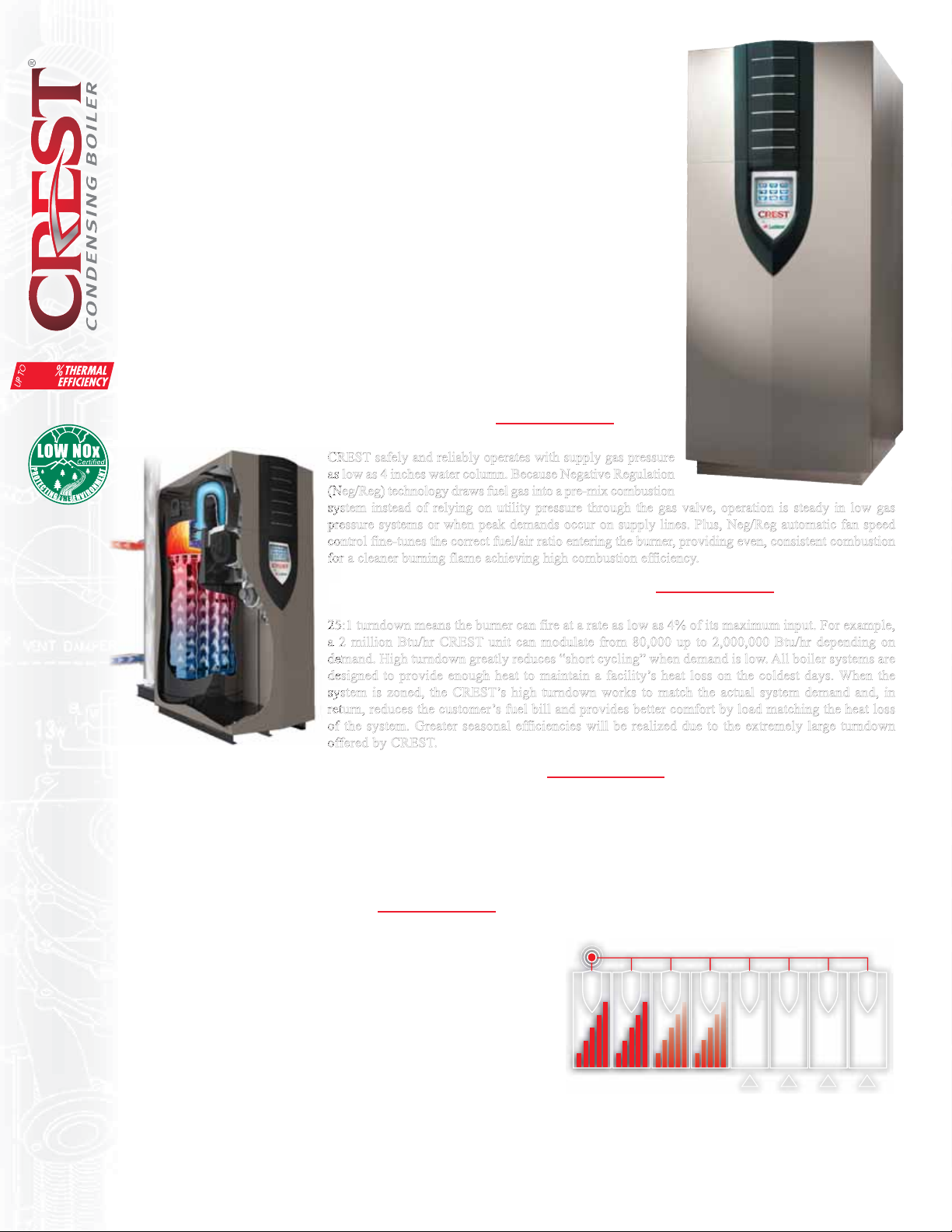
Fully Modulating up to 25:1 Turndown
F
25:1 turndown means the burner can fire at a rate as low as 4% of its maximum input. For example,
a 2 million Btu/hr CREST unit can modulate from 80,000 up to 2,000,000 Btu/hr depending on
demand. High turndown greatly reduces “short cycling” when demand is low. All boiler systems are
designed to provide enough heat to maintain a facility’s heat loss on the coldest days. When the
system is zoned, the CREST’s high turndown works to match the actual system demand and, in
return, reduces the customer’s fuel bill and provides better comfort by load matching the heat loss
of the system. Greater seasonal efficiencies will be realized due to the extremely large turndown
offered by CREST.
As Low As 35 GPM* to Full 350 GPM Flow Rates
CREST allows system designers tremendous flexibility to vary the flow rate through the boiler. It can service systems that operate
with widely fluctuating flow rates depending on demand. CREST can be installed with primary/secondary piping or in a full-flow
arrangement. Typical design techniques include full-flow systems or variable flow systems using variable frequency drives on the
heating water pumps. In either case, CREST excels in these applications and allows the flow through the boiler to vary based on
system demand. * 35 GPM min. flow on FB1500 model, 80 GPM on FB3500 model.
Built-in Cascading Sequencer
Sequences up to an 8-boiler system using simple 2-wire daisy-chain
connection, eliminating cost and uncertainty of separate “third party”
sequencer. On demand, one boiler functions as the leader and modulates
to capacity. Increasing load then “cascades” to additional “lag” boilers
in sequence as needed. Lead-lag rotation shifts “first on” boiler role
every 24 hours, distributing equal lead-lag runtimes to each unit.
CREST’s ability to sequence up to eight units that each have as much
as 25:1 turndown means that the combined system has the potential of
operating with modulation of up to 200:1 turndown. A bank of eight
2.0M Btu CRESTs would be able to provide as little as 80,000 Btu/hr and as much as 16,000,000 Btu/hr of heating output. In addition,
the CREST Cascade can be set for “Efficiency Optimization” with each boiler firing at the same low BTU/hr input rates to receive
the benefits of the highest thermal efficiency.
1
Page 5
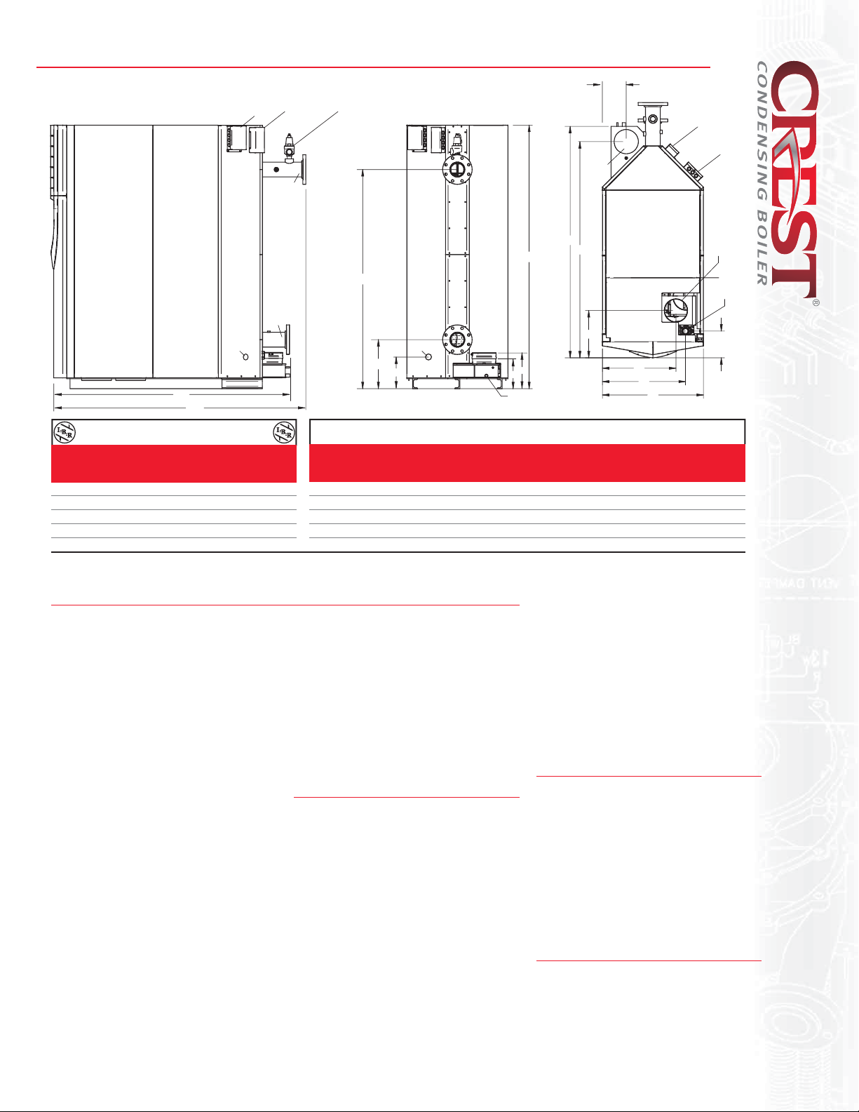
CREST® Boiler Dimensions & Specifications
H
HIGH
VOLTAGE
DRAIN
J
K
WATER
OUTLET
WATER
INLET
LOW
VOLTAGE
Crest Heating Boiler Dimensions and Specifications
Model Input Input NET
Number MBH MBH Thermal Output I=B=R Turndown
Min. Max. Efficiency MBH MBH
FBN1500 60 1,500 92.0% 1,380 1,200 25:1
FBN2000 80 2,000 92.0% 1,840 1,600 25:1
FBN2500 125 2,500 92.0% 2,300 2,000 20:1
FBN3000 150 3,000 92.0% 2,760 2,400 20:1
FBN3500 200 3,500 92.0% 3,220 2,800 18:1
Notes: Indoor installation only. All information subject to change. Change "N" to "L" for LP gas models. Low NOx on FB2500 - FB3500 models, consult factory.
*Turndown rate reduced on LP gas models.
*
Smart Touch™ Features
• SMART TOUCH™ Touchscreen Operating Control
• Full-Color 8” Touchscreen LCD Display
• Built-in Cascading Sequencer for up to 8 Boilers
• Building Management System Integration with
0-10 VDC Input
• Modbus Communications
• Outdoor Reset Control with Outdoor Air Sensor
• Password Security
• Domestic Hot Water Prioritization
• Low Water Flow Safety Control & Indication
• Inlet & Outlet Temperature Readout
• Freeze Protection
•
Service Reminder
• Time Clock
• Data Logging
• Hours Running, Space Heating
• Hours Running, Domestic Hot Water
• Ignition Attempts
• Last 10 Lockouts
• Programmable System Efficiency Optimizers
• Night Setback
• Anti-Cycling
•
Outdoor Air Reset Curve
• Ramp Delay
• Boost Temperature & Time
• Three Pump Control
• System Pump
• Boiler Pump
• Domestic Hot Water Pump
• High-Voltage Terminal Strip
• 120 VAC / 60 Hertz / 1 Phase Power Supply
• System and Boiler Pump Contacts
• Low-Voltage Terminal Strip
• 24 VAC Auxiliary Device Relay
• Auxiliary Proving Switch Contacts
• Alarm on Any Failure Contacts
• Runtime Contacts
• Unit Enable/Disable Contacts
• System Sensor Contacts
• DHW Tank Sensor Contacts
• Outdoor Air Sensor Contacts
• Cascade Contacts
• 0-10 VDC BMS External Control Contact
Standard Features
• 92% Thermal Efficiency (AHRI)
• Up to 99% Thermal Efficiency in Low
• Modulating Burner with up to 25:1
• Low-NOx Operation
• Sealed Combustion
• Vertical or Horizontal Venting
• Category IV Venting up to 100 Feet
• ASME “H” Stamped Heat Exchanger
• 316L Stainless Steel Fire Tubes
• 160 psi Working Pressure
• Adjustable High Limit with Manual Reset
• Low Water Cutoff with Manual Reset & Test
• High & Low Gas Pressure Switches w/
• Low Air Pressure Switches
RELIEF
VALVE
4" FLG
OUTLET
80"
66-5/8"
4" FLG
DRAIN
14-7/8"
10 -1/4"
Gas Air Vent Operating Shipping
A B C D E F G H Conn. Inlet Size Wt. (lbs.) Wt. (lbs.)
INLET
11"
8"
CONDENSATE
DRAIN
VENT
B
C
D
E
G
A
30-3/4" 71-1/2" 65-3/4" 14-3/8" 22-3/8" 8-1/2" 25-1/4" 8-1/8" 1-1/2" 7" 7" 2,496 1,900
30-3/4" 71-1/8" 65-1/8" 14-7/8" 22-3/8" 8-1/4" 25-3/8" 9-5/8" 1-1/2" 8" 8" 3,054 2,150
34-1/4" 76-3/8" 70-1/4" 17-3/4" 26-1/8" 9-3/4" 27-3/8" 11-3/8" 2" 8" 9" 3,652 2,560
40-1/2" 83-5/8" 76-3/8" 17-3/8" 31-3/8" 9-7/8" 34-3/4" 11-1/2" 2" 10" 10" 4,126 2,920
40-1/2" 83-1/4" 75-5/8" 17-1/4" 31-3/8" 9-7/8" 34-3/4" 12-7/8" 2" 10" 10" 4,744 3,225
• System Sensor Outdoor Air Sensor
• Inlet & Outlet Temperature Sensors
•
High Voltage Terminal Strip
• Low Voltage Terminal Strip
• Downstream Gas Test Cocks
• 50 psi ASME Relief Valve
•
DHW Thermostat Contacts
• Temperature & Pressure Gauge
•
Zero Clearances to Combustible Materials
• 10-Year Limited Warranty
(See Warranty for Details)
• 1-Year Warranty on Parts
(See Warranty for Details)
Optional Equipment
• Alarm Bell
• BMS Gateway - BACnet or LonWorks
• Condensate Neutralization Kit
•
•
Temperature Applications
Turndown
•
Direct-Spark Ignition
SMART TOUCH PC Software
• Common Vent Kits
• Vent Termination Kits
• Dual Fuel Gas Train - Consult factory
• Electrical Options:
208V/3Ø/60Hz
•
Low Gas Pressure Operation
240V/1Ø/50Hz
480V/3Ø/60Hz
600V/3Ø/60Hz
Codes & Registrations
• ANSI Z21.13/CSA Certified
•
•
On/Off Switch
Manual Reset
ASME certified, “H” Stamp / National Board
• California Code Compliant
• CSD1 / Factory Mutual / GE Gap Compliant
• South Coast Air Quality Management
District Qualified
• Canadian Registration Number (CRN)
•
AHRI Certified
LOW
VOLTAGE
HIGH
VOLTAGE
AIR
GAS
F
2
Page 6
Building on a Tradition of Innovation
s t
.
Lochinvar’s commitment to research and development once again brings
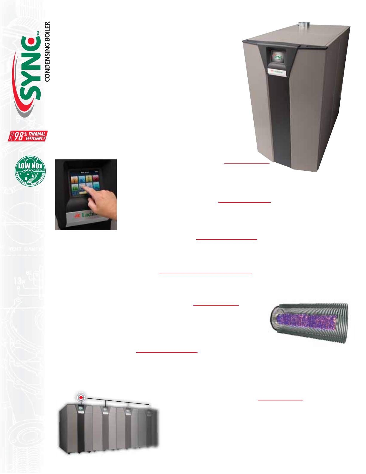
innovation to the industry! The SYNC™ Commercial Boiler combines stainless
steel heat exchanger technology with Modulating Condensing combustion to
deliver thermal efficiencies as high as 98% in low-temperature applications.
With models at 1.0, 1.3 and 1.5 million BTU/hr inputs, SYNC will serve a
large range of commercial applications and add the “green” touch that building
owners and facility managers desire.
SYNC also reaches new levels of innovation with SMART TOUCH™…
touchscreen technology that puts total operational control at your fingertips!
With SMART TOUCH, it’s easier than ever to set up a perfectly synchronized
“green” system, and access a complete onboard database of real-time operational
data and performance history.
Other features in SYNC include space-saving footprints, direct-vent design with
intake and exhaust runs up to 100 feet, and a built-in cascading sequencer for up
to 8 boilers, delivering up to 12 million BTU/hr heating capacity.
Total Control, at Your Fingertips
The full-color SMART TOUCH Main Menu screen is your gateway to
complete control of all SYNC functions, and total access to system performance data and
history. Do it all and see it all right here, using our SMART TOUCH software.
Direct-Venting up to 100 Feet
SYNC offers tremendous flexibility for building plan placement because it permits direct-vent air intake
and exhaust runs up to 100 equivalent feet using PVC, CPVC or AL29-4C stainless steel vent pipe. Intake
and exhaust runs can terminate horizontally through a sidewall or vertically through the roof
Advanced Negative Regulation Technology
SYNC safely and reliably operates with supply gas pressure as low as 4 inches water column, because Negative Regulation (Neg/Reg)
technology automatically adjusts fan speed to ensure the correct volume of fuel and air entering the burner.
“Fail-Safe” Direct-Spark Ignition
With each call for heat, two electrodes ignite the fuel/gas mixture. A third electrode then senses for flame. SMART TOUCH will lock
out and display the fault if ignition does not occur.
Two-in-One Stainless Steel Heat Exchanger
A primary heat exchanger combined with a secondary exchanger captures flue gas heat and allows
very low return water temperatures and does not require a low-temperature bypass. The stainless
steel, pH-tolerant design features a weld-sealed assembly with no O-rings or gaskets, and does not
require special glycol. ASME Section IV approved and stamped.
Fully Modulating Burner
SMART TOUCH allows fully modulating combustion with 10:1 turndown. The combustion system can operate as low as 10% of
maximum input, and modulates the firing rate up to 100% as demand increases. The burner design incorporates a woven steel mesh
sleeve over a stainless steel burner tube and fires in a 360° pattern along the entire length of the primary heat exchanger. These together
allow SYNC’s compact size to excel compared to units with larger multiple burners.
Built-in Cascading Sequencer
Sequences up to an 8-boiler system using simple 2-wire daisy-chain connection,
eliminating cost and uncertainty of separate “third party” sequencer. On demand,
one boiler functions as the “leader”, and modulates to capacity. Increasing load
then “cascades” to additional “lag” boilers in sequence as needed. Lead-lag
rotation shifts “first on” boiler role every 24 hours, distributing equal lead-lag
runtimes to each unit.
3
Page 7
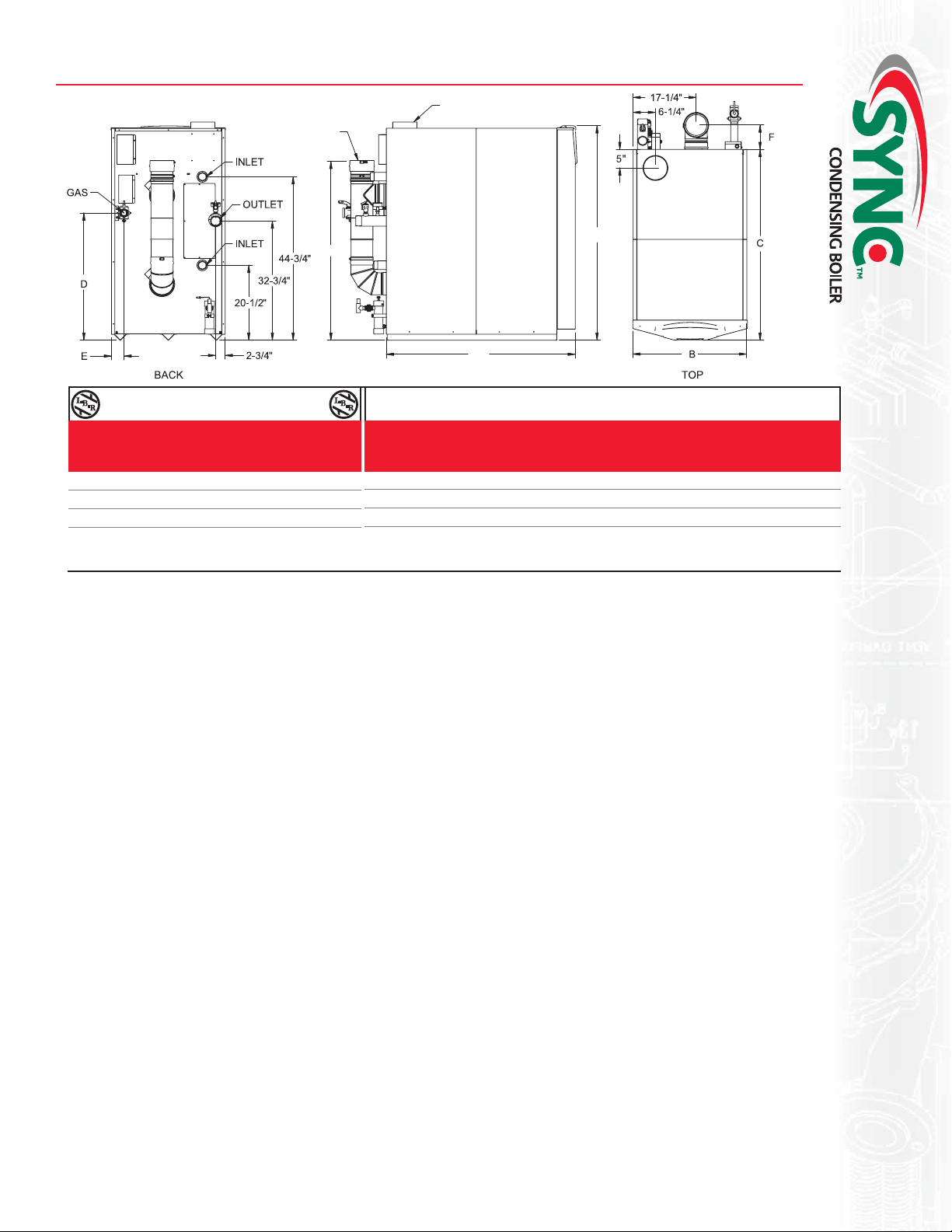
SYNCTM Boiler Dimensions & Specifications
FLUE
AIR INTAKE
49"
C
LEFT
Sync Heating Boiler
Input Net
Model Min. Max. Thermal Output I=B=R
Number MBH MBH Efficiency MBH MBH
SBN1000 100 1,000 94.1% 941 818
SBN1300 130 1,300 95.4% 1,240 1,078
SBN1500 150 1,500 96.2% 1,443 1,255
Notes: Change ‘N’ to ‘L’ for L.P. Gas Model. No deration on L.P. models. Performance data based on manufacturer test results. 120 VAC /15 AMP circuit required.
All dimensions shown in inches.
Standard Features
• Up to 96.2% Thermal Efficiency
• Modulating Burner with 10:1 Turndown
• Direct-Spark Ignition
• Low NOx Operation
• Sealed Combustion
• Low Gas Pressure Operation
• Vertical & Horizontal Venting
• Category IV Venting up to 100 Feet
• PVC, CPVC or AL29-4C Vent Material
• Sidewall Vent Terminations Provided
• ASME Stainless Steel Heat Exchanger
• ASME Certified, “H” Stamped
• Gasketless Design
• 160 psi Working Pressure
• On/Off Switch
• Adjustable High Limit with Manual Reset
• Low Water Cutoff with Manual Reset & Test
• Low Air Pressure Switch
• High & Low Gas Pressure Switches
with Manual Reset
• Inlet & Outlet Temperature Sensors
• Two Easy Access Terminal Strips
• Downstream Test Cocks
• 50 psi ASME Relief Valve
• Temperature & Pressure Gauge
• Zero Clearance to Combustible Material
• Approved for Combustible Floor Installation
• 1 Year Warranty on Parts
• 10 Year Limited Warranty
(see warranties for details)
Inlet Outlet
Gas Water Water Air Vent Shipping
A B C D E F Conn. Conn. Conn. Inlet Size Wt. (lbs.)
58-3/4" 31" 48" 35" 4-1/2" 15" 1-1/2" 2" x 2" 3" 6" 6" 786
58-3/4" 31" 52-1/4" 34-3/4" 3-1/2" 6-3/4" 1-1/2" 2" x 2" 3" 6" 6" 856
58-3/4" 31" 56-1/2" 34-3/4" 3-1/2" 6-3/4" 1-1/2" 2" x 2" 3" 6" 6" 926
SMART TOUCH™ Features
• SMART TOUCH™ Touchscreen Operating Control
• Full-Color Touchscreen LCD Display
• Built-in Cascading Sequencer for up to 8 Boilers
• Building Management System Integration with
0-10 VDC Input
• Outdoor Reset Control with Outdoor Air Sensor
• Dual Level Password Security
• Domestic Hot Water Prioritization
• Low Water Flow Safety Control & Indication
• Inlet & Outlet Temperature Readout
• Freeze Protection
• Service Reminder
• Time Clock
• Data Logging
• Hours Running, Space Heating
• Hours Running, Domestic Hot Water
• Ignition Attempts
• Last 10 Lockouts
• Programmable System Efficiency Optimizers
• Night Setback
• Anti-Cycling
• Outdoor Air Reset Curve
• Boost Temperature & Time
• Three Pump Control
• System Pump
• Boiler Pump
• Domestic Hot Water Pump
Dimensions and Specifications
A
• High Voltage Terminal Strip
• 120 VAC / 60 Hertz / 1-Phase
Power Supply
• Three Sets of Pump Contacts
• Low Voltage Terminal Strip
• 24 VAC Auxiliary Device Relay
• Auxiliary Proving Switch Contacts
• Flow Switch Contacts
• Alarm on Any Failure Contacts
• Runtime Contacts
• DHW Thermostat Contacts
• Unit Enable/Disable Contacts
• System Sensor Contacts
• DHW Tank Sensor Contacts
• Outdoor Air Sensor Contacts
• Cascade Contacts
Optional Equipment
• Alarm Bell
• Condensate Neutralization Kit
• SMART SYSTEM PC Software
• Modbus Communications
• Stainless Steel Vent Kits
Codes & Registrations
• ANSI Z21.13a-2010 certified
• ASME certified, “H” stamp
• California Code compliant
• CSD1 / FM / GE Gap
• Massachusetts Code compliant
• South Coast Air Quality Management
District registered
Registered under U.S. Patent # 7,506,617
4
Page 8
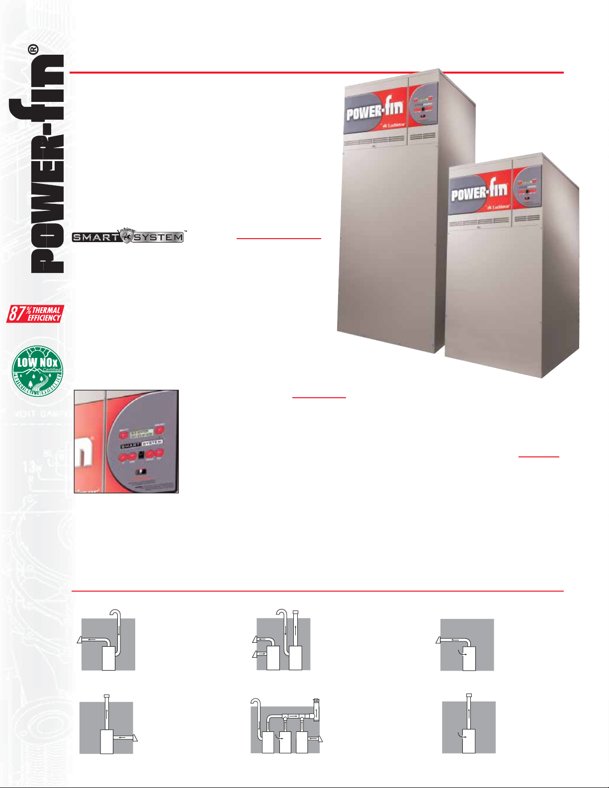
500,000 to 2,000,000 Btu/hr models
The Next Generation
The latest generation of Power-Fin continues to evolve, with
new “Built-in Advantages” from Lochinvar Corporation
These include expanded burner modulation and the advanced
SMART SYSTEM™ operating control, including a builtin cascading sequencer for up to eight boilers. It has been
designed to operate more efficiently at lower inputs, which
can add up to big savings. Plus, with numerous venting
capabilities, the Power-Fin is even more flexible to install.
And it’s easy to see how the Power-Fin is performing thanks
to a digital control panel. Take a look at what the next
generation of Power-Fin has to offer
.
Control
• Built-in cascading sequencer controls up to 8 units
• 2-line 16-character LCD readout of setup, system status
and diagnostic data in words, not codes.
• Password security
• Pump control for operation of water heater pump
• Pump delay w/freeze protection
• Low NOx operation
• 0-10 Vdc BMS input for easy integration into Building
Management Systems
• Optional SMART SYSTEM PC software for advanced
setup and diagnostics
®
.
Infinite Modulation
With thermal efficiencies up to 87%,
Power-Fin boilers feature infinitely
modulating burner firing rates
(turndown), precisely matching the
firing rate to domestic water load
requirements. The result is better overall
efficiency and less cycling. Power-Fin
boilers may be specified as either 5:1
turndown (502 - 2001), 2:1 turndown (1501 - 2001), or 100% ON/
OFF (502 - 1302). With 5:1 turndown the burner fires as low as
20% of maximum input when demand is lowest and increases
the firing rate up to 100% as demand increases. Models with 2:1
turndown modulate from 50% to 100% of maximum input.
Venting Options
DirectAire Horizontal
Vents horizontally up to 50
equivalent feet using Category IV
vent materials. Draws combustion
air up to 50 ft. from a different
pressure zone.
DirectAire Vertical
Vertical venting up to 50 equivalent
feet using Category I or IV vent
materials. Draws combustion air up
to 50 ft. from a different pressure
5
zone.
Direct Vent
Horizontal or vertical venting up to 50
equivalent feet using Category IV vent
materials. Draws combustion air from
the same pressure zone. This option
only available with 5:1 (M) firing
code models.
Common Venting
Vents multiple units vertically
through one vent termination with
Category II vent materials and draws
combustion air from the room, roof
or sidewall. Vent kit and Category IV
to II conversion kit required.
Gasketless Heat Exchanger
The Power-Fin heat exchanger features an array
of 20 or 24 copper-finned tubes surrounding the
burner for maximum heat transfer. Lochinvar also
pioneered the “gasketless” heat exchanger, which
eliminates the use of O-rings and gaskets. Because
of the time-proven reliability of this design, the
Power-Fin heat exchanger is backed by a 5 year
limited warranty.
Sidewall
Horizontal venting up to 50
equivalent feet using Category
IV vent materials. Draws
combustion air from the room.
Vertical
Vertical venting using
Category I or Category IV
vent materials. Draws
combustion air from
the room.
Page 9

Power-Fin® Boiler Dimensions & Specifications
J
K
M
B
G
P
L
N
C
Power-Fin Boiler Dimensions and Specifications
B9/F9 Net M9 Net
Model Input Thermal Output I=B=R Thermal Output I=B=R B9/F9 M9
Number MBH Efficiency MBH MBH Efficiency MBH MBH A B C D E E F G
PBN0502 500 85.0% 425 370 85.0% 425 370 44-1/2” 28-1/2” 23-1/4” 34” 17-3/4” 19-1/2” 6-1/2” 6”
PBN0752 750 85.0% 638 554 85.0% 638 554 52” 28-1/2” 23-1/4” 41-1/2” 17-3/4” 19-1/2” 6-3/4” 6”
PBN1002 999 85.0% 850 739 85.0% 850 739 59-1/4” 28-1/2” 23-1/4” 48-3/4” 17-3/4” 19-1/2” 7-1/4” 6”
PBN1302 1,300 85.0% 1,105 961 85.0% 1,105 961 67-3/4” 28-1/2” 23-1/4” 57-1/4” 17-3/4” 19-1/2” 8-1/4” 6”
PBN1501 1,500 84.0% 1,260 1,096 85.0% 1,275 1,109 65-1/2” 29-3/4” 27-1/4” 58-3/4” 21” 21” 13-1/2” 8”
PBN1701 1,700 84.0% 1,428 1,242 85.0% 1,445 1,257 70” 29-3/4” 27-1/4” 63-1/4” 21” 21” 13-1/2” 8”
PBN2001 2,000 84.0% 1,680 1,461 85.0% 1,700 1,478 76-3/4” 29-3/4” 27-1/4” 70” 21” 21” 13-1/2” 8”
Vent Sizes Shipping
Model B9/F9 M9 Gas Air B9/F9 M9* M9 Wt.
Number H J K L M N P P Conn. Inlet Cat I Cat II Cat IV (lbs)
PBN0502 8” 7-3/4” 23” 11-1/2” 11-1/4” 17-1/2” 15-1/4” 15-1/4” 1” 5” 7” 7” 4” 505
PBN0752 8” 7-3/4” 30-1/2” 11-1/2” 11-1/4” 17-1/2” 15-1/4” 15-1/4” 1-1/4” 5” 9” 9” 5” 554
PBN1002 8” 7-3/4” 37-3/4” 11-1/2” 11-1/4” 17-1/2” 15-1/4” 15-1/4” 1-1/4” 6” 10” 10” 6” 603
PBN1302 8” 7-3/4” 46-1/4” 11-1/2” 19-1/2” 17-1/2” 15-1/4” 15-1/4” 1-1/4” 6” 12” 12” 8” 652
PBN1501 10” 9-1/2” 43-1/2” 5-3/4” 22-1/4” 21-1/2” 24-1/2” 19-1/2” 1-1/2” 6” 12” 8” 6” 1,065
PBN1701 10” 9-1/2” 48” 5-3/4” 25” 21-1/2” 24-1/2” 19-1/2” 1-1/2” 7” 14” 9” 7” 1,100
PBN2001 10” 9-1/2” 54-3/4” 5-3/4” 27-1/2” 21-1/2” 24-1/2” 19-1/2” 1-1/2” 8” 14” 10” 8” 1,127
Notes: Change ‘N’ to ‘L’ for LP Gas Model. No deration on LP models. All water connections are 2-1/2” *w/CAT II conversion kit
Standard Features
• Up to 87% Thermal Efficiency (M)
• Up to 85% Thermal Efficiency (B/F)
• Modulating Burner with 5:1 Turndown
• Hot Surface Ignition
• Low NOx Operation
• Sealed Combustion
• Low Gas Pressure Operation
• Vertical & Horizontal Venting
• Venting up to 50 Feet
• Category I or Category IV Venting
• Cat IV converts to Cat II
w/ optional vent kit
• ASME Copper-Finned Tube
Heat Exchanger
• ASME Certified, “H” Stamped
• Gasketless design
• 160 psi working pressure
• On/Off Switch
• Adjustable High Limit w/ Manual Reset
• Flow Switch
• Low Air Pressure Switch
• Downstream Test Cocks
• 50 psi ASME Relief Valve
• Combustion Air Filtration
• Temperature & Pressure Gauge
• Zero Clearances to Combustible Material
• 1 Year Warranty on Parts
• 10 Year Limited Warranty
(See Warranties for Details)
Smart System Features
• SMART SYSTEM Operating Control
• 2 line, 16 Character Display
• Dual Level Password Security
• Domestic Hot Water Prioritization
• Built in Cascading Sequencer
for up to 8 Boilers
• Building Management System
Integration with 0-10 VDC Input
• Outdoor Reset Control
with Outdoor Air Sensor
• Low Water Flow Safety Control & Indication
• Inlet & Outlet Temperature Readout
• Freeze Protection
• Service Reminder
• Time Clock
• Data Logging
• Hours Running, Space Heating
• Hours Running, Domestic Hot Water
• Ignition Attempts
• Last 10 Lockouts
• Programmable System Efficiency
Optimizers
• Night Setback
• Anti-Cycling
• Outdoor Air Reset Curve
• Ramp Delay
• Boost Temperature & Time
• Three Pump Control
• System Pump
• Boiler Pump
• Domestic Hot Water Pump
• High Voltage Terminal Strip
• 120 VAC / 50-60 Hertz /
1 Phase Power Supply
• Three sets of Pump Contacts
with Pump Relays
• Low Voltage Terminal Strip
• 24 VAC Auxiliary Device Relay
• Auxiliary Proving Switch
Contacts
• Flow Switch Contacts
• Alarm on Any Failure Contacts
• Runtime Contacts
• DHW Thermostat Contacts
• Room Thermostat Contacts
• System Sensor Contacts
• DHW Tank Sensor Contacts
• Outdoor Air Sensor Contacts
• Cascade Contacts
• 0-10 VDC BMS External
Control Contact
Firing Control Systems
• M Indicates 5:1 Turndown, Category IV
• B Indicates 2:1 Turndown, Category I
• F Indicates 100% On/Off Fire, Category I
• M9 Standard
• B9 or F9 Special Order,
Factory Trimmed
• M7, B7 or F7 California Code
• M13, B13 or F13 CSD1/FM/GE Gap
Optional Equipment
• Alarm Bell
• Cupro-Nickel Heat Exchanger
• High & Low Gas Pressure Switches
w/ Manual Reset
• Low Water Cutoff
w/ Manual Reset & Test
• SMART SYSTEM PC Software
• Vent Kits:
- Horizontal Exhaust Cap
- Horizontal Air Intake Cap
- Horizontal Direct Vent Kit
- Category IV to Category II
Conversion Kit
Registered under U.S. Patent # 7,506,617
500,000 - 2,000,000 Btu/hr models
6
Page 10

The Smartest Choice for Condensing Boiler Performance
The KNIGHT® XL, engineered with Lochinvar’s exclusive SMART SYSTEM™ control
and an array of other innovative features, places it far ahead of any commercial heating
boiler in its class. It promises and delivers ultimate ease of installation and maintenance.
With up to 94.6% thermal efficiency, low-NOx emissions and a fully modulating burner,
it is the best ”green choice” for today’s environmentally focused market.
Five modulating/condensing stainless steel KNIGHT XL boilers are available with
399,999–800,000 Btu/hr inputs and remarkably small space-saving footprints. All are
equipped for direct-vent installation with air intake and exhaust runs up to 100 feet
using PVC, CPVC or AL29-4C vent materials. This range of choices is ideal for lightduty applications such as small hotels, schools and office buildings. For higher-demand
applications, up to eight KNIGHT XL units can be installed utilizing the built-in cascading
sequencer to deliver up to 6.4 million Btu/hr heating capacity.
Control
SMART SYSTEM provides unequalled control and monitoring functions that are easy to
understand and use.
• Multi-Color Graphic LCD Display
• Navigation Dial
• USB Port
• Modbus Capability (Optional)
• DHW Modulation Limiting
• DHW Night Setback*
• Controls up to three different setpoint temperatures
• 0-10 V Boiler Rate Output
• 0-10V Signal to control variable speed boiler pump*
• 0-10V System Pump Signal Input*
• Heat Demand from 0-10V Input
• Installer to Program Name and Number into the Boiler
• Freeze Protection Parameters Installer Adjustable
• Separately adjustable SH/DHW Switching times*
• Installer access to BMS and ramp delay settings
*Exclusive to Lochinvar Smart System
Advanced Negative Regulation Technology
KNIGHT XL safely and reliably operates with supply gas pressure as low as 4
inches water column. Negative Regulation (Neg/Reg) technology automatically
adjusts fan speed that ensures the correct volume and mix of fuel and air
throughout the firing range.
Two-in-One Stainless Steel Heat Exchanger
A primary heat exchanger combined with a secondary heat exchanger captures
flue gas heat and condenses to utilize available latent energy. The stainless steel,
pH-tolerant design features a weld-sealed assembly with no O-rings or gaskets
and does not require special glycol. ASME Section IV approved and stamped.
Fully Modulating Burner
The SMART SYSTEM allows fully modulating combustion with 5:1 turndown.
The burner can fire as low as 20% of maximum input and modulates the firing
rate up to 100% as demand increases. The burner is a single stainless steel
assembly covered with woven steel mesh and fires in a 360° pattern along the entire length of the primary heat exchanger. This
allows the compact KNIGHT XL to exceed the capacity of units with larger multiple burners.
Direct Venting up to 100 Feet
KNIGHT XL offers 7 venting options and tremendous flexibility for placement of units within
the building, because it permits direct-vent air intake and exhaust runs up to 100 equivalent feet
using either PVC, CPVC or AL29-4C stainless steel vent pipe. A sidewall vent termination kit is
shipped standard with every KNIGHT boiler.
7
Page 11
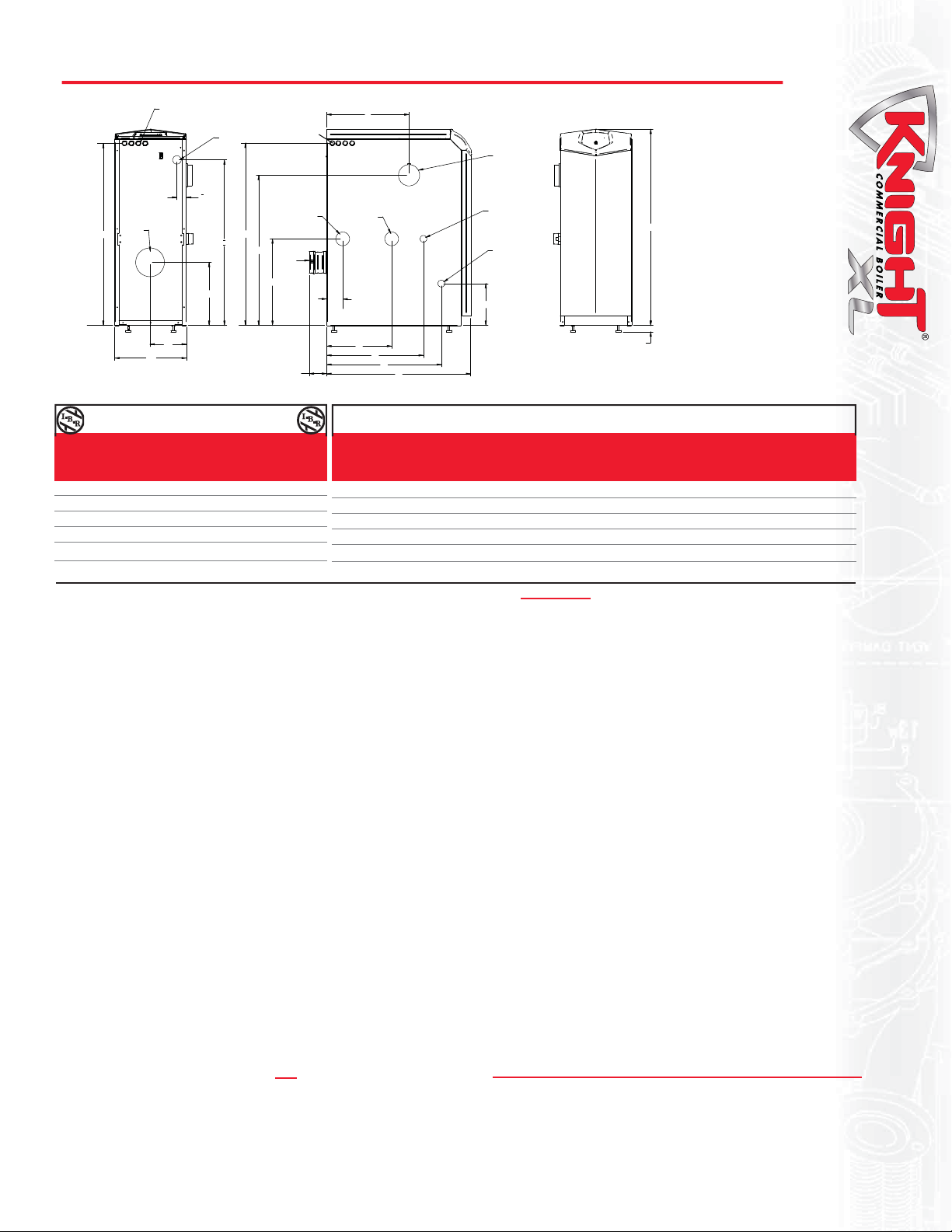
KNIGHT XL® Boiler Dimensions & Specifications
A
LOW VOLTAGE
ELECTRICAL
CONNECTIONS
GAS
HIGH VOLTAGE
ELECTRICAL
CONNECTIONS
K
AIR INLET
39-1/2"
FLUE
B
BACK
J
INLET
38-3/4"
I
H
FLUE
13-3/4"
8"
18-3/4"
D
3-1/2"
OUTLET
G
F
E
C
LEFT SIDE
HEAT
EXCHANGER
DRAIN
3/4" NPT
CONDENSATE
DRAIN
9"
Knight XL Heating Boiler Dimensions and Specifications
Input Net
Model Min Max Thermal Output I=B=R
Number MBH MBH Efficiency MBH MBH
KBN400 80 399 93.3% 373 324
KBN501 100 500 93.3% 467 406
KBN601 120 600 94.6% 567 493
KBN701 140 700 94.3% 660 574
KBN801 160 800 94.0% 752 654
Notes: Indoor installation only. All information subject to change. Change “N” to “L” for LP gas models.
Standard Features
• Up to 94.6% Thermal Efficiency
• Modulating Burner with 5:1 Turndown
• Direct-Spark Ignition
• Low NOx Operation
• Sealed Combustion
• Low Gas Pressure Operation
• ASME Stainless Steel Heat Exchanger
• ASME Certified, ”H” Stamped
Gasketless Heat Exchanger
• 160 psi Working Pressure
• 50 psi ASME Relief Valve
• Highly efficient, condensing design
• Vertical & Horizontal Direct-Vent
• Category IV venting up to 100 feet
• PVC, CPVC or AL29-4C Venting up to 100 Feet
• Factory Supplied Sidewall Vent Termination
• Smart System Control
• Other Features
• On/Off Switch
• Adjustable High Limit w/ Manual Reset
• Automatic Reset High Limit
• Flow Switch
• Flue Temperature Sensor
• Low Air Pressure Switch
• Temperature & Pressure Gauge
• Adjustable Leveling Legs
• Condensate Trap
• Zero Clearances to Combustible Material
• 10 Year Limited Warranty (See Warranty)
Firing Control Systems
• M9 Standard Construction
• M7 California Code
• M13 CSD1 / FM / GE Gap (KB501-KB801)
A B C D E F G H I J K Gas Water Air Vent Shipping
Conn. Conn. Inlet Size Wt. (lbs.)
42-1/2” 15-1/2” 27-3/4” 3-3/4” 20-3/4” 21” 14” 34” 34” 2” 18-3/4” 1” 1-1/2” 4” 4” 280
42-1/2” 15-1/2” 31-1/2” 3-3/4” 25-1/2” 21” 14” 32-1/2” 36” 2” 18” 1” 1-1/2” 4” 4” 310
42-1/2” 15-1/2” 36-1/4” 3-3/4” 25” 21” 14” 36” 32-3/4” 5-1/2” 19-1/2” 1” 2” 4” 4” 340
42-1/2” 15-1/2” 40-1/4” 3-3/4” 29” 23” 17” 36” 32-3/4” 3-1/4” 23-1/2” 1” 2” 4” 6” 370
42-1/2” 15-1/2” 45-1/4” 3-3/4” 33-1/4” 23” 17” 36” 32-3/4” 3-1/4” 27-3/4” 1” 2” 4” 6” 405
Smart System Features
• SMART SYSTEM Digital Operating Control
• Multi-Colored Graphic LCD Display w/ Navigation Dial
• Three Reset Temperature Inputs
with curves for three set point temperature inputs
• Built in Cascading Sequencer for up to 8 Boilers
• Lead Lag
• Efficiency Optimization
• Outdoor Reset Control with Outdoor Air Sensor
• Programmable System Efficiency Optimizers
• Night Setback
• DHW Night Setback
• Anti-Cycling
• Outdoor Air Reset Curve
• Ramp Delay
• Boost Temperature & Time
• Three Pump Control
System Pump With Parameter for Continuous Operation
•
• Boiler Pump With Variable Speed Pump Control*
• Domestic Hot Water Pump
• Domestic Hot Water Prioritization
• DHW tank piped with priority in the boiler loop
• DHW tank piped as a zone in the system with
the pumps controlled by the Smart System
• DHW Modulation Limiting
• Separately Adjustable SH/DHW Switching Times*
• Building Management System Integration
• 0-10VDC Input to Control Modulation or Set Point
• 0-10VDC Input Signal from Variable Speed
System Pump*
• 0-10VDC Modulation Rate Output
• 0-10VDC Input to Enable/Disable call for heat
• Access to BMS Settings through Display
Optional Equipment
• Alarm Bell
• Condensate Neutralization Kit)
• Concentric Vent Kit (KB400-KB601)
• High & Low Gas Pressure Switches
w/ Manual Reset (KB501-KB801)
1-1/4"1/4" -
ADJUSTABLE
FRONT
• High Voltage Terminal Strip
• 120 VAC / 60 Hertz / 1 Phase Power Supply
• Three sets of Pump Contacts with Pump Relays
• Low Voltage Terminal Strip
• 24 VAC Device Relay
• Proving Switch Contacts
• Flow Switch Contacts
• Alarm on Any Failure Contacts
• Runtime Contacts
• DHW Thermostat Contacts
• 3 Space Heat Thermostat Contacts
• System Sensor Contacts
• DHW Tank Sensor Contacts
• Outdoor Air Sensor Contacts
• Cascade Contacts
• 0-10 VDC BMS External Control Contact
• 0-10VDC Boiler Rate Output Contacts
•
0-10VDC Variable Speed System Pump Signal Input
• 0-10VDC Signal to Control Variable Speed Boiler Pump
• Modbus Contacts
• Time Clock
• Data Logging
• Hours Running, Space Heating
• Hours Running, Domestic Hot Water
• Ignition Attempts
• Last 10 Lockouts
• Other Features
• Low Water Flow Safety Control & Indication
• Password Security
• Inlet & Outlet Temperature Readout
• Customizable Freeze Protection Parameters
• Custom Maintenance Reminder with Contractor Info
*Exclusive feature, available only from Lochinvar
• Modbus Communication
• Low Water Cutoff w/Manual Reset & Test
• SMART SYSTEM PC Software
• Stainless Steel Vent Kits (KB701-KB801)
• Stack Frame
8
Page 12

®
The Foundation of Lochinvar Becomes Stronger
Copper-finned tube, non-condensing appliances are the
foundation of Lochinvar’s success. In 1993, Lochinvar
introduced the Copper-Fin II, the first horizontal chassis,
copper-finned tube boiler to operate with fan-assisted
combustion. Now, the Copper-fin II is even better.
Along with high thermal efficiency, gasketless heat
exchangers and multiple venting options we have added
Lochinvar’s exclusive SMART SYSTEM™ control.
Nine models from 399,999 to 2,070,000 Btu/hr input
provide you with exceptional products with a long
list of new features in addition to the established features which redefined the industry. The Copper-fin II was the first
proportional fired, fan-assisted boiler on the market. Every model features a small footprint for easy passage through a
36” door, low NOx – third party tested to less than 20 PPM, Stack Frames that can put twice the Btu/hr input in the same
space and vent diameters up to 8” smaller than conventional atmospheric boilers.
SMART SYSTEM Puts More Control and Information at your Fingertips
The most exciting addition to the Copper-Fin II is the SMART SYSTEMTM control. The SMART SYSTEM is an advanced,
state of the art integrated operating control. We introduced the SMART SYSTEM control in 2005 and it has delivered proven
operation in thousands of demanding commercial applications. The control provides the installer, owners and operators with
precise temperature control and diagnostic information.
Advanced features include:
• 2-Line, 16 Character LCD display of Setup, System Status and Diagnostic Data in Words, not codes
• Built-in Cascade sequencer controlling up to 8 Boilers
• Outdoor Reset adjusts setpoint based on reset curve
• Domestic hot water prioritization allows the boiler to provide space heating and produce domestic hot
water all in one system
• 0-10 VDC BMS Input to control boiler operation
• Modbus protocol - optional
Proportional Firing
Proportional firing divides a single manifold of multiple burners into smaller, independent stages.
With up to four stages of individual operation, the Smart System control can reduce the firing rate down to approximately 25%
Btu/hr input. This simple but effective design matches the boiler’s firing capacity to the constantly changing system demand.
Full Fire or On/Off combustion systems often fire the entire gas train in short, inefficient bursts. Stage firing delivers the Btu’s
required in smoother and longer burn cycles which will improve operation and reduce component fatigue.
Gasketless Heat Exchanger
In 1989, Lochinvar was the first water heater manufacturer to offer gasketless cast iron & copper-finned tube heat
exchangers. Our unique gasketless design enhances reliability by eliminating o-rings and gaskets found on other brands.
The heat exchanger features glass lined headers and copper-finned tubes with extruded integral fins spaced 7-fins per inch
for exceptional heat transfer. The heat exchanger is built to ASME construction standards for 160 psi working pressure
and is backed by a ten year limited warranty.
Venting Options
Conventional
Vents into
conventional
flue or vent
breaching using
Type B double
wall vent.
Powered Sidewall DirectAire Vertical
Vents directly
through the outside
wall using an
optional powered
sidewall cap. Ideal
when a vent stack
9
is not practical.
Sidewall DirectAire Vertical w/ Sidewall Outdoor
Draws fresh air from
inside the room. Vents
up to 50 equivalent
feet
directly through
the outside wall
without the need for a
powered sidewall cap.
Draws fresh air
from outside and
vents through
conventional
vertical flue.
Power DirectAire Horizontal
Draws fresh
air from
outside and
vents through
conventional
vertical flue.
Aire-Lock Direct Vent
Draws fresh air
from outside
and vents
through sidewall
using optional
powered vent
cap.
Requires optional
outdoor vent cap.
Use when indoor
space is a problem
or if outdoor
location gives
better access.
Draws fresh air
50 equivalent feet
from a sidewall.
Vents horizontally
up to 50 equivalent
feet through the
sidewall.
Page 13

Copper-Fin II® Boiler Dimensions & Specifications
E
GAS CONNECTION
0402-0752
A
INLET AIR
FILTER
B
G
D
F
OUTLET
H
C
INLET
GAS CONNECTION
0992-2072
G
Copper-Fin II Heating Boiler Dimensions & Spec i fi ca tions
Net
Model Input Thermal Output I=B=R Vent Air Gas Shipping
Number MBH Efficiency MBH MBH A B C D E F G H Size Inlet Conn Weight
CHN0402 399 85% 339 295 31-1/2” 37-3/4” 22-1/4” 12-1/2” 7” 7” 29” 6-1/2” 6” 6” 1-1/4” 378
CHN0502 500 85% 425 370 31-1/2” 45-1/2” 22-1/4” 12-1/2” 7” 7” 29” 6-1/2” 6” 6” 1-1/4” 414
CHN0652 650 85% 553 481 31-1/2” 56-3/4” 22-1/4” 12-1/2” 8-1/2” 8-1/4” 29” 6-1/2” 8” 8” 1-1/4” 500
CHN0752 750 85% 638 555 31-1/2” 64” 22-1/4” 12-1/2” 8-1/2” 8-1/4” 29” 6-1/2” 8” 8” 1-1/4” 543
CHN0992 990 85% 842 732 36” 48-1/4” 33-1/2” 15-3/4” 8-1/2” 8-1/2” 33-3/4” 8-3/4” 10” 10” 2” 773
CHN1262 1,260 85% 1,071 931 36” 58-1/2” 33-1/2” 15-3/4” 10-1/2” 9-1/2” 33-3/4” 8-3/4” 12” 12” 2” 863
CHN1442 1,440 85% 1,224 1,064 36” 68-3/4” 33-1/2” 15-3/4” 10-1/2” 10-1/2” 33-3/4” 8-3/4” 12” 12” 2” 965
CHN1802 1,800 85% 1,530 1,330 36” 82-1/4” 33-1/2” 15-3/4” 11” 11” 33-3/4” 8-3/4” 14” 12” 2” 1,100
CHN2072 2,070 85% 1,760 1,530 36” 92-1/2” 33-1/2” 15-3/4” 11” 11” 33-3/4” 8-3/4” 14” 12” 2” 1,219
Notes: Change ‘N’ to ‘L’ for LP gas models. No deration on LP models Water connections for models CH 0402-0752 are 2” NPT on 6-1/2” centers.
Header increases “B” dimension 3-1/2” for models CH 0402-0752 and 6-1/4” for models CH 0992-2072. Water connections for models CH 0992-2072 are 2-1/2” NPT on 11-1/4” centers.
Performance data is based on manufacturer test results.
®
Standard Features
• 85% Thermal Efficiency (AHRI Certified)
• Proportional Firing up to 4:1 Turndown
• Hot Surface Ignition
• Low NOx Operation
• Sealed Combustion
• Low Gas Pressure Operation
• Vertical & Horizontal Venting
• Category I Venting
• Double Wall “B” Vent Material
• Category IV Venting
• AL29-4C Stainless Steel Vent Material
• ASME Copper Finned Tube Heat Exchanger
• ASME Certified, “H” Stamped
• Gasketless design
• 160 psi working pressure
• On/Off Switch
• Combustible Floor Rated (0992 - 2072)
• Adjustable High Limit w/ Manual Reset
• Flow Switch
• Low Air Pressure Switch
• Inlet & Outlet Temperature Sensors
• Easy Access Terminal Strips
• Downstream Test Cocks
• 50 psi ASME Pressure Relief Valve
• Temperature & Pressure Gauge
• 1 Year Warranty on Parts (See Warranty for Details)
• 10 Year Limited Warranty (See Warranty for Details)
Optional Equipment
• Alarm Bell
• High & Low Gas Pressure Switches w/ Manual Reset
• Cupro-Nickel Heat Exchanger
• Low Water Cut Off, Probe Type w/ Manual Reset &
Test
• Modbus Communications
• Combustible Floor Kit (0402-0752)
• Stack Frame
Smart System™ Features
• SMART SYSTEM™ Operating Control
• 2 Line/16 Character LCD Display
• Built in Cascading Sequencer for up to 8 boilers
• Front End Loading with Crest boilers
• Building Management System Integration
with 0-10 VDC Input
• Outdoor Reset Control with Outdoor Air Sensor
• Password Security
• Domestic Hot Water Prioritization
• Low Water Flow Control & Indication
• Inlet & Outlet Temperature Readout
• Freeze Protection
• Service Reminder
• Time Clock
• 0-10V DC Rate Output
• Condensing Protection
• 0-10V System Pump Speed Input
• Data Logging
• Hours Running, Space Heating
• Hours Running, Domestic Hot Water
• Ignition Attempts
• Last 10 Lockouts
• Programmable System Efficiency Optimizers
• Night Setback
• Anti-Cycling
• Outdoor Air Reset Curve
• Boost Temperature & Time
Firing Codes
•
M7 Firing Code - California Code
• M9 Firing Code - Hot Surface Ignition
with Electronic Supervision
• M13 Firing Code - CSD1 / Factory Mutual / GE Gap
Certifications
ANSI Z21.13/CSA 4.9 certified
South Coast Air Quality Management District registered
Texas Commission on Environmental Quality
• Three Pump Control
• System Pump
• Boiler Pump
• Domestic Hot Water Pump
• High Voltage Terminal Strip
• 120 VAC / 60 Hertz / 1 Phase Power Supply
• Pump Contacts with Pump Relay
• Low Voltage Terminal Strip
• 24 VAC Auxiliary Device Relay Output - Louvers
• Auxiliary Proving Switch Contacts - Louvers
• 3-way Valve Contacts for Low
Temperature Protection
• Alarm on Any Failure Contacts
• 0-10V System Pump Speed Contacts
• Runtime Contacts
• DHW Thermostat Contacts
• DHW Tank Sensor Contacts
• Unit Enable/Disable Contacts
• System Sensor Contacts - Supply and Return
• Outdoor Air Sensor Contacts
• Contacts for Air Louvers
• Contacts on Any Failure
• Cascade Contacts
• 0-10 VDC BMS External Control Contact
• 0-10 VDC Rate Contacts
• Low Water Temperature Valves
10
Page 14

®
Energy Efficient, Cost Effective Boilers
Lochinvar first introduced Copper-Fin technology to the
boiler industry some 50 years ago. Since then, we’ve
continued to refine and perfect it - adding advanced
fan-assisted combustion, hot surface ignition, a unique
gasketless cop per finned tube heat ex chang er and highly
efficient insulating materials.
Installation Flexibility and Cost-Savings
With compact sizes that use less floor space than ever
before, all Copper-Fin units are narrow enough to fit
through a standard 36” doorway – an ad van tage most
commercial boilers can’t provide. Plus, thanks to special
insulating materials, Copper-Fin units require only 3”
clearance from combustible walls. What’s more, our
Stack Frame allows you to install two units in the area
normally required for one. This makes it easier to fit
Copper-Fin
multiple Copper-Fin boilers into cramped me chan i cal rooms. And you can even use a smaller diameter vent stack - up to 8” smaller
than typically required for comparable atmospheric boilers - so it saves money as well as valuable mechanical room space.
Unique Copper-Fin Heat Ex chang er
The Lochinvar Copper-Fin boiler design uses a two pass heat ex chang er. Water is circulated through a row of
high ly-efficient, finned copper tubes. The high rate of water flow creates a scour ing action that prevents sed i-
ment and lime-scale buildup, common in conventional boilers, and the finned copper tubes allow maximum
heat transfer efficiency.To create this special heat transfer capability, Lochinvar extrudes the fins from
thick wall copper tubing to precise specifications - ex act ly 7 fins per inch. The result is an integrally-
finned tube with a heat transfer ratio 9 times greater than a plain copper tube.
Heavy-Duty Gasketless Design
What’s more, advanced casting processes allowed Lochinvar to develop a unique one-piece
header system. This gasketless design provides enhanced reliability, improved durability and
optimum performance - without the problems or failures common with O-rings and gaskets.
Meets the Toughest Air Quality Standards
Because of our unique fan-assisted combustion process, the Copper-Fin exceeds today’s toughest NOx emissions requirements. An
independent certification laboratory test gave us a rating of less than 20 ppm - corrected to 3% O2. And less NOx means a cleaner
environment.
Enhanced to Provide Performance and Serviceability
Our enhanced Copper-Fin models offer the same reliable operation, and feature a more service friendly
design. The down stream test valves and referenced gas valves are now in the upper deck for easier
access, and the electrical and BMS connections have been repositioned to the front of the unit for easier
installation.
The gas valves, which are referenced to the sealed combustion chamber, improve operational performance
by monitoring the pressure in the sealed combustion chamber and adjusting gas flow to maintain the
optimum air/fuel mixture. And the built-in air inlet filter reduces maintenance and improves performance
by trapping dust and airborne particulates that can foul the burners and blowers.
With dual sight glasses (one on each end), you can easily monitor burner performance and flame
characteristics throughout the entire combustion chamber.
The operator interface panel provides two-stage electronic temperature control and comprehensive
diagnostic status without opening the control panel. Its user friendly design simplifies service while
providing additional diagnostic information through a series of LEDs.
11
Page 15

Copper-Fin® Boiler Dimensions & Specifications
Copper-Fin Heating Boiler Dimensions & Spec i fi ca tions
Input Heating Net
Model Max Thermal Capacity I=B=R Gas Vent Shipping
Number MBH Efficiency MBH MBH A B C D E F G Conn. Size Weight
CBN0497 495 81% 401 349 31-1/2” 45-1/4” 22-1/4” 12-1/2” 9-1/2” 22-3/4” 29-1/2” 1-1/4” 6” 440
CBN0647 645 81% 522 454 31-1/2” 56-3/4” 22-1/4” 12-1/2” 9-1/2” 28-1/2” 29-1/2” 1-1/4” 8” 510
CBN0747 745 81% 603 524 31-1/2” 64” 22-1/4” 12-1/2” 9-1/2” 32” 29-1/2” 1-1/4” 8” 550
CBN0987 985 81% 798 694 36” 48-1/4” 33-1/2” 15-3/4” 8-1/2” 8-1/2” 33-3/4” 2” 10” 845
CBN1257 1255 81% 1,017 884 36” 58-1/2” 33-1/2” 15-3/4” 9-1/2” 10-1/2” 33-3/4” 2” 12” 905
CBN1437 1435 81% 1,162 1,010 36” 68-3/4” 33-1/2” 15-3/4” 10-1/2” 10-1/2” 33-3/4” 2” 12” 1050
CBN1797 1795 81% 1,454 1,264 36” 82-1/4” 33-1/2” 15-3/4” 11” 11” 33-3/4” 2” 14” 1193
CBN2067 2065 81% 1,673 1,455 36” 92-1/2” 33-1/2” 15-3/4” 11” 11” 33-3/4” 2” 14” 1350
Notes: Change ‘N’ to ‘L’ for LP gas models. Water connections for models CB 0497-747 are 2” NPT on 6-1/2” centers.
No deration on LP models. Water connections for models CB 0987-2067 are 2-1/2” NPT on 11-1/4” centers.
Performance data based on manufacturer test results.
Copper-Fin
®
Standard Features
• 81% Thermal Efficiency
• Electronic Temperature Control
• Fan Assisted Combustion
• Sealed Combustion Chamber
• Stainless Steel Burners
• Low NOx Operation Exceeds the most
Stringent Air Quality Requirements
• ASME Copper Finned Tube
Heat Exchanger
• 160 psi Working Pressure
• Gasketless Heat Exchanger Design
• Pump Relay w/ Delay
• Down Stream Test Valve
• Referenced Gas Valves
• Loch-Heat Ceramic Tile
Combustion Chamber
• Hot Surface Ignition
• Adjustable High Limit w/ Manual Reset
• ASME Pressure Relief Valve
• Temperature & Pressure Gauge
• Flow Switch
• 24 Volt Control System
• BMS Terminal Strip
• Combustion Air Filter
• Freeze Protection
• 10 Year Limited Warranty on Heat
Exchanger (See warranty for details)
Optional Equipment
• Alarm Bell
• Contacts on any Failure & Runtime
• Contacts for Air Louvers
• Cupro-Nickel Heat Exchanger
• High & Low Gas Pressure Switch
w/ Manual Reset
• Outdoor Reset Control
• Manual Reset Low Water Cut-Off
w/ test
• Stack Frame
• MP2 Sequencer
Available Firing Systems
M9 Hot Surface Ignition with
Electronic Supervision (Standard)
M13 GE GAP/FM/CSD1
M7 California Code
Venting
• Outdoor Vent Cap
Registered under U.S. Patent # 5,989,020
12
Page 16

®
Lightweight, Flexible and
Energy Efficient
Copper-Fin gas-fired atmospheric boilers are
high-efficiency boilers that save space, save
money, are lightweight, and are simple to service
and install. Copper-Fin boilers are equipped with
a built-in draft hood, a highly efficient copper
finned tube heat exchanger, our own specially
designed two-stage electronic control system, and
they are approved for installation on combustible
floors. Models are available with inputs from
315,000 to 500,000 Btu/hr.
Two-Stage Control System
The boiler’s two-stage electronic temperature control provides flexibility and saves fuel by
Copper-Fin
closely matching heat output to system demand. On colder days the boiler fires at full output, and
in warmer conditions the boiler reduces heat output to save energy and reduce boiler cycling.
82
%
standard equipment on all Copper-Fin boilers, provides dramatic fuel savings by reducing the firing rate 50%. And the
two-stage firing control is ideal for applications utilizing indoor/outdoor reset.* *I/O reset is available as an option.
During the majority of the heating season, less than full boiler output is required to satisfy the
heat load. For this reason, Lochinvar has developed a two-stage firing system. Two-stage firing -
Copper Finned Tube Heat Transfer
The heart of the Copper-Fin boiler is its copper finned-tube heat exchanger.
With this unique gasketless design, we’ve combined the best of both worlds:
cast iron headers for long-lasting durability, and a copper finned-tube heat
exchanger for high efficiencies and fast heat transfer. The gasketless
heat exchanger design reduces the risk of leaks or system failures that
are common with conventional boilers. Plus, the unit’s low-mass design
means that water gets heated quickly. Not only is heat up time nearly
instantaneous with these boilers, the energy consumption and operating
costs are lower too.
Intermittent Ignition Device
The Intermittent Ignition Device is a solid-state electronic spark-to-pilot ignition system that reduces fuel
consumption. It’s electronic circuitry continuously monitors the system and provides pilot gas only when there
is a call for heat, eliminating the need for a continuously burning pilot, and providing an additional measure of
operational safety.
13
Built-In Draft Hood
The lower overall height of the draft hood makes it easier to install the Copper-Fin boiler in all applications,
especially in those instances where overhead space is limited and headroom restrictions exist.
Serviceability
This boiler is as flexible and convenient to install and service as it is efficient and compact. The heavy-duty stainless
steel burners can easily be adapted for use with either natural or liquefied petroleum (LP) gas, and the boiler’s design
allows for easy access to all major components for servicing. The heat exchanger is designed to slide out the front of
the boiler for faster maintenance, and Lochinvar backs it up with an exclusive 10-year Limited Warranty. For more
information, call your Lochinvar dealer today.
Page 17

Copper-Fin® Boiler Dimensions & Specifications
Copper-Fin Boiler Dimensions & Spec i fi ca tions
Thermal Net
Model Input Efficiency Output I=B=R Gas Vent Ship.
Number MBH % MBH MBH A B C D Conn. Size Weight
CBN315 315 82.0 258 224 29-1/2” 32-1/4” 21-1/2” 16-1/4” 3/4” 8” 245
CBN360 360 82.0 295 257 29-1/2” 35-1/4” 21-1/2” 17-3/4” 1” 9” 255
CBN399 399 82.0 328 285 29-1/2” 44-1/2” 22” 22-1/4” 1” 10” 320
CBN500 500 82.0 410 357 34-1/2” 52-1/2” 22” 26-1/4” 1” 10” 345
Notes: Change ‘N’ to ‘L’ to denote L.P. gas models
No deration for L.P. models.
Water Connections are 2” NPT on 6-1/4” centers.
Performance data is based on manufacturer test results.
Copper-Fin
®
Standard Features
• 82% Thermal Efficiency
• ASME Copper Finned Tube Heat Exchanger
• Gasketless Heat Exchanger Design
• Two Stage Intermittent Electronic Ignition
• 160 PSI Working Pressure
• Pump Relay
• Two Stage Solid State Temperature Control
• Two Stage Gas Valve with Built-In
Manual Shut-Off
• Automatic Reset High Limit
• ASME Pressure Relief Valve
• Temperature & Pressure Gauge
• Diagnostic Flash Codes
• Built-In Draft Diverter
• CSA Design Certified for Alcove Installation
• CSA Design Certified for Installation
on Combustible Floor
• Stainless Steel Burners
• Loch-Heat Ceramic Tile Combustion Chamber
• 24 Volt Control System
• 10 Year Limited Warranty on Heat Exchanger
(See warranty for details)
Optional Equipment
• Adjustable High Limit
w/ Manual Reset
• Contacts on any Failure
• Contacts for Air Louvers
• Flow Switch
• Outdoor Air Reset Control
• Low Water Cut-Off
• Stack Frame
• Pump Delay/Freeze Protection
• MP2 Sequencer
• 3-Way Low Temperature Valve
Firing Controls
• M9 - Two-Stage Intermittent
Spark Ignition (Standard)
• M13 - GE GAP/FM/IRI
• M7 - California Code
14
Page 18

The Best You Can Buy Is Now Even Better!
KNIGHT is recognized for it’s reliable, proven
performance and high quality standards. Its award
winning design assures contractors and home owners
peace of mind and long term savings in operating costs.
Now, Lochinvar has raised the KNIGHT standard to
even greater heights. The dramatically enhanced SMART
SYSTEM™ control with color display gives installers
and maintenance personnel a greater level of control
than ever before. It’s easier to access all the information
they need to setup, troubleshoot and monitor all boiler
functions. Additionally, two new cascading options allow
the installer to fine-tune sequencing of multiple boiler
installations.
More than ever, KNIGHT is the best choice for
traditional hydronic space heating, radiant floor heating and domestic hot water applications.
Control
The new SMART SYSTEM™ is the most advanced integrated boiler control
on the market today.
Larger LCD Screen - Displays more information.
Soft Keys - For simple programming.
Navigation Dial - For fast transitions from screen to screen and easy
adjustment of settings.
USB Port - USB port permits connection to a laptop computer. SMART
SYSTEM PC software may be used to troubleshoot and program KNIGHT
functions, set date and time, monitor historical data, including faults, trends and
energy consumption.
Built-in Cascading Sequencer
When multiple KNIGHT boilers are installed together, the SMART SYSTEM built-in
sequencer can be set for “Lead-Lag” cascade or “Efficiency Optimized” cascade operation.
Advanced Negative Regulation Technology
KNIGHT safely and reliably operates with supply gas pressures as low as 4 inches water
column. Plus “Neg/Reg” technology automatically adjusts gas pressure to ensure the
correct volume of fuel and air entering the burner.
Direct-Spark Ignition
With each call for heat, two electrodes ignite the fuel/air mixture. A third electrode then
senses for flame. The SMART SYSTEM will generate a soft lockout and display a fault if
ignition does not occur after 3 attempts.
®
15
Fully Modulating Burner with 5:1 Turndown
The SMART SYSTEM allows fully modulating combustion with 5:1 turndown. The burner
can fire as low as 20% of maximum input and modulates the firing rate up to 100% as
demand increases. A woven stainless steel mesh enclosed burner tube fires in a 360° pattern
along the entire length of the primary heat exchanger.
Two-in-One Stainless Heat Exchanger
A primary heat exchanger combined with a secondary heat exchanger captures flue gas
heat and condenses to utilize available latent energy. The stainless steel, pH-tolerant design
features a weld-sealed assembly with no O-rings or gaskets and does not require special glycol.
ASME Section IV approved and stamped
Page 19

KNIGHT® Boiler Dimensions & Specifications
Models:
KBN 081-211
Floor-Standing
Models
Model:
KBN286
Knight Heating Boiler Dimensions and Specifications
Input Heating NET
Model Min. Max. AFUE Capacity I=B=R
Number MBH MBH % MBH MBH
WBN051 10 50 95.3 45 39
WBN081 16 80 95.3 72 63
WBN106 21 105 95.4 94 82
WBN151 30 150 95.5 135 119
WBN211 42 210 95.7 190 165
KBN081 16 80 95.3 72 63
KBN106 21 105 95.4 94 82
KBN151 30 150 95.5 135 119
KBN211 42 210 95.7 190 165
KBN286 57 285 96.0 260 226
Notes: Indoor installation only. All information subject to change. Change "N" to "L" for LP gas models.
Smart System™ Features
• SMART SYSTEM Digital Operating Control
• Multi-Colored Graphic LCD Display
with Navigation Dial and Soft Keys
• Three Setpoint Temperature Inputs
• Built-in Cascading Sequencer for up to 8 Boilers
• Lead Lag
• Efficiency Optimization
• Outdoor Reset Control with Outdoor Air Sensor
• Programmable for Three Reset Temperature Inputs
• Programmable System Efficiency Optimizers
• Night Setback
• DHW Night Setback
• Anti-Cycling
• Outdoor Air Reset Curve
• Ramp Delay
• Boost Temperature & Time
• Three Pump Control
• System Pump with Parameter for
Continuous Operation
• Boiler Pump with Variable Speed Pump Control*
• Domestic Hot Water Pump
• Domestic Hot Water Prioritization
• DHW tank piped with priority in the boiler loop
• DHW tank piped as a zone in the system with
the pumps controlled by the Smart System
• DHW Modulation Limiting
• Separately Adjustable SH/DHW Switching Times*
• Building Management System Integration
• 0-10VDC Input to Control Modulation or Set Point
• 0-10VDC Modulation Rate Output
• 0-10VDC Input Signal from Variable
Speed System Pump*
• 0-10VDC Input to Enable/Disable call for heat
A C D E F G H I J K M Gas Water Air Vent Shipping
Conn. Conn. Inlet Size Wt. (lbs.)
29-1/4" 15-3/4" NA 10-3/4" 10-3/4" 2" 6-3/4" NA 3-1/4" 4-1/4" 2-3/4" 1/2" 1" 2" 2" 130
29-1/4" 15-3/4" NA 10-3/4" 10-3/4" 2" 6-3/4" NA 3-1/4" 4-1/4" 2-3/4" 1/2" 1" 2" 2" 130
29-1/4" 15-3/4" NA 10-3/4" 10-3/4" 3-1/2" 5-1/2" NA 3-1/4" 4-1/4" 2-3/4" 1/2" 1" 2" 2" 134
29-1/4" 20-3/4" NA 15-3/4" 8-1/2" 3-1/2" 5-1/2" NA 8-3/4" 9-3/4" 1-1/2" 1/2"
29-1/4" 25" NA 20" 12" 3-1/2" 5-1/2" NA 13" 14" 1-1/2" 1/2" 1" 3" 3" 177
33-1/4" 14" 7" 5-3/4" 5" 3" 20-1/2" 22" 1-3/4" 6-1/2" NA 1/2" 1" 3" 3" 125
33-1/4" 14" 6-1/2" 5-3/4" 4-1/2" 1-1/2" 20-1/2" 22" 1-3/4" 6-1/2" NA 1/2" 1" 3" 3" 129
33-1/4" 18" 12-1/4" 11-1/2" 10
" 1-3/8" 21-1/4" 23" 1-3/4" 12" NA 1/2" 1" 3" 3" 157
33-1/4" 22-1/4" 16-1/2" 15-3/4" 14-1/4" 5-1/4" 21-1/4" 23" 1-3/4" 16-1/4" NA 1/2" 1" 3" 3" 172
42-1/4" 19-3/4" 12-3/4" 13-1/2" 6" 2" 34" 31" 11-3/4" 4-1/4" NA 3/4" 1-1/4" 4" 4" 224
• High-Voltage Terminal Strip
• 120 VAC / 60 Hertz / 1 Phase Power Supply
• Three Sets of Pump Contacts
• Low Voltage Terminal Strip
• 24 VAC Device Relay
• Proving Switch Contacts
• Flow Switch Contacts
• Alarm on Any Failure Contacts
• Runtime Contacts
• DHW Thermostat Contacts
• 3 Space Heat Thermostat Contacts
• System Sensor Contacts
• DHW Tank Sensor Contacts
• Outdoor Air Sensor Contacts
• Cascade Contacts
• 0-10VDC BMS External Control Contact
• 0-10VDC Boiler Rate Output Contacts
• 0-10VDC Variable Speed System Pump Signal Input
• 0-10VDC Signal to Control Variable
Speed Boiler Pump
• Modbus Contacts
• Time Clock
• Data Logging
• Hours Running, Space Heating
• Hours Running, Domestic Hot Water
• Ignition Attempts
• Last 10 Lockouts
• Access to BMS Settings through Graphic LCD Display
• Maintenance Reminder
• Custom Maintenance Reminder with Contractor Info
• Installer Ability to De-activate Service Reminder
• Low-Water Flow Safety Control & Indication
• Password Security
• Customizable Freeze Protection Parameters
Wall-Mount
Models
Models:
WBN051-211
1" 3" 3" 162
Standard Features
• Energy Star™ Qualified
• Up to 96% DOE AFUE Efficiency
• Modulating Burner with 5:1 Turndown
• Direct-Spark Ignition
• Low-NOx Operation
• Field Convertible from Natural to LP Gas
• ASME Stainless Steel Heat Exchanger
• 30 psi ASME Relief Valve
• Vertical & Horizontal Direct-Vent
• PVC, CPVC or SS Venting up to 100 feet
• Factory Supplied Sidewall Vent Termination
• Smart System Control
• Condensate Trap
• Other Features
• Automatic Reset High Limit
• Adjustable High Limit w/Manual Reset
• Boiler Circulating Pump
• Adjustable Leveling Legs (KB Models only)
• Wall-Mount Bracket (WB Models only)
• Zero Clearances to Combustible Materials
• 12-Year Limited Warranty (See Warranty for Details)
Optional Equipment
• Modbus Communication
• Condensate Neutralization Kit
• Flow Switch
• Low-Water Cutoff w/Manual Reset & Test
• Alarm Bell
• Concentric Vent Kit
• SMART SYSTEM PC Software
• Stack Frame
Firing Control Systems
• M9 Standard Construction
• M7 California Code
16
Page 20

Stainless Steel Fire Tube Heat Exchanger
The KNIGHT® Wall Mount, engineered with Lochinvar’s exclusive SMART
SYSTEM™ control and an array of other innovative features is far ahead of any
heating boiler in its class. It promises and delivers ultimate ease of installation
and maintenance. With up to 99% thermal efficiency, low-NOx emissions and a
fully modulating burner, it is the best ”green choice” for today’s environmentally
focused market.
Seven modulating/condensing stainless steel KNIGHT Wall Mount boilers are
available with 55,000–399,999 Btu/hr inputs in a space-saving wall-mounted
design. All are equipped for direct-vent installation with air intake and exhaust
runs up to 100 feet using PVC, CPVC or AL29-4C vent materials. This range
of choices is ideal for residential or light-duty applications such as small hotels,
schools and office buildings. For higher-demand applications, up to eight
KNIGHT Wall Mount units can be installed utilizing the built-in cascading
sequencer to deliver up to 3.2 million Btu/hr heating capacity.
The new KNIGHT Wall Mount Boiler reflects Lochinvar’s constant commitment
to providing all the options you need to serve every application.
Advanced Negative Regulation Technology
KNIGHT safely and reliably operates with supply gas pressure as low as 4 inches water column.Negative Regulation (Neg/Reg)
technology automatically adjusts fan speed to ensure the correct volume and mix of fuel and air throughout the firing range.
Fire Tube Design
This fully welded ASME Certified stainless steel heat exchanger uses oval shaped tubes to pass
heat from the products of combustion into the water stored in the vessel. To facilitate heat transfer
the tubes are manufactured with dimples to slow the flue products and extract available latent
energy. With a fire tube design the flue products are inside tapered passage ways and the water
passed through a vessel. Since the flue products pass through tubes and the water is circulated
through a larger diameter vessel a fire tube design allows for minimal head pressure loss through
the boiler which allows the boiler to be installed easily into various hydronic applications.
Water-Backed Combustion Chamber
An outstanding feature of the fire tube design is a water backed combustion chamber. By having
the combustion chamber surrounded by water the Knight Wall Mount has more heating surface
area. This larger heating surface area allows for efficiencies up to 99%.
Fully Modulating Burner
The SMART SYSTEM allows fully modulating combustion with 5:1 turndown. The burner
can fire as low as 20% of maximum input and modulates the firing rate up to 100% as demand
increases. The burner is a single stainless steel assembly covered with woven steel mesh and fires
in a 360° pattern along the entire length of the burner. This allows the compact KNIGHT to exceed
the modulation capacities of units with larger multiple burners.
Fully Modulating Burner with 5:1 Turndown
The SMART SYSTEM allows fully modulating combustion with 5:1 turndown. The burner
can fire as low as 20% of maximum input and modulates the firing rate up to 100% as demand
increases. A woven stainless steel mesh enclosed burner tube fires in a 360° pattern along the entire
length of the primary
heat exchanger.
Direct Venting up to 100 Feet
KNIGHT offers 5 venting options and tremendous
flexibility for placement of units within the building,
because it permits direct-vent air intake and exhaust runs
up to 100 equivalent feet using either PVC, CPVC or AL29-4C
stainless steel vent pipe. A sidewall vent termination kit is standard
equipment with every KNIGHT boiler.
17
Page 21

KNIGHT® Boiler Dimensions & Specifications
Knight Heating Boiler Dimensions and Specifications
Input Heating NET
Model Max. Min. AFUE Capacity I=B=R
Number MBH MBH % MBH MBH
WHN055 55 11 96 51 44
WHN085 85 17 96 79 69
WHN110 110 22 96 102 89
WHN155 155 31 96 144 125
WHN199 199 40 96 186 162
WHN285 285 57 96 265 230
WHN399 399 80 95** 379 330
Notes: Indoor installation only. All information subject to change. Change "N" to "L" for LP gas models. **WHN399 value is Thermal Efficiency
A B C D E F G H I J K L M N O Gas Water Air Vent Shipping
Conn. Conn. Inlet Size Wt. (lbs.)
33-1/4” 18-1/2” 16” 11-3/4” 10-1/2” 6-1/2” 4” 1-1/2” 3” 14-1/2” 5-3/4” 4” 3” 16-1/4” 5” 1/2” 1” 2” 2” 139
33-1/4” 18-1/2” 16” 11-3/4” 10-1/2” 6-1/2” 4” 1-1/2” 3” 14-1/2” 5-3/4” 4” 3” 16-1/4” 5” 1/2” 1” 2” 2” 142
33-1/4” 18-1/2” 19” 14-1/2” 10-3/4” 7-3/4” 7-3/4” 2-1/4” 10” 15-1/2” 5” 3-1/4” 3” 16-1/2” 2-3/4” 1/2” 1” 3” 3” 159
33-1/4” 18-1/2” 19” 14-1/2” 10-3/4” 7-3/4” 7-3/4” 2-1/4” 10” 15-1/2” 5” 3-1/4” 3” 16-1/2” 2-3/4” 1/2” 1” 3” 3” 166
33-1/4” 18-1/2” 19” 14-1/2” 11-3/4” 8” 8” 1-1/4” 10” 16-3/4” 4-3/4” 3-1/4” 2-3/4” 16-1/2” 3” 1/2” 1-1/4” 3” 3” 175
33-1/4” 18-1/2” 19” 14-1/2” 11-3/4” 8” 8” 1-1/4” 10” 16-3/4” 4-3/4” 3-1/4” 2-3/4” 16-1/2” 3” 1/2” 1-1/4” 3” 3” 184
35-1/2” 25” 21-3/4” 17-1/2” 12-1/2” 9-1/4” 9-1/2” 2-1/4” 13-1/4” 21-1/2” 9” 4-3/4” 4” 22-1/2” 3-3/4” 3/4” 1-1/2” 4” 4” 213
Smart System™ Features
• SMART SYSTEM Digital Operating Control
• Multi-Color Graphic LCD Display
with Navigation Dial and Soft Keys
• Three Boiler Setpoint Temperature Inputs
• Plus Domestic Hot Water Prioritization
• Built-in Cascading Sequencer for
up to 8 Boilers
• Lead Lag
• Efficiency Optimization
• Outdoor Reset Control with Outdoor
Air Sensor
• Programmable for Three Reset
Temperature Inputs
• Programmable System Efficiency Optimizers
• Night Setback
• DHW Night Setback*
• Anti-Cycling
• Outdoor Air Reset Curve
• Ramp Delay
• Boost Temperature & Time
• Three Pump Control
• System Pump with Parameter for
Continuous Operation
• Boiler Pump with Variable Speed
Pump Control*
• Domestic Hot Water Pump
• Domestic Hot Water Prioritization
• DHW tank piped with priority in
the boiler loop
• DHW tank piped as a zone in the
system with the pumps controlled
by the Smart System
• DHW Modulation Limiting
• Separately Adjustable Space Heat/DHW
Switching Times*
• Building Management System Integration
• 0-10 VDC Input to Control Modulation
or Set Point
• 0-10 VDC Modulation Rate Output
• 0-10 VDC Input to Enable/Disable
call for heat
• Access to BMS Settings through Graphic
LCD Display
• High-Voltage Terminal Strip
• 120 VAC / 60 Hertz / 1 Phase Power Supply
• Three Sets of Pump Contacts
• Low Voltage Terminal Strip
• 24 VAC Device Relay
• Proving Switch Contacts
• Flow Switch Contacts
• Alarm on Any Failure Contacts
• Runtime Contacts
• DHW Thermostat Contacts
• 3 Space Heat Thermostat Contacts
• System Sensor Contacts
• DHW Tank Sensor Contacts
• Outdoor Air Sensor Contacts
• Cascade Contacts
• 0-10 VDC BMS External Control Contact
• 0-10 VDC Boiler Rate Output Contacts
• 0-10 VDC Variable Speed System Pump
Signal Input*
• 0-10 VDC Signal to Control Variable
Speed Boiler Pump*
• Modbus Contacts
• Time Clock
• Data Logging
• Hours Running, Space Heating
• Hours Running, Domestic Hot Water
• Ignition Attempts
• Last 10 Lockouts
• Maintenance Reminder
• Custom Maintenance Reminder with
Contractor Contact Information
• Installer Ability to De-activate
Service Reminder
• Low-Water Flow Safety Control & Indication
• Password Security
• Customizable Freeze Protection Parameters
Standard Features
• Energy Star™ Qualified
•96% DOE AFUE Efficiency
• Modulating Burner with 5:1 Turndown
• Direct-Spark Ignition
• Low-NOx Operation
• Field Convertible from Natural to LP Gas
• ASME Stainless Steel Heat Exchanger
• 30 psi ASME Relief Valve
• Vertical & Horizontal Direct-Vent
• PVC, CPVC or SS Venting up to 100 feet
• Factory Supplied Sidewall Vent Termination
• Smart System Control
• Condensate Trap
• Other Features
• Automatic Reset High Limit
• Adjustable High Limit w/Manual Reset
• Boiler Circulating Pump
• Wall-Mount Bracket
• Zero Clearances to Combustible Materials
• 12-Year Limited Warranty
(See Warranty for Details)
§
Optional Equipment
• Modbus Communication
• Flow Switch
• Low-Water Cutoff w/Manual Reset & Test
• Alarm Bell
• Concentric Vent Kit
• SMART SYSTEM PC Software
• Condensate Neutralization Kit
Firing Codes
• M9 Standard Construction
• M7 California Code
* Exclusive feature, available only from Lochinvar
§ WHN 55-285 only
18
Page 22

It’s the Little Things
The Efficiency+ is quietly heating more and more homes and
small businesses across America and throughout the world.
This quiet revolution is the product of years of research and
development, which has resulted in a boiler that provides all
the bells and whistles typically found on commercial boilers
in a package small enough to fit in a closet. Operating at 84%
thermal efficiency, the Efficiency+ easily meets expectations
and requirements. What makes the Efficiency+ unique is its
ability to focus on the little things - so you don’t have to.
Ease of Installation
When installing the Efficiency+, you’ll notice that the details
have all been taken care of. It’s smaller than most units of
comparable Btu/hr input, so it will fit just about anywhere
you need to put it. And it is available with four venting
options, including horizontal and vertical direct venting,
so wherever you put it, it’s easy to vent - with or without
a masonry chimney. Plus, it weighs less than comparable units
because of design advantages such as a copper finned tube heat
exchanger and Loch-Heat
insulation material - so it can be handled by just one man.
Serviceability
TM
tile - a remarkably light
The Efficiency+ is designed to be installed and forgotten about, quietly and reliably heating away. It includes an integrated
control system that ensures safe burner operation and prevents flame-failures. It continuously monitors the flame and can
even restart the ignition sequence automatically. Plus, the Efficiency+ comes standard with a burner flame observation port
and internal diagnostic lights which can help pinpoint any problems, making trouble-shooting easy.
Two Stage Firing
The Efficiency+ more than lives up to its name with an outstanding 84% thermal efficiency rating.
Two-stage firing is standard on all Efficiency+ boilers, providing dramatic fuel savings by reducing
Btu output by 50%. This means when outdoor temperatures become warmer, the boiler will use
less fuel to maintain comfortable indoor temperatures, matching the heat output to the system
demand and maximizing operating efficiency.
The Details
The Efficiency+ is full of hidden advantages - details you’ll notice when they matter most.
For example, if you live in the Northeast or in the Mountain States, where natural gas supply pressure can be as low as
4 inches of water column, you’ll appreciate the fact that the Efficiency+ is designed to operate on low gas pressure. If you’re
using radiant heating, you’ll love that the Efficiency+ is easy to adapt to the low water temperatures typically used in radiant
heating, and that the unit’s low-mass design means that water gets heated quickly, delivering a quicker response to demand
and providing significant savings. And everyone can appreciate the fact that the Efficiency+ has the lowest NOx rating in
the industry, helping to keep our environment safe.
Venting Options
19
Conventional
Vents into conventional flue or
vent breaching using Type B
double wall vent.
*Requires factory supplied vent kit.
* Outdoor Vent Kit
Use when indoor space is
a problem or if outdoor
location gives better access.
* E+ DirectAire Vent with
Sidewall Inlet
Draws fresh combustion air from
an outside wall horizontally, and
vents combustion by-products
through a vertical flue.
Direct Vent Vertical
Draws fresh combustion
air from outside, and vents
combustion by-products
through a vertical flue.
* Direct Vent Horizontal
Draws fresh combustion air from
outside, then vents by-products
through a side wall.
Page 23

Efficiency+® Boiler Dimensions & Specifications
Efficiency+ Boiler Dimensions & Spec i fi ca tions
Input Heating Net
Model Max AFUE Capacity I=B=R Gas Vent Shipping
Number MBH % MBH MBH B D E G Conn. Size Weight
EBN150 150 83.2 129 112 19-3/4” 16” 7-1/4” 11-3/4” 3/4” 5” 245
EBN200 200 83.1 170 148 23-3/4” 20” 9-1/4” 11-3/4” 3/4” 5” 265
EBN250 250 83.2 218 190 27-1/2” 23-3/4” 11” 11-3/4” 3/4” 6” 290
EBN300 300 84.0 252 219 31-1/4” 27-1/2” 13” 11-3/4” 3/4” 6” 310
Notes: Change ‘N’ to ‘L’ to denote L.P. gas models Electrical Requirements: 120 VAC / 2 AMP Water connections are 1-1/2” NPT
Net ratings based on piping and pick-up allowance of 1.15 Performance data based on manufacturer test results.
Standard Features
• 84% AFUE
• Two Stage Firing
• Sealed Combustion Chamber
• Stainless Steel Burners
• Low NOx Operation Exceeds the most
Stringent Air Quality Requirements
• ASME Copper Finned Tube Heat Exchanger
• 160 PSI Working Pressure
• Gasketless Heat Exchanger Design
• Automatic Reset High Limit
• Loch-Heat Ceramic Tile Combustion Chamber
• Hot Surface Ignition
• ASME Pressure Relief Valve
• 24 Volt Control System
• Pump Relay
• 10 Year Limited Warranty
on Heat Exchanger
(See warranty for details)
Optional Equipment
• Adjustable High Limit
w/ Manual Reset
• Alarm Bell
• Cupro-Nickel Heat Exchanger
• Flow Switch
• Indoor/Outdoor Reset
• Manual Reset Low Water Cut-Off
w/test
• MP2 Sequencer
• Stack Frame
• Pump Delay w/ Freeze Protection
Firing Control Systems
M9 Hot Surface Ignition with
Electronic Supervision
(Standard)
M7 California Code
Registered Under U.S. Patent # 5,989,020
20
Page 24

Flexibility is the Solution
What could be better than a high-efficiency boiler that saves space,
saves money and helps resolve all your heating problems? How
about one that’s lightweight and simple to install, too! That’s the
Solution™ boiler by Lochinvar
finned tube heat exchanger, to our own specially designed two-stage
electronic control system, the Solution boiler offers these features
and many more in models up to 260,000 Btu/hr. Plus, all Solution
boilers are equipped with top water connections, a built-in draft
hood, and are approved for installation on combustible floors.
Copper Finned Tube Heat Transfer
The heart of the Solution boiler is its copper finned-tube heat
exchanger. With this unique gasketless design, we’ve combined the
best of both worlds: cast iron headers for long-lasting durability,
and a copper finned-tube heat exchanger for high efficiencies and
fast heat transfer. The gasketless design reduces the risk of leaks or
system failures that are common with conventional boilers. Plus,
the unit’s low-mass design means that water gets heated quickly. Not only is heat up time nearly instantaneous with the
Solution boiler, the energy consumption and operating costs are lower too, with a rating of 84% AFUE.
Two-Stage Control
The Solution boiler’s two-stage electronic temperature control provides flexibility and saves fuel by
closely matching heat output to system demand. On colder days the boiler fires at full output, and in
warmer conditions the Solution boiler reduces heat output to save energy and reduce boiler cycling.
®
. From the highly efficient copper
During the majority of the heating season, less than full boiler output is required to satisfy the heat
load. For this reason Lochinvar has developed a two-stage firing system. Two-stage firing - standard
equipment on all Solution boilers, provides dramatic fuel savings by reducing the firing rate 50%. Two-stage firing is
ideal for applications utilizing indoor/outdoor reset* and is advantageous in systems where the Solution boiler is used
with an Squire indirect water heater to produce domestic hot water. *Outdoor air reset is available as an option.
PVC/CPVC Vent Kit (optional)
Vent up to 25 feet
out a sidewall
or rooftop with
inexpensive PVC/
CPVC
(CB 45-135).
Simple To Service
The Solution boiler is as flexible and convenient as it is efficient and
compact. For example, the heavy-duty stainless steel burners can easily
be adapted for use with either natural or liquefied petroleum (LP) gas.
What’s more, Solution boilers allow easy access to all major components
for servicing. We even designed the heat exchanger to slide out the
front of the boiler for faster maintenance, and we back it all up with our
exclusive 20-year Limited Warranty.
Built-In Piping Solutions
Other boilers often require system piping upgrades which are
cumbersome and expensive. The Solution boiler eliminates
this problem with its built-in, performance loop. The loop
maintains constant flow through the boiler when only a single
zone of the system is calling for heat. This helps maintain
peak system performance by keeping the copper heat transfer
surface clean and operating at top efficiency. And the top
water connections make replacements a snap by fitting into
existing piping arrangements without additional elbows and
connections.
21
You can depend on Lochinvar, and you can depend on the
Solution boiler to deliver the comfort, convenience, and
reliability you need. For more information, call your
Lochinvar dealer today.
Page 25

Solution® Boiler Dimensions & Specifications
Solution Heating Boiler Dimensions & Spec i fi ca tions
Input Heating Net
Model Max AFUE Capacity I=B=R Gas Vent Shipping
Number MBH % MBH MBH A B C D Conn. Size Weight
CBN045 45 84.0 37 32 29-1/2” 11-1/2” 21-1/2” 5-3/4” 1/2” 4” 145
CBN075 75 84.0 62 54 29-1/2” 15-1/2” 21-1/2” 7-3/4” 1/2” 5” 155
CBN090 90 84.0 75 65 29-1/2” 15-1/2” 21-1/2” 7-3/4” 1/2’ 5” 155
CBN135 135 84.0 112 97 29-1/2” 19-1/2” 21-1/2” 9-3/4” 1/2” 6” 175
CBN180 180 84.0 149 130 29-1/2” 23-1/2” 21-1/2” 11-3/4” 3/4” 7” 195
CBN215 215 84.0 178 155 29-1/2” 26-1/2” 21-1/2” 13-1/4” 3/4” 7” 220
CBN260 260 84.0 216 188 29-1/2” 29-1/2” 21-1/2” 14-3/4” 3/4” 8” 225
Notes: Change ‘N’ to ‘L’ to denote L.P. gas models Electrical Requirements: 120 VAC / 2 AMP Water connections are 1-1/2” NPT
Net ratings based on piping and pick-up allowance of 1.15 Approved for indoor installation only Performance data based on manufacturer test results.
Standard Features
• ASME Copper Finned Tube Heat Exchanger
• Gasketless Heat Exchanger Design
• Built-In Performance Loop
• Top Water Connections
• 24 Volt Control System
• Self Diagnostic Ignition Control
• Terminal Strip
• Intermittent Electronic Ignition
• Two Stage Solid State Temperature Control
• Two Stage Gas Valve w/ Built In Manual Shut-Off
• 160 PSI Working Pressure
Optional Equipment
• Adjustable High Limit
w/ Manual Reset
• Flow Switch
• Outdoor Reset
• Low Water Cut-Off
• Stack Frame
• Pump Delay w/ Freeze Protection
• MP2 Sequencer
• PVC/CPVC Venting Kit
(CB 45-135)
• O2 Barrier
• Pump Relay
• Automatic Reset High Limit
• ASME Pressure Relief Valve
• Temperature & Pressure Gauge
• Automatic Vent Damper
• Built-In Draft Diverter
Firing Control Systems
• M9 Two Stage, Intermittant
Spark Ignition
• M7 California Code
(215-260 only)
• Vent Spill Switch
• Flame Roll-out Switch
• Stainless Steel Burners
• Loch-Heat Ceramic Tile Combustion Chamber
• CSA Design Certified for Installation on Combustible Floors
• CSA Design Certified for Alcove Installation
• 20 Year Limited Warranty on the Heat Exchanger (see warranty for details)
22
Page 26

Total System Efficiency
Lochinvar Buffer Tanks are a cost effective way to enhance small load effectiveness
and increase heating system efficiency. Lochinvar Buffer Tanks are also engineered as
the system air separator, further reducing the installed cost of your system, since there
is no need for a separate system air separator. System run time is important to overall
operating efficiency. To prevent short cycling of the system, it is important to minimize
boiler on/off cycling.
Air Elimination System
The tank’s tangential connections create a swirling action in the center of the unit as
water enters and exits, pushing any air held in the system to the center of the tank.
The collection tube at the tank’s center captures that air and releases it through the air
eliminator installed on top of the tank.
ASME Construction
All models constructed in accordance with ASME Section VIII, Div. 1 standards and
labeled for 125 psi working pressure at 400°F.
Energy Saving Performance
Jacketed tanks meet the requirements of the latest ASHRAE Energy Efficiency
Standards. The 2” foam insulation provides low standby loss for optimum performance.
Five Year Limited Warranty
Provides protection against tank failure resulting from defects in materials or workmanship.
BUFFER TANK/AIR ELIMINATOR
Buffer Tank Sizing and Selection
The recommended gallon capacity of a Lochinvar Buffer tank is determined from five parameters. These parameters are utilized
in the following formula and are explained below:
Desired Run Time x (Minimum Boiler Output – Minimum System Load)
System T x 8.33 x 60
Parameters:
• Run Time (Minutes) - The amount of sustained firing time of each boiler cycle
once a call for heat is detected. Lochinvar recommends a minimum run time of
10 minutes.
• Minimum Boiler Output (Btu/hr) – The output of the boiler; based on the boiler’s
minimum firing rate and efficiency.
• Minimum System Demand (Btu/hr) – The heating demand of the system when
the smallest appliance or zone has a call for heat. This value will vary depending
on the building design and application.
• System T (°F) – The change in temperature across the system. This value will
vary depending on the building design and application.
• 500 (Btu•min/(°F• Gal•hr) – Constant to convert minutes per hour and the
specific gravity and weight of water.
Sizing Example:
Size a buffer tank for a PBN2001-M9 (5:1 Turndown and 87% efficiency at
minimum firing rate)
• Minimum Boiler Output = 348,000 Btu/hr
• Minimum System Demand = 50,000 Btu/hr
(for example only, actual System Demand will vary)
• System T = 40°F (for example only, actual System T will vary)
• Run Time = 10 minutes
10 min x (348,000 Btu/hr – 20,000 Btu/hr) =3,460,000 = 173 Gallons
40°F x 500 20,000
Based on this calculation; the recommendation would be for a RVU200 Buffer Tank
(Lochinvar recommends a minimum run time of 10 minutes)
23
Buffer Tank/Air Eliminator Dimensions and Specifications
Optional Equipment
• Temperature & Pressure Gauge
• Handhole
• Manway (300 gallon and larger models)
• Extra Tappings
• Custom Tapping & Flange Sizes
Model Gallon Supply/Return Boiler Weight
Number Capacity A B C D E F G H Connections Tappings (lbs.)
RVU120 119 59” 32” 33-1/4” 42” 30” 25-1/2” 17-1/2” 20-1/2” 3” NPT 3” NPT 500
RVU200 200 89-1/2” 32” 33-1/4” 72-1/4” 60-1/4” 25-1/2” 17-1/2” 20-1/2” 3” NPT 3” NPT 900
RVU300 318 80” 40” 42” 57-1/2” 46-1/2” 27-1/2” 19-1/2” 27-1/2” 4” FL 3” NPT 1,290
RVU400 432 80” 46” 48” 56” 44” 29” 21” 31-1/2” 4” FL 3” NPT 1,626
RVU500 504 92” 46” 48” 67” 55” 29” 21” 31-1/2” 6” FL 3” NPT 1,765
RVU750 752 104” 52” 54” 76-1/2” 64-1/2” 31” 23” 33” 6” Fl 3” NPT 2,330
RVU1000 940 128” 52” 54” 100-1/2” 88-1/2” 31” 23” 33” 6” FL 3” NPT 3,010
Notes: Custom Sizes and Configurations are Available. Consult Factory for details.
Additional Recirculation & Supply Return Connections Sizes Available. Consult Factory for details.
Page 27

Reduce Short Cycling
Lochinvar’s Stainless Steel Buffer Tanks are designed to provide thermal
storage volume and hydraulic separation of the boiler or heat pump and the
building distribution system. A properly applied buffer tank will reduce
on/off cycling (short cycling), which will lead to longer runtimes, higher
efficiencies and longer equipment life. Squire buffer tanks can be used in
geothermal, chilled water applications, and any system with low-mass boilers.
Thermal Storage
Hydronic buffer tanks are utilized to provide thermal storage volume when
the system demand is less than the lowest firing rate of the boiler. This
occurs most often when there are “micro” zones in the distribution system
whose demand is below the minimum firing rate of the boiler. Under these
conditions the boiler fires at its minimum rate, which is more energy than can
be absorbed by the distribution system, and shuts off because of high return
temperatures before the “micro” zone’s call for heat is satisfied. The boiler
system continues to receive a call for heat and fires again. The “micro” zone
cannot absorb all the energy produced by the boiler, and again the boiler shuts
off because of high return temperatures. With the volume provided by the
tank the additional energy not utilized by the “micro” zone can be stored in
the buffer tank and used when there are additional heating demands.
Hydraulic Separation
Lochinvar’s Squire Buffer tanks also function as hydraulic separators,
effectively separating the flow in the boiler loop from the flow in the
distribution system. This is beneficial when the flow rate in the distribution
system is different than the flow rate of the boiler system. It can be very
important when there is a variable speed pump in the distribution system
whose flow rate can be less than that of the boiler pump.
Stainless Steel Buffer Tanks
BUFFER TANK
Stainless Steel Hydronic Buffer Tank Dimensions and Specifications
SBT Models
Model Gallon Supply/Return Shipping
Number Capacity A B D E F G Connections Wt. (lbs.)
SBT030 30 39-1/2” 20 28-3/4” 20-1/4” 11-3/4” 7-3/4” 1-1/2” NPT 70
SBT050 50 47 24 33-3/4” 24-1/4” 14-3/4” 8-3/4” 1-1/2” NPT 120
SBT080 80 69-1/2” 24 55-3/4” 35-1/4” 14-3/4” 8-3/4” 2” NPT 153
SBT119 119 68-1/4” 28 54-3/4” 34-1/4” 15 9 2” NPT 198
Standard Features
• R-13.4 insulation for minimal heat loss
• Textured, impact resistant polymer jacket
• Light-weight 316L stainless steel tank construction
• Bulbwell
• Drain and air vent connections
• 5 year tank warranty
24
Page 28

A New Class of Water Heater
• 12 Total Squire Models
- 6 Standard from 30 to 119 Gallons
- 6 Solar with from 65 to 119 Gallons
• 316L Passivated Stainless Steel Tank
• 304L High Capacity Stainless Steel Coil
• Fully Welded Construction
• Limited Lifetime Warranty
Stainless Steel Indirect SIT Models Dimensions and Specifications
STAINLESS STEEL INDIRECT
SIT Models
SIT Models Dimensions and Specifications
Domestic Coil
Model Water Connection Shipping
Number A B D G H I Conn. Size
SIT030 39-1/2” 20” 32-1/4” 21-3/4” 8-1/4” 3” 1” 1” 79
SIT040 55-1/2” 20” 48-1/2” 25-1/4” 8-1/4” 3” 1” 1” 105
SIT050 47” 24” 39-3/4” 24-1/2” 9-1/4” 3-3/4” 1” 1” 131
SIT065 60” 24” 52-1/4” 28” 9-1/4” 3-1/4” 1-1/2” 1” 147
SIT080 69-1/2” 24” 61-3/4” 28” 9-1/4” 3-1/4” 1-1/2” 1” 177
SIT119 68-1/4” 28” 60-1/4” 31-3/4” 9-1/4” 3-1/4” 1-1/2” 1” 213
Heat Source Standby Continuous 1st Hour Min. Flow Friction
Model Capacity Water Volume Loss Delivery Delivery Coil Load Rate Loss
Number (Gallons) (Gallons) (°F/Hr) (GPH) (Gallons) (Btu/Hr) (GPM) (Ft. Hd.)
SIT030 27 1.1 1.5 160 183 99,000 14.0 3.9
SIT040 40 1.6 0.9 181 208 115,000 14.0 4.5
SIT050 52 1.7 0.9 209 255 133,000 14.0 5.3
SIT065 67 1.9 0.7 263 327 154,000 14.0 5.7
SIT080 82 2.1 0.6 285 358 171,000 14.0 6.1
SIT119 113 3.2 0.5 349 459 216,000 14.0 6.5
Performance data is based on I=B=R test results. All ratings are based on 180°F boiler water temperature.
Includes tank sensor for use with KNIGHT Heating Boiler.
Optional thermostat available for use with other boiler models.
25
Wt. (lbs.)
Page 29

Stainless Steel Indirect SDT & SET Models Dimensions and Specifications
A
D
G
H
I
FROM
PANE L
TO
PANE L
COLD WATER
INLET
SOLAR
SENSOR
WELL
SDT Models SET Models
SDT Models Dimensions and Specifications
Domestic Coil
Model Water Connection Shipping
Number A B D E F G H I Conn. Size
SDT065 60” 24” 52-1/4” 47-1/4” 33-3/4” 28” 9-1/4” 3-1/4” 1-1/2” 1” 158
SDT080 69-1/4” 24” 61-3/4” 53-3/4” 40-1/4” 28” 9-1/4” 3-1/4” 1-1/2” 1” 188
SDT119 68” 28” 60-1/4” 54-1/2” 37-1/2” 31-3/4” 9-1/4” 3-1/4” 1-1/2” 1” 224
Wt. (lbs.)
STAINLESS STEEL INDIRECT
Solar Heat Boiler Heat Standby Continuous 1st Hour Min. Flow Friction
Model Capacity Source Water Source Water Loss Delivery Delivery Coil Load Rate Loss
Number (Gallons) Volume (Gals.) Volume (Gals.) (°F/Hr) (GPH) (Gallons) (Btu/Hr) (GPM) (Ft. Hd.)
SDT065 65.5 2.1 1.7 0.7 174.6 204.7 128,000 14.0 3.4
SDT080 78.4 2.1 1.7 0.6 174.6 207.1 128,000 14.0 3.4
SDT119 109.8 3.2 2.6 0.5 250.2 300.5 181,000 14.0 4.9
Performance data based on incoming cold water at 50°F and a Delta T of 77°F. Delivery ratings for boiler coil only. Includes tank sensor for use w/ KNIGHT Heating Boiler.
SET Models Dimensions and Specifications
Domestic Coil
Model Water Connection Shipping
Number A B D F H I Conn. Size
SET065 60” 24” 52-1/4” 28” 9-1/4” 3-1/4” 1-1/2” 1” 149
SET080 69-1/2” 24” 61-3/4” 28” 9-1/4” 3-1/4” 1-1/2” 1” 179
SET119 68-1/4” 28” 60-1/4” 31-3/4” 9-1/4” 3-1/4” 1-1/2” 1” 215
Wt. (lbs.)
Solar Electric Electric
Heat Source Standby Continuous 1st Hour
Model Capacity Water Volume Loss Delivery Delivery
Number (Gallons) (Gallons) (°F/Hr) (GPH) (Gallons)
SET065 67.0 1.9 0.7 23.9 54.0
SET080 80.9 2.1 0.6 23.9 56.4
SET119 112.4 3.2 0.5 23.9 74.2
All SET models: 4500w 240v 1 phase.
26
Page 30

Another Space-Saving Idea
Lochinvar’s technology not only makes our water heaters
and boilers more efficient, it means they also have a
smaller footprint. So they save space, as well as
operating costs.
System
And now there’s a way to get greater flexibility and
reliability, save even more space, and get a system
that’s perfectly matched to a facility–thanks to the
Stack Frame from Lochinvar.
Match Load And Capacity
With this versatile stand, you can stack almost any
combination of our ARMORTM, KNIGHT®, CopperFin®, Copper-Fin II®, Efficiency+®, and SolutionTM water
heaters and boilers so you can achieve the perfect Btu/hr
capacity for each application.
For example, a facility needs a Copper-Fin II boiler with
a total capacity of 1.6 million Btu/hr. Instead of installing
an oversized CHN1802 unit or a smaller CHN1442
model, now you can combine two units – CHN0992 and
CHN0652 models– to exactly match the facility’s needs.
Plus, the total footprint of this combined system is just
over 10 inches wider that the CHN0652 unit alone,
making it smaller than either the CHN1802 or CHN1442
model. All thanks to the Lochinvar
Stack Frame.
No Assembly Required
Lochinvar’s Stack Frame is fully factory assembled and
shipped in one piece. The frame is welded using square steel
tubing by certified welders. Each frame is designed and tested
for each specific application.
Added System Benefits
This modular design provides two other important benefits.
First, it allows for system turndown for greater efficiency when
demand is lower. And second, it ensures against system failure
by utilizing two independent but complimentary units.
For residential and light commercial needs or commercial
applications of up to 4 million Btu/hr the Stack Frame gives
greater flexibility without a significant increase in stack size or
overall system dimensions.
Once you’ve determined a facility’s requirements and the exact
models needed, utilize the charts provided to calculate total
system dimensions.
27
NOTE: Stack Frames are for indoor applications only.
Our compact Efficiency+® requires even less space
when stacked on a Stack Frame.
Page 31

ARMOR® Water Heaters (Models 151-801)/
®
KNIGHT
Heating Boilers (Models 081-801)
SolutionTM Boilers/Copper-Fin® Water Heaters
and Boilers (Models 045-500)
®
Efficiency
+
Water Heaters and Boilers
(Models 150-300)
A
A
B
B
MODEL # PART # A* B** C Wt. (.lbs)
AW 151-200 MSF3043 90-1/2” 26” 26” 60
AW 286-501 MSF3044 109” 26” 34” 72
AW 601-801 MSF30002 109” 26” 49” 108
KB 081-211 MSF3043 90-1/2” 26” 26” 60
KB 286-501 MSF3044 109” 26” 34” 72
KB 601-801 MSF3052 109” 26” 43” 94
Note: Heater height is 33-1/4” KB 81-121
and AW 151-200 models.
Heater height is 42-1/2” KB 286-501
and AW 286-501 models.
Copper-Fin
®
Water Heaters and Boilers
C
C
MODEL # PART # A* B** C Wt. (.lbs)
CB 045 MSF 3034 65-1/2” 36” 39” 73
CB 075 MSF 3034 65-1/2” 36” 39” 73
CB/CW 090 MSF 3034 65-1/2” 36” 39” 73
CB/CW 135 MSF 3034 65-1/2” 36” 39” 73
CB/CW 180 MSF 3034 65-1/2” 36” 39” 73
CW 199 MSF 3035 65-1/2” 48” 39” 84
CB 215 MSF 3035 65-1/2” 48” 39” 84
CW 225 MSF 3035 65-1/2” 48” 39” 84
CB 260 MSF 3035 65-1/2” 48” 39” 84
CW 270 MSF 3035 65-1/2” 48” 39” 84
CB/CW 315 MSF 3035 65-1/2” 48” 39” 84
CB/CW 360 MSF 3035 65-1/2” 48” 39” 84
CB/CW 399 MSF 3036 65-1/2” 65” 39” 147
CB/CW 500 MSF 3036 70-1/2” 65” 39” 147
Note: Heater height is 29-1/2” (45 - 399) and 34-1/2” (500).
(Models 0497-0747) (Models 0987-2067)
A
A
B
B
C
A
A
System
B
C
MODEL # PART # A* B** C Wt. (.lbs)
EB/EW 150 MSF3021 71-1/4” 37” 24” 72
EB/EW 200 MSF3021 71-1/4” 37” 24” 72
EB/EW 250 MSF3021 71-1/4” 37” 24” 72
EB/EW 300 MSF3021 71-1/4” 37” 24” 72
Note: Heater height is 28” on all models.
MODEL # PART # A* B** C Wt. (.lbs)
CB/CW0497 MSF3002 81-1/2” 51” 24-1/2” 70
CB/CW0647 MSF3003 84-1/2” 70” 26” 128
CB/CW0747 MSF3003 84-1/2” 70” 26” 128
CB/CW0987 MSF3007 80” 68 “ 36” 170
CB/CW1257 MSF3008 80” 88” 36” 214
CB/CW1437 MSF3008 80” 88” 36” 214
CB/CW1797 MSF3009 80” 114” 36” 251
CB/CW 2067 MSF3009 80” 114” 36” 251
Note: Heater Height is 33-1/4” (0497-0747) & 36” (0987-2067)
B
C
C
Copper-Fin II® Water Heaters and Boilers
(Models 0402-2072)
A
B
MODEL # PART # A* B** C Wt.
CH/CF0402 MSF3022 67-1/2” 59” 24-1/2” 83
CH/CF0502 MSF3022 67-1/2” 59” 24-1/2” 83
CH/CF0652 MSF3023 67-1/2” 80” 24-1/2” 132
CH/CF0752 MSF3023 67-1/2” 80” 24-1/2” 132
CH/CF0992 MSF3007 80” 75” 36” 170
CH/CF1262 MSF3008 80” 95” 36” 214
CH/CF1442 MSF3008 80” 95” 36” 214
CH/CF1802 MSF3009 80” 119” 36” 251
CH/CF2072 MSF3009 80” 119” 36” 251
Note: Heater height is 31-1/2” (0402-0752) & 36” (0992-2072)
C
* To vent connection
** Allow space for plumbing connections
(.lbs)
28
Page 32

Ideal for use with Copper-Fin,
Copper-Fin II and Power-Fin Boilers
When designing a boiler system with return water temperatures
below 130°F it is necessary to protect the boiler from flue gas condensation. All
non-condensing boilers will develop operational problems if they are continually
exposed to system return water temperatures below 130F. Typical systems that
require this protection are water source heat pump systems, in-floor radiant heat
systems, greenhouse heating, soil heating, process operations and manufacturing operations.
Aditionally, heating systems that utilize nighttime setback, night/weekend shutdown or outdoor
reset control strategies should incorporate low water temperature protection.
To prevent low return water temperatures to the boiler and combat operational problems, the system should be piped in a primary
secondary piping arrangement with a low temperature bypass. Manual bypass systems however are not the ideal solution due to varying
flow rates and firing rate of the boiler. A better alternative is Lochinvar’s Low Temperature Valve, which is a self-contained automatic
thermostatic 3-way valve that ensures temperatures entering the boiler remain above 130F.
LTV Valve Dimensions & Spec i fi ca tions
1-1/2” LTV Valve
Up to 55 GPM flow rate
LTV LOW TEMPERATURE VALVES
Part Number - VAL30000
All boilers must use optional remote sensor.
Minimum high limit setting is 205°F.
Pump supplied by installer.
TYPICAL PIPING
2” LTV Valve
Up to 55 GPM flow rate
Part Number - VAL3048
2-1/2” LTV Valve
Over 55 GPM flow rate
Part Number - VAL3047
Note: Mounting flange Included with valves.
29
2” LTV Valve
2-1/2” LTV Valve
1-1/2” LTV Valve
2-1/2” LTV Valve
Page 33

Standard Features
• ASME National Board Registered Pressure Vessel
• Heavy Duty Steel Boiler Vessel Housing
• 3” Fiberglass Insulation
• ASME Pressure Relief Valve(s)
• Pressure Gauge with Gauge Cock
• Feedwater Stop & Check Valves
• Full-Port Bottom Blowdown Valve
• Combination Float-Type Level Control /
Low Water Cut-Off with Blowdown Valve
• Water Level Sight Gauge with Blowdown Valve
• Surface Blowoff Provision
• Low Water Cut-Off with Manual Reset & Pilot Light
• Adjustable High Limit with Automatic Reset
• Adjustable High Limit with Manual Reset
• Incoloy-Sheathed Elements
• Internal Branch Circuit Fusing
• Magnetic Contactors
• Main Supply Circuit Lugs
• 120 Volt Fused Control Transformer
• On/Off Switch with Pilot Light
• Preheat Switch with Pilot Light (above 240 kW)
• Key Locked Door
• Electric Control Panel
• Staged On/Off Pressure Switches (1, 2 & 3 Step Models)
• Proportional Solid State Step Control (models with more than 3 Steps)
• Status Pilot Light for each Stage/Step
• Listed by the Underwriters Laboratories
• 3 Year Limited Tank Warranty / 1 Year Parts Warranty
(See warranty for details)
Optional Equipment
• Alarm Bell
• Automatic Breaker
• Automatic Feed Water
Solenoid Valve
• Fused Disconnect
• Ground Fault Detector
• Kilowatt/Hour Meter
• Main Power Disconnect
• Manual Limit Toggle Switches
(1 per Step)
• Automatic Timed Surface
Blowoff System
• Ammeter (1 or 3 Phase)
• Volt Meter (1 or 3 Phase)
• Time Clock
• Stainless Steel Construction
(100 psi/200kw Max)
Commercial Electric Steam Boiler Dimensions & Specifications
COMMERCIAL ELECTRIC STEAM BOILERS
Note 1: Element removal clearance (R”) is equal to 2 times the element KW.
Max. Steam Max. Connection Sizes (NPT) Tank Data Weight
Model Input F&A 212°F # of Feed Blowdown Steam Outlet Dims Vol Dimensions (Inches) (lbs)
Number kW (PPH)
BS*12 60 205 3 1/2” 3/4” 3/4” 1-1/4” 1” 3/4” 12x42 20 22” 28” 50” 25” 550 650
BS*16 140 478 7 1/2” 3/4” 3/4” 2” 1” 3/4” 16x42 32 26” 32” 50” 33” 750 910
BS*16 200 682 10 1/2” 3/4” 3/4” 2” 1-1/4” 3/4” 16x42 32 26” 32” 54” 33” 800 960
BS*20 240 819 12 3/4” 1” 1” 2-1/2” 1-1/4” 1” 20x42 41 30” 36” 50” 51” 1000 1200
BS*20 320 1092 18 3/4” 1” 1” 3” 1-1/2” 1” 20x42 41 30” 36” 54” 51” 1050 1250
BS*24 360 1228 18 3/4” 1-1/4” 1” 3” 1-1/2” 1-1/4” 24x44 74 34” 40” 52” 51” 1300 1670
BS*24 600 2047 30 3/4” 1-1/4” 1” 4” FLG 2” 1-1/2” 24x44 74 34” 40” 56” 51” 1400 1770
BS*30 960 3276 48 3/4” 1-1/2” 1” 6” FLG 3” FLG 2” 30x46 124 40” 48” 60” 63” 1700 2340
BS*36 1280 4367 64 1” 1-1/2” 1” 6” FLG 3” FLG 2” 36x46 166 46” 54” 60” 63” 2100 2960
BS*42 1880 6415 94 1” 1-1/2” 1” 8” FLG 4” FLG 3” FLG 42x48 230 52” 62” 64” 81” 2800 4000
BS*48 2400 8325 122 1” 2” 1-1/4” 8” FLG 5” FLG 3” FLG 48x54 345 58” 63” 70” 87” 4600 6300
BS*54 3040 11598 152 1-1/4” 2” 1-1/4” 10” FLG 6” FLG 4” FLG 54x60 500 66” 74” 76” 89” 5600 8100
Elements Water 15psi •15psi 15psi 50psi 150psi (In) (Gal) A B C D Ship Oper.
30
Page 34

Standard Features
• ASME National Board Registered Pressure Vessel
• Heavy Duty Steel Boiler Vessel Housing
• 4” Fiberglass Insulation
• 3” NPT Inlet and Outlet Connection
• ASME Pressure Relief Valve
• Pressure Gauge with Cock
• Drain Valve
• Adjustable High Limit with Automatic Reset
• Adjustable High Limit with Manual Reset
(units with more than 2 stages)
• Low Water Cut-Off
• Incoloy-Sheathed Elements
• Internal Branch Circuit Fusing
• Magnetic Contactors
• Main Supply Circuit Lugs
• 120 Volt Fused Control Transformer
• On/Off Switch with Pilot Light
• Manual Limit Toggle Switches (1 per step)
• Key Locked Door
• Electric Control Panel
• On/Off Temperature Switches (1 & 2 Step Models)
• Electronic Multi-Stage Control (3 & 4 Step Models)
• Proportional Solid State Step Control
(Units with more than 4 Steps)
• Status Pilot Light for each Step
• Digital Temperature Readout (except 1 & 2 Step)
• Listed by the Underwriters Laboratories
• 3 Year Limited Tank Warranty / 1 Year Parts Warranty
(See warranty for details)
Optional Equipment
• Alarm Bell
• Automatic Breaker
• Flow Switch
• ABB Fused Disconnect
• Non-Fused Disconnect
• Ground Fault Detector
• Low Temperature Switch
• Modulating Step Control
• Kilowatt/Hour Meter
• Flanged Water Connections
31
COMMERCIAL ELECTRIC COMPACT BOILERS
Commercial Electric Compact Boiler Dimensions & Specifications
**
Model Max. Flow Connection Dia Vol Dimensions Weight
Number (gpm) Sizes (NPT) (In) (Gal) A B C lbs.
BW*1-**C 230 3” 12” 22 52” 24” 30” 600
BW*2-**C 230 3” 16” 36 52” 28” 34” 800
BW*3-**C 230
4”/300 GPM is Optional
3” 20” 56 52” 32” 38” 1100
** Power Panel will be taller or wider for ABB Disconnect option. Consult factory.
Inlet Pipe for
14”
Flange or
Flow Switch
Option.
Components
1.
Temperature Limit, Auto Reset
2. Temperature Limit, Manual Reset
3. Manual Limit Switches
4. Pilot Lights, Amber (Steps “On”)
5. PB Switches
(Low Water Cutoff “Test”/”Reset”)
6. Toggle Switch (Control Power)
7. Pilot Light, Amber
(Control Power “On”)
8. Pilot Light, Red (Low Water)
9. Temperature Setpoint
/ Control / Readout
10. Safety Relief Valve
11. Temperature & Pressure Gauges
12. Drain Valve
Page 35

Standard Features
•
•
ASME National Board Registered Pressure Vessel
•
Heavy Duty Steel Boiler Vessel Housing
•
3” Fiberglass Insulation
•
Flanged Inlet and Outlet Connection (above 3”)
•
ASME Pressure Relief Valve
•
Pressure Gauge with Cock
•
Drain Valve
•
Low Water Cut-Off with Manual Reset
•
Adjustable High Limit with Automatic Reset
•
Adjustable High Limit with Manual Reset
•
Incoloy Sheathed Elements
•
Internal Branch Circuit Fusing
•
Magnetic Contactors
Main Supply Circuit Lugs
•
120 Volt Fused Control Transformer
•
On/Off Switch with Pilot Light
•
Preheat Switch with Pilot Light (above 240 kW)
•
Key Locked Door
•
On/Off Temperature Switches (1 & 2 Step Models)
•
Electronic Multi-Stage Control (3 & 4 Step Models)
•
Proportional Solid State Step Control
•
Status Pilot Light for each Step
•
Digital Temperature Readout (Except 1 & 2 Step)
•
Listed by the Underwriters Laboratories
• 3 Year Limited Tank Warranty / 1 Year Parts Warranty
(See warranty for details)
(Units with more than 4 Steps)
Optional Equipment
• Alarm Bell
• Automatic Breaker
• Flow Switch
• Fused Disconnect
• Ground Fault Detector
• Low Temperature Switch
• Main Power Disconnect
• Manual Limit Toggle Switches (1 per step)
• Kilowatt/Hour Meter
Commercial Electric Hot Water Boiler Dimensions & Specifications
COMMERCIAL ELECTRIC HOT WATER BOILERS
Note 1: Element removal clearance (R”)
is equal to 2 times the element kW.
Note 2: Optional equipment may change
overall boiler dimensions. Please consult
factory for dimensional information.
Max MBH Max Connection Max. Tank Data Dimensions Weight
Model Input Per # of Sizes (NPT) Flow Dims Vol (Inches) (lbs.)
Number kW Hour Elements In/Out Drain GPM (In) (Gal) A B C D Ship Oper.
BW*16 200 682 10 3” 1” 170 16x42 30 50” 32” 26” 33” 750 990
BW*16 280 955 14 3” 1” 170 16x42 30 54” 32” 26” 51” 800 1040
BW*20 320 1092 16 4” FLG 1” 300 20x42 40 30” 36” 50” 51” 1000 1320
BW*20 520 1774 26 4” FLG 1-1/4” 300 20x42 40 30” 36” 54” 51” 1050 1370
BW*24 600 2047 30 4” FLG 1-1/4” 470 24x44 70 34” 40” 52” 51” 1300 1860
BW*24 920 3139 46 6” FLG 1-1/2” 680 24x44 70 34” 40” 56” 63” 1500 2060
BW*30 1560 5323 78 6” FLG 1-1/2” 900 30x48 125 40” 50” 60” 75” 1900 2900
BW*36 2000 6824 100 8” FLG 2” 1170 36x48 165 46” 56” 62” 87” 2400 3720
BW*42 3000 10236 150 10” FLG 2” 1840 42x50 260 54” 76” 64” 77” 3600 5760
BW*48 3600 12283 180 10” FLG 2” 1840 48x52 340 60” 82” 66” 89” 4600 7420
32
Page 36

Lochinvar Corporation • 300 Maddox Simpson Pkwy • Lebanon, TN 37090 • 615-889-8900 / Fax: 615-547-1000
www.Lochinvar.com
PDP-7.5M-9/11–Printed in U.S.A.
 Loading...