

Page 1
LTV VALVE APPLICATION INSTRUCTIONS FOR
LOW TEMPERATURE PROTECTION
COPPER-FIN AND POWER-FIN MODELS
CB 495 - 2066 / CH 401 - 2071 AND PB 501 - 2000
INS7238 Rev C
Kit components:
VAL30000 - 1 1/2" VALVE
Models: CB 45 - 500
• VAL20000 1 1/2" LTV Valve
• INS7238 Instruction Sheet
VAL3048 - 2" VALVE
Models: CB 495 - 745 and CH 401 - 751
• VAL2123 2" LTV Valve
• INS7238 Instruction Sheet
VAL3047 - 2 1/2" VALVE
Models: CB 986 - 2066, CH 991 - 2071, and PB 501 - 2000
• VAL2124 2 1/2" LTV Valve
• BLT2118 Bolt (12)
• BLT2119 Nut (12)
• BLT2026 Flat Washer (24)
• BLT2120 Star Washer (12)
• GKT2055 Gasket (3)
• TFL2092 Flange (3)
• INS7238 Instruction Sheet
CAUTION
Pump and motor unit are designed to be
supported by the inline piping only. Do not
support in any other manner. When placing
pump between flanges, tighten flange bolts
evenly and do not tighten excessively.
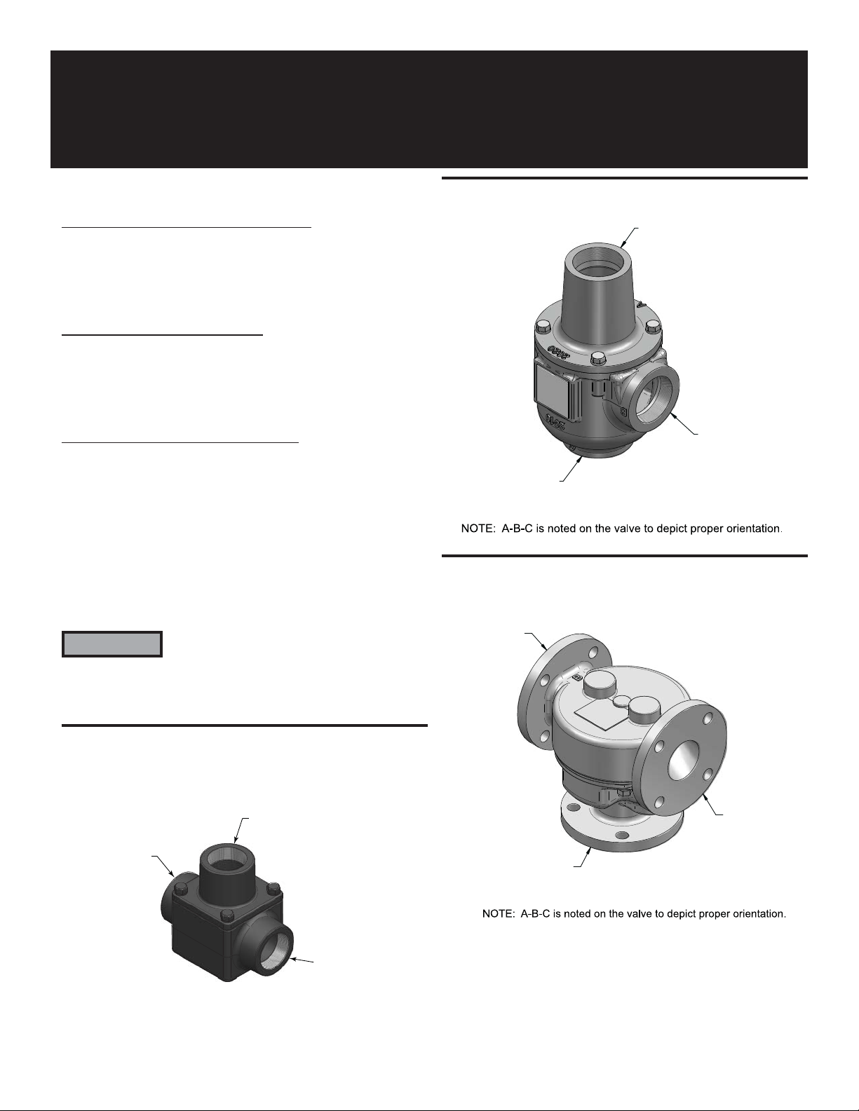
Figure 2_ 2" Valve
Figure 3_ 2 1/2" Valve
Figure 1_ 1 1/2" Valve
C = SYSTEM
RETURN
WATER
B = FROM BOILER
OUTLET
A = BLENDED
WATER
B = FROM
BOILER
OUTLET
A = BLENDED
WATER
C = SYSTEM
RETURN
WATER
B = FROM BOILER
OUTLET
NOTE: A-B-C is noted on the valve to depict proper orientation.
C = SYSTEM
RETURN
WATER
A = BLENDED
WATER
Page 2
2 of 8
Typical piping applications:
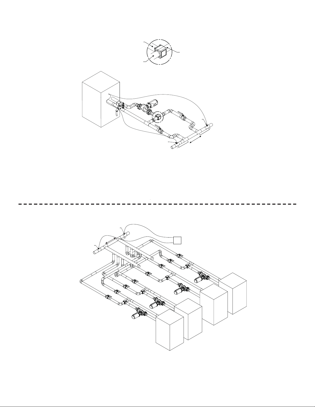
Figure 4_Primary/Secondary Piping of a Single Boiler - 1 1/2" Valve
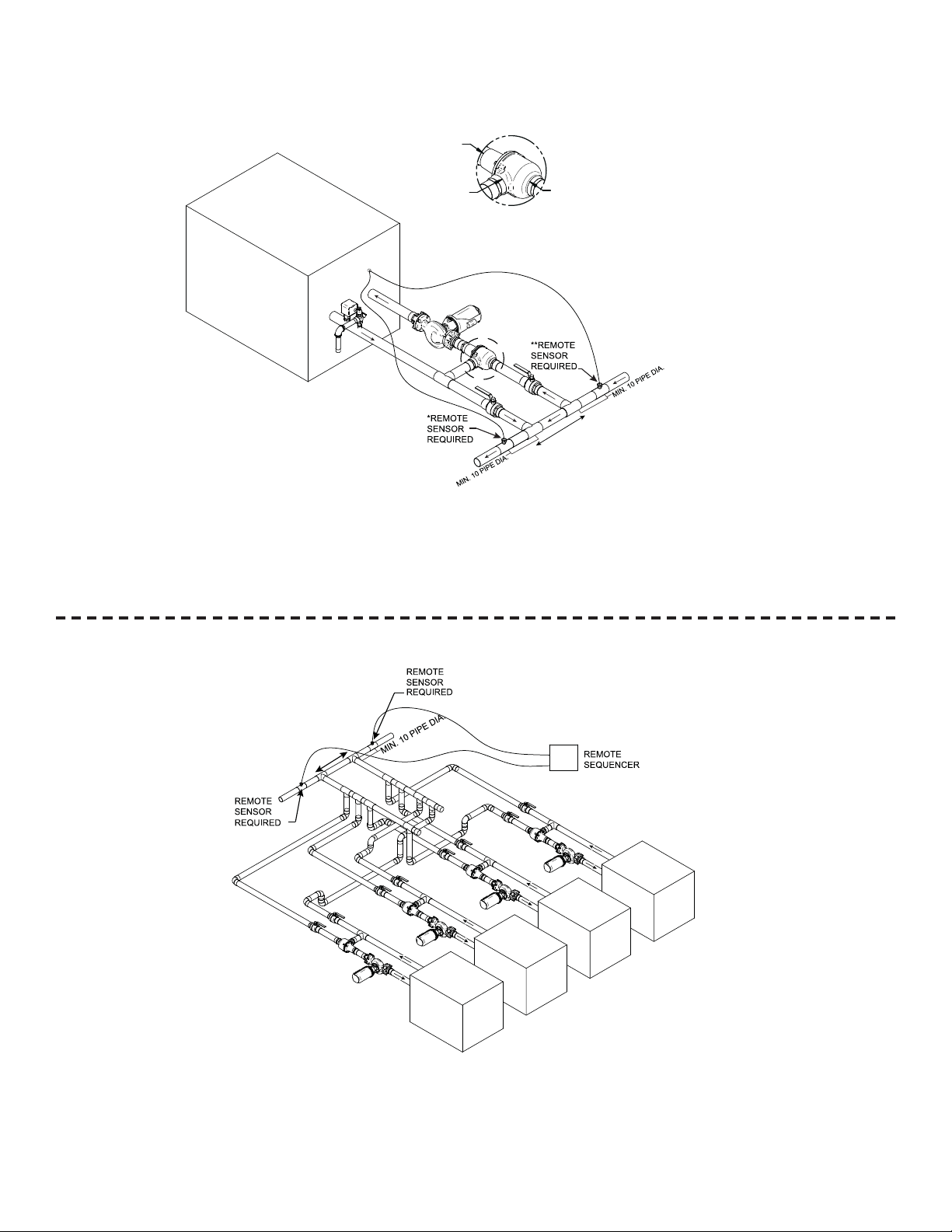
Figure 5_Primary /Secondary Piping of Multiple Boilers - 1 1/2" Valve for each boiler
INS7238 Rev C
A = BLENDED
WATER
C = SYSTEM
RETURN
B = FROM
BOILER
OUTLET
DETAIL
Note: Valve must be installed with proper port orientation.
Failure to observe port markings on the valve body prior to
installing the valve could result in damage to the unit.
WATER
*Best practice for Indoor/Outdoor reset.
**Best practice for set point operation.
DETAIL
*REMOTE
SENSOR
REQUIRED
MIN. 10 PIPE DIA.
**REMOTE
SENSOR
REQUIRED
NOT TO EXCEED 4 PIPE DIA.
OR A MAX. OF 12” APART
MIN. 10 PIPE DIA.
NOTES: 1) Unit(s) high limit must be set at max.
2) Inlet and outlet connections to the boiler are shown for reference only.
Actual connections may vary from those represented here. Consult the
Installation and Service Manual for actual locations.
3) Unit(s) pump should operate only during firing periods.
REMOTE
SENSOR
REQUIRED
REMOTE
SENSOR
REQUIRED
NOT TO EXCEED 4 PIPE DIA.
OR A MAX. OF 12” APART
MIN. 10 PIPE DIA.
REMOTE
SEQUENCER
NOTES: 1) Unit(s) high limit must be set at max.
2) Inlet and outlet connections to the boiler are shown for reference only.
Actual connections may vary from those represented here. Consult the
Installation and Service Manual for actual locations.
3) Unit(s) pump should operate only during firing periods.
Page 3
3 of 8
Typical piping applications (cont.):
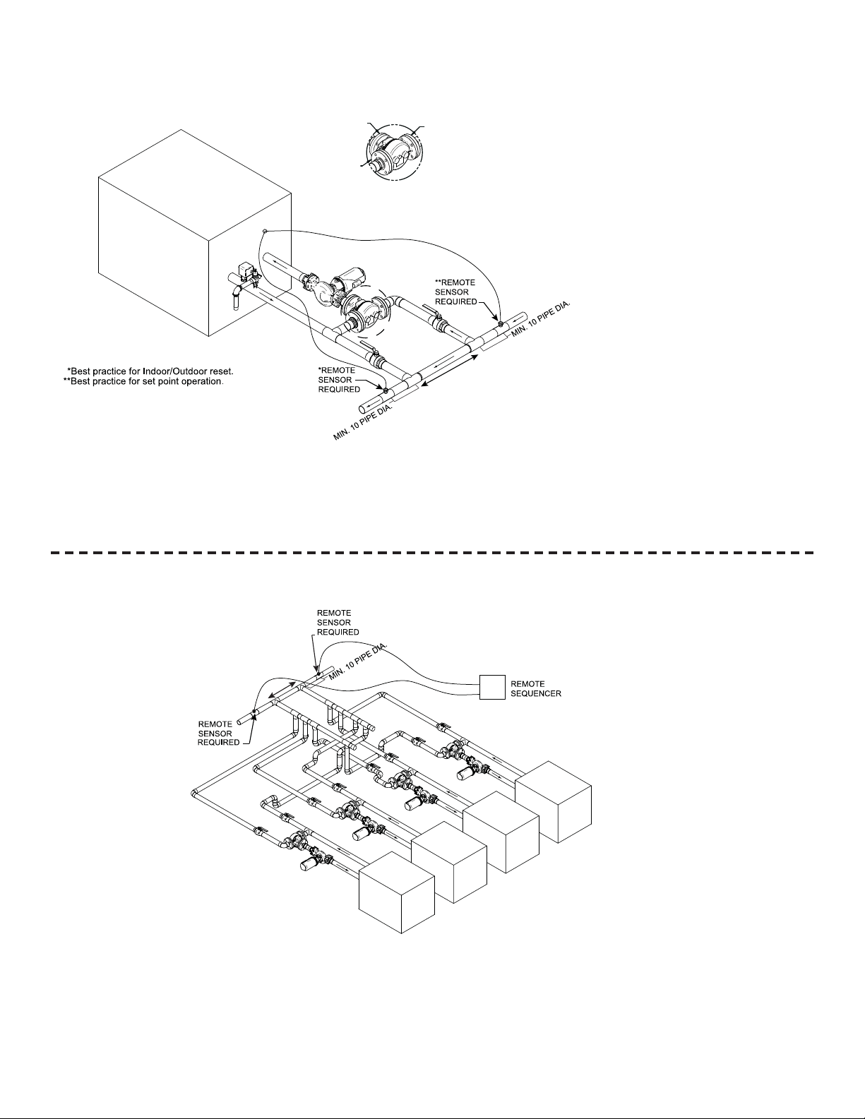
Figure 6_Primary /Secondary Piping of a Single Boiler - 2" Valve
Figure 7_Primary/Secondary Piping of Multiple Boilers - 2" Valve for each boiler
INS7238 Rev C
A = BLENDED
WATER
C = SYSTEM
RETURN
WATER
Note: Valve must be installed with proper port orientation.
Failure to observe port markings on the valve body prior to
installing the valve could result in damage to the unit.
NOT TO EXCEED 4 PIPE DIA.
OR A MAX. OF 12” APART
*Best practice for Indoor/Outdoor reset.
**Best practice for set point operation.
B = FROM
BOILER
OUTLET
DETAIL
DETAIL
NOTES: 1) Unit(s) high limit must be set at max.
2) Inlet and outlet connections to the boiler are shown for reference only. Actual connections may vary
from those represented here. Consult the Installation and Service Manual for actual locations.
3) Unit(s) pump should operate only during firing periods.
NOT TO EXCEED 4 PIPE DIA.
OR A MAX. OF 12” APART
NOTES: 1) Unit(s) high limit must be set at max.
2) Inlet and outlet connections to the boiler are shown for reference only. Actual connections may vary
from those represented here. Consult the Installation and Service Manual for actual locations.
3) Unit(s) pump should operate only during firing periods.
Page 4
Typical piping applications (cont.):
Figure 8_Primary/Secondary Piping of a Single Boiler - 2 1/2" Valve
Figure 9_Primary/Secondary Piping of Multiple Boilers - 2 1/2" Valve for each boiler
4 of 8
INS7238 Rev C
A = BLENDED
WATER
B = FROM
BOILER
OUTLET
DETAIL
C = SYSTEM
RETURN
WATER
Note: Valve must be installed
with proper port orientation. Failure to
observe port markings on the valve
body prior to installing the valve could
result in damage to the unit.
DETAIL
NOT TO EXCEED 4 PIPE DIA.
OR A MAX. OF 12” APART
NOTES: 1) Unit(s) high limit must be set at max.
2) Inlet and outlet connections to the boiler are shown for reference only. Actual connections may vary
from those represented here. Consult the Installation and Service Manual for actual locations.
3) Unit(s) pump should operate only during firing periods.
Page 5

Figure 11_2" LTV Valve - Up to 750,000 Btu/hr
Figure 12_2 1/2" LTV Valve - 990,000 Btu/hr and up
Figure 10_1 1/2" LTV Valve - 45,000 - 500,000 Btu/hr
5 of 8
INS7238 Rev C
A
C
5.250
B
3.750
TOP
PORT "C"
PORT "A"
PORT "B"
6.125
SIDE
Page 6
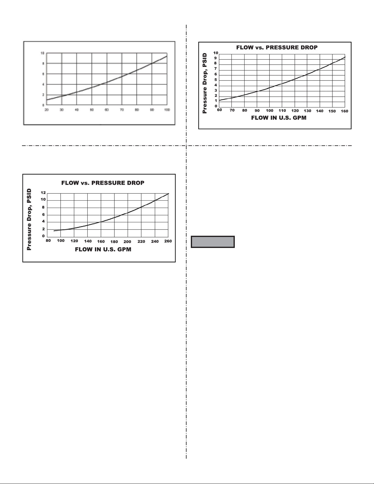
Figure 14_2" - Flow vs. Pressure Drop
Figure 15_2 1/2" - Flow vs. Pressure Drop
Figure 13_1 1/2" - Flow vs. Pressure Drop
6 of 8
INS7238 Rev C
Maintenance instructions
The LTV valve is maintenance free. It does not require regular
cleaning or calibration. In most installations, the 1-1/2" and 2"
valves are hard piped into place and do not afford access. The
2-1/2" valve has flanged connects which allows removal.
If the valve becomes unable to maintain a consistent inlet water
temperature of 125°F during steady state firing conditions, replace
the valve or the wax element inside the valve.
The recommended maximum high
temperature to the valve should be 175°F; the
absolute maximum is 195°F.
WARNING
FLOW vs. PRESSURE DROP
Pressure Drop, PSID
FLOW IN U.S. GPM
Page 7

7 of 8
INS7238 Rev C
Notes
Page 8

Revision Notes: Revision A (INS7238 Rev A)
reflects the addition of the 1 1/2" valve.
Revision B (INS7238 Rev B) reflects the
addition of the maintenance instructions.
Revision C (ECO C02335) reflects the revision
of FIG.’s. 1, 2, 3, 4, 6 & 8.
10/08 - Printed in U.S.A.
 Loading...