

Page 1

User Guide
LB-FEA800M
Rev.1.0
2005/1/27
Page 2

Page 3

1. Introduction
The LB-FEA800M is compact desktop size switches that are ideal solutions
for SOHO (Small Office or Home Office) network user. It provides wire-speed,
Fast Ethernet switching function that allows high-performance, low-cost
connection. The Switches feature a store-and-forward switching and it can
auto-learn and store source address on an 8K-entry MAC address table.
The Switches provides 8 switched auto-sensing 10/100 Mbps RJ-45 Ethernet
ports and features Auto MDI/MDIX function for each port. [In general, MDI
means connecting to another Hub or Switch while MDIX means connecting to
a workstation or PC. Therefore, Auto MDI/MDIX means that you can connect
to another Switch or workstation without changing non-crossover or crossover
cabling. ]
With there build-in Web-based Management, managing and configuring the
LB-FEA800M becomes easier. From cabinet management to port-level control
and monitoring, you can visually configure and manage your network via Web
Browser. Just click your mouse instead of typing command strings. However,
the LB-FEA800M can also be managed via Telnet, Console, or SNMP
Management.
Features
n 8 10/100BASE-TX intelligent switch
n Switch fabric up to 3.8Gbps
n Fully software feature for Layer 2 management switch
n IGMP support for Multi-media application
n Port Mirror supported
n Spanning Tree, SNMP, RMON supported
n Support Port-based VLAN
Page 4

RFC
, RFC 1757
RMON1, LANTECH Enterprise MIB, RFC 1215 Trap,
load distribution
Global System support 8 levels of priority and mapping
Port based VLAN, 802.1Q Tag VLAN, Protocol Type
Support 2 types of Query mode for Enable/Disable or
n IEEE802 .1Q VLAN, GVRP supported
n Support Class of Service
n Broadcast Storm filter supported
n Support Port Security
n IEEE802.3ad Port trunk with LACP supported
Software Feature
RFC 1157 SNMP, RFC 1213 MIB II, Bridge MIB,
1643 Ethernet Like, RFC 1493 Bridge MIB
SNMP
RFC 2674VLAN MIB
Management
Trunk
Class of Service
QoS
Web management (IE)
RS-232 console management (Rear side)
Telnet
IEEE 802.3ad Trunk with LACP for
control and fail over recover
Up to 4 ports per group, max 4 Groups
Global system supports 2 queues for Hi and Low priority
to Hi/Low priority queue for Class of Service
VLAN
VLAN, GVRP support
VLAN ID up to 4094, VLANs up to 256 groups
Support IGMP Snooping, supports 256 groups.
IP Multicast
Auto Query
2
Page 5
tatic MAC address lock, MAC Filter, Port
Use this feature to analysis port traffic for this switch. It
RFC 768 UDP, RFC 783 TFTP, RFC 791 IP, RFC792
C 854 TELNET Server/Client, RFC 1112
Support port s
Filter Database
Security
Port Mirror
supports max 8 ports.
Broadcast
None, 5%, 10%, 15%, 20%, 25%
Control
Spanning Tree IEEE802.1d support
RFC Standard
ICMP, RF
IGMP, RFC 2068 HTTP,
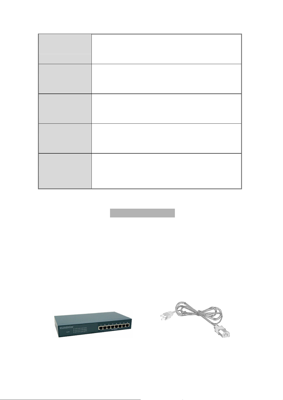
Package Contents
Unpack the contents of the LB-FEA800M and verify them against the checklist
below.
n LB-FEA800M
n Power Cord
n Four Rubber Feet
n RS-232 cable
n User Guide
LB-FEA800M Power Cord
Page 6

Rubber Feet RS-232 cable User Guide
Figure 1-2. Package Contents
Compare the contents of your LB-FEA800M package with the checklist above.
IF any item is missing or damaged, please contact your local dealer for
service.
Ethernet Switching Technology
Ethernet Switching Technology dramatically boosted the total bandwidth of a
network, eliminated congestion problems inherent with Carrier Sense multiple
access with Collision Detection (CSMA/CD) protocol, and greatly reduced
unnecessary transmissions.
This revolutionized networking. First, by allowing two-way, simultaneous
transmissions over the same port (Full-duplex), which essentially doubled the
bandwidth. Second, by reducing the collision domain to a single switch-port,
which eliminated the need for carrier sensing. Third, by using the
store-and-forward technology’s approach of inspecting each packet to
intercept corrupt or redundant data, switching eliminated unnecessary
transmission that slow the network. By employing address learning, which
replaced the inefficient receiving port.
Auto-negotiation regulates the speed and duplex of each port, based on the
capability of both devices. Flow-control allows transmission from a 100Mbps
node to a 10Mbps node without loss of data. Auto-negotiation and flow-control
may require disablement for some networking operations involves legacy
equipment. Disabling the auto-negotiation is accomplished by fixing the speed
or duplex of a port.
4
Page 7

Ethernet Switching Technology supplied higher performance at costs lower
than other solutions. Wider bandwidth, no congestion, and the reduction in
traffic is why switching is replacing expensive routers and inefficient hubs as
the ultimate networking solution. Switching brought a whole new way of
thinking to networking.
Page 8

Management Methods
The LB-FEA800M series supports following management methods:
n Console and Telnet Management
n Web-based Management
n SNMP Network Management
Console and Telnet Management
Console Management is done through the RS-232 Console Port. Managing
the LB-FEA800M in this method requires a direct connection between PC and
the 8TP+1Fiber Management Switch. While Telnet management is done over
the network. Once the LB-FEA800M is on the network, you can use Telnet to
Log in and change the configuration.
Web-based Management
The Switch provides an embedded HTML web site residing in flash memory. It
offers advanced management features and allow users to manage the
LB-FEA800M from anywhere on the network through a standard browser such
as Microsoft Internet Explorer.
SNMP Network Management
SNMP (Simple Network Management Protocol) provides a means to monitor
and control network device, and to manage configurations, statistic collection,
performance, and security.
6
Page 9
2. Hardware Description
This section mainly describes the hardware of the LB-FEA800M.
Physical dimensions
The physical dimensions of the LB-FEA800M is 250mm x 133mm x 37mm (L
x W x H)
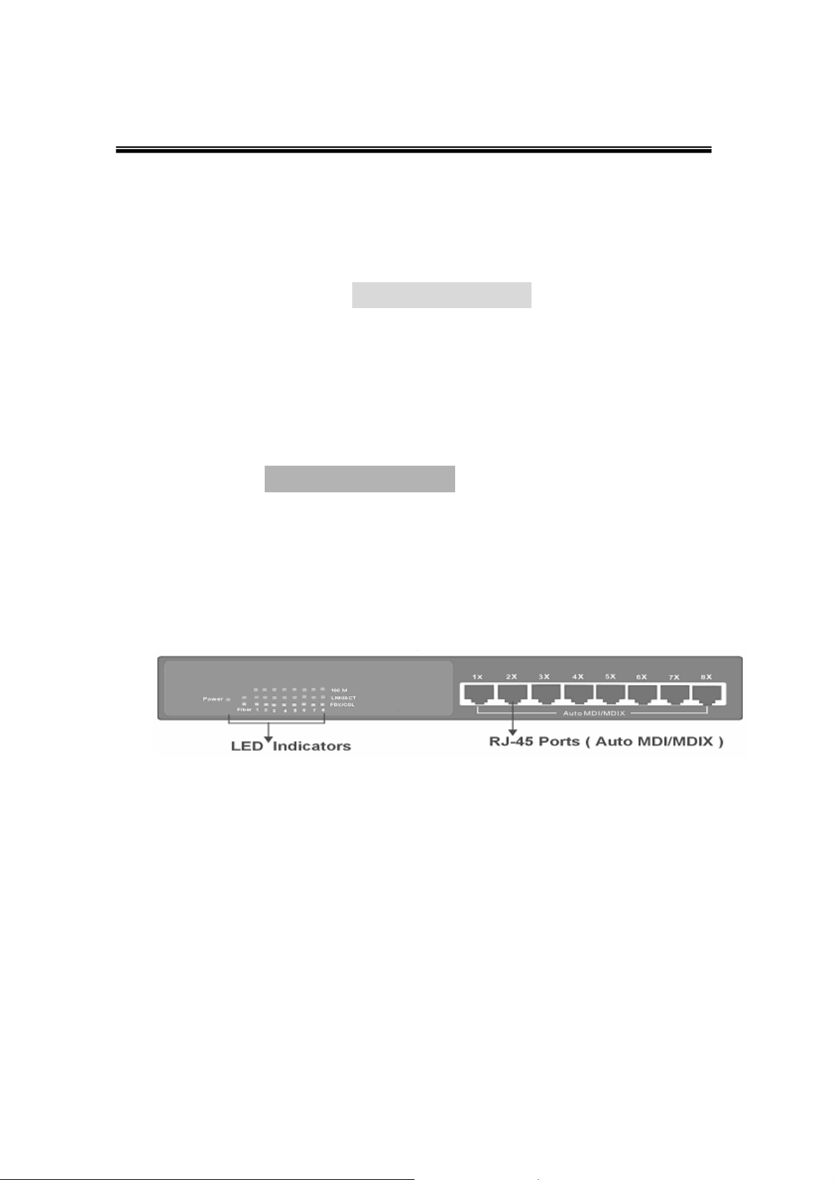
Front Panel
The Front Panel of the LB-FEA800M consist of 8x auto-sensing 10/100Mbps
Ethernet RJ-45 ports (automatic MDI/MDIX) and the LED indicators are also
located on the frond panel of the switch.
Figure 2-1. The Front Panel of theLB-FEA800M
n RJ-45 Ports (Auto MDI/MDIX): 8x 10/100 auto- sensing for 10Base-T or
100Base-TX connections.
[In general, MDI means connecting to another Hub or Switch while MDIX
means connecting to a workstation or PC. Therefore, Auto MDI/MDIX
means that you can connect to another Switch or workstation without
changing non-crossover or crossover cabling. ]
Page 10
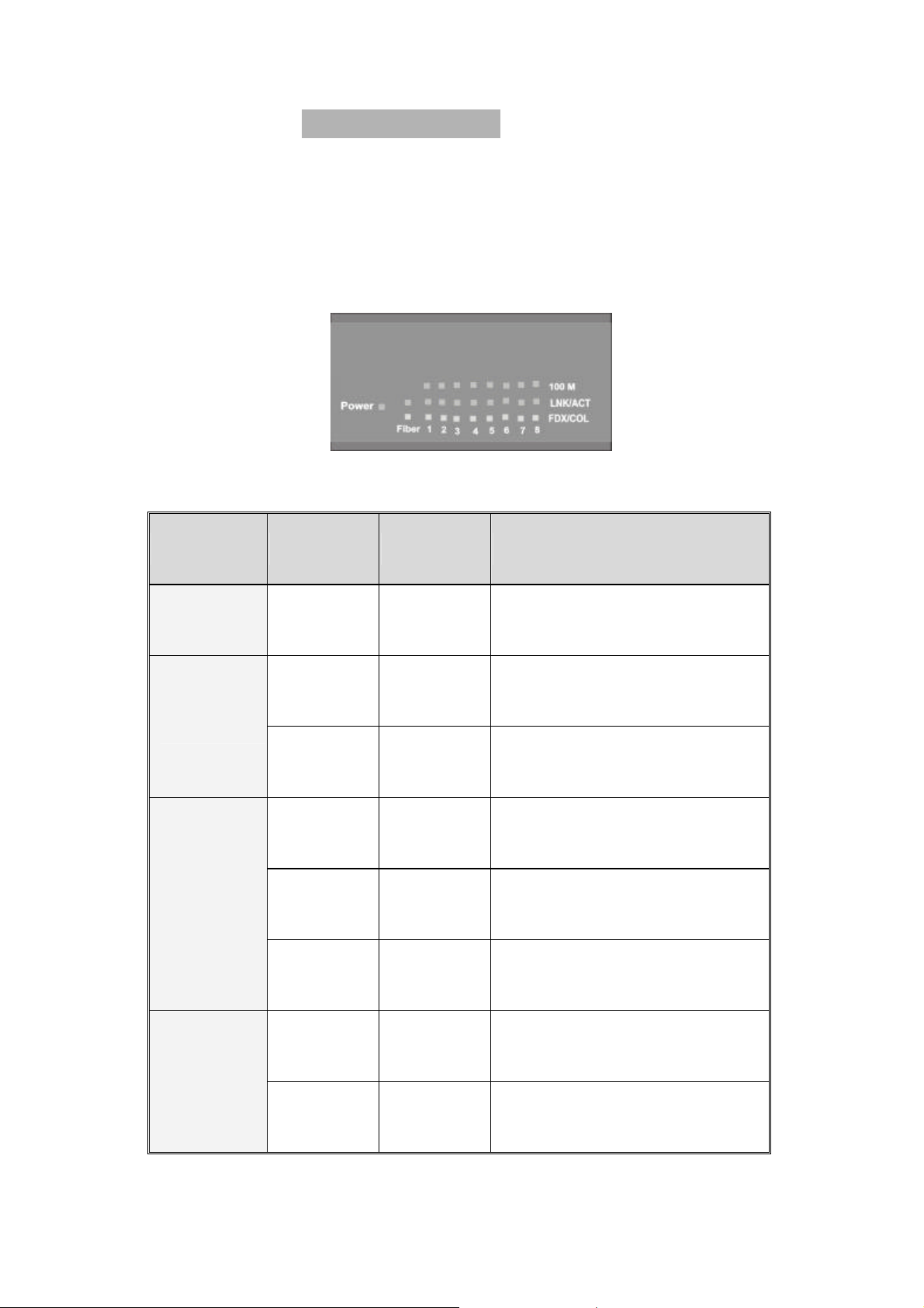
LED Indicators
There are three LED-Indicators (100M, LNK/ACT, FDX/COL) for each UTP
port. The following table provides descriptions of the LED statuses and
meaning. They provide a real-time indication of systematic operation status.
Figure 2-2. LED Indicators
LED Status Color Description
Power
On Green Power On
The port is operating at the
On Green
speed of 100Mbps.
100M
In 10Mbps mode or no
Off
device attached
The port is successfully
On Green
connecting with the device.
The port is receiving or
LNK /ACT
Blinks Green
transmitting data.
Off No device attached.
The port is operating in
FDX /COL
On Orange
Full-duplex mode.
Collision of Packets occurs
Blinks Orange
in the port.
8
Page 11
Half-duplex mode or no
Off
device attached.
Table 2-1. The description of LED Indicator
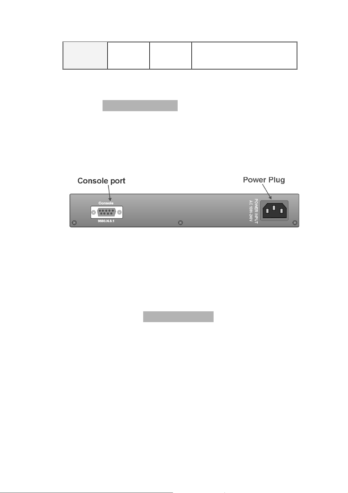
Rear Panel
The Console port and 3-pronged power plug are located at the Rear Panel of
the LB-FEA800M as shown in Figure 2-3. The Switches will work with AC in
the range 100-240V AC, 50-60Hz.
Figure 2-3 The Rear Panel of the LB-FEA800M
Console Port: Console management can be done through the Console Port.
It requires a direct connection between the Switch and an end station (PC) via
a RS-232 cable.
Desktop Installation
Set the switch on a sufficiently large flat space with a power outlet nearby. The
surface where you put your Switch should be clean, smooth, level, and sturdy.
Make sure there is enough clearance around the Switch to allow
attachment of cables, power cord and air circulation.
Attaching Rubber Feet
1. Make sure mounting surface on the bottom of the Switch is grease and
dust free.
Page 12
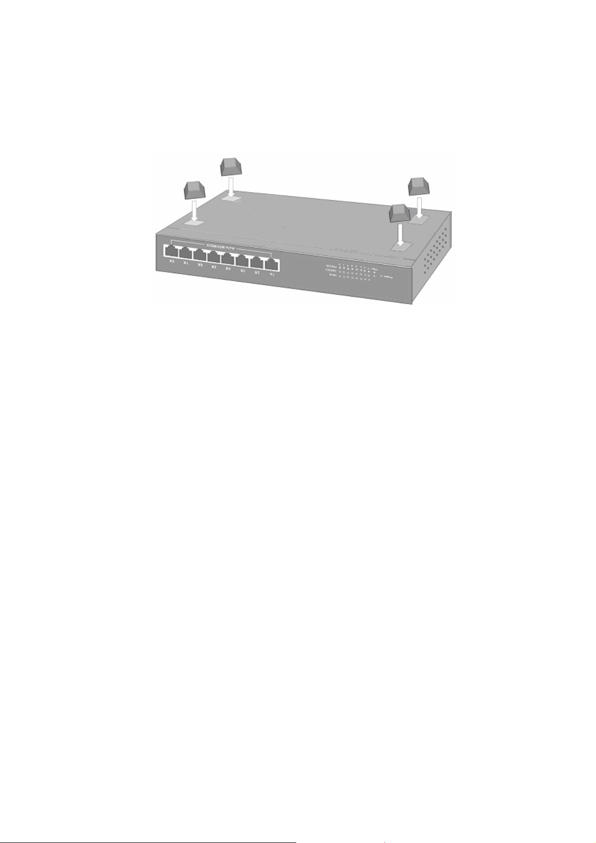
2. Remove adhesive backing from your Rubber Feet.
3. Apply the Rubber Feet to each corner on the bottom of the Switch. These
footpads can prevent the Switch from shock/vibration.
Figure 2-4. Attaching Rubber Feet to each corner on the bottom of the Switch
Power On
Connect the power cord to the power socket on the rear panel of the Switch.
The other side of power cord connects to the power outlet. Check the power
indicator on the front panel to see if power is properly supplied.
10
Page 13
3. Network Application
This section provides you a few samples of network topology in which the
Switch is used. In general, the LB-FEA800M is designed to be used as a
desktop or segment switch.
Desktop Application
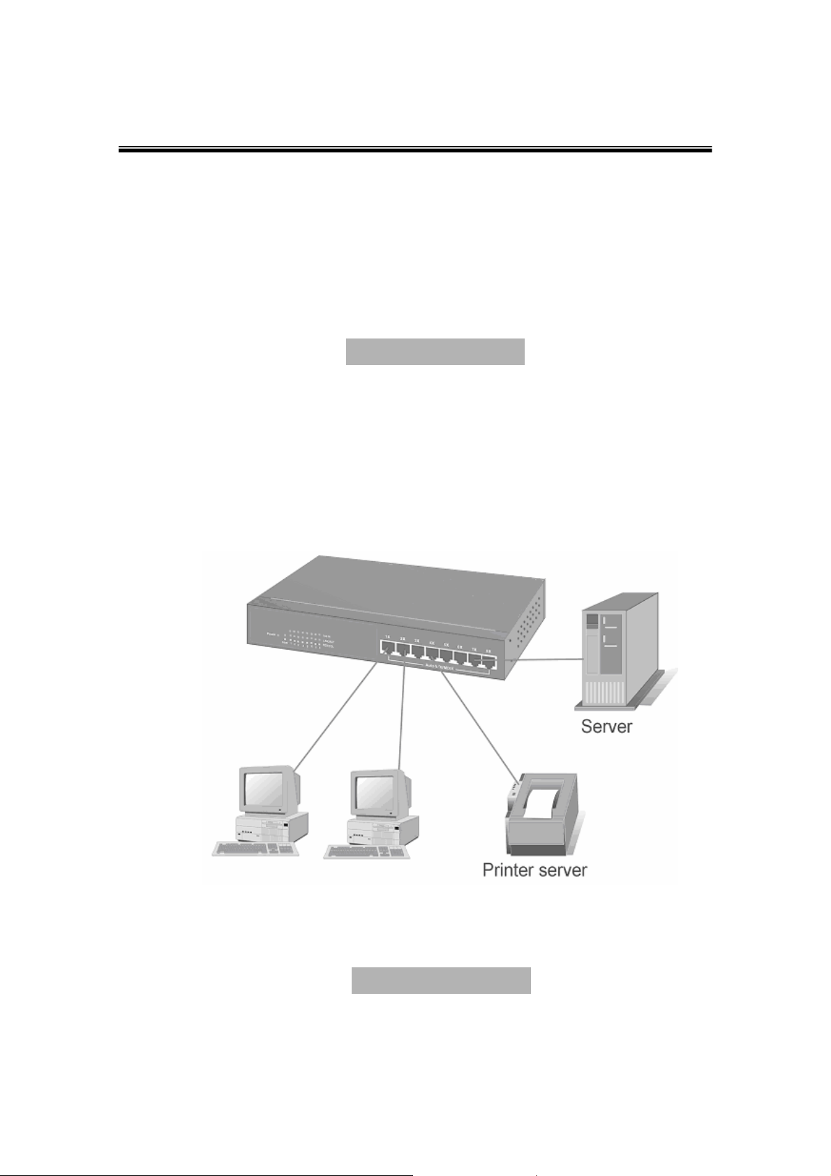
The LB-FEA800M series are designed to be a desktop size switch that is an
ideal solution for small workgroup. The Switch can be used as a standalone
switch to which personal computers, server, printer server are directly
connected to form small workgroup.
Figure 3-1. Desktop Application
Segment Application
For enterprise networks where large data broadcast are constantly processed,
Page 14
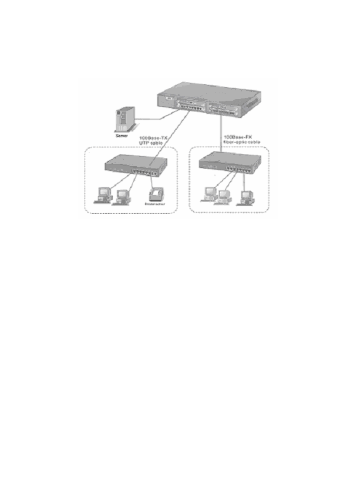
this switch is suitable for department user to connect to the corporate
backbone.
Figure 3-2 Segment Application
You can use the LB-FEA800M to connect PCs, workstations, and servers to
each other by connecting these devices directly to the Switch. All the devices
in this network can communicate with each other. Connecting servers to the
backbone switch allow other users to access the server’s data.
The Switch automatically learns node address, which are subsequently used
to filter and forward all traffic based on the destination address. You can use
any of the RJ-45 port of the LB-FEA800M to connect with another Switch or
Hub to interconnect each of your small-switched workgroups to form a larger
switched network.
12
Page 15
4. Network Configuration
This Section explains how to configure console management via a direct
connection to the console port of the LB-FEA800M.
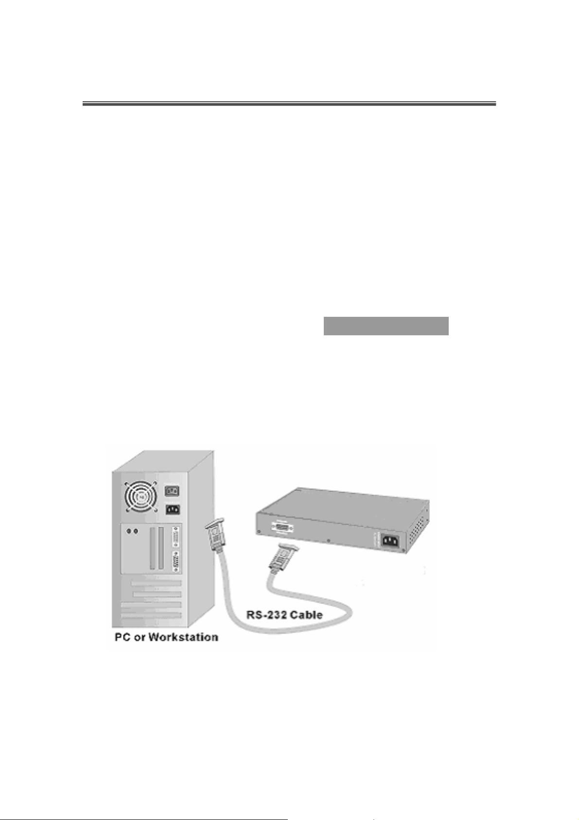
Console management involves the administration of the Switch via a direct
connection to the RS-232 console port. This port is a female DB-9 connector.
From the main menu of the console program, user has access to manage the
functions of the Switch.
Connecting to the Console Port
Use the supplied RS-232 cable to connect a terminal or PC to the console port.
The terminal or PC to be connected must support the terminal emulation
program.
Figure 4-1. Connecting the Switch to a terminal via RS-232 cable
After the connection between Switch and PC is finished, turn on the PC and
run a terminal emulation program or Hyper Terminal to match the following
default characteristics of the console port:
Page 16
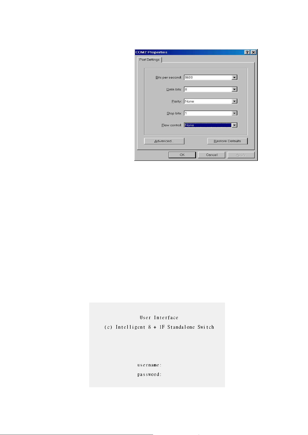
Baud Rate: 9600 bps
Data Bits: 8
Parity: none
Stop Bit: 1
Control flow: None
Figure 4-2. The settings of communication parameters
After you have finished parameter settings, press “ Enter “ Key and the Main
Menu of console management appears.
Console – Menu
1. The switch also provide a serial interface to manage and monitor the
switch, user can follow the Console Port Information provide by web to
use windows HyperTerminal program to link the switch.
2. You can type user name and password to login. The default user name is
“ root”; the default password is “root ”.
14
Page 17
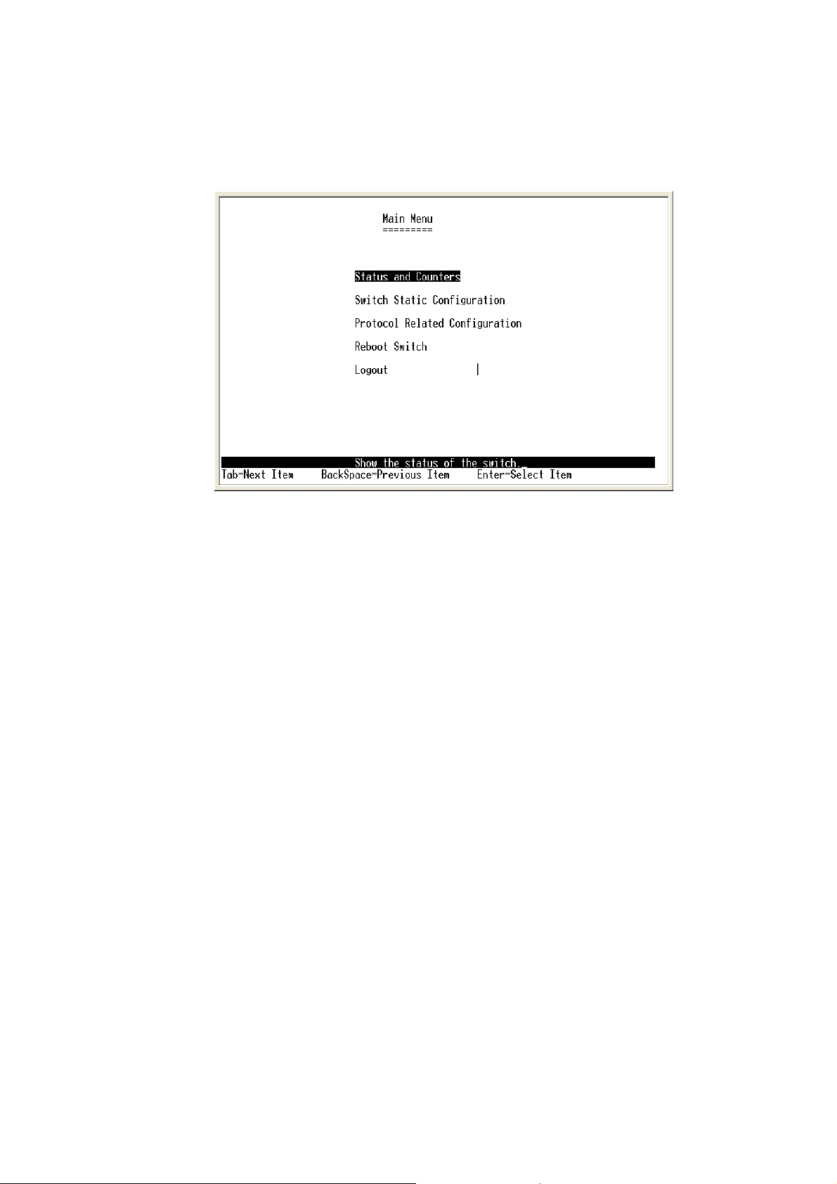
Main Menu
There are five items for selected as follows.
n Status and Counters: Show the status of the switch.
n Switch Static Configuration: Configure the switch.
n Protocol Related Configuration: Configure the protocol function.
n Reboot Switch: Restart the system or reset switch to default
configuration.
n Logout: Exit the menu line program.
<Control Key>
The control key as follow provided in all menus:
n Tab: Move the vernier to next item.
n Backspace: Move the vernier to previous item.
n Enter: Select item.
n Space: Toggle selected item to next configure.
Status and Counters
Page 18

You can press the key of Tab or Backspace to choose item, and press Enter
key to select item.
Port Status
This page display every port status
n Type: Display the port type.
n Enabled: Display the port is enabled or disable depended on user setting.
Enable will be display “Yes”; disable will be display “No”.
n Status: Display the port is link or no link, “Down” is no link, and “Up” is
link.
n Mode: Display the port speed and duplex.
n FlowCtrl: Display the flow control status is enable or disable mode.
16
Page 19
Actions->
You can press the key of Tab or Backspace to choose action menu, and
press Enter key to select item
<Quit>: Exit the page of port status, and return to previous menu.
<Previous Page>: Display previous page.
<Next page>: Display next page.
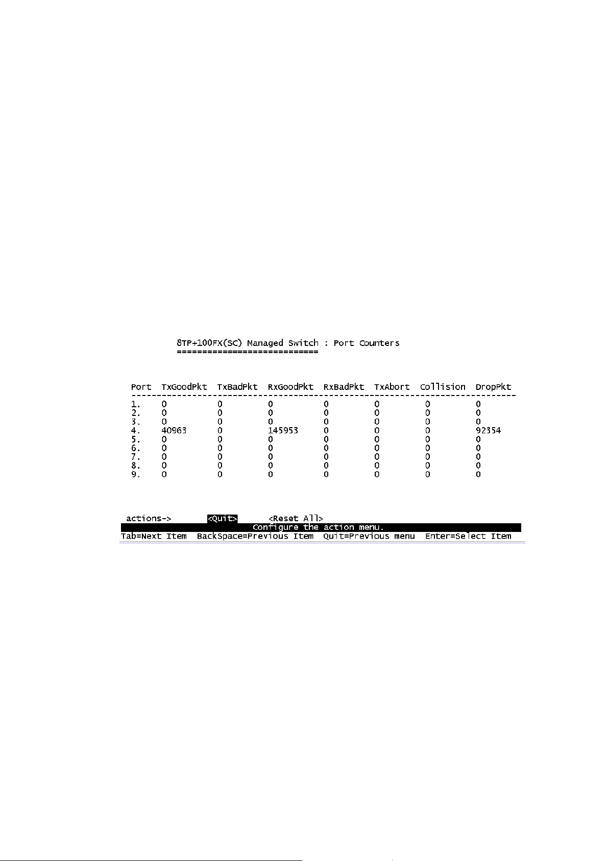
Port Counters
The following information provides a view of the current status of the unit.
Actions->
You can press the key of Tab or Backspace to choose action menu, and
press Enter key to select item
<Quit>: Exit the page of port status, and return to previous menu.
<Reset All>: Set all count to 0.
<Previous Page>: Display previous page.
<Next page>: Display next page.
Page 20
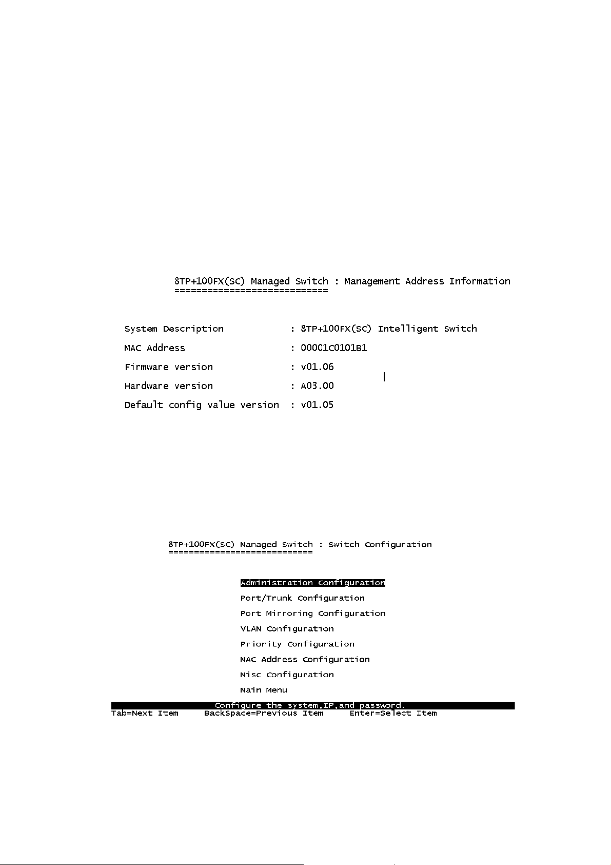
4-2-3. System Information
System Description: Display the name of device type.
MAC Address: The unique hardware address assigned by manufacturer.
Firmware Version: Display the switch’s firmware version.
Hardware Version: Display the switch’s Hardware version.
Default configure value version: Display write to default EEPROM value
version.
Switch Static Configuration
You can press the key of Tab or Backspace to choose item, and press Enter
key to select item
18
Page 21
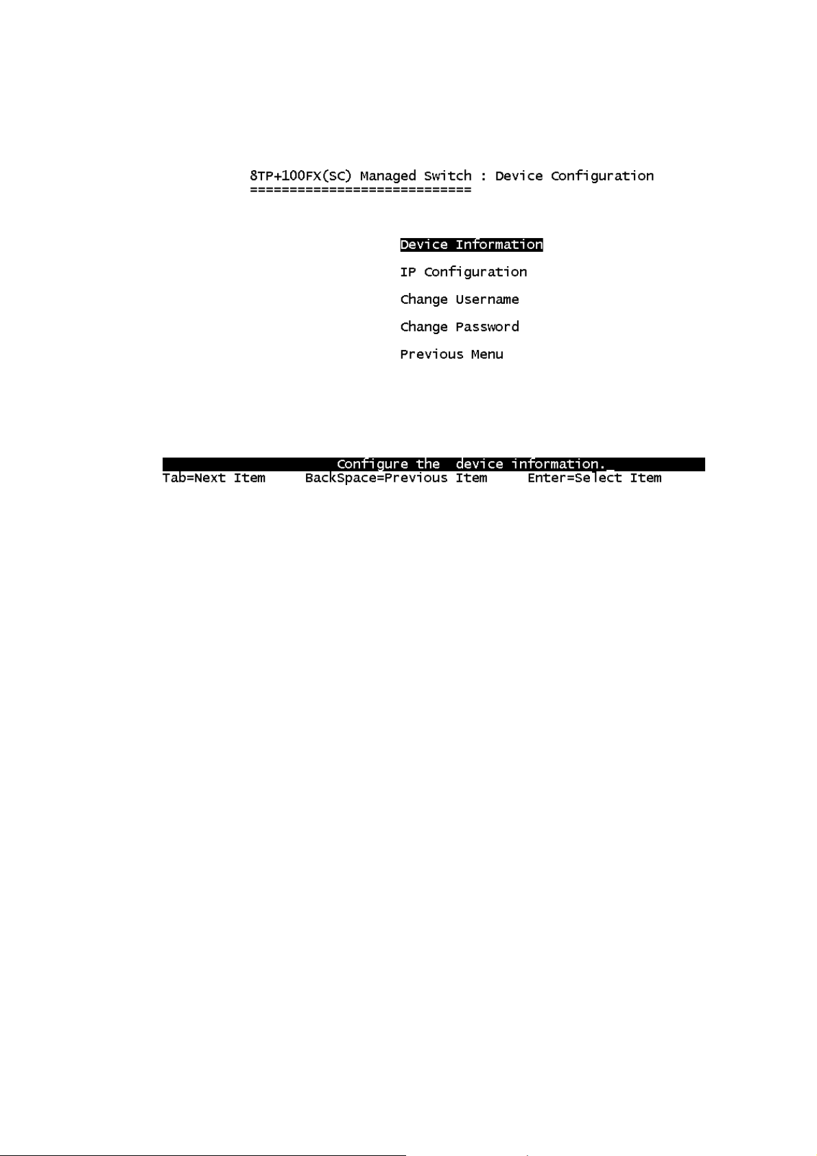
Administration Configuration
Device Information
This page provide user to configure the device information.
Actions->
<Edit>: Configure all items. Finished configure press Backspace to go back
action menu line.
<Save>: Save all configure value.
<Quit>: Exit the page of device information and return to previous menu.
Page 22
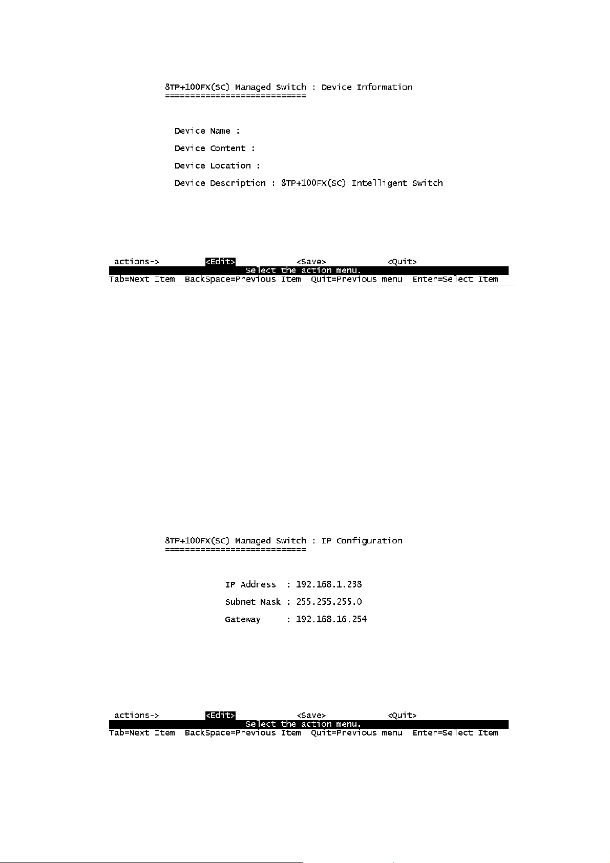
IP Configuration
User can configure the IP setting and fill in the new value.
Actions->
<Edit>: Configure all items. Finished configure press ESC to go back action
menu line.
<Save>: Save all configure value.
<Quit>: Exit the page of IP configuration and return to previous menu.
Note: Always restart the computer after finishing the setup.
20
Page 23
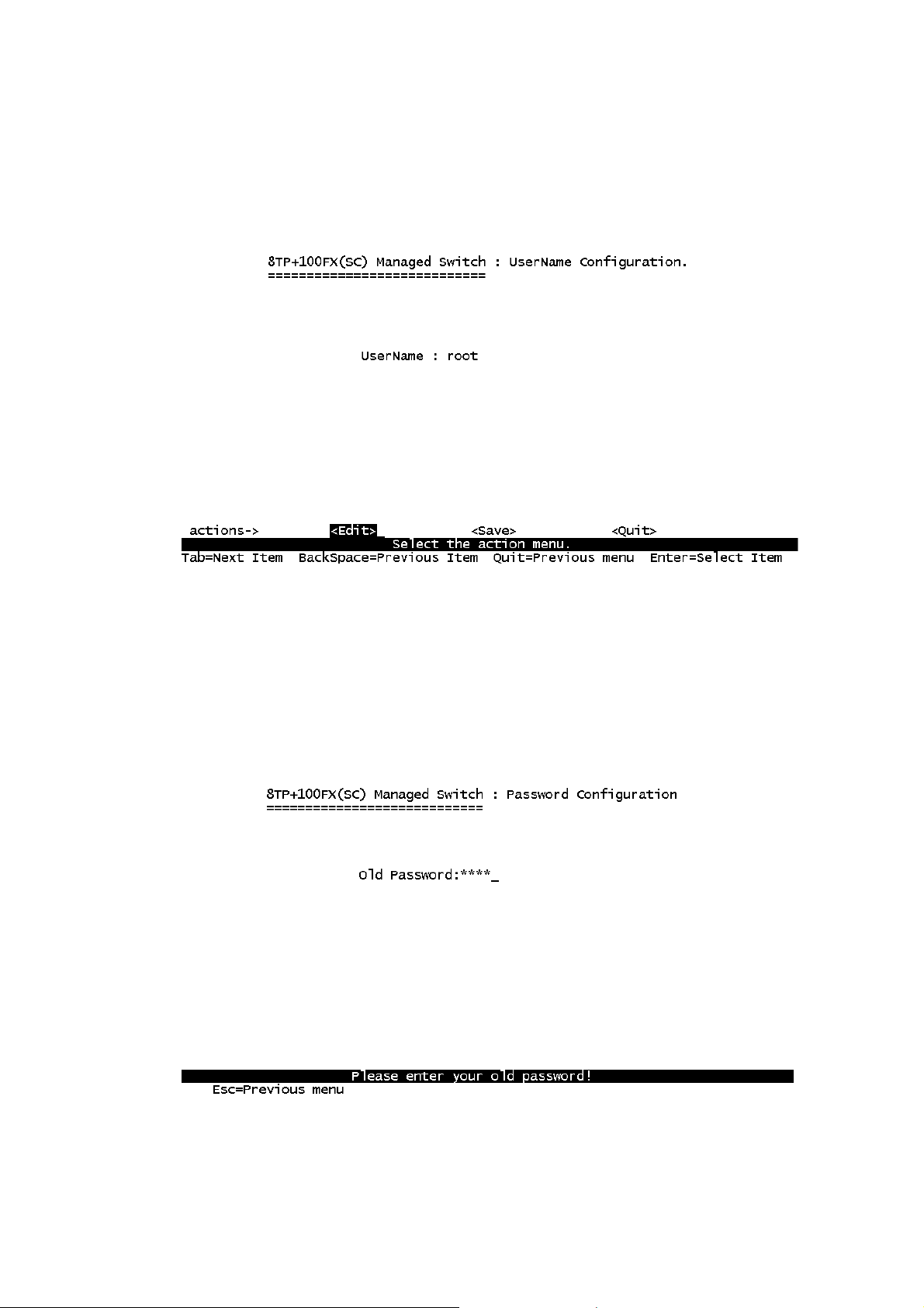
Change Username
Use this page; user can change web management user name.
Change Password
Use this page; user can change web management user password.
Page 24
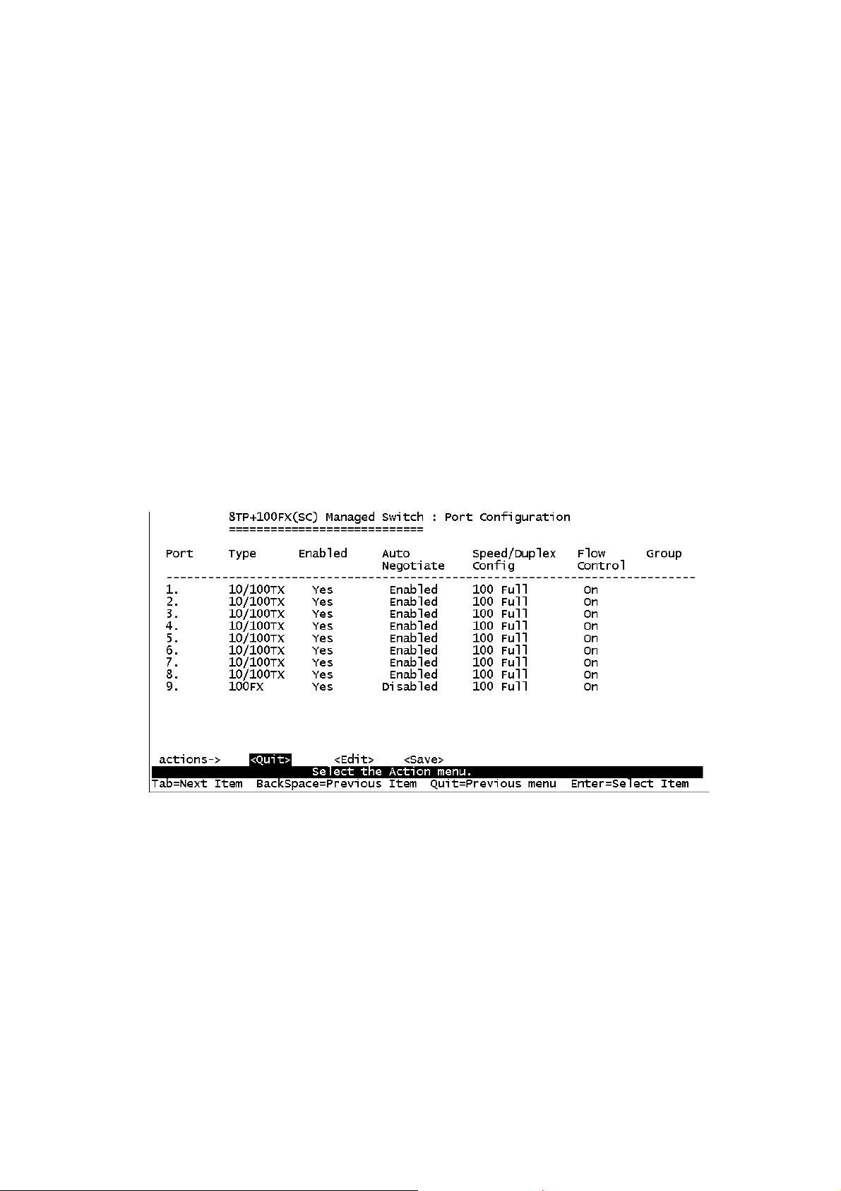
Port / Trunk Configuration
This page can change every port status and configure trunk group. Press TAB
key to change configure of per item.
1. Enabled: User can disable or enable this port control.
2. Auto Negotiate: User can set auto negotiation is enable or disable of per
port.
3. Speed/Duplex Config: User can set 100Mbps or 10Mbps speed on port
1~port 8, only 100Mbps on port 9, and set full-duplex or half-duplex mode.
4. Flow Control: User can set flow control function is enable or disable.
5. Group: User can set trunk group for port1~prot8. There are four trunk
groups to provided configure.
Actions->
<Quit>: Exit the page of port configuration and return to previous menu.
<Edit>: Configure all items. Finished configure press ESC to go back action
menu line.
<Save>: Save all configure value.
<Previous Page>: Return to previous page to configure.
<Next page>: Go to next page to configure.
22
Page 25

Port Mirroring Configuration
The port mirroring is a method for monitor traffic in switched networks. Traffic
through ports can be monitored by one specific port. That is traffic goes in or
out monitored ports will be duplicated into monitoring port. Press Space key to
change configure of per item.
1. Analysis State: Type YES or NO for port-morrioing function.
2. Mirroring Port: It’s mean mirror port can be used to see all monitor port
traffic.
3. Source Port: The ports you want to monitor. All monitor port traffic will be
copied to sniffer port. You can select max 9 monitor ports in the switch.
User can choose want to monitored RX frames only or TX frames only or
both RX and TX frame from the port at Action item.
Actions->
<Quit>: Exit the page of port monitoring configuration and return to previous
menu.
<Edit>: Configure all items. Finished configure press ESC to go back action
menu line.
<Save>: Save all configure value.
<Previous Page>: Return to previous page to configure.
Page 26

<Next page>: Go to next page to configure.
VLAN Configuration
VLAN Configure
1. PVID (Port VID): Set the port VLAN ID that will be assigned to untagged
traffic on a given port. This feature is useful for accommodating devices
that you want to participate in the VLAN but that don’t support tagging.
Only one untagged VLAN is allowed per port.
2. Ingress Filter 1: It’s matches that Ingress Filtering Rule 1 on web.
Forward packets only with VID matching this port’s configured VID. Press
Space key to choose forward or drop the frame that VID not matching this
port’s configured VID.
3. Ingress Filter 2: It matches that Ingress Filtering Rule 2 on web. Drop
untagged frame.
Press Space key to choose drop or forward the untagged frame.
24
Page 27
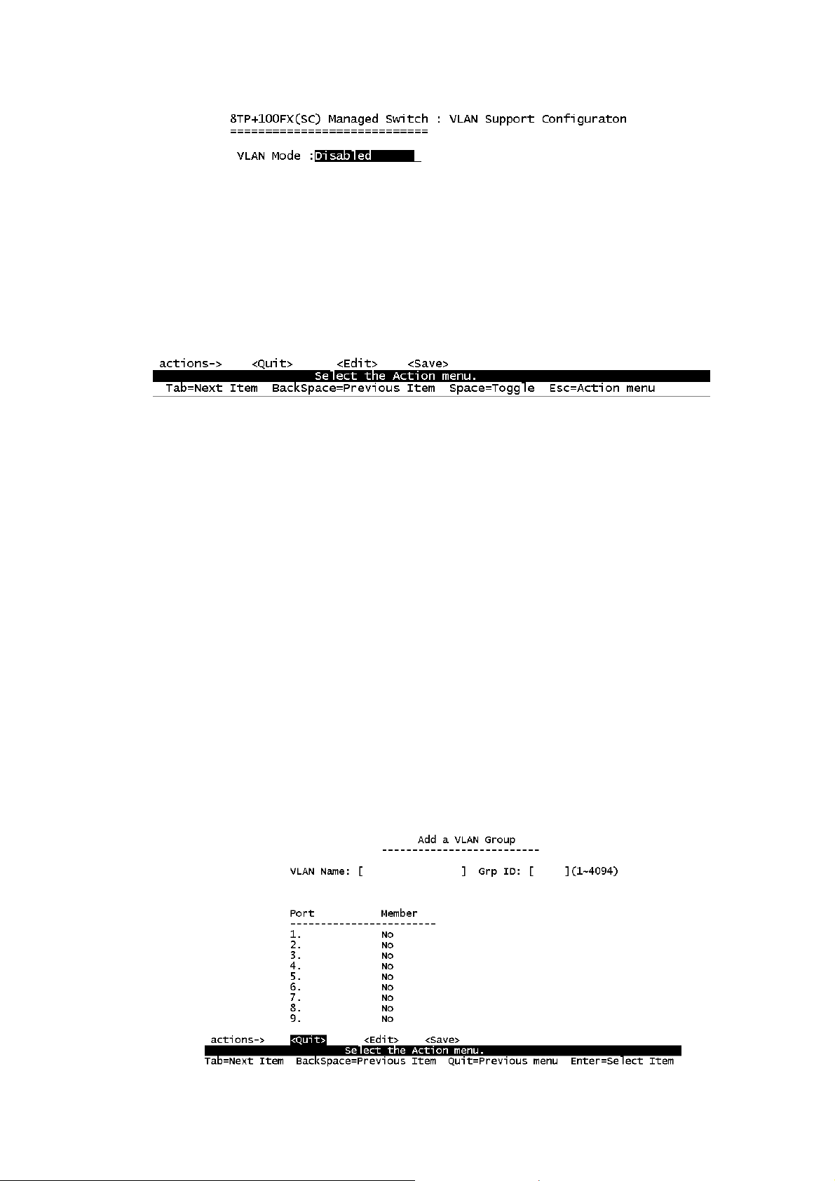
Create a VLAN Group
Create a VLAN and add tagged /untagged member ports to it.
1. VLAN Name: Type a name for the new VLAN.
2. VLAN ID: Type a VID (between 2~4094). The default is 1.
3. Protocol VLAN: Press Space key to choose protocols type.
4. Mode: Press Space key to choose VLAN member. There are three types
to select as 802.1Q, 802.1Q with GVRP and PortBase.
n Untagged: the member port is un-tagged port.
n Tagged: the member port is tagged port.
n NO: The port is not member of this VLAN group.
Page 28

Actions->
<Quit>: Exit this page and return to previous menu.
<Edit>: Configure all items. Finished configure press ESC to go back action
menu line.
<Save>: Save all configure value.
<Previous Page>: Return to previous page to configure.
<Next page>: Go to next page to configure.
Edit / Delete a VLAN Group
In this page, user can edit or delete a VLAN group.
1. Press <Edit> or <Delete> item.
2. Choose the VLAN group that you want to edit or delete and then press
enter.
3. User can modify the protocol VLAN item and the member port is tagged or
un-tagged and remove some member ports from this VLAN group.
4. After edit or delete VLAN, press <Save> key to save all configures value.
NOTE: 1.The VLAN Name and VLAN ID cannot modify.
2.The default VLAN can’t be deleting.
Priority Configuration
26
Page 29
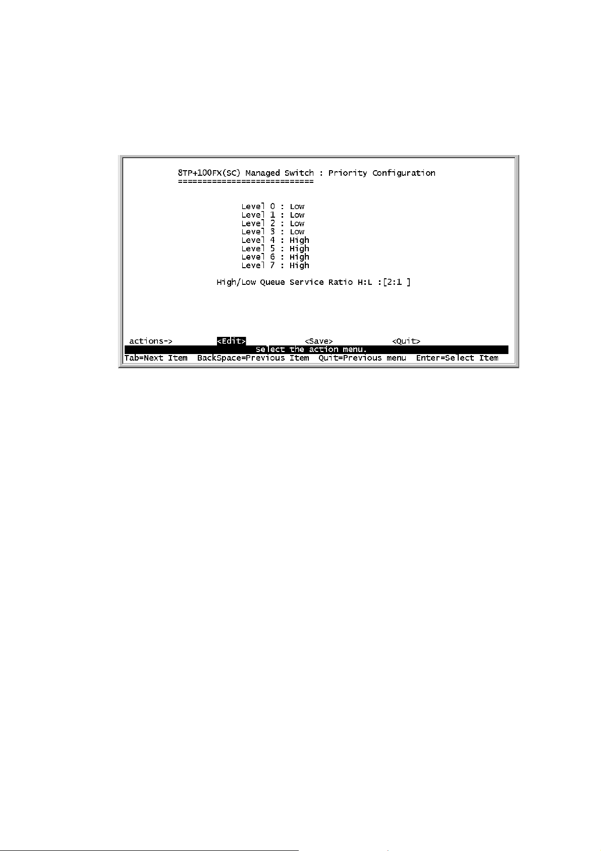
1. There are 0~7 priority level can map to high or low queue.
2. High/Low Queue Service Ration H:L : User can select the ratio of high
priority packets and low priority packets.
Actions->
<Edit>: Configure all items. Finished configure press ESC to go back action
menu line.
<Save>: Save all configure value.
<Quit>: Exit this page and return to previous menu.
n First In First Out: The sequence of packets sent is depend on arrive
order.
n High to Low: The high priority packets sent before low priority packets.
n Ratio: Select the preference given to packets in the switch's high-priority
queue.
These options represent the number of high priority packets sent before one
low priority packet is sent. For example, 2 High: 1 Low means that the switch
sends 2 high priority packets before sending 1 low priority packet.
Page 30
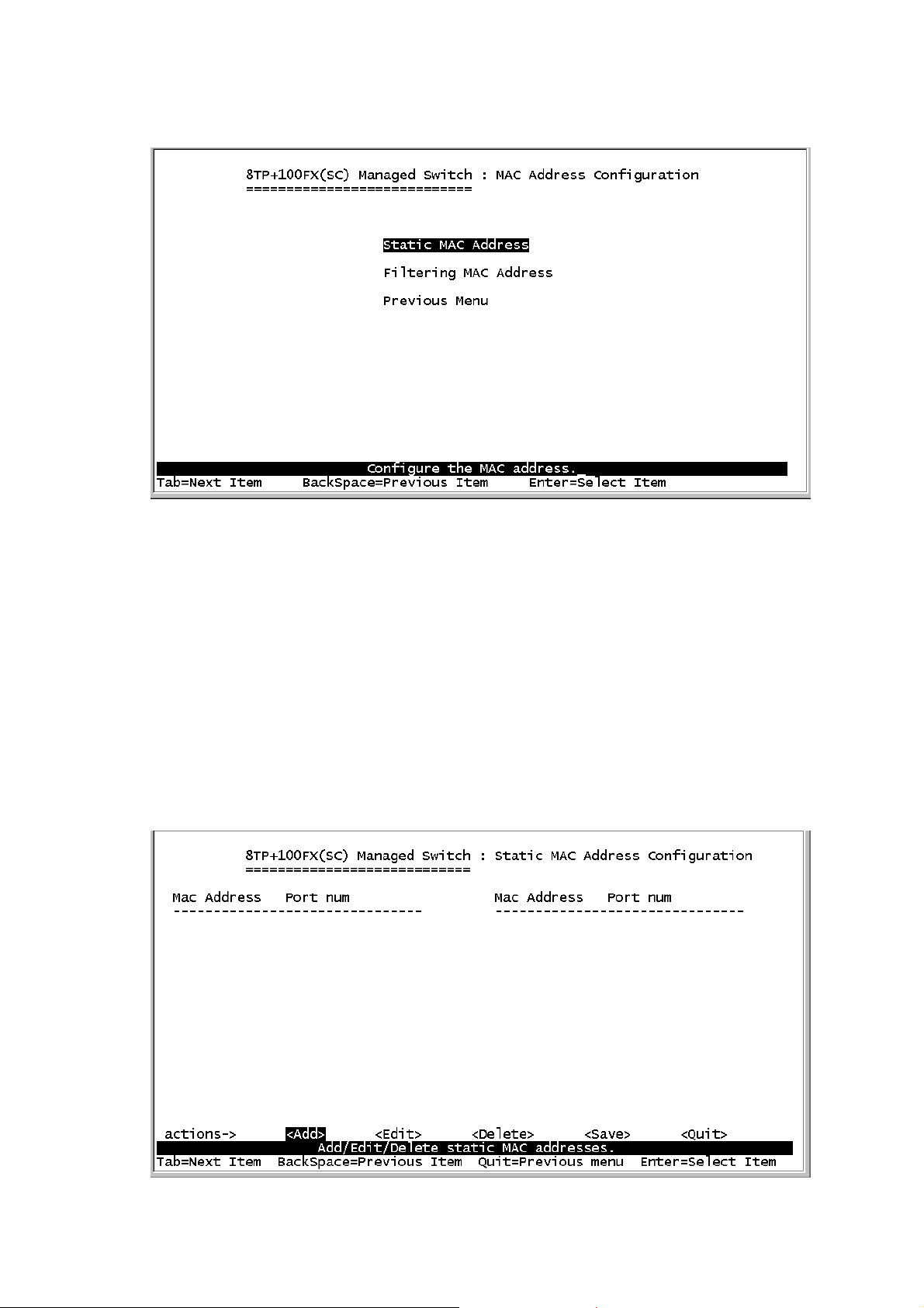
4-3-6.MAC Address Configuration
4-3-6-1.Static MAC Address
When you add a static MAC address, it remains in the switch's address
table, regardless of whether the device is physically connected to the
switch. This saves the switch from having to re-learn a device's MAC
address when the disconnected or powered-off device is active on the
network again.
In this page user can add / modify / delete a static MAC address.
28
Page 31

Add static MAC address
1.Press <Add> --> <Edit> key to add a static MAC address.
2.Enter the MAC address to and from which the port should
permanently forward traffic, regardless of the devices network activity.
3.In the Port num item, enter the port number.
4.If tag-based (802.1Q) VLAN are set up on the switch, static addresses
are associated with individual VLANs. Type the VID to associate with
the MAC address.
5. Press ESC to go back action menu line, and then select <Save> to
save all configure value.
Edit static MAC address
1.Press <Edit> key to modify a static MAC address.
2.Choose the MAC address that you want to modify and then press
enter.
3.Press <Edit> key to modify all the items.
4.Press ESC to go back action menu line, and then select <Save> to
save all configure value.
Delete static MAC address
1.Press <Delete> key to delete a static MAC address.
2.Choose the MAC address that you want to delete and then press
enter.
3.After delete static MAC address, you have to press <Save> to
complete the deleting operation.
Page 32
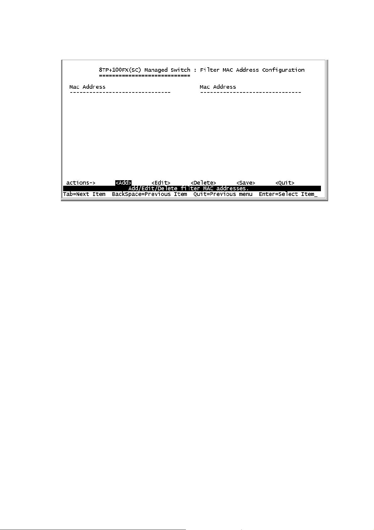
4-3-6-2.Filtering MAC Address
Edit Filtering MAC address
1.Press <Edit> key to modify a static Filtering address.
2.Choose the MAC address that you want to modify and then press
enter.
3.Press <Edit> key to modify all the items.
4.Press ESC to go back action menu line, and then select <Save> to
save all configure value.
Delete Filtering MAC address
1.Press <Delete> key to delete a Filtering MAC address.
2.Choose the MAC address that you want to delete and then press
enter.
3.After delete Filtering MAC address, you have to press <Save> to
complete the deleting operation.
30
Page 33
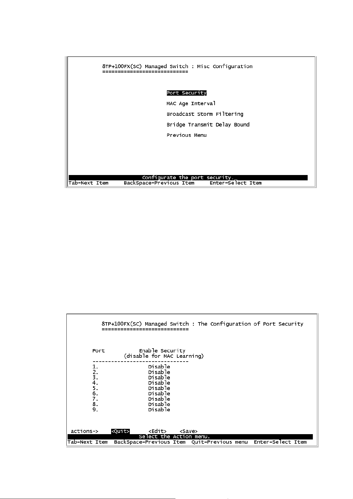
4-3-7.Misc Configuration
4-3-7-1.Port Security
A port in security mode will be “locked” without permission of address
learning. Only the incoming packets with SMAC already existing in the
address table can be forwarded normally. User can disable the port from
learning any new MAC addresses, and then use the static MAC
addresses screen to define a list of MAC addresses that can use the
secure port.
Page 34
1.Press <Edit> to enable or disable the port security.
2.Press Space key to choose enable / disable item.
3.Press ESC to go back action menu line, and then select <Save> to
save all configure value.
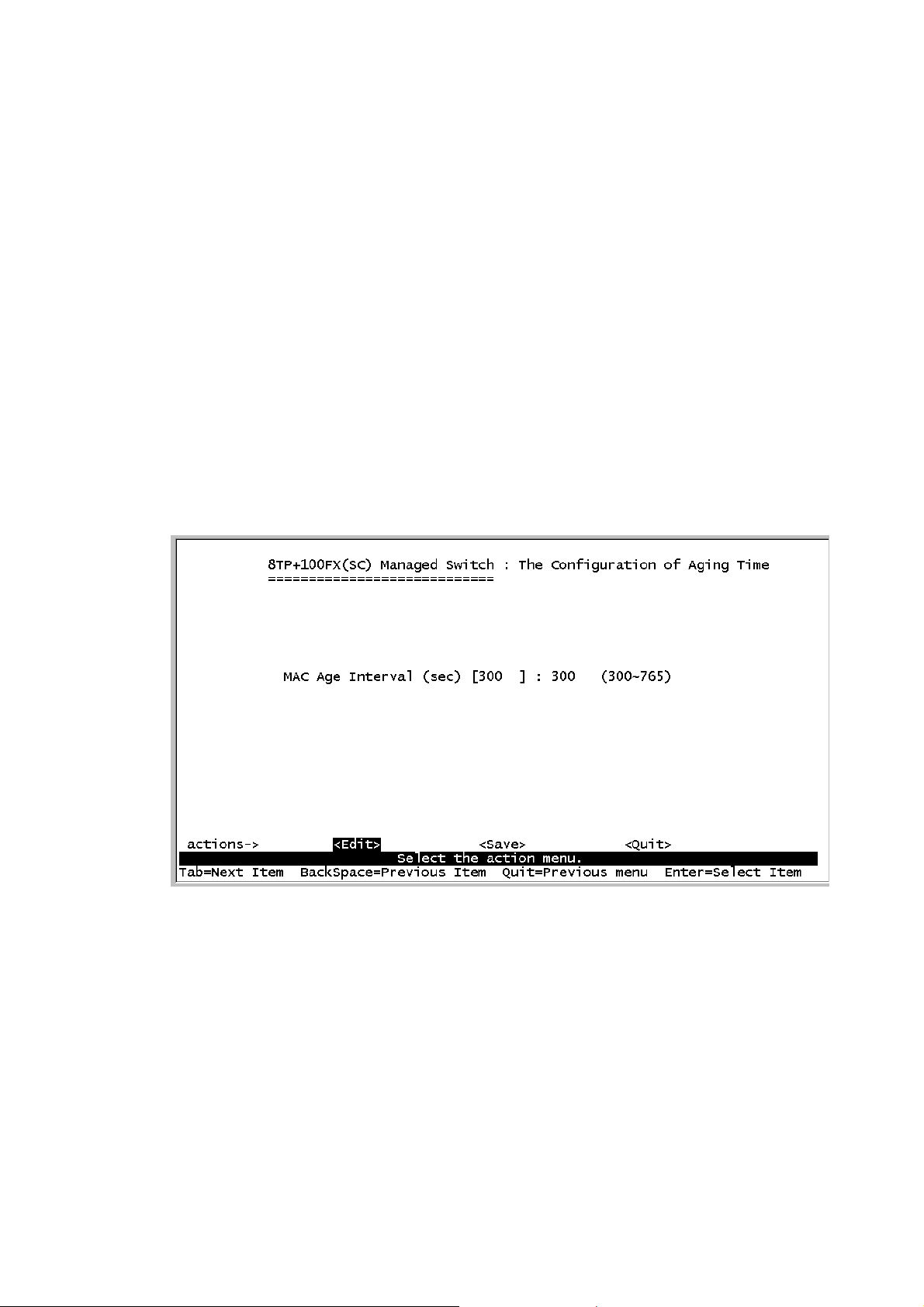
4-3-7-2.MAC Age Interval
Type the number of seconds that an inactive MAC address remains in
the switch’s address table. The valid range is 300~765 seconds. Default
is 300 seconds.
Actions->
<Edit>: Configure all items. Finished configure press ESC to go back
action menu line.
<Save>: Save all configure value.
<Quit>: Exit this page and return to previous menu.
32
Page 35
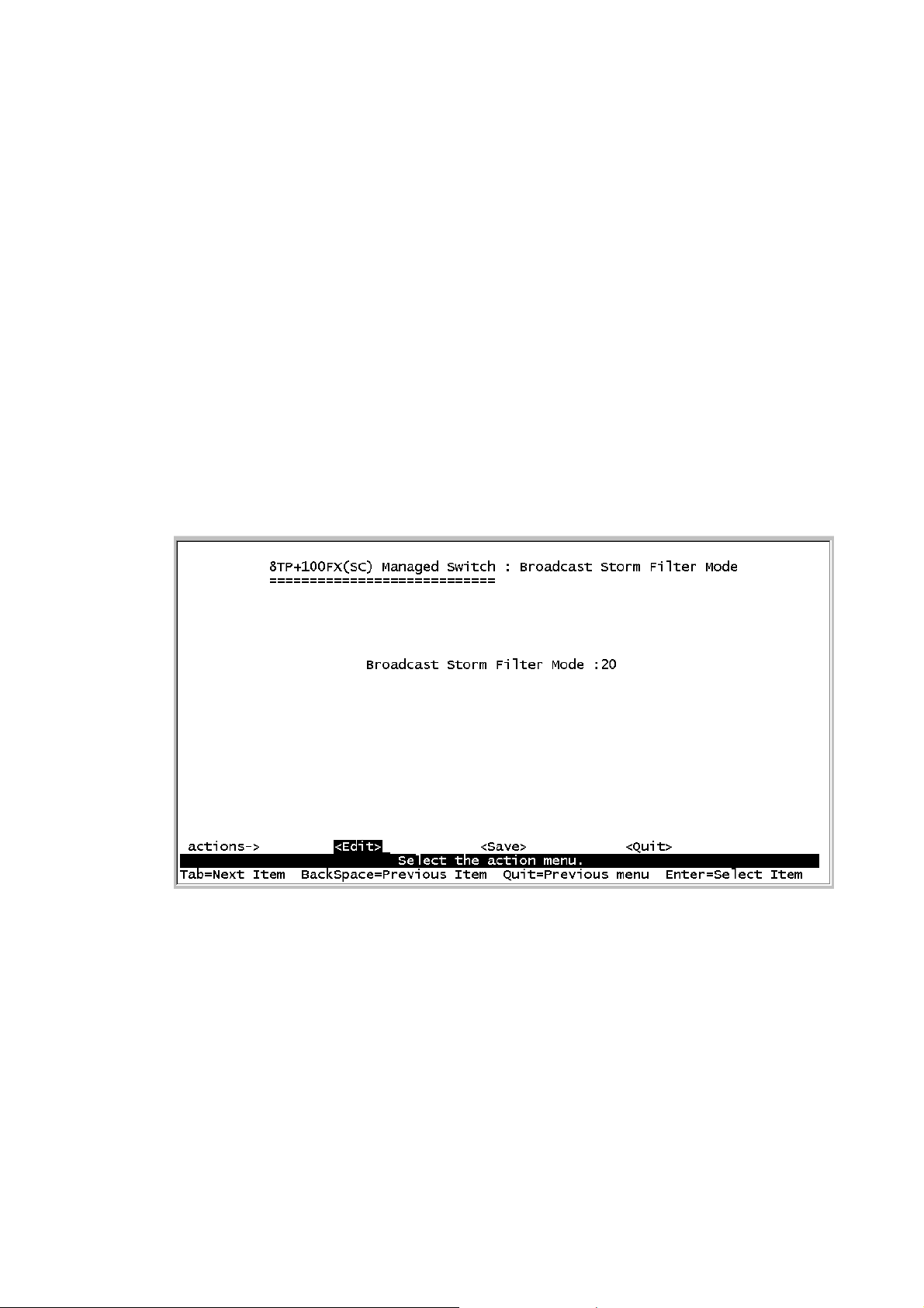
4-3-7-3.Broadcast Storm Filtering
This page is configuring broadcast storm control, press <Edit> to
configure the broadcast storm filter mode.
Press Space key to choose the threshold value. The valid threshold
value are 5%,10%,15%,20%,25% and NO.
Actions->
<Edit>: Configure all items. Finished configure press ESC to go back
action menu line.
<Save>: Save all configure value.
<Quit>: Exit this page and return to previous menu.
Page 36
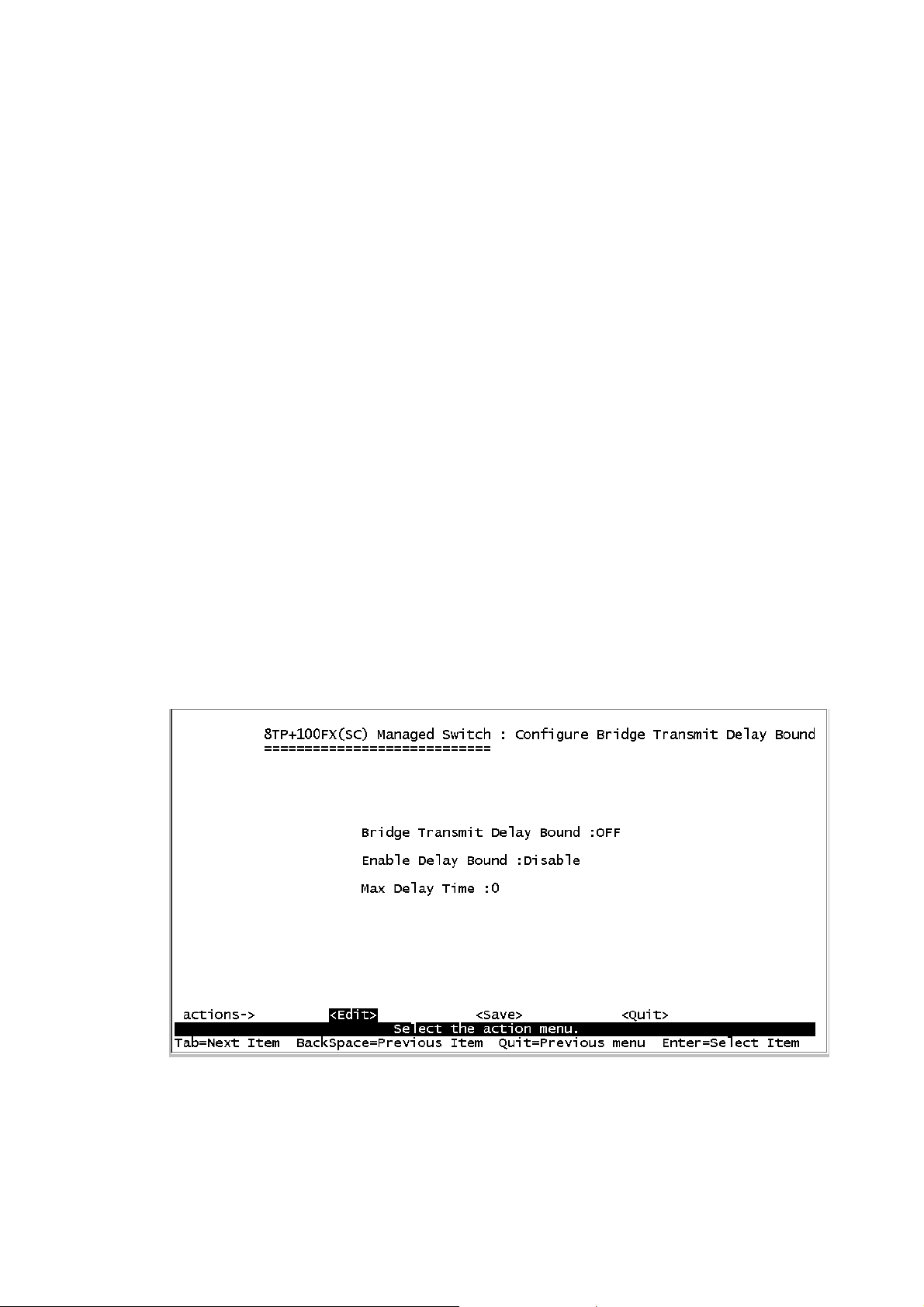
4-3-7-4.Max bridge transmit delay bound
Max bridge transmit delay bound: Limit the packets queuing time in
switch. If enable, the packets queued exceed will be drop. Press Space
key to set the time. This valid value are 1sec, 2sec, 4sec and off. Default
is 1 seconds.
Enable Delay Bound: Limit the low priority packets queuing time in
switch. If enable, the low priority packet stays in switch exceed Max
Delay Time, it will be sent. Press Space key to enable or disable this
function.
Max Delay Time: To set the time that low priority packets queuing in
switch. The valid range is 1~255 ms.
NOTE: Make sure of “Max bridge transit delay bound control” is enabled
before enable Delay Bound, because Enable Delay Bound must be
work under “Max bridge transit delay bound control is enabled” situation.
Actions->
<Edit>: Configure all items. Finished configure press ESC to go back
34
Page 37
action menu line.
<Save>: Save all configure value.
<Quit>: Exit this page and return to previous menu.
4-4.Protocol Related Configuration
4-4-1.STP
4-4-1-1.STP Enable
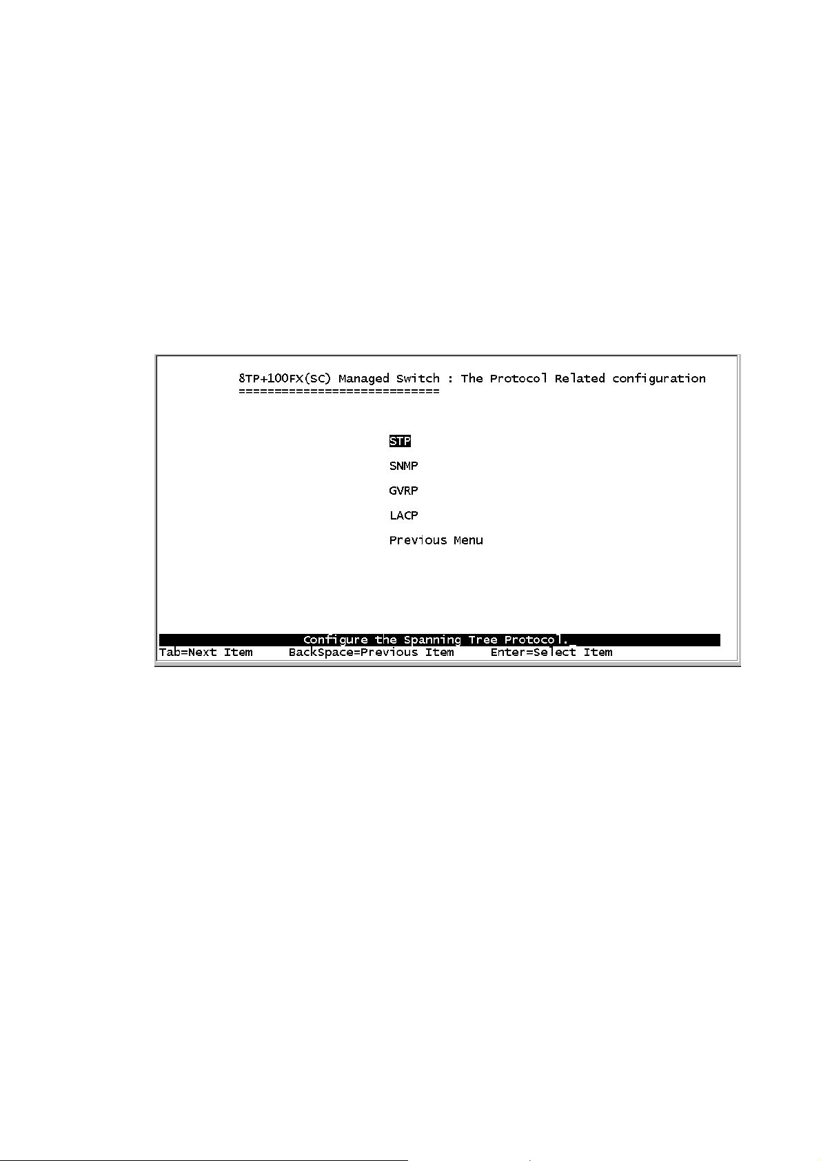
This page is enable or disable Spanning Tree function. Press Space
key to select enable or disable.
Page 38
4-4-1-2.System Configuration
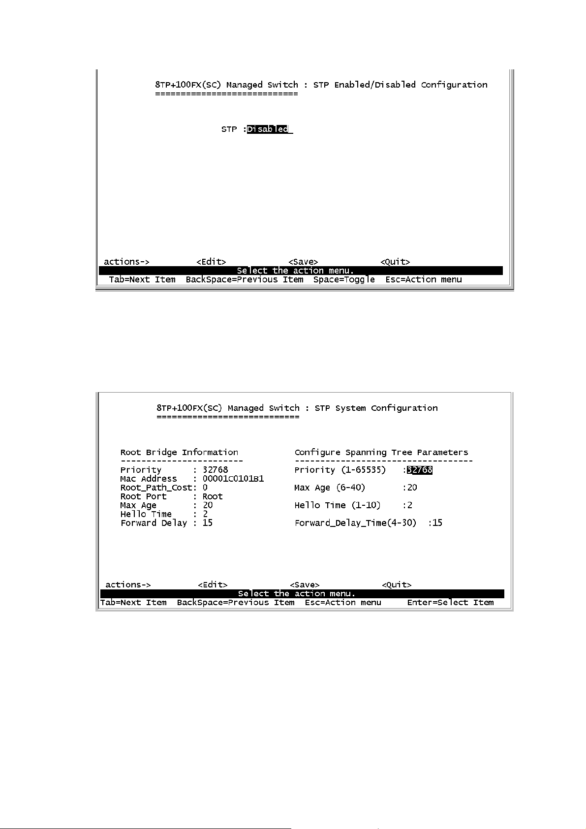
1.You can view spanning tree information about the Root Bridge on the
left.
2.On the right, user can setting new value for STP parameter.
36
Page 39
4-4-1-3.Perport Configuration
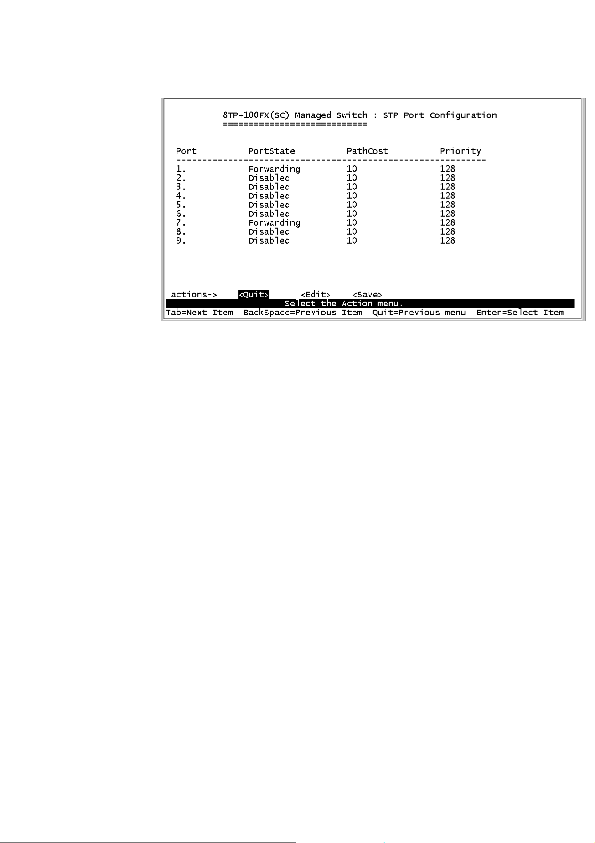
1.PortState: You can view spanning tree status about the switch for per
port.
2.PathCost: Specifies the path cost of the port that switch uses to
determine which port are the forwarding ports. If you change the value,
you need to restart the switch for valid value.
3.Priority: This is mean port priority; you can make it more or less likely
to become the root port. If you change the value, you need to restart the
switch for valid value.
Page 40
4-4-2.SNMP
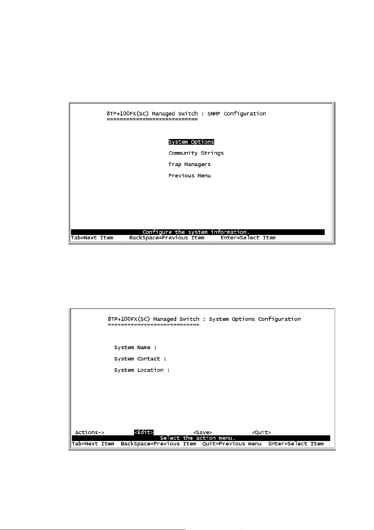
Use this page to define management stations as trap managers and to
enter SNMP community strings. User can also define a name, location,
and contact person for the switch.
4-4-2-1.System Options
Press <Edit> to enter all items, and then press <Save> to save
configure value.
38
Page 41
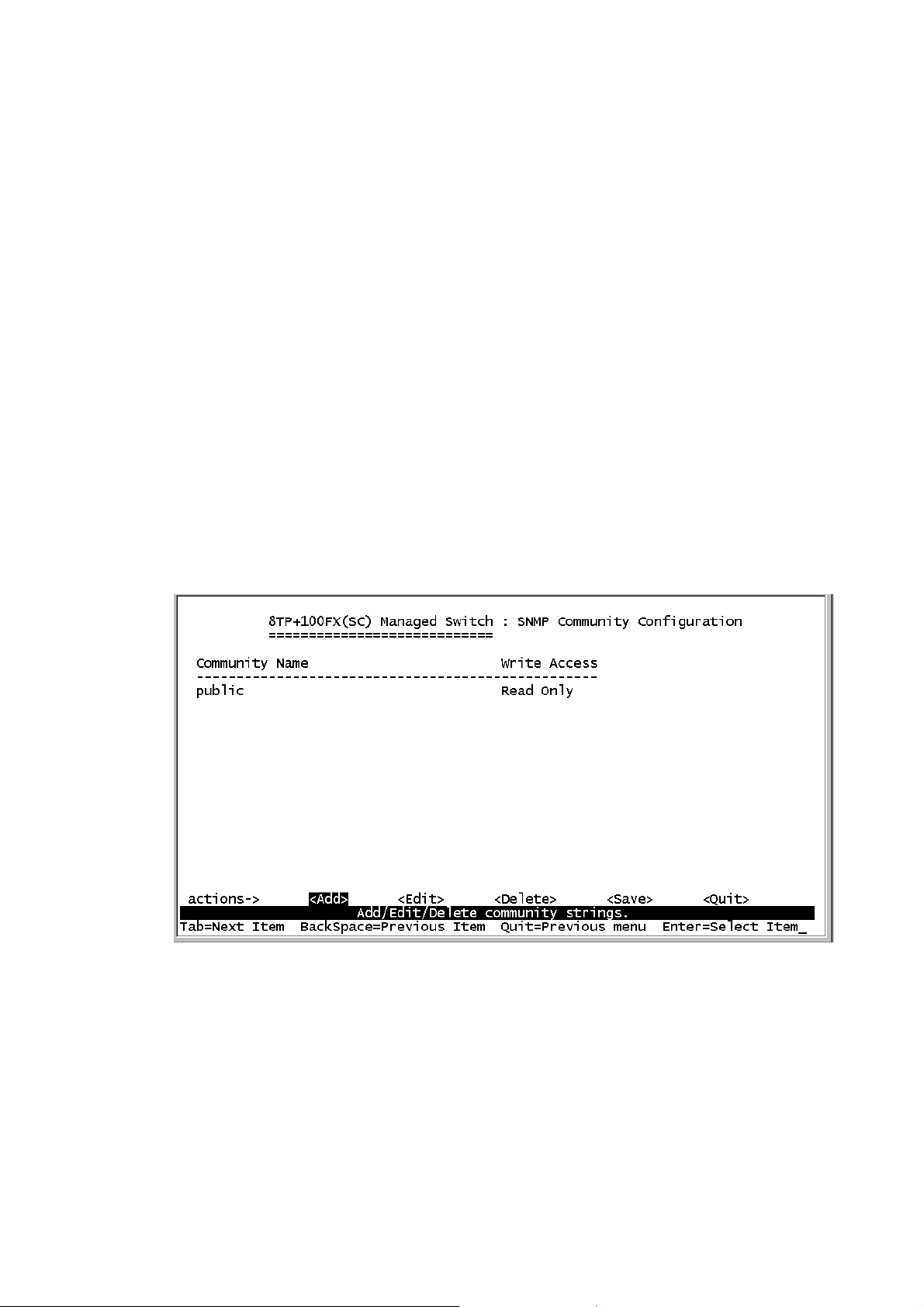
1.System Name: Type a name to be used for the switch.
2.System Contact: Type the name of contact person or organization.
3.System Location: Type the location of the switch.
4-4-2-2.Community Strings
Use this page to enter SNMP community strings.
1.Community Name: Type the name of current strings.
2.Write Access: Enable the rights is read only or read/write.
Read only: Read only, enables requests accompanied by this string to
display MIB-object information.
Read/Write: Read write, enables requests accompanied by this string to
display MIB-object information and to set MIB objects.
Page 42
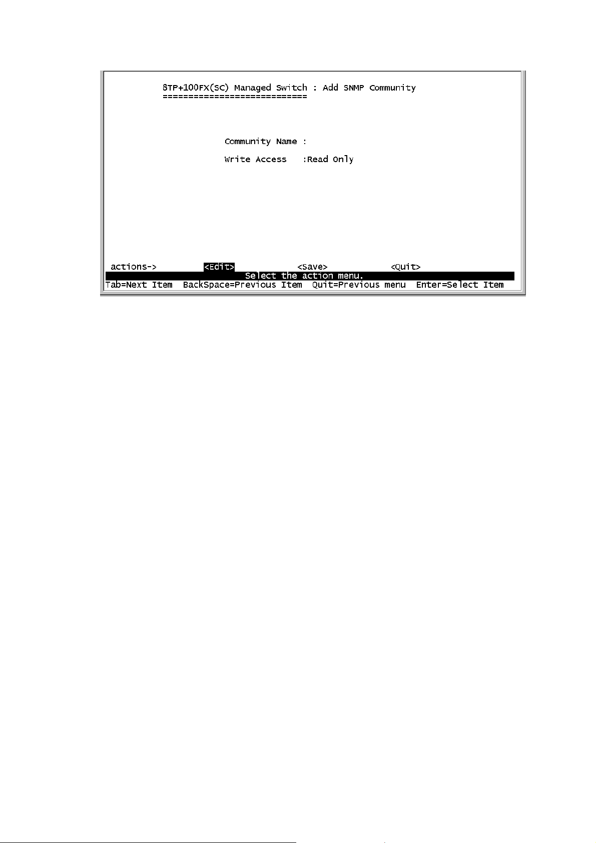
Actions->
<Add>: Create a community strings.
<Edit>: Modify all items. Finished configure press ESC to go back
action menu line.
<Delete>: Delete a community strings. After delete item press <Save>
to complete the deleting operation.
<Save>: Save all configure value.
<Quit>: Exit this page and return to previous menu.
4-4-2-3.Trap Managers
A trap manager is a management station that receives traps, the system
alerts generated by the switch. If no trap manager is defined, no traps
are issued. Create a trap manager by entering the IP address of the
station and a community string.
40
Page 43
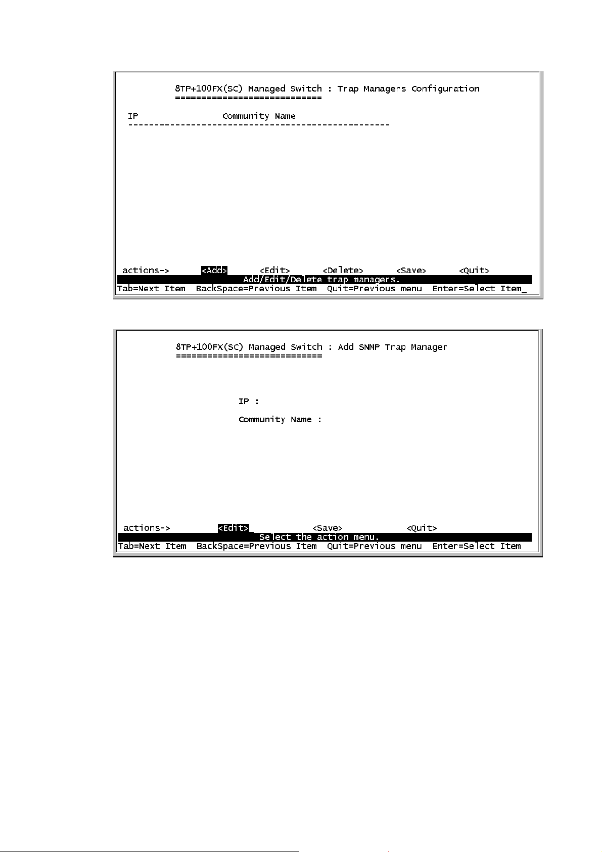
Actions->
<Add>: Create a trap manager.
<Edit>: Modify all items. Finished configure press ESC to go back
action menu line.
<Delete>: Delete a trap manager. After delete item press <Save> to
Page 44
complete the deleting operation.
<Save>: Save all configure value.
<Quit>: Exit this page and return to previous menu.
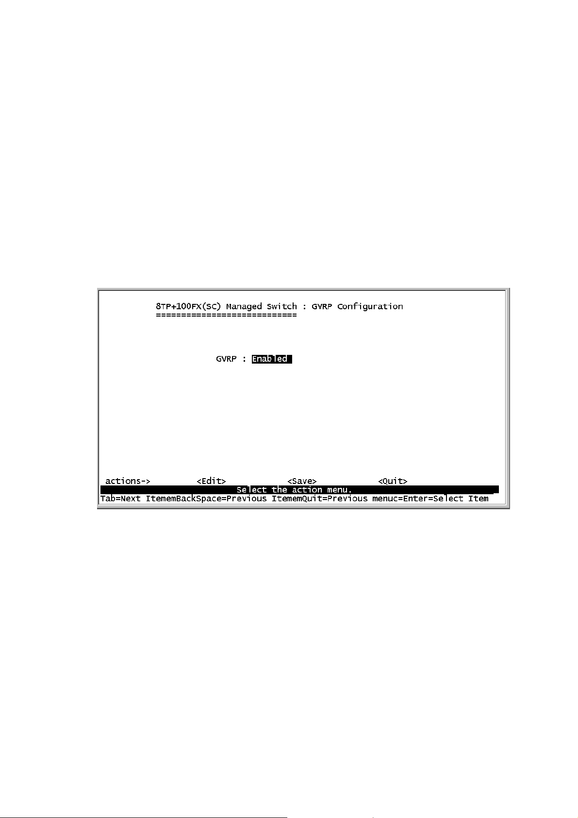
4-4-3.GVRP
This page you can enable / disable the GVRP (GARP VLAN
Registration Protocol) support.
Press Space key to choose Enabled / Disabled.
Actions->
<Edit>: Configure all items. Press Space key to choose Enable or
Disabled mode. Finished configure press ESC to go back action menu
line.
<Save>: Save all configure value.
<Quit>: Exit this page and return to previous menu.
42
Page 45
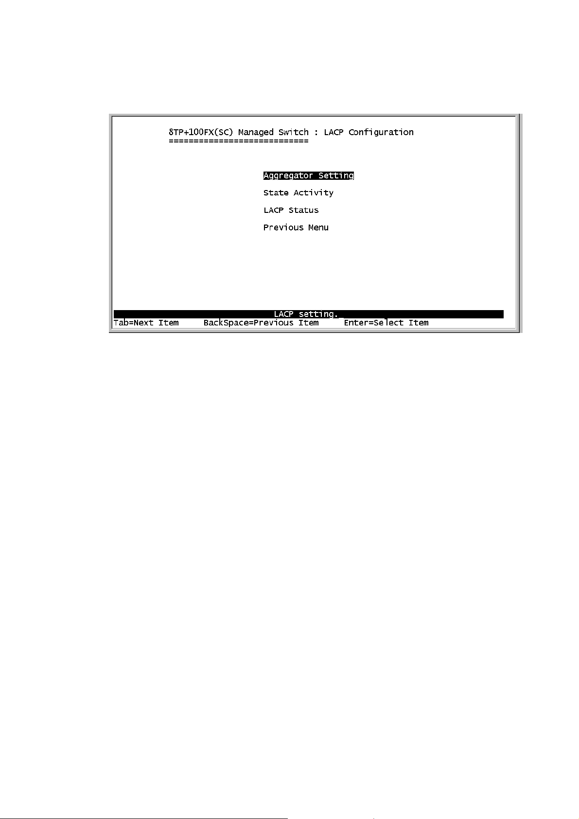
4-4-4.LACP
4-4-4-1.Aggregator Setting
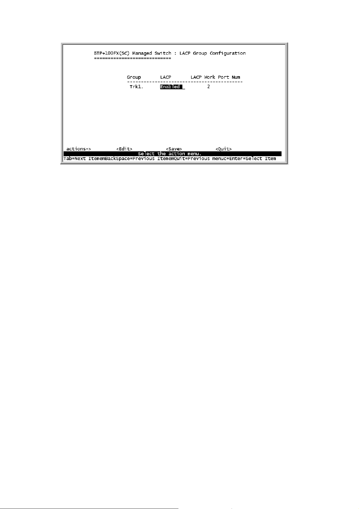
1.Group: Display the trunk group ID.
2.LACP: Press Space key to enable or disable LACP (Link Aggregation
Control Protocol) support. If enable, the group is LACP static trunking
group. If disable, the group is local static trunking group.
3.LACP Work Port Num: The max number of ports can be aggregated
at the same time. If LACP static trunking group, the exceed ports is
standby and able to aggregate if work ports fail. If local static trunking
group, the number must be the same as group ports.
NOTE: Before set LACP support, you have to set trunk group on the
page of Port / Trunk Configuration first.
Page 46
Actions->
<Edit>: Configure all items. Finished configure press ESC to go back
action menu line.
<Save>: Save all configure value.
<Quit>: Exit this page and return to previous menu.
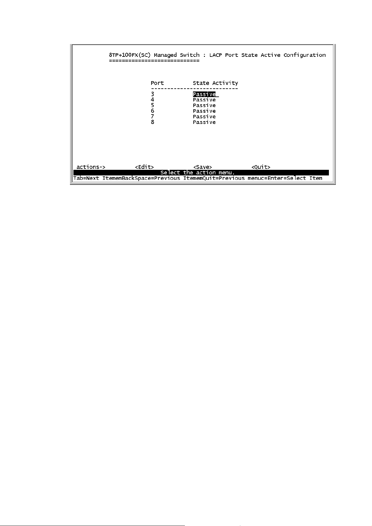
4-4-4-2.State Activity
Active: The port automatically sends LACP protocol packets.
Passive: The port does not automatically sends LACP protocol packets,
and responds only if it receives LACP protocol packets from the
opposite device.
44
Page 47
Actions->
<Edit>: Configure all items. Finished configure press ESC to go back
action menu line.
<Save>: Save all configure value.
<Quit>: Exit this page and return to previous menu.
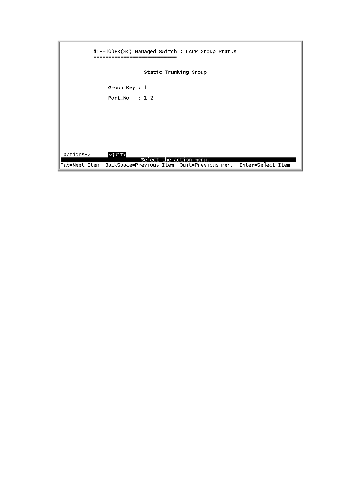
4-4-4-3.LACP Status
When you setting trunking group, you can see relation information in
here.
Page 48
Actions->
<Quit>: Exit this page and return to previous menu.
<Previous Page>: Return to previous page to view.
<Next page>: Go to next page to view.
4-5.Reboot Switch
Default: Reset switch to default configuration.
Restart: Reboot the switch in software reset.
46
Page 49
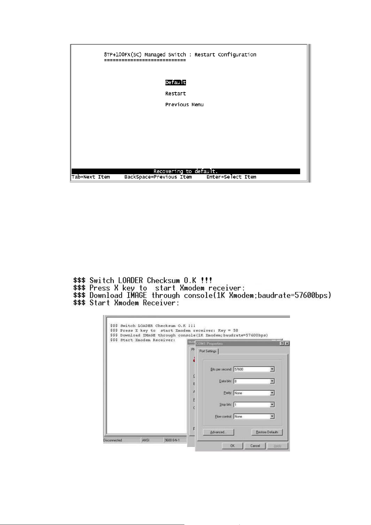
4-6. X-modem Upgrade
1.Press X key to start upgrading for X-modem.
1. First, disconnect terminal and modify baud rate to 57600bps, then do
the connection again.
3.Select “send file" under "transfer" menu from menu bar.
4.Press "browse" button to select the path.
Page 50
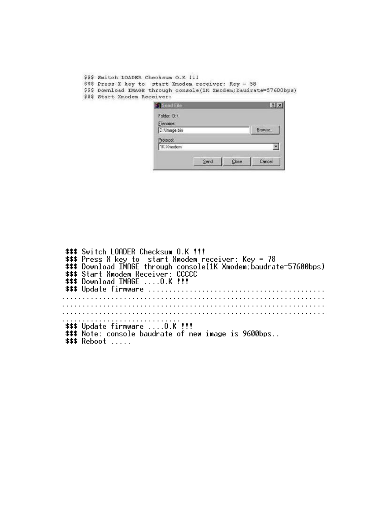
5.Select "1K X-modem" of protocol and press "Send" button.
6.After successfully upgraded the new firmware, please modify baud
rate to 9600bps.
48
Page 51

5.
Web-Based Management
This section introduces the configuration and functions of the
Web-based management of 8TP+ 1Fiber Management Switch series.
The 8TP+ 1Fiber Management Switch series provides an embedded
HTML website residing in flash memory. It offers management feature
and allows users to manage the 8TP+1Fiber Management Switch from
anywhere on the network through a standard Web Browser.
NOTE: For those who use Win2000 have the Service Pack2
function, the web management function will have unexpected
display if the IE version is below version 5.5.
Web Management Function
1. Web Management Function provides a Web browser to manage and
monitor the switch, the default values as follows:
If you need change IP address in first time, you can use console mode
to modify it.
IP Address: 192.168.16.1
Subnet Mask: 255.255.255.0
Default Gateway:192.168.16.254
User Name: root
Password: root
2. You can browse http://192.168.16.1, type user name and password
Page 52
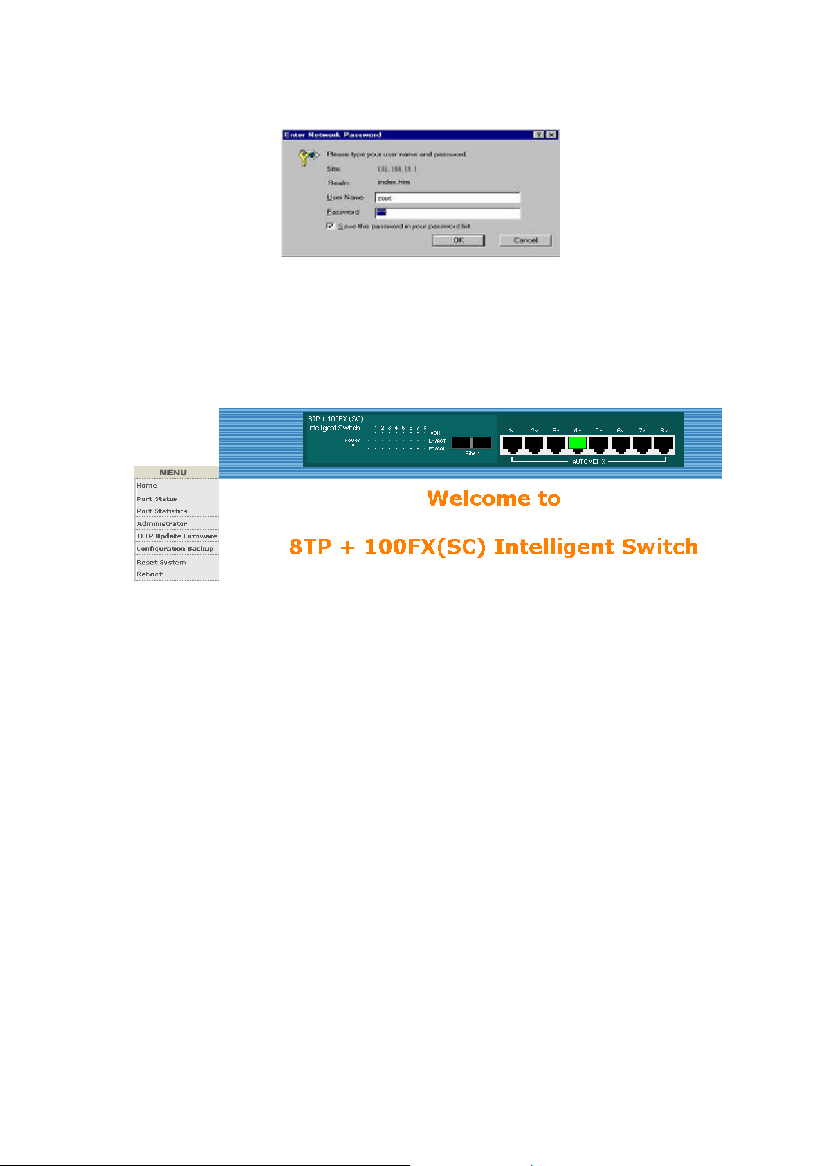
as above.
5-1. Web Management Home Overview (The image was
captured from 8TP + 100FX)
1. Home Page.
5-2. Port status
1. port status
State: Display port status off or on depended on user setting. “unlink”
will be treated as “off ”.
Link Status: Down is “No Link”, UP is “Link”
Auto Negotiation: auto negotiation mode
Speed status: Display 100Mbps or 10Mbps speed, Port 1- 8 is
10/100Mbps, Port 9 is 100 Mbps.
Duplex status: Display full-duplex or half-duplex mode.
Flow control: Display flow control status enable or disable mode
Config: Display the state of user setting.
Atual: Display the negotiation result.
50
Page 53
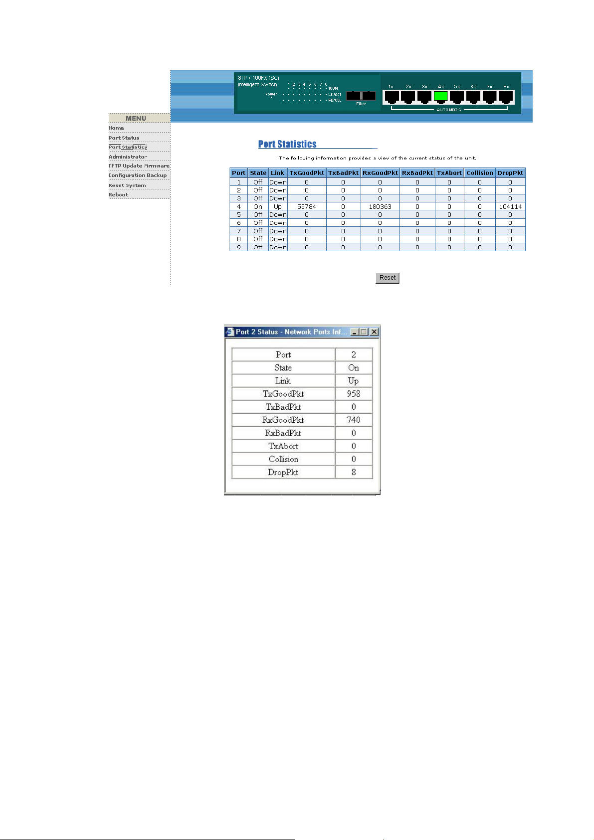
User can see a single port counter as follows
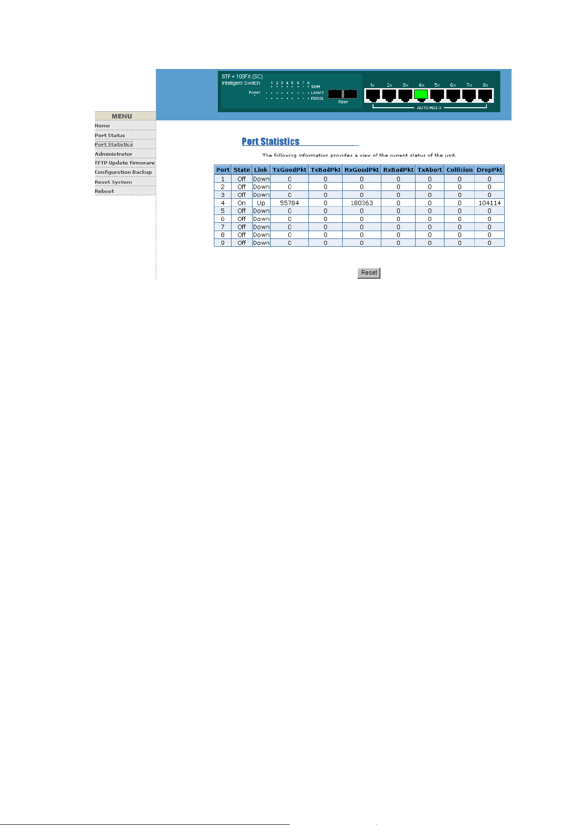
5-3. Port Statistics
1. The following information provides a view of the current status of the
unit.
Page 54
5-4. Administrator
Those management functions include:
IP address, Switch settings, Console port information, Port controls
Link aggregation, Filter database, VLAN configuration ,Spanning
Tree, Port Mirror, SNMP, Security Manager, TFTP Update Firmware
Configuration Backup, Reset system and Reboot.
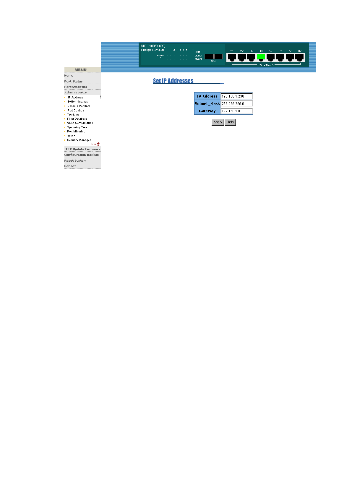
5-4-1. IP Address
1. User can configure the IP Settings and fill in the new value, than
clicks apply button.
2. User must be reset switch and use new IP address to browser this
web management.
52
Page 55
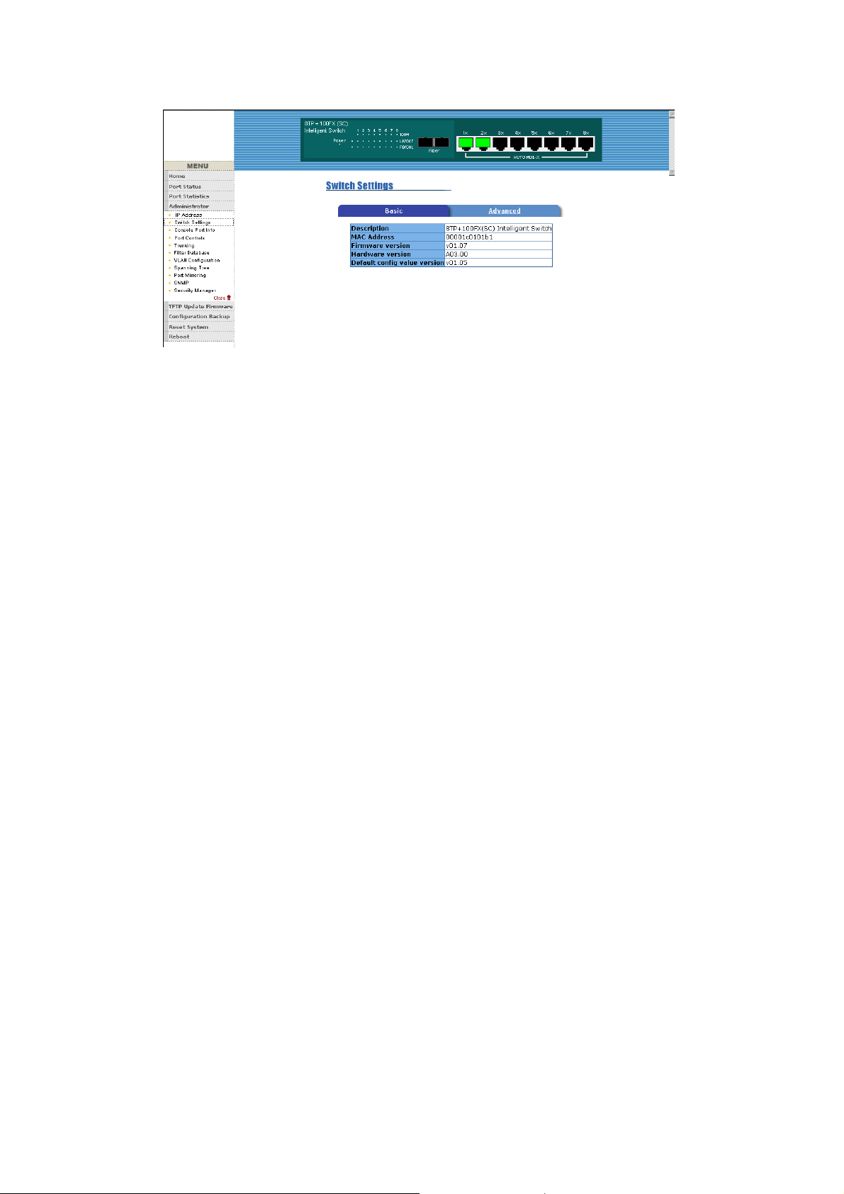
5-4-2. Switch Setting
5-4-2-1.Basic
1. Description: Display the name of device type.
2. MAC Address: The unique hardware address assigned by
manufacturer (default)
3. Firmware Version: Display the switch’s firmware version.
4. Hardware Version: Display the switch’s Hardware version.
5. Default configure value version: Display write to default
EEPROM value version.
Page 56
5-4-2-2.Advanced
Miscellaneous Setting :
MAC Address Age-out Time: Type the number of seconds that an
inactive MAC address remains in the switch's address table. The valid
range is 300~765 seconds. Default is 300 seconds.
Max bridge transit delay bound control: Limit the packets queuing
time in switch. If enable, the packets queued exceed will be drop. This
valid value are 1sec, 2 sec, 4 sec and off. Default is 1 seconds.
Broadcast Storm Filter: To configure broadcast storm control, enable it
and set the upper threshold for individual
ports. The threshold is the percentage of the port's total bandwidth used
by broadcast traffic. When broadcast traffic for a port rises above the
threshold you set, broadcast storm control becomes active. The valid
threshold value are 5%, 10%, 15%, 20%, 25% and off.
54
Page 57
.
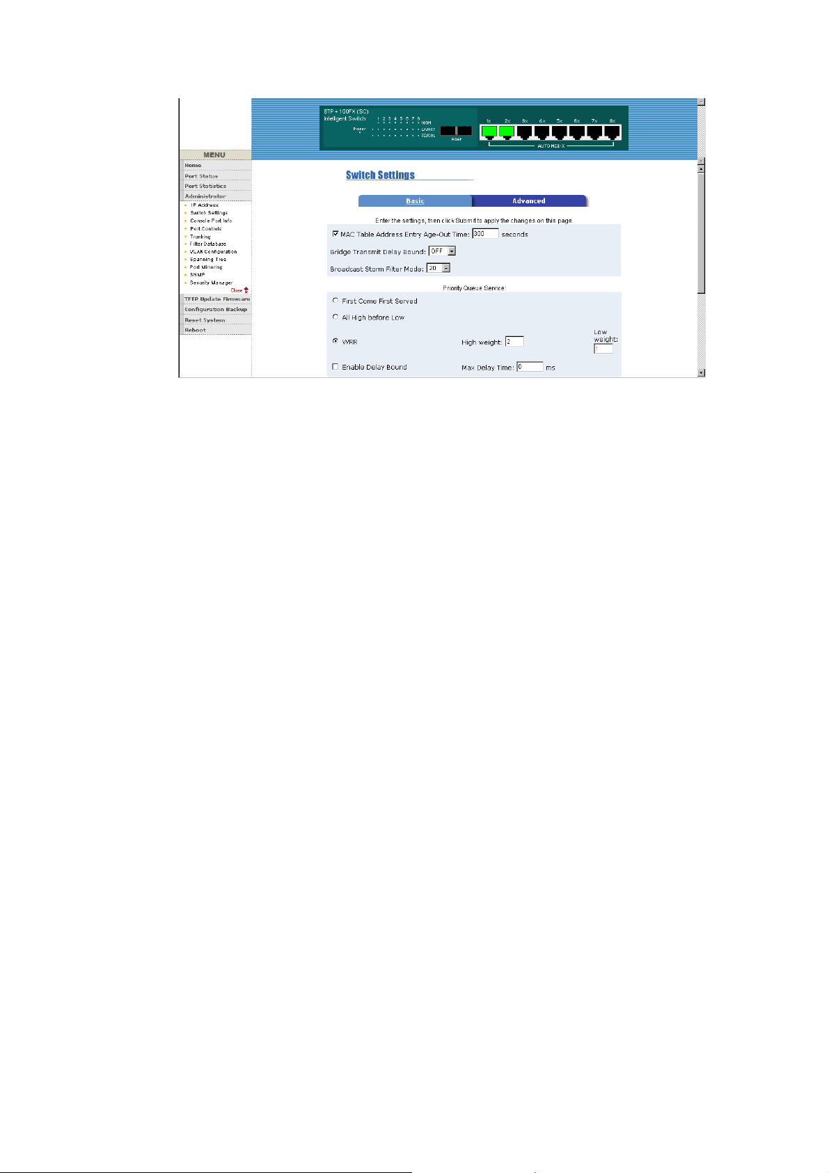
Priority Queue Service settings:
First Come First Service: The sequence of packets sent is depend on
arrive order.
All High before Low: The high priority packets sent before low priority
packets.
Weighted Round Robin: Select the preference given to packets in the
switch's high-priority queue.
These options represent the number of high priority packets sent before
one low priority packet is sent. For example, 2 High :1 Low means that
the switch sends 2 high priority packets before sending 1 low priority
packet.
Enable Delay Bound: Limit the low priority packets queuing time in
switch. Default Max Delay Time is 255ms.
If the low priority packet stays in switch exceed Max Delay Time, it will
be sent. The valid range is 1~255 ms.
NOTE: Make sure of “Max bridge transit delay bound control” is enabled
before enable Delay Bound, because Enable Delay Bound must be
work under “Max bridge transit delay bound control is enabled” situation.
Page 58
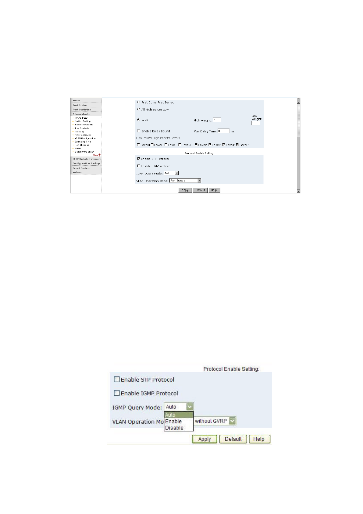
Qos Policy: High Priority Levels: 0~7 priority level can map to high or
low queue. When the VLAN Tag number of a frame is mapping the
priority level of the port, and this frame can have high priority.(This QoS
Policy is for global Switch, not for any single port)
Protocol Enable Setting :
Enable Spanning Tree Protocol : Default recommend to enable STP
Enable Internet Group Multicast Protocol: enable IGMP protocol
IGMP Query Mode: Recognize different Query from client or server to
decide which Queryer will be the first priority, they are three mode as
follow:
1. Auto Mode: Choose the indicated Switch, which has the smallest IP
address will be set for the IGMP Queryer.
2. Enable Mode: Enable one of Switch to be the IGMP Queryer.
3. Disable Mode: Disable the other Switches to be the IGMP Queryer.
VLAN Operation Mode:
56
Page 59
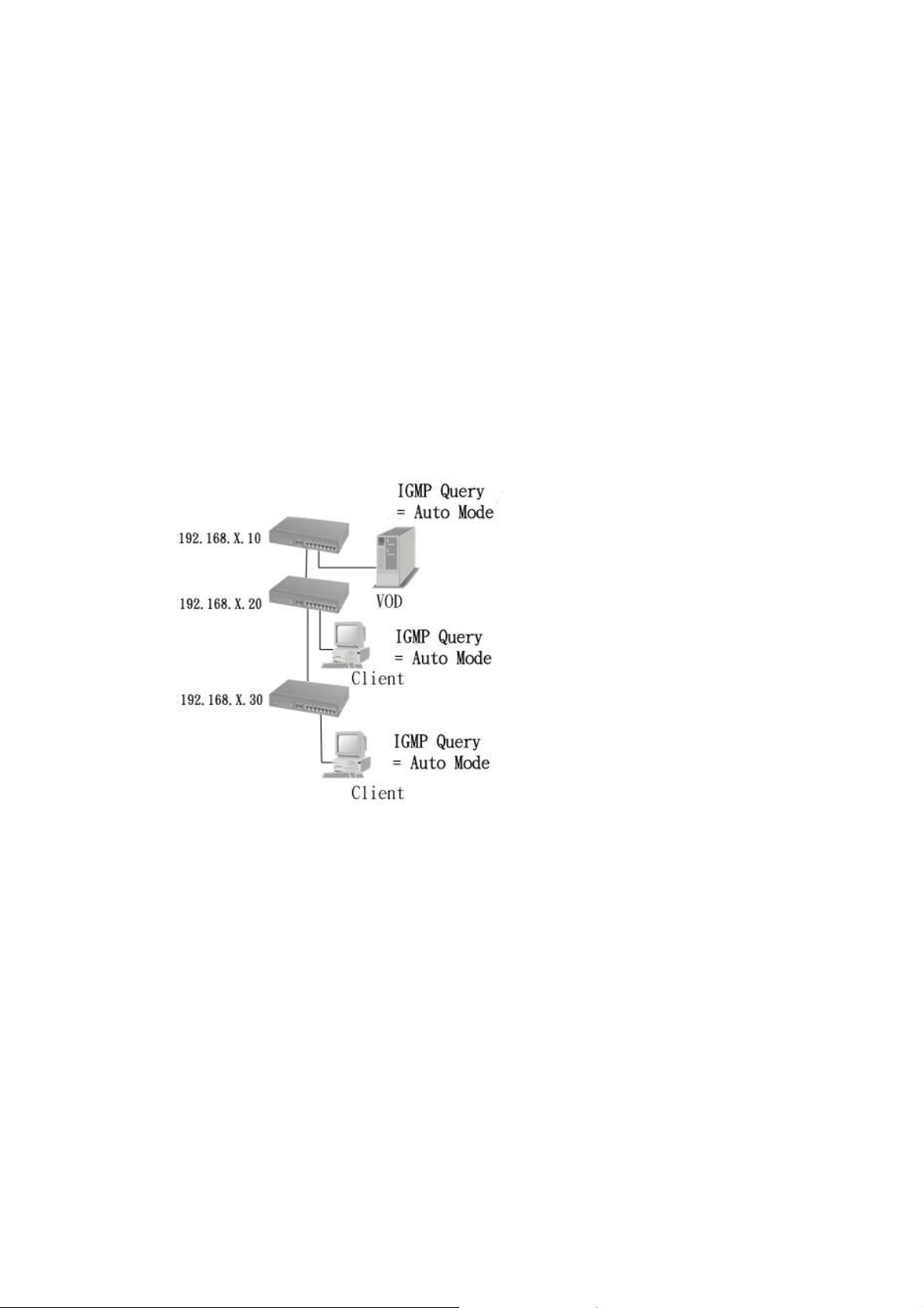
No VLAN
802.1Q(Tag VLAN) without GVRP VLAN mode
802.1Q(Tag VLAN) with GVRP VLAN mode (Default)
Port Based
Also, three kind of typologies shown as below indicate how the IGMP
Query work within a network:
1. This topology has to be set for when the router’s IP address is
smaller than other Switch in subnet.
2. This topology has to be set for when the router’s IP address is not
smaller than other Switch in subnet.
Page 60
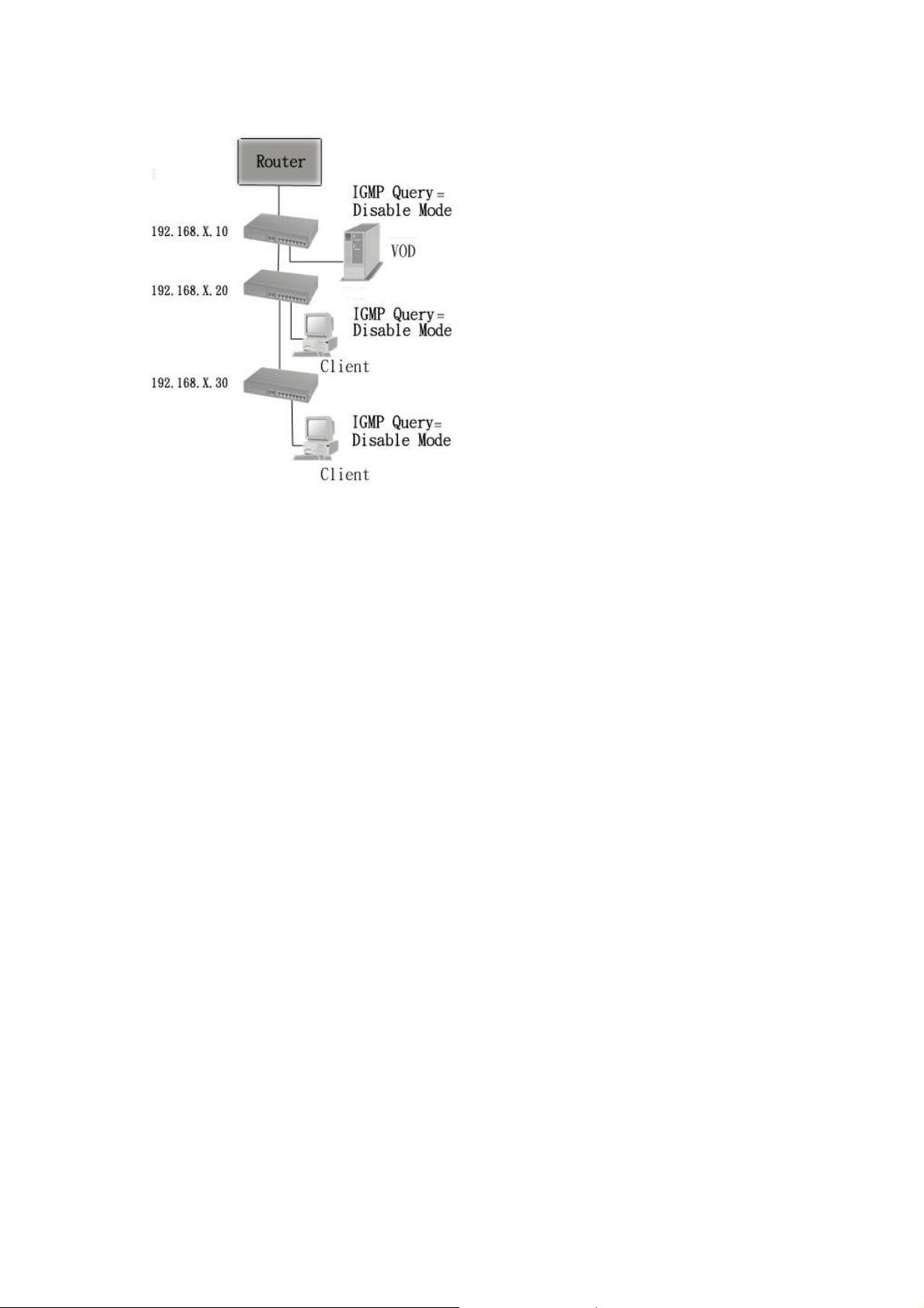
Note: This Router supports IGMP protocol, but IGMP function has to be
in enable mode, and the Router has to be the Queryer.
3. This topology must be set for when the Switch’s IP address is not the
smallest in the subnet. If in Auto mode, the network will cause multi-cast
storm from the client IGMP report, the topology shown as below is
necessary to be set for.
58
Page 61
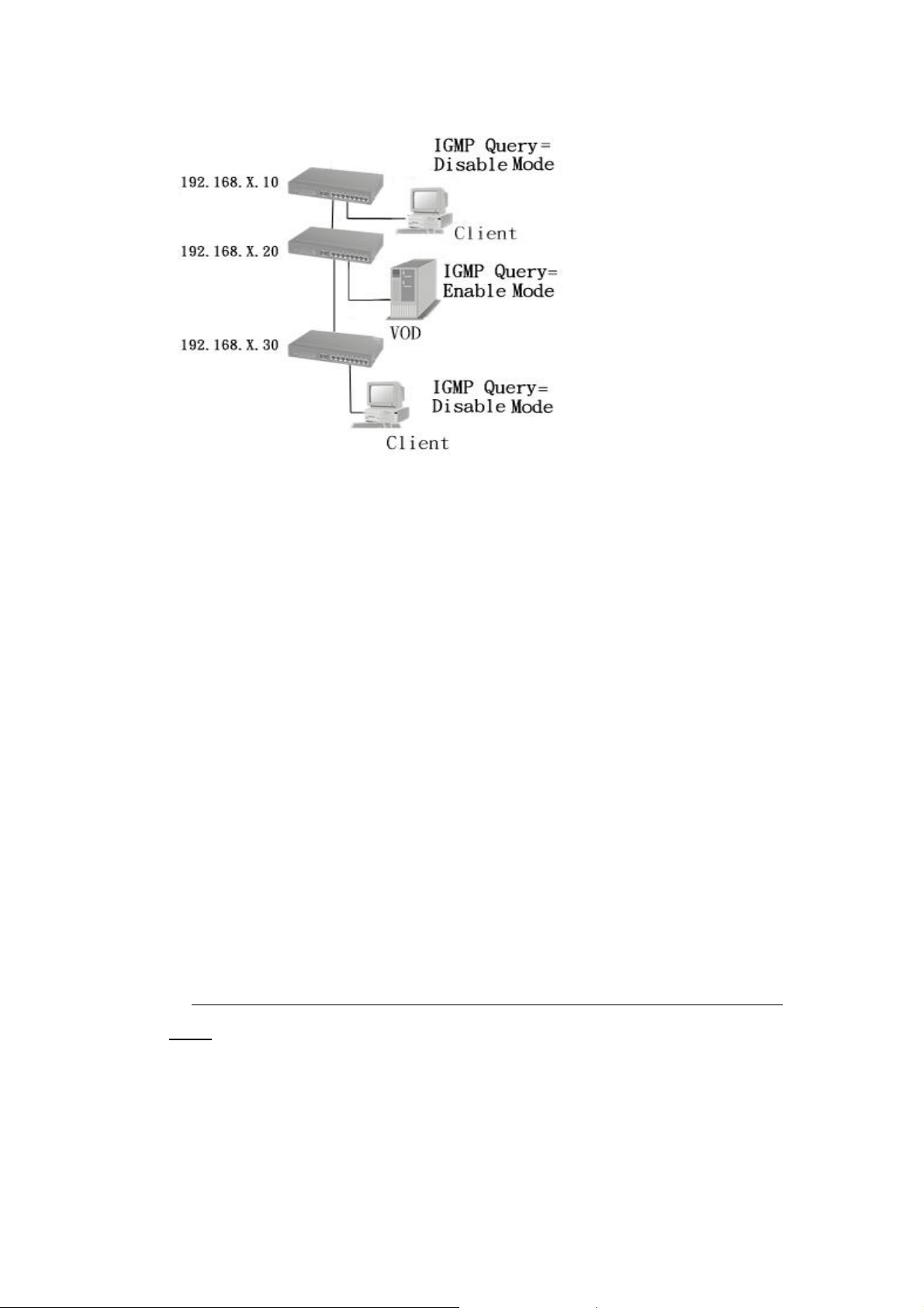
Note: Suggest VOD server set with Switch has smallest IP address.
4. All of Switch must be in Disable mode, When VOD server is set up for
IGMP Queryer.
GVRP (GARP [Generic Attribute Registration Protocol] VLAN
Registration Protocol)
GVRP allows automatic VLAN configuration between the switch and
nodes. If the switch is connected to a device with GVRP enabled, you
can send a GVRP request using the VID of a VLAN defined on the
switch, the switch will automatically add that device to the existing
VLAN.
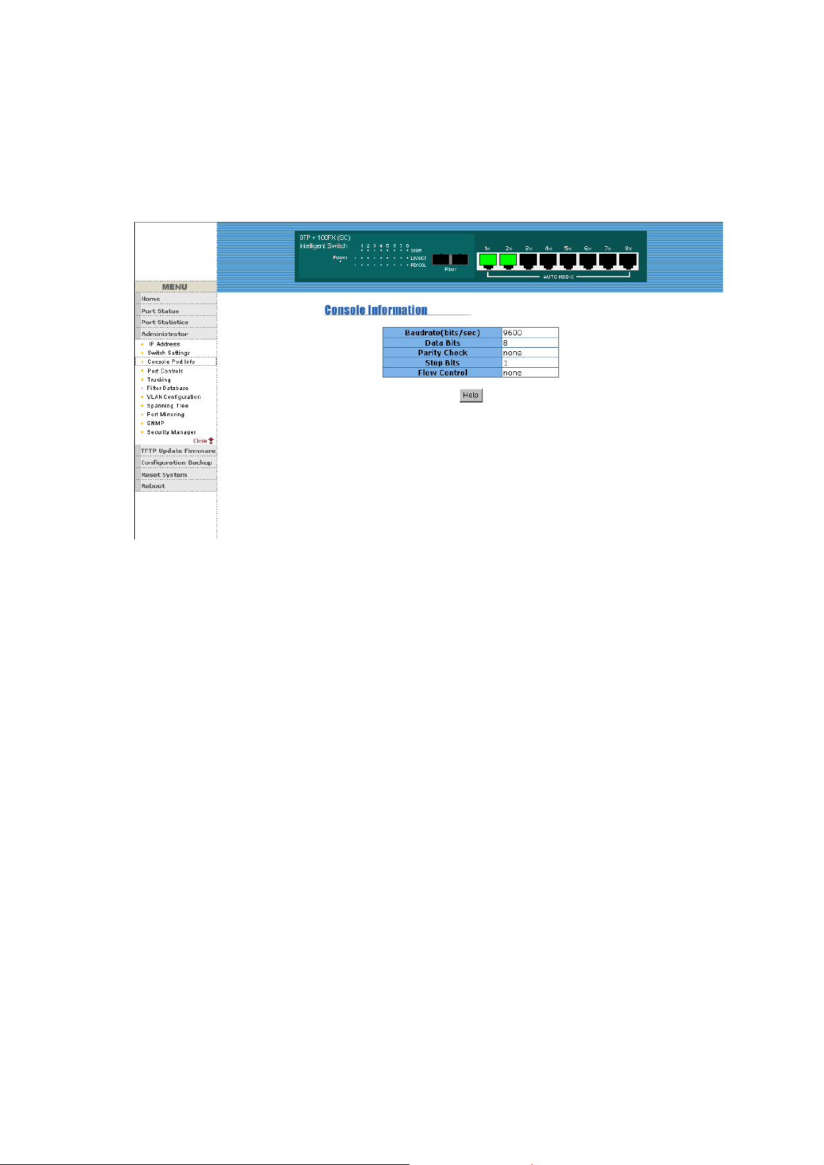
5-4-3. Console Port Information
1. Console is a standard UART interface to communicate with Serial
Port.
User can use windows HyperTerminal program to link the switch.
Connect To->Configure
Baud rate (bits/sec):
9600
Data bits: 8
Parity check: none
Page 62
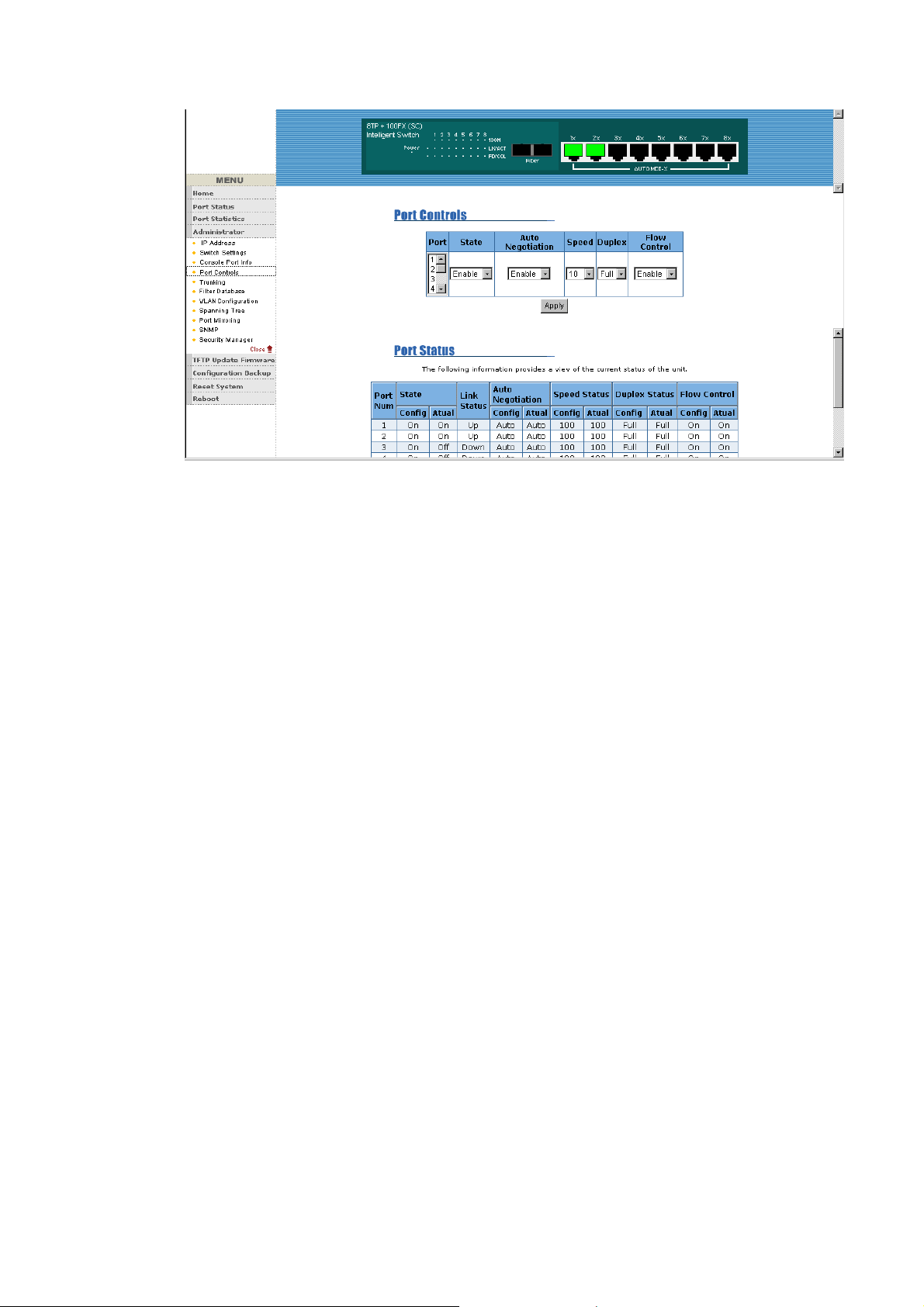
5-4-4. Port Controls
1. This page can Change every port status
State: User can disable or enable this port control
Auto Negotiation: User can set auto negotiation is enable or disable of
per port
Speed setting: User can set 100Mbps or 10Mbps speed (Port1~Port8)
Duplex setting: User can set full-duplex or half-duplex mode
Flows control setting: User can set flow control function is enable or
disable
60
Page 63
5-4-5. Trunking
The Trunking provides a standardized means for exchanging
information
between Partner Systems on a link to allow their Link Aggregation
Control instances to reach agreement on the identity of the Link
Aggregation Group to which the link belongs, move the link to that Link
Aggregation
Group, and enable its transmission and reception functions in an orderly
manner. In conclusion, Link aggregation lets you group up to eight
consecutive ports into a single dedicated connection. This feature can
expand bandwidth to a device on the network. LACP operation
requires full-duplex mode, more detail information refer to IEEE
802.3ad.
5-4-5-1. Aggregator setting
System Priority : A value used to identify the active LACP. The switch
Page 64
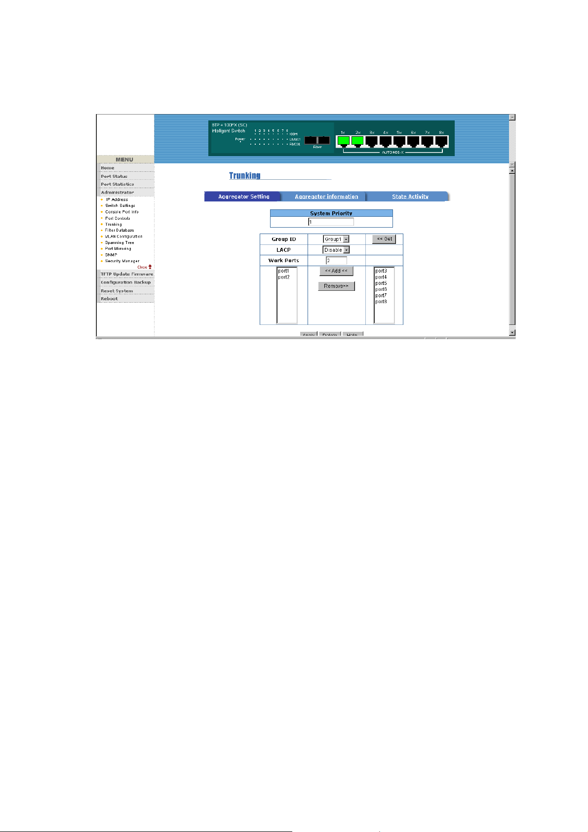
with the lowest value has the highest priority and is selected as the
active LACP.
1.Group ID: you can create a link aggregation across two or more ports,
choose the "group id" and click "Get".
2.LACP: If enable, the group is LACP static trunking group. If disable,
the group is local static trunking group.
All ports support LACP dynamic trunking group. If connecting to the
device that also supports LACP, the LACP dynamic trunking group will
be created automatically.
3. Work ports:The max number of ports can be aggregated at the same
time. If LACP static trunking group, the exceed ports is standby and able
to aggreate if work ports fail. If local static trunking group, the number
must be the same as group ports.
4. Select the ports to join the trunking group
5. If LACP enable, you can configure LACP Active/Passive status in
each ports.
6. Click Apply.
62
Page 65
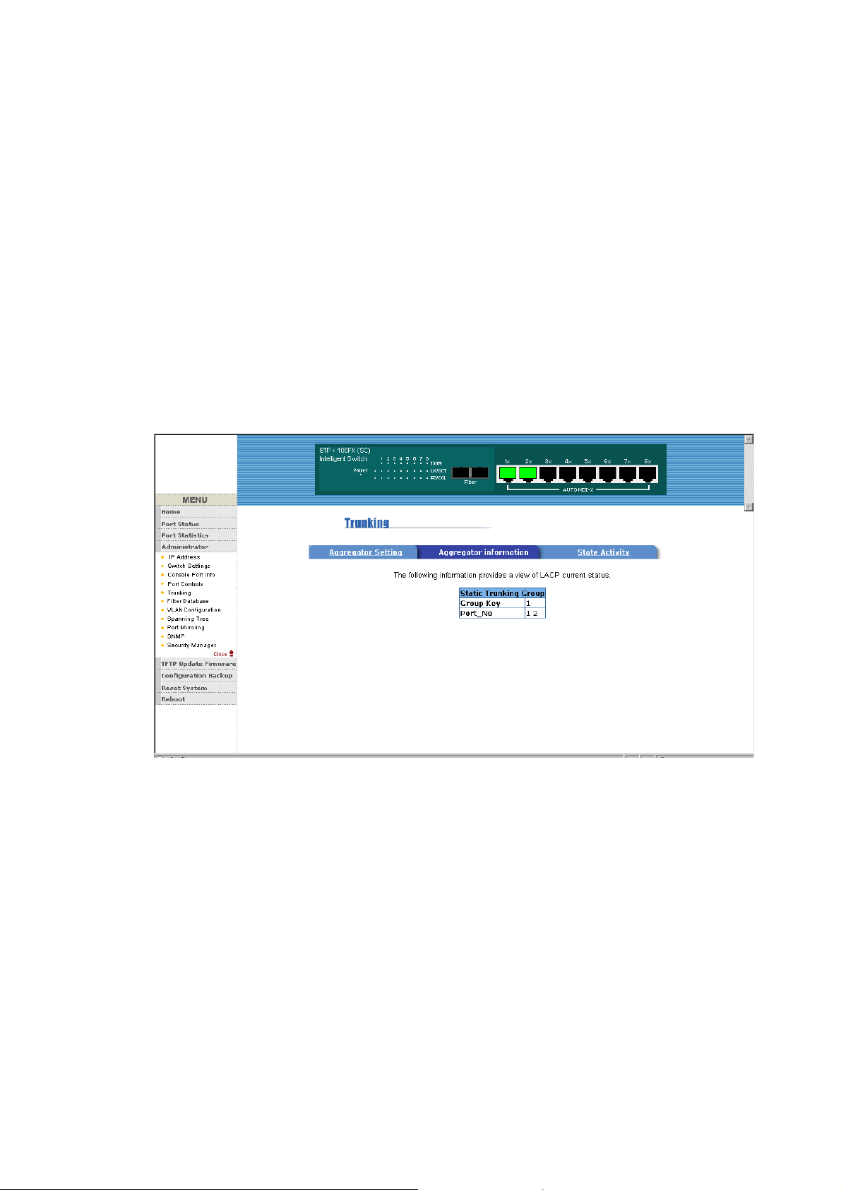
5-4-5-2. Aggregator Information
When you are setting LACP aggregator, you can see relation
information in here.
5-4-5-3. State Activity
Active (select): The port automatically sends LACP protocol packets.
Passive (no select): The port does not automatically sends LACP
protocol packets, and responds only if it receives LACP protocol packets
from the opposite device.
1. A link having either two active LACP ports or one active port can
Page 66
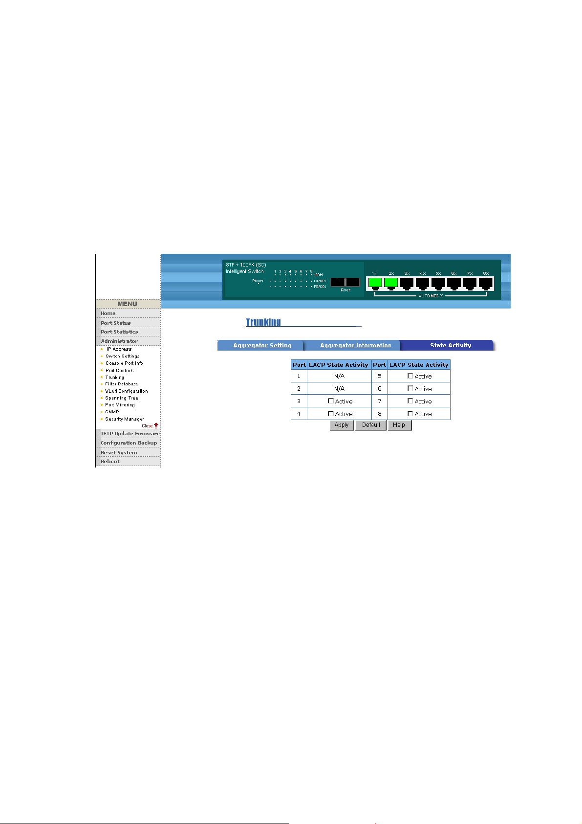
perform dynamic LACP trunking.
A link has two passive LACP ports will not perform dynamic LACP
trunking because both ports are waiting for and LACP protocol packet
from the opposite device.
2. If you are active LACP’s actor, when you are select trunking port, the
active status will be created automatically.
64
Page 67
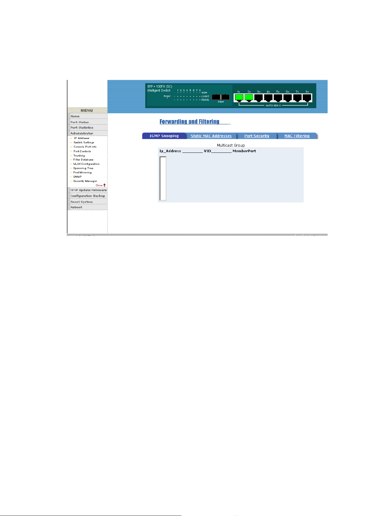
5-4-6. Filter Database
5-4-6-1. IGMP Snooping
The 8TP+1Fiber Management Switch support IP multicast , you can
enable IGMP protocol on web management’s switch setting advanced
page, then display the IGMP snooping information in this page, you can
view difference multicast group ,VID and member port in here, IP
multicast addresses range from 224.0.0.0 through 239.255.255.255.
The Internet Group Management Protocol (IGMP) is an internal protocol
of the Internet Protocol (IP) suite.
IP manages multicast traffic by using switches, routers, and hosts that
support IGMP. Enabling IGMP allows the ports to detect IGMP queries
and report packets and manage IP multicast traffic through the switch.
IGMP have three fundamental types of message as follows:
Page 68
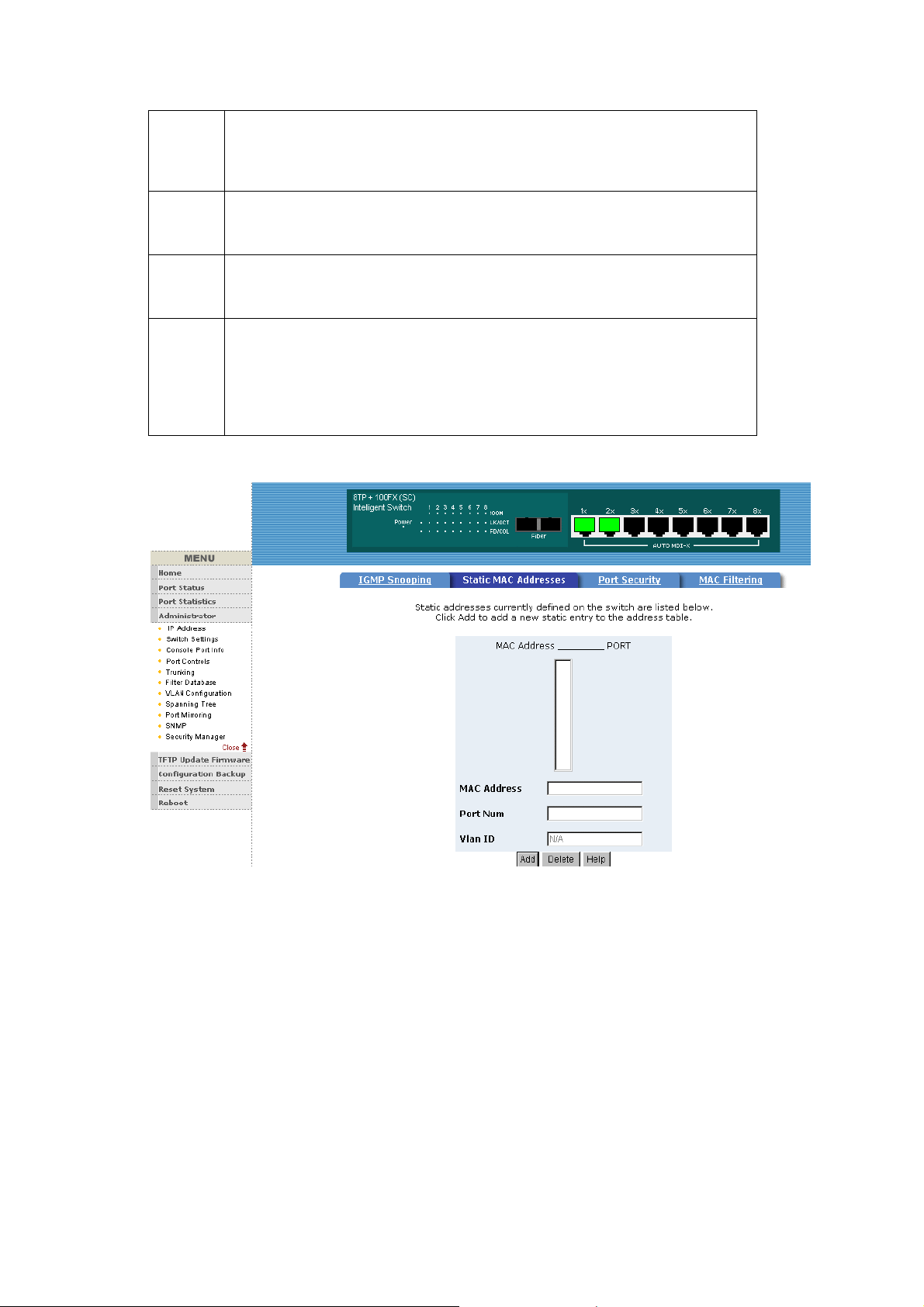
A message sent from the querier (IGMP router or switch) asking for a
ost to the querier to indicate that the host wants
A message sent by a host to the querier to indicate that the host has quit to
Mes
sag
e
Que
response from each host belonging to the multicast group.
ry
Rep
ort
Lea
ve
Gro
up
A message sent by a h
to be or is a member of a given group indicated in the report message.
be a member of a specific multicast group.
5-4-6-2. Static MAC Address
Description
When you add a static MAC address, it remains in the switch's address
table, regardless of whether the device is physically connected to the
switch. This saves the switch from having to re-learn a device's MAC
address when the disconnected or powered-off device is active on the
network again.
1. To add a static MAC address
2. From the main menu, click administrator, then click Filter Database.
66
Page 69
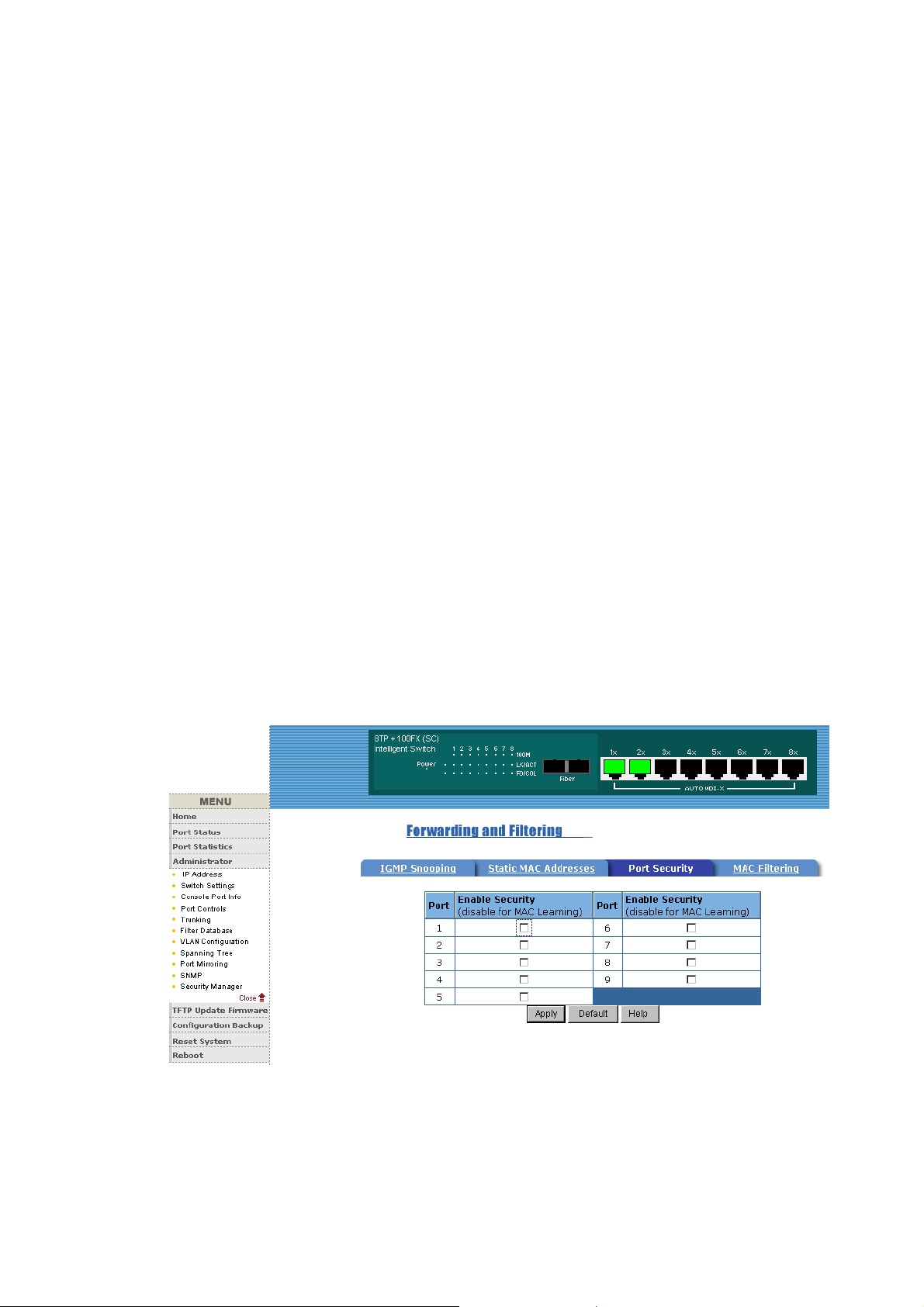
3. Click Static MAC Addresses. In the MAC address box, enter the MAC
address to and from which the port should permanently forward traffic,
regardless of the device's network activity.
4. In the Port Number box, select a port number.
5. If tag-based (IEEE 802.1Q) VLANs are set up on the switch, static
addresses are associated with individual VLANs. Type the VID
(tag-based VLANs) to associate with the MAC address.
6. Click add
5-4-6-3. Port Security
A port in security mode will be “locked” without permission of address
learning. Only the incoming packets with SMAC already existing in the
address table can be forwarded normally. User can disable the port from
learning any new MAC addresses, then use the static MAC addresses
screen to define a list of MAC addresses that can use the secure port.
Enter the settings, then click Submit to apply the changes on this page.
5-4-6-4. MAC Filtering
Page 70
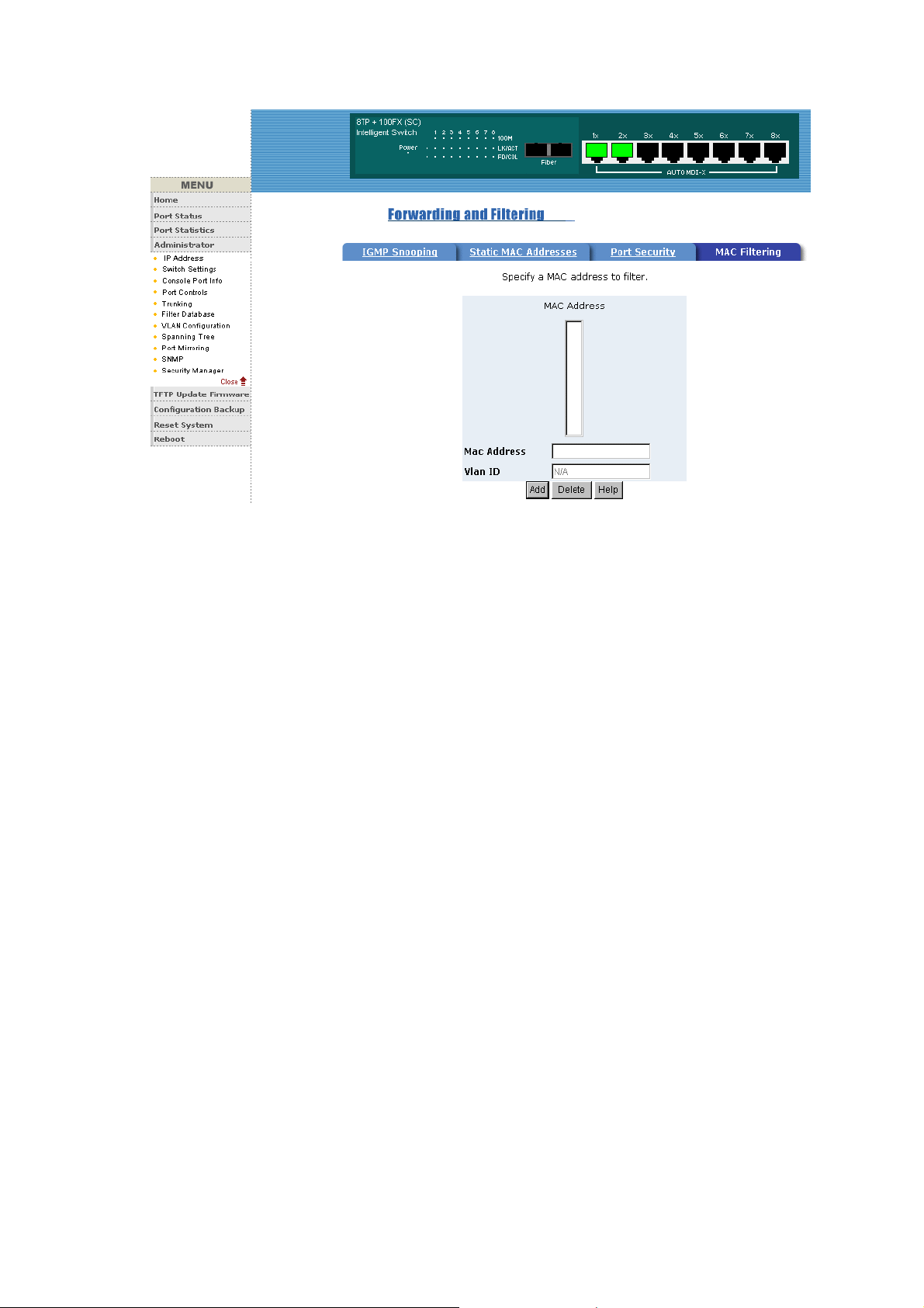
5-4-7. VLAN configuration
A Virtual LAN (VLAN) is a logical network grouping that limits the
broadcast domain. It allows you to isolate network traffic so only
members of the VLAN receive traffic from the same VLAN members.
Basically, creating a VLAN from a switch is logically equivalent of
reconnecting a group of network devices to another Layer 2 switch.
However, all the network devices are still plug into the same switch
physically.
The 8TP+1Fiber Management Switch support port-based and
protocol-base VLAN in web management page, In the default
configuration,
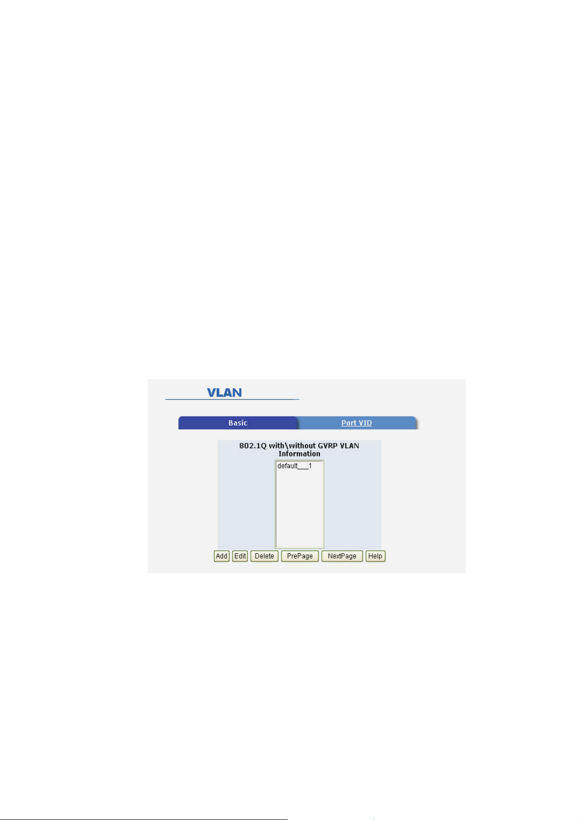
VLAN support is enable and all ports on the switch belong to default
VLAN, VID is 1.
NOTE: The default VLAN can’t be deleted.
68
Page 71
Support Port-based VLANs (IEEE 802.1Q VLAN)
Port-based Tagging rule VLAN is an IEEE 802.1Q specification
standard. Therefore, it is possible to create a VLAN across devices from
different switch venders. IEEE 802.1Q VLAN uses a technique to insert
a “tag” into the Ethernet frames. Tag contains a VLAN Identifier (VID)
that indicates the VLAN numbers.
Support Protocol-based VLAN
In order for an end station to send packets to different VLANs, it itself
has to be either capable of tagging packets it sends with VLAN tags or
attached to a VLAN-aware bridge that is capable of classifying and
tagging the packet with different VLAN ID based on not only default
PVID but also other information about the packet, such as the protocol.
5-4-7-1. Basic
Create a VLAN and add tagged member ports to it.
1. From the main menu, click administrator -- VLAN configuration.
2. Click Add
3. Type a name for the new VLAN.
4. Type a VID (between 2-4094). The default is 1.
Page 72
5. From the Available ports box, select ports to add to the switch and
click Add.
6. Click Apply
5-4-7-2. Port VID
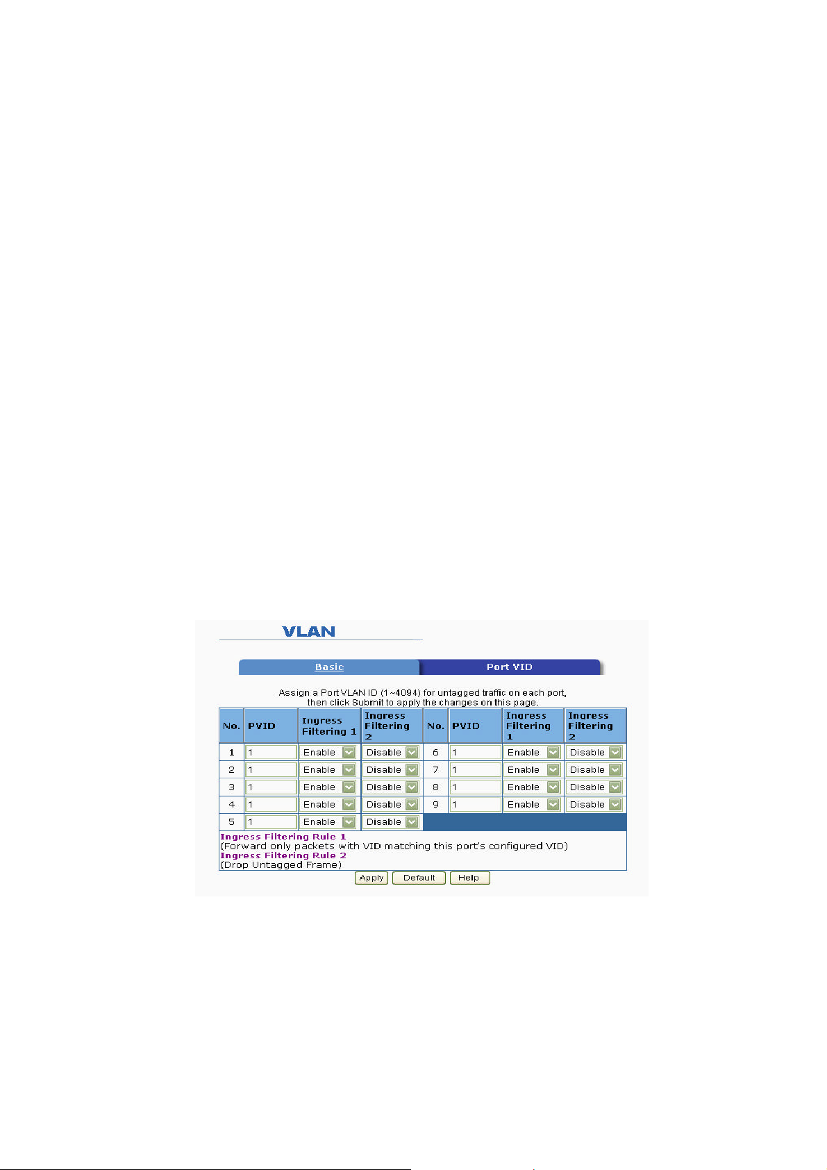
Configure port VID settings
From the main Tag-based (IEEE 802.1Q) VLAN page, click Port VID
Settings.
Port VID (PVID)
Sets the Port VLAN ID that will be assigned to untagged traffic on a
given port. For example, if port 9's Default PVID is 100, all untagged
packets on port 9 will belong to VLAN 100. The default setting for all
ports is VID 1.
This feature is useful for accommodating devices that you want to
participate in the VLAN but that don't support tagging. Only one
untagged VLAN is allowed per port.
Ingress Filtering
Ingress filtering lets frames belonging to a specific VLAN to be
forwarded if the port belongs to that VLAN. 8TP+1Fiber Management
Switch have two ingress filtering rule as follows:
Ingress Filtering Rule 1: Forward only packets with VID matching this
70
Page 73
port's configured VID .
Ingress Filtering Rule 2: Drop Untagged Frame.
5-4-8. Spanning Tree
The Spanning-Tree Protocol (STP) is a standardized method (IEEE
802.1D ) for avoiding loops in switched networks. When STP enabled,
to ensure that only one path at a time is active between any two nodes
on the network.
You can enable Spanning-Tree Protocol on web management’s switch
setting advanced item, select enable Spanning-Tree protocol. We are
recommended that you enable STP on all switches ensures a single
active path on the network.
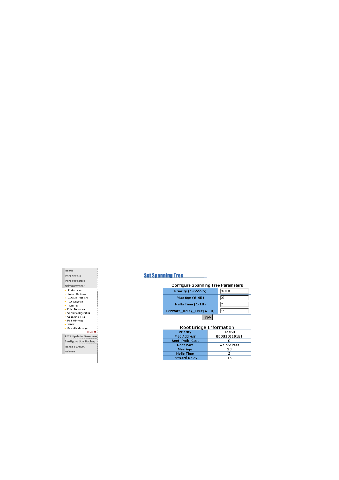
1. You can view spanning tree information about the Root Bridge.
Such as follow screen.
2. You can view spanning tree status about the switch. Such as
follow screen.
Page 74
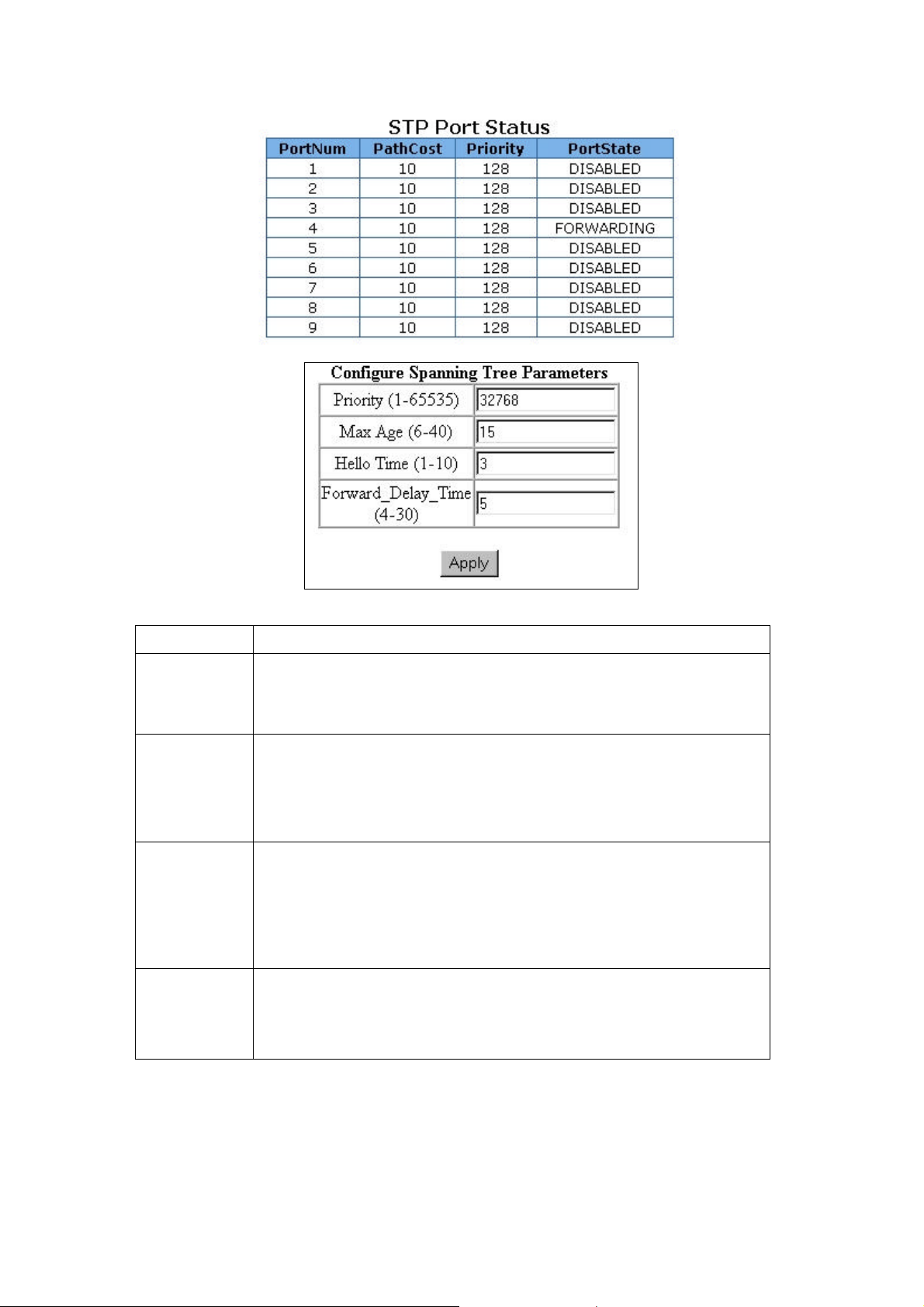
bridge. The bridge with the lowest value has the highest priority and is
The number of seconds a port
Prameter
Priority
Max Age
Hello
Time
Forward
Delay
time
Description
You can change priority value, A value used to identify the root
selected as the root. Enter a number 1 through 65535.
You can change Max Age value, The number of seconds a bridge
waits without receiving Spanning-Tree Protocol configuration
messages before attempting a reconfiguration. Enter a number 6
through 40.
You can change Hello time value, the number of seconds between
the transmission of Spanning-Tree Protocol configuration messages.
Enter a number 1 through 10.
You can change forward delay time,
waits before changing from its Spanning-Tree Protocol learning and
listening states to the forwarding state. Enter a number 4 through 30.
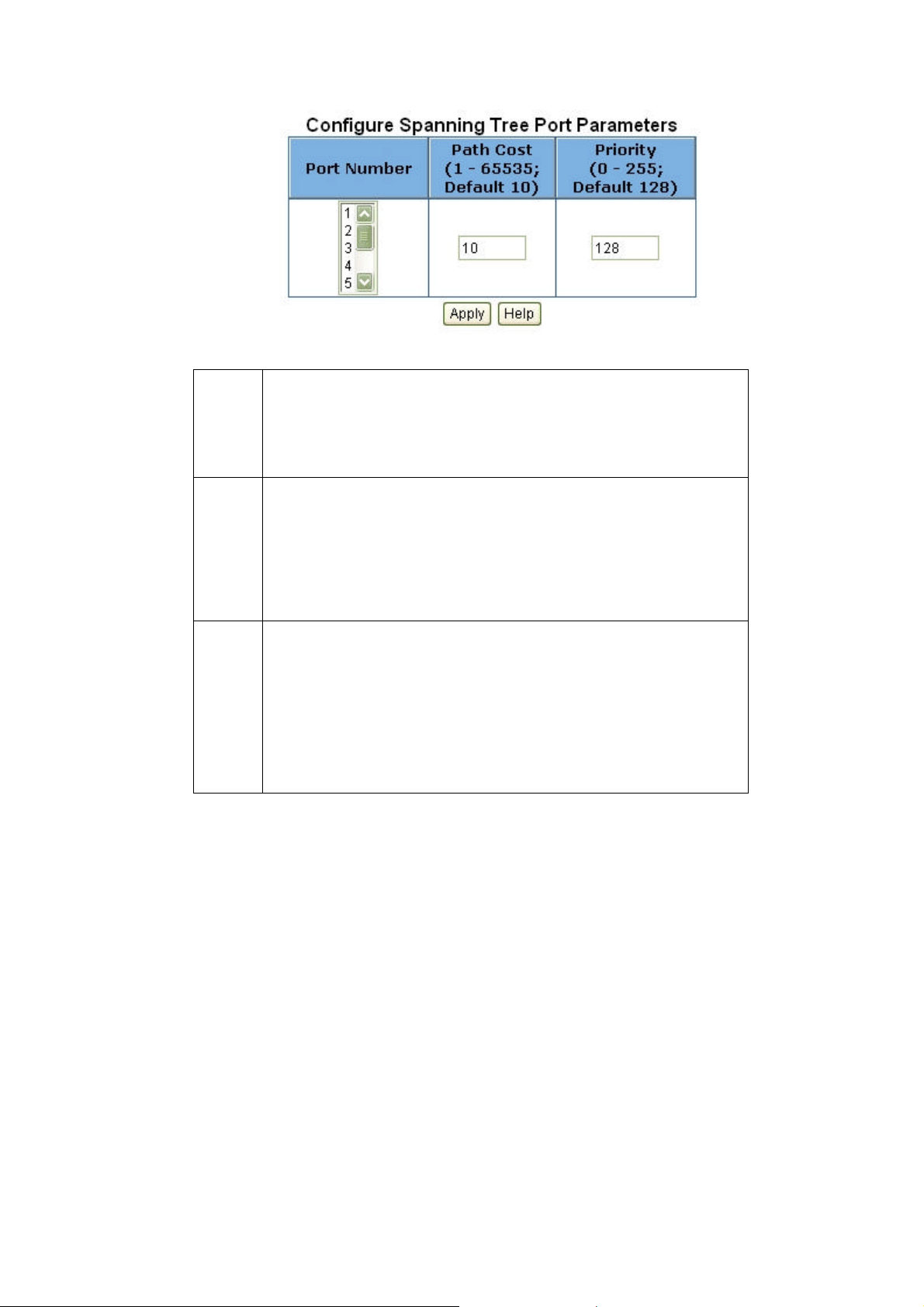
3. The following parameter can be configured on each port , click
set Apply button to modify .
72
Page 75
Par
am
ete
r
Por
t
Pri
orit
y
Pat
h
Co
st
You can make it more or less likely to become the root port, the
rage is 0-255,default setting is 128
the lowest number has the highest priority. If you change the value,
you must reboot the switch.
Specifies the path cost of the port that switch uses to determine
which port are the forwarding ports
the lowest number is forwarding ports, the rage is 1-65535
and default value base on IEEE802.1D
10Mb/s = 50-600 100Mb/s = 10-60
If you change the value, you must reboot the switch.
5-4-9. Port Mirror
Description
The Port Mirror is a method for monitor traffic in switched networks.
Traffic through ports can be monitored by one specific port. That is,
traffic goes in or out monitored ports will be duplicated into mirror port.
Page 76
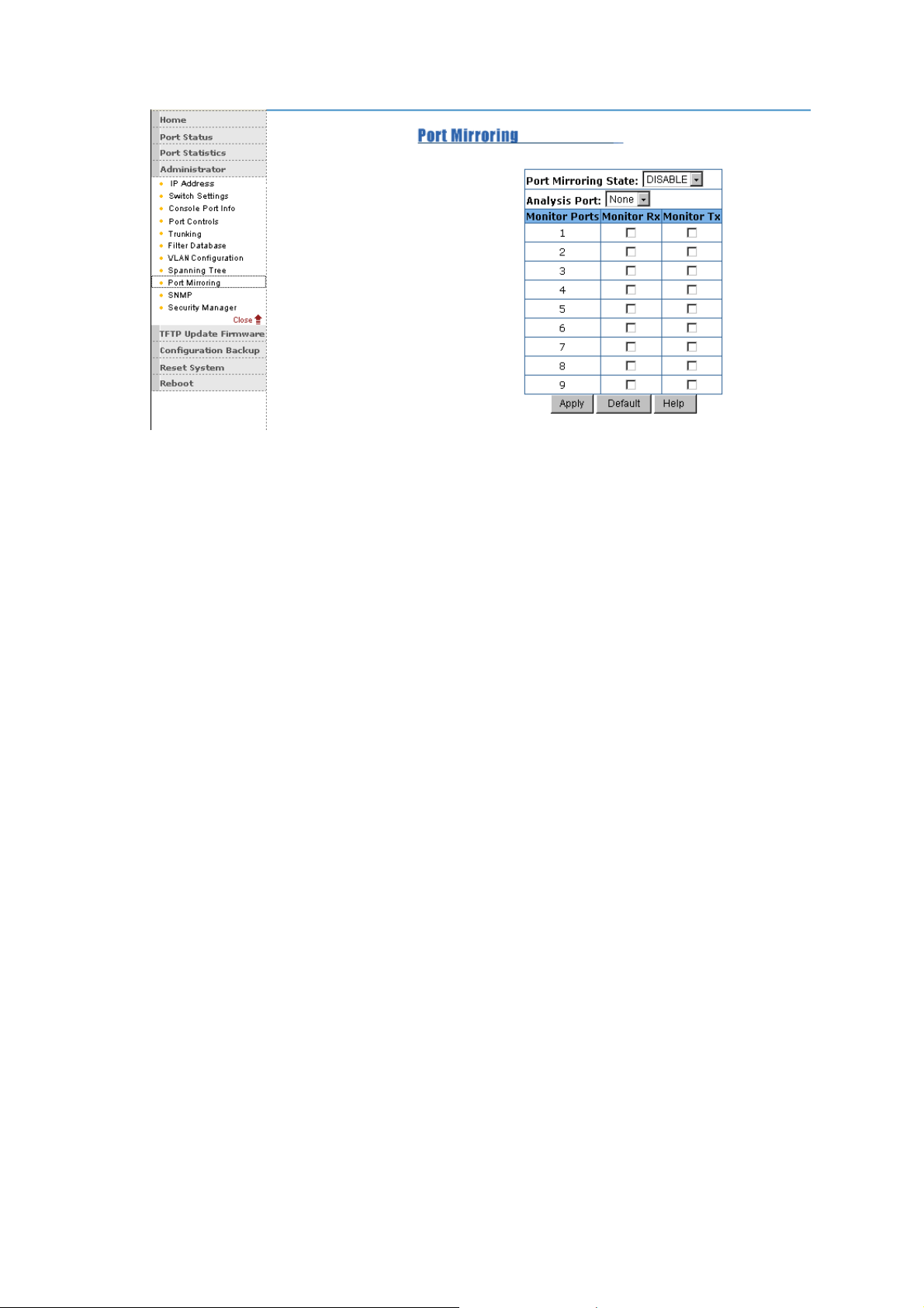
Roving Analysis State: Enable or disable the port mirror function.
Mirror Ports: The ports you want to mirror. All mirror port traffic will be
copied to mirror port. You can select max 9 monitor ports in the switch. If
you want to disable the function, you must select monitor port to none.
Monitor Rx: Monitored receive frames from the port.
Monitor Tx: Monitored send frames from the port.
5-4-10. SNMP
Any Network Management running the simple Network Management
Protocol (SNMP) can management the switch,
Provided the Management Information Base (MIB) is installed correctly
on the management station. The SNMP is a Protocol that governs the
transfer of information between management and agent. The
8TP+1Fiber Management Switch supports SNMP V1.
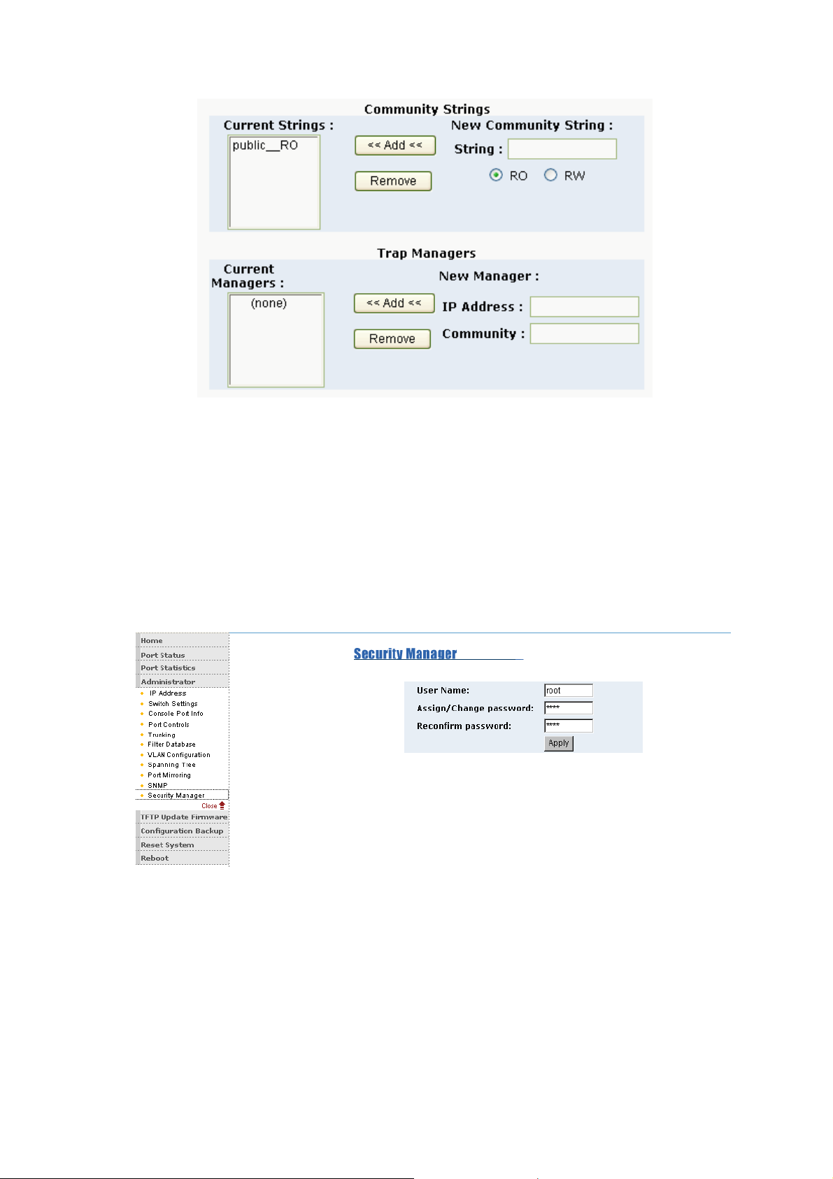
1. Use this page to define management stations as trap managers and to
enter SNMP community strings. User can also define a name, location,
and contact person for the switch. Fill in the system options data, then
click Apply to update the changes on this page
74
Page 77
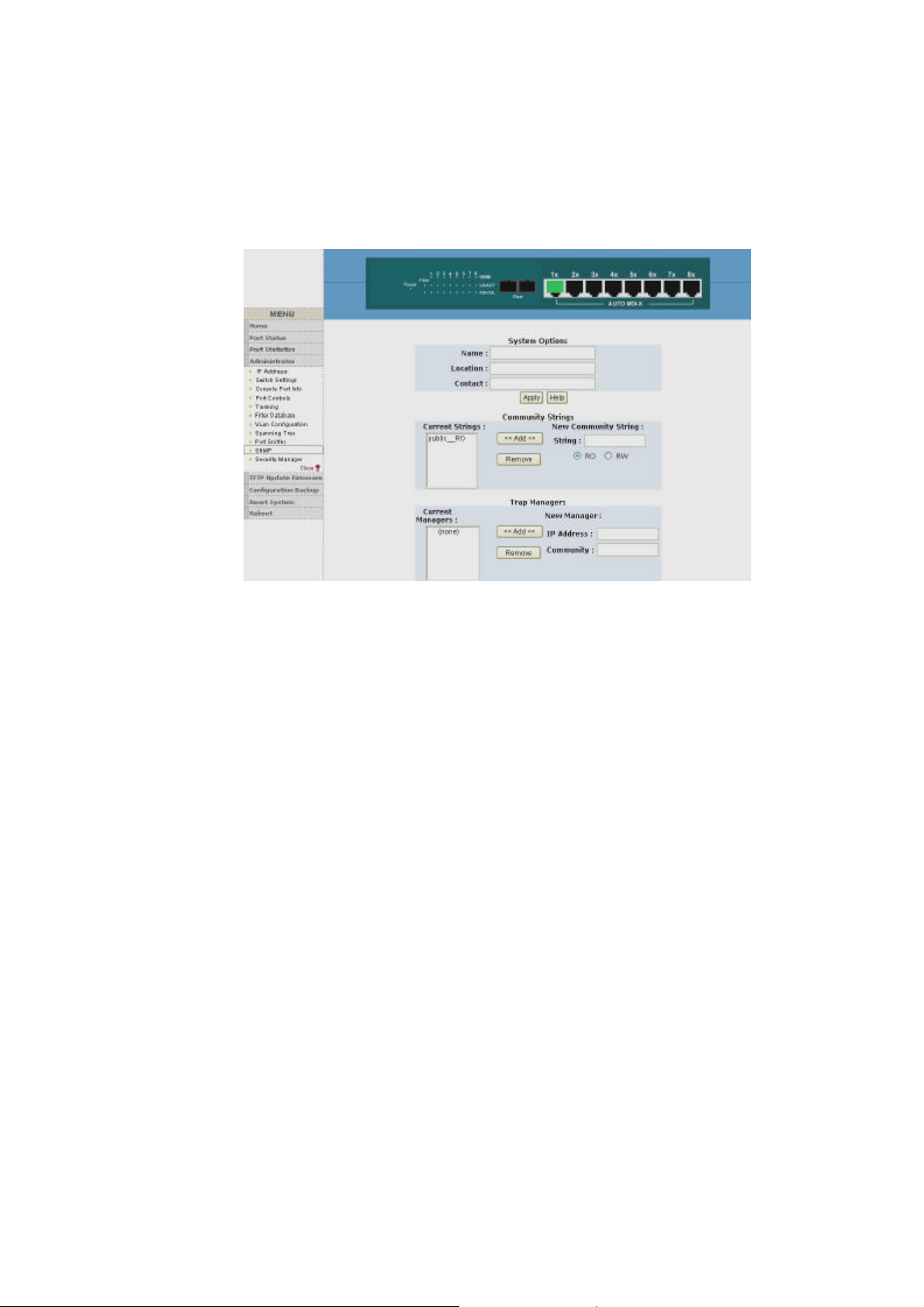
Name: Enter a name to be used for the switch.
Location: Enter the location of the switch.
Contact: Enter the name of a person or organization.
2. Community strings serve as passwords and can be entered as
one of the following:
Read only: Enables requests accompanied by this string to display
MIB-object information.
Read write: Enables requests accompanied by this string to display
MIB-object information and to set MIB objects.
3. Trap Manager
A trap manager is a management station that receives traps, the system
alerts generated by the switch. If no trap manager is defined, no traps
are issued. Create a trap manager by entering the IP address of the
station and a community string.
Page 78
5-4-11.Security Manager
1. Use this page, user can change web management user name and
password.
User name: root
Password: root
5-4-12. TFTP Update Firmware
1. The following menu options provide some system control
functions to allow a user to update
firmware and remote boot switch system:
76
Page 79
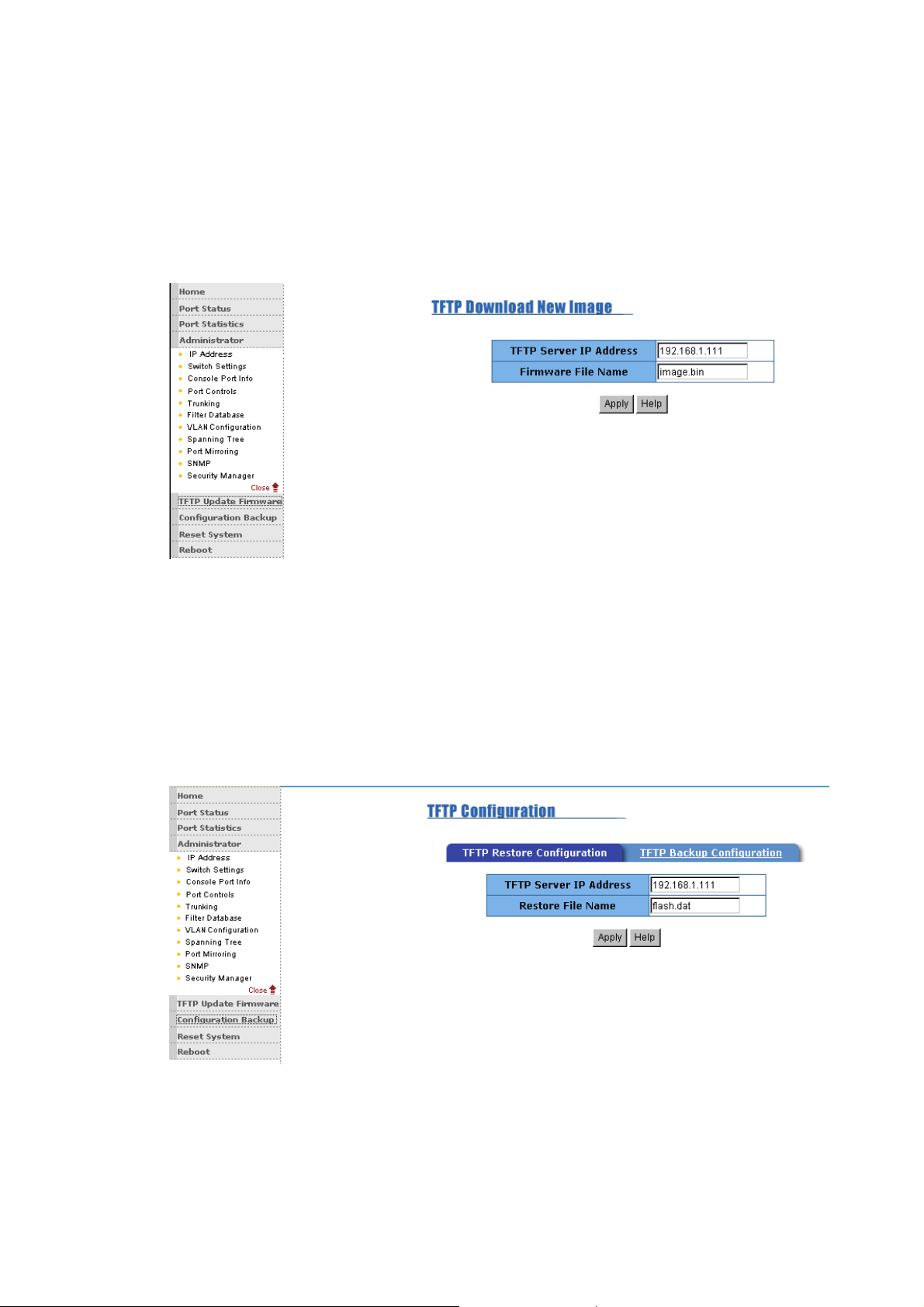
* Executing TFTP software
* Copy firmware update version image.bin to TFTP software directory.
* In web management select administrator— TFTP update firmware.
* Download new image.bin file then in web management press <update
firmware>.
5-4-13. Configuration Backup
5-4-13-1. TFTP Restore Configuration
Use this page to set TFTP server address. You can restore EEPROM
value from here, but you must put back image in TFTP server, switch
will download back flash image.
5-4-13-2. TFTP Backup Configuration
Use this page to set TFTP server IP address. You can save current
EEPROM value from here, then go to the TFTP restore configuration
Page 80
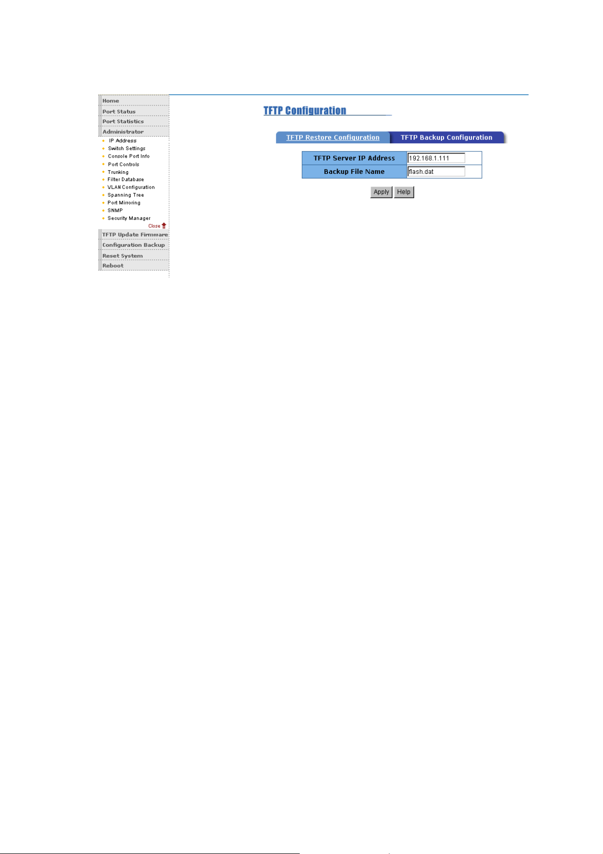
page to restore the EEPROM value.
78
Page 81
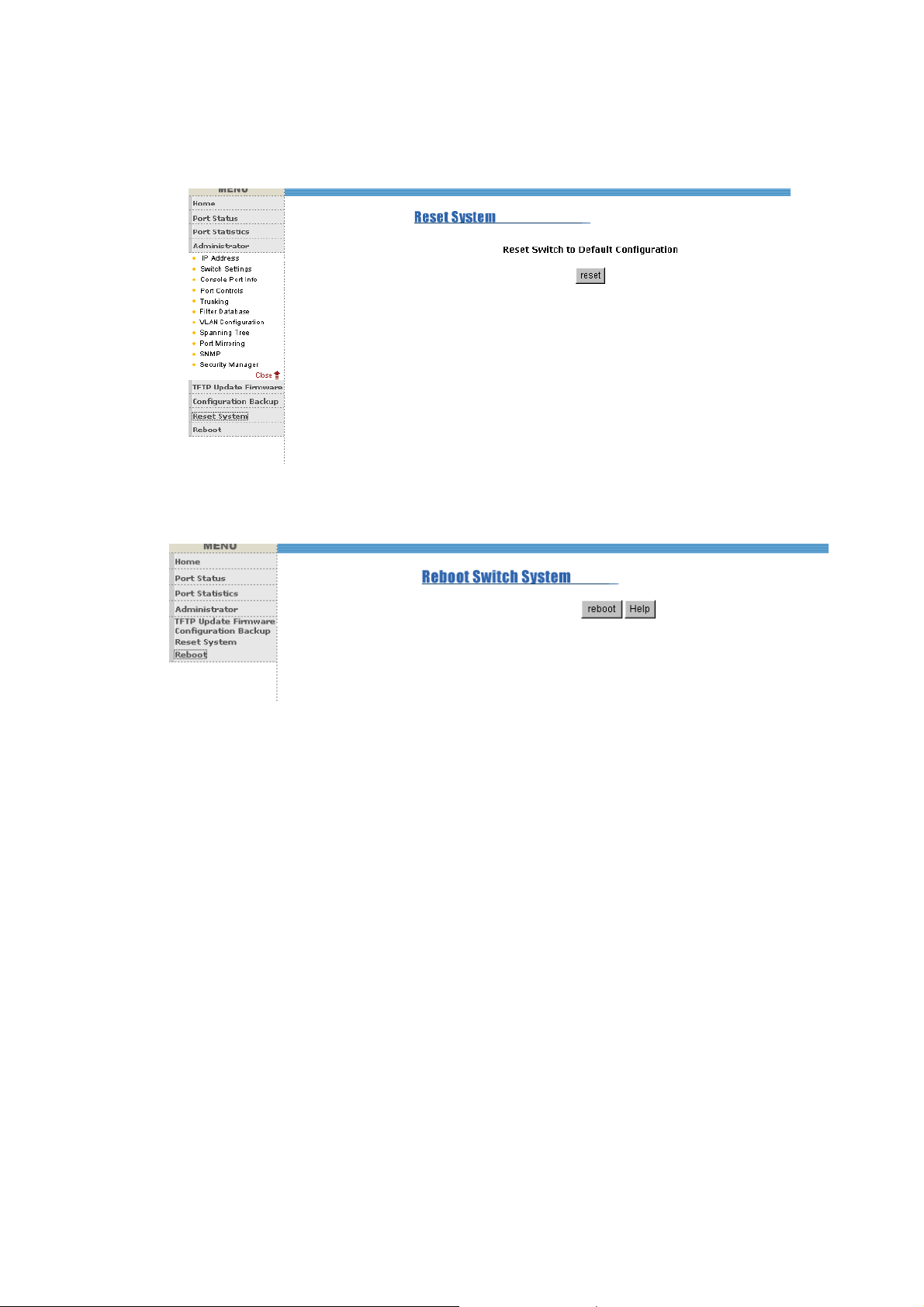
5-4-14. Reset System
Reset Switch to default configuration, default value as below
5-4-15. Reboot
Reboot the Switch in software reset.
Page 82

6. Technical Specifications
This section provides the specifications of the LB-FEA800M and the following
table lists the specifications.
IEEE802.3, 802.3u
IEEE802.3x Flow control and Back pressure
Standards
Compliance
Protocol CSMA/CD
Transfer Rate
LED Indicators
Network Cables UTP/STP Cable: 100Meters
MAC Address
IEEE802.1D Spanning Tree protocol
IEEE802.1Q VLAN Tagging
IEEE802.1p Class of Service
IEEE802.3ad Link aggregation
14880 packets per second for 10Mbps
148800 packets per second for 100Mbps
Per unit: Power
Per RJ-45 port: Link/Activity, 100Mbps, Full
duplex/Collision
8K MAC address Table
Data Buffer
Switch Fabric Bandwidth
Dimensions 250mm x 133mm x 37mm (L x W x H)
Weight 1070g
Storage Temp.
2Mbits
Non-blocking store-and-Forward, Up to
3.8Gbps
-40℃ to 70 ℃, Non condensing
80
Page 83

Operational Temp.
0℃ ~ 50℃
Power Supply 100~240VAC, 50/60 Hz
Power Consumption 15 Watts
EMI & Safety FCC A, CE, UL, cUL
Page 84

7. Troubleshooting
This section is intended to help you solve the most common problems on the
LB-FEA800M series.
Incorrect connections
n Faulty or loose cables
Look for loose or obviously faulty connections. If they appear to be OK,
make sure the connections are snug. IF that does not correct the
problem, try a different cable.
n Non-standard cables
Non-standard and miswired cables may cause numerous network
collisions and other network problem, and can seriously impair network
performance. A category 5 cable tester is a recommended tool for every
100Base-T network installation.
n Improper Network Topologies
It is important to make sure that you have a valid network topology.
Common topology faults include excessive cable length and too many
repeaters ( hubs ) between end nodes. In addition, you should make
sure that your network topology contains no data path loops. Between
any two ends nodes, there should be only one active cabling path at any
time. Data path loops will cause broadcast storms that will severely
impact your network performance.
82
Page 85

Diagnosing LED Indicators
The Switch can be easily monitored through panel indicators to assist in
identifying problems, which describes common problems you may
encounter and where you can find possible solutions.
IF the power indicator does not turn on when the power cord is plugged
in, you may have a problem with power outlet, or power cord. However,
if the Switch powers off after running for a while, check for loose power
connections, power losses or surges at power outlet. IF you still cannot
resolve the problem, contact your local dealer for assistance.
n Cabling
RJ-45 ports: Use unshielded twisted-pair (UTP) or shield twisted-pair
( STP ) cable for RJ-45 connections: 100Ω Category 3, 4 or 5 cable for
10Mbps connections or 100Ω Category 5 cable for 100Mbps
connections. Also be sure that the length of any twisted-pair connection
does not exceed 100 meters ( 328 feet ).
100Base-FX fiber port: Fiber multi-mode connector type must use
50/125 or 62.5/125 um multi-mode fiber cable. You can connect two
devices over a 2 kilometer distance. However, Fiber single-mode
connector type must use 9/125 um single- mode fiber cable. You can
connect two devices over a 15~60 kilometers distance in full duplex
operation.
 Loading...