


Pro
Weighing System
MANUAL
OPERATORS


Pro Weighing System
Model LR918
Document No. MAN-80664-00
Software No. 60270 Version 1.0
Issue Date: October 2002
Distributed Worldwide by:
93 First Avenue, PO Box 13-115, Tauranga, New Zealand
+64-7-5776034
℡ +64-7-5782820
info@loadrite.co.nz
www.loadritescales.com
Designed & Manufactured by:
8 Walls Road, PO Box 12-607, Penrose, Auckland, New Zealand
www.actronic.com
This manual is copyrighted with all rights reserved. Under copyright laws, this manual may not be
copied in whole or in part or reproduced in any other media without the express written permission
of Actronic Ltd. Permitted copies must carry the same proprietary and copyright notices as were
affixed to the original. Under the law, copying includes translation into another language.
Please note that while every effort has been made to ensure that the data given in this document is
accurate, the information, figures, illustrations, tables, specifications, and schematics contained
herein are subject to change without notice.
Actronic Ltd assumes no liability in connection with the use of any Loadrite branded product.
© 2002 ACTRONIC LIMITED


i
Contents
1 Introduction .........................................................................................................................1
Indicator Lights .............................................................................................................................................. 2
Keypad ............................................................................................................................................................ 2
2 Quick Start Guide ...............................................................................................................5
Switching On ................................................................................................................................................. 5
Standby............................................................................................................................................................ 5
The Warm Up Screen .................................................................................................................................. 5
The Ready Screen ......................................................................................................................................... 6
Weighing a Load ........................................................................................................................................... 6
Static Weigh function................................................................................................................................... 7
Adding a Load ............................................................................................................................................... 7
Clearing the Short Total............................................................................................................................... 8
Zeroing............................................................................................................................................................ 8
3 Weighing Overview........................................................................................................... 10
Weighing Modes......................................................................................................................................... 10
Short and Long Totals ................................................................................................................................11
Accurate Weighing..................................................................................................................................... 11
General Method of Weighing..................................................................................................................12
4 Weighing Procedures ........................................................................................................ 13
Adding a Load .............................................................................................................................................13
Auto Add....................................................................................................................................................... 14
Subtracting a Load...................................................................................................................................... 14
Zeroing.......................................................................................................................................................... 15
Recalling Last Load ..................................................................................................................................... 18
Viewing Long Total..................................................................................................................................... 19
Clearing Totals ............................................................................................................................................. 19
Tare Function ............................................................................................................................................... 21
5 Product Management .......................................................................................................23
6 Data ....................................................................................................................................25
Data Edit........................................................................................................................................................ 25
Automatic Data Prompt ............................................................................................................................ 30
Data Suspend............................................................................................................................................... 30
7 Target Mode.......................................................................................................................32
8 Batch Mode........................................................................................................................ 35
The Batch Screen ........................................................................................................................................ 36
Viewing the Current Recipe ..................................................................................................................... 37
Changing the Recipe.................................................................................................................................. 38
Entering the Batch Total ............................................................................................................................ 39
Batch Weighing ........................................................................................................................................... 40
Clearing the Batch Totals .......................................................................................................................... 41
Returning to Total Mode........................................................................................................................... 41
9 Mix Mode...........................................................................................................................42
The Mix Screen............................................................................................................................................ 43
Mix Weighing ..............................................................................................................................................43
Clearing the Mix Totals.............................................................................................................................. 45
Returning to Total Mode........................................................................................................................... 45
10 Blend Mode........................................................................................................................46
The Blend Screen........................................................................................................................................ 46

ii
Blend Weighing ...........................................................................................................................................47
11 Split Mode ..........................................................................................................................49
12 Tip Off.................................................................................................................................52
13 Menu Options....................................................................................................................56
Setup ..............................................................................................................................................................57
Clock Setting (Clock) ................................................................................................................................57
Changing Scale Number (Scale#) .......................................................................................................... 57
Clear All Long Totals (ClearAll) ................................................................................................................58
Auto Add On/Off Setting (Auto Add)....................................................................................................58
Rotary Trigger Position Screen (TrigScrn)..............................................................................................58
LD941 Data Module Properties (Module)...........................................................................................59
Data Edit (DataEdit) ....................................................................................................................................59
Data List (DataList)...................................................................................................................................... 60
Alarm Clock On/Off...................................................................................................................................61
Alarm Time Set ............................................................................................................................................61
Self Test (Selftest) ....................................................................................................................................... 62
Uplink (Uplink).............................................................................................................................................62
14 Print Functions...................................................................................................................63
Printed Data ................................................................................................................................................. 64
Print Menu ....................................................................................................................................................64
15 Obtaining the Best Accuracy............................................................................................70
Lifting Speed.................................................................................................................................................70
Trigger Point ................................................................................................................................................. 70
Bounce...........................................................................................................................................................70
Centre of Gravity.........................................................................................................................................70
16 Error Messages...................................................................................................................71
Bouncing Load.............................................................................................................................................71
Check Power................................................................................................................................................71
Check Transducer .......................................................................................................................................71
Check Trigger...............................................................................................................................................71
Check Zero................................................................................................................................................... 71
Lift Under Range ......................................................................................................................................... 72
Module Data Lost ....................................................................................................................................... 72
Module Error ................................................................................................................................................72
Module Full................................................................................................................................................... 72
No Lock.........................................................................................................................................................72
Over Target ..................................................................................................................................................72
Overload .......................................................................................................................................................73
Poor Lift .........................................................................................................................................................73
Printer Disabled ........................................................................................................................................... 73
Printer Error ..................................................................................................................................................73
Return Under Range...................................................................................................................................73
Speed Changed ...........................................................................................................................................74
Too Heavy, Zero Aborted......................................................................................................................... 74
Warm Up Lift................................................................................................................................................74
17 Specifications .....................................................................................................................75
18 Output / Input Connections.............................................................................................77
Appendix i Time and Date...........................................................................................................78
Appendix ii Span Calibration Adjustment..................................................................................81

LOADRITE PRO OPERATING MANUAL
1
1 Introduction
The Loadrite Weighing System measures the weight of loads lifted by frontend loaders, log loaders, forklift trucks and similar machines that use
hydraulic rams to lift the load. The Loadrite is installed in the cab of the
loading machine and is connected to sensors on the lifting arms.
As the machine raises the load, the Loadrite measures the hydraulic
pressure in the lift cylinders, converts pressure into a weight reading and
displays the result. An electronic trigger device mounted on the lift arms
ensures that the pressure readings are always taken at the same position
on every lift.
The weight of the bucket or forks and associated structures is zeroed out
when the system is calibrated so that only the weight of the payload is
displayed. While operating the loader, the driver can add each weight lifted
to a running total.
LCD display
Indicator lights
Keypad
Main Operating Keys

LOADRITE PRO OPERATING MANUAL
2
The Loadrite has internal memory which stores settings and production data
even when switched off.
Indicator Lights
Four indicator lights are provided below the LCD screen.
Trigger
Check
Auto-Add
Tip-Off
Trigger Illuminates when a load is lifted past the
trigger point. When this light is on, the lifted
weight may be added.
Pages 7
and 12
Check
Function
Illuminates when the Loadrite is in the userselected function. Possible options are
Interlock, Tare mode, and Safe-to-weigh
mode for rotary trigger. Configuration is set
during installation.
-
Auto-Add Illuminates when the Loadrite is in Auto-Add
mode. In this mode, the Loadrite will
automatically add the lifted weight.
Page 14
Tip-Off Illuminates when the Tip-Off function is
operating.
Page 52
Keypad
The table below shows the special functions that the keys have in addition
to their numeric values used for entering data.
Adjusts the brightness of the screen back light.
-
A B C
Displays time and date. -
+
L
D E F
Displays the long total for the current product. Page 19
G H I
Recalls the previous load. Page 18

LOADRITE PRO OPERATING MANUAL
3
J K L
Allows you to enter a tare weight. Page 21
M N O
Accesses the menu Page 56
P Q R S
Subtracts the current load from the total. Page 15
T U V
Toggle language. -
W X Y Z
Accesses conversion. -
View alarm settings. -
i
Decimal point. Also view system information. -
Enter key for accepting data or changes. -
Exits an operation without changing the data.
When pressed on the Ready screen, puts the
Loadrite into standby mode. To return to the
Ready screen, press any key.
-
Allows you to enter additional Data. Page 25
Scroll down. Also enter Total mode. Page 10
Scroll up. Also enter Target mode. Page 32
Scroll left. Also selects the Print functions. Page 64
Scroll right. Also change Product. Page 23
Tip-off weighing. Page 52

LOADRITE PRO OPERATING MANUAL
4
Adds the current load to the total. Also toggles
into Auto Add mode.
Page 13
Clears the short total for the current product. Page 19
Zeroes out the current load. Page 15

LOADRITE PRO OPERATING MANUAL
5
2 Quick Start Guide
This section summarises the common Loadrite procedures. For full details
of weighing methods, see Weighing Overview on page 10 and Weighing
Procedures on page 13.
Switching On
The Loadrite powers up automatically when you switch on the ignition of the
loading machine.
If the Loadrite has been switched off for more than 1 hour, it displays the
Warm Up screen when powered up.
Standby
The Loadrite has a ‘standby’ mode which is similar to turning the Loadrite
off.
To put the Loadrite into standby press
, the EXIT key, when in the Ready
mode.
To restart the Loadrite, press any key.
Standby
The Warm Up Screen
For best weighing accuracy, the hydraulic fluid in the lift cylinders should be
at normal operating temperature. This is achieved by raising and lowering
the empty bucket or forks a few times.
The Warm up screen is displayed if the machine has been turned off over
an hour.
Raise the empty bucket or forks past the
trigger point three times.
Warm up
Lift 3
The Loadrite beeps at each lift and
displays the count down from 3. After the
third lift, the Ready screen is displayed
and the screen may look like this.
Ready
Sand
0

LOADRITE PRO OPERATING MANUAL
6
If it is time to check zero, the Loadrite will
display the Check Zero message to
remind you.
More information about Ready screen and
Check Zero screen will be covered later
in this manual.
Check
Zero
The Ready Screen
The Ready screen shows the product name and the short total for that
product. The short total is simply the sum of loads since you last cleared
the total.
When the Ready screen is displayed, the Loadrite is in Total mode and is
ready to weigh. Note that Sand in the below example represents the
current product of choice. Your Loadrite may be configured differently, and
hence, a different product name may appear on the screen.
Ready
Sand
3400
The Loadrite is ready to weigh
Current product to be loaded
Current total loaded
Weighing a Load
(Weights shown are examples only)
Loadrite is ready to
weigh sand.
(Current total 3400)
Ready
Sand
3400
Raise the load
smoothly past the
trigger point using
normal engine revs.
The bucket must be
fully rolled back
during weighing.
Weighing
3400

LOADRITE PRO OPERATING MANUAL
7
A short time later,
the Loadrite beeps,
turns the TRIG
indicator light on
and displays the
load lifted (2200).
Sand
3400
2200
The trigger point is where the metal plate passes the body of the trigger.
Static Weigh function
The Loadrite has an option known as ‘Static Weigh’. When this is used, the
weight display is always ‘live’ and no trigger is used.
The ‘Trigger’ light is used to indicate that the weight being measured is
‘stable’ (not changing too much) and therefore can be Added, Subtracted or
Zeroed.
Your Loadrite dealer will have configured the Static Weigh function if
required. Other functions described in this manual operate in a similar
manner, regardless of whether Static Weigh is being used.
Adding a Load
(Weights shown are examples only)
Before lifting:
(Current total 5600)
Ready
Sand
5600
Raise the load smoothly past the trigger
point using normal engine revs.
The Loadrite beeps and displays the load.
(Weight of load 2200)
Sand
5600
2200
Press .
The Loadrite updates the total and returns
to the Ready state.
(New total 7800)
Ready
Sand
7800

LOADRITE PRO OPERATING MANUAL
8
Clearing the Short Total
(Weights shown are examples only)
When you want to reset the short total to
zero (e.g. after loading a truck) ready for
another loading operation,
Press .
Ready
Sand
7800
The Loadrite displays Total Cleared for
a few seconds, clears the short total for the
current product and then …
Total
Cleared
7800
…returns to the Ready screen.
Ready
Sand
0
Zeroing
It is required to zero the Loadrite from time to time. This is to avoid
inaccurate readings due to build up of material in the bucket.
(Weights shown are examples only)
Before lifting:
Make sure that the bucket is empty and
fully rolled back.
Ready
Sand
0
Raise the bucket smoothly past the trigger
point.
The Loadrite beeps and displays the load.
Sand
0
20

LOADRITE PRO OPERATING MANUAL
9
Press .
The Loadrite performs the zero adjustment
and returns to the Ready state.
Ready
Sand
0
More detailed information about Zeroing can be found on page 15.

LOADRITE PRO OPERATING MANUAL
10
3 Weighing Overview
Weighing Modes
While individual bucket weight can be measured, the Loadrite also has an
ability to accumulate how much weight you have loaded on to a truck. The
main weighing modes are shown in the following table. The modes that are
available in a particular Loadrite depend on the installation.
Mode Description
Total As you add bucket loads, the weights are added to the totals.
The short total is displayed.
Target A target weight is entered into the Loadrite. As you add bucket
loads, the remaining value to reach the target is displayed.
Batch Allows you to weigh and load different products according to a
predefined recipe that specifies the required proportions. You
enter the grand batch target. Loadrite will work out individual
product weights needed.
Mix Similar to Batch mode except that the grand target is not
required. You load the first product to a certain amount.
Loadrite will work out how much you need for the other
products in the mix, based on the predefined recipe.
Blend Allows you to load fixed numbers of bucketful's of different
products according to a predefined recipe.
The normal mode of operation is Total mode, which uses the Ready
screen. To return to Total mode from any of the other modes, press
.
For Batch/Mix/Blend mode, you will return to Total mode when you clear the
grand total, or when you select a product that is not in the recipe.
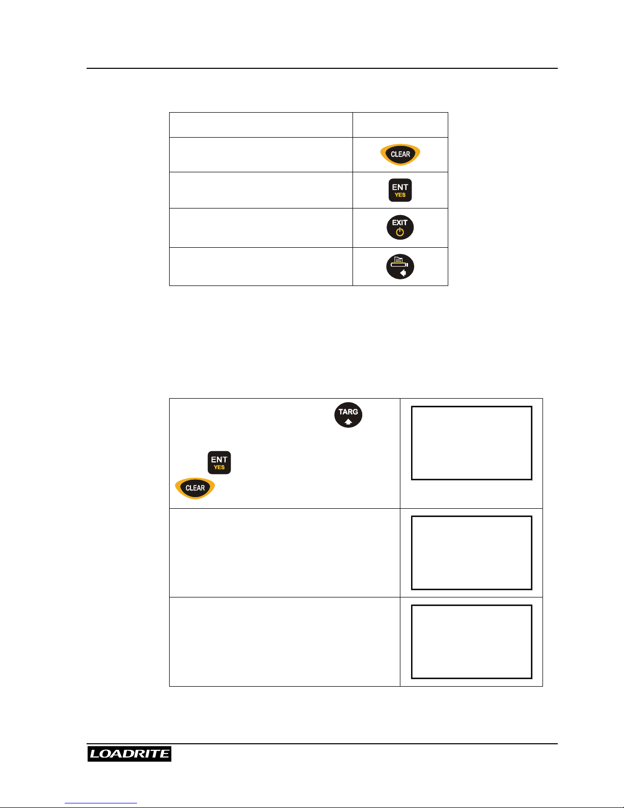
Changing to Target, Batch, Mix or Blend mode
If more than one of the above modes are enabled, you must first select the
mode you want to enter.

LOADRITE PRO OPERATING MANUAL
11
From the Ready screen, press .
Press 5 6 to scroll to the required mode
and then …
Target
Mode?
… press to accept.
Note: if your Loadrite has only one of
Target, Batch or Blend mode, there is no
need to scroll - simply press to
access the required mode.
Batch
Mode?
Short and Long Totals
The Loadrite keeps a total of the bucket weights that you add. For each
product, two independent totals are stored.
Short Total
Typically used to display the total weight lifted
onto a truck.
As you add successive loads, the Loadrite
displays the updated Short Total (sum of the
loads so far) on the Ready screen.
Long Total
Typically used to accumulate the weights lifted
over a longer period, for example a shift or a
day.
To view the Long Total, press
+
L
D E F
.
(See page 19.)
Accurate Weighing
For accurate weighing, make sure that:
• The bucket or forks are fully rolled back for each lift.
• The loader is stationary (for best accuracy).
• The lift arms start well below the trigger point. This ensures that all
acceleration and load bounce has been eliminated well before the
weighing sequence begins.
• The Loadrite is correctly zeroed. (Zeroing is described on page 15).

LOADRITE PRO OPERATING MANUAL
12
General Method of Weighing
1. BUCKET BACK. After picking up material into the bucket, roll the
bucket back.
2. LIFT. Raise the load smoothly past the trigger point using normal
engine revs. (The trigger point is where the metal plate passes the
body of the trigger). For best results, operate the lift lever before
accelerating the engine so that the machine does not rock as it lifts.
The Loadrite beeps, turns the TRIG light on and displays the load.
(See also page 6).
3. ADD. The Loadrite waits for a few seconds for you to take one of the
following actions:
• Press to add the weight to the long and short totals, or
• Press
P Q R S
to subtract the load from the totals, or
• Press to zero the measuring system.
If you don’t press a key, the Loadrite beeps and prompts you to take
action. The Loadrite then counts down and if you still don't press a
key, it discards the weight and goes back to the Ready state.

LOADRITE PRO OPERATING MANUAL
13
4 Weighing Procedures
Adding a Load
This function adds the lifted weight to the short and long totals for the
current product.
To Add a load
(Weights shown are examples only)
Before the load is lifted:
(Current total 5600)
Ready
Sand
5600
Raise the load smoothly past the trigger
point.
The Loadrite beeps and displays the load.
(Weight of load 2200)
Sand
5600
2200
Press .
The Loadrite updates the total and returns
to the Ready state.
(New total 7800)
Ready
Sand
7800
The Loadrite has an option to use a remote add button. If fitted, the remote
add button is normally mounted on the lift lever.
In Target mode, the display is different. For details, see Target Mode on
page 32.

LOADRITE PRO OPERATING MANUAL
14
Auto Add
Auto Add is an optional feature that is selected during installation. If Auto
Add is enabled, the Loadrite can automatically operate the ADD function
every time a load is lifted past the trigger point.
The Auto Add indicator light illuminates
when the Loadrite is in Auto-Add mode.
Ready
Sand
5600
To turn on/off auto add function
1. Press
M N O
to access user menu.
2. Use 5 6 to scroll to Auto Add.
3. Press to select.
4. Use 5 6 to adjust the setting.
5. Press to accept the setting.
If Auto Add is on:
• The procedure for zeroing is different. See page 17.
Subtracting a Load
This function can be useful when only part of a final bucket load of loose
material is required. You can add the full bucket load and then re-weigh
and subtract the amount remaining in the bucket.
Another example is when a log has been added and then removed from a
truck.

LOADRITE PRO OPERATING MANUAL
15
To subtract a Load
(Weights shown are examples only)
Before the load Is lifted:
(Current total 5600)
Ready
Sand
5600
Raise the load smoothly past the trigger
point.
The Loadrite beeps and displays the load.
(Weight of load 2200)
Sand
5600
2200
Press
P Q R S
.
The Loadrite updates the total and returns
to the Ready state.
(New total 3400)
Ready
Sand
3400
In Target mode, the display is different. For details, see Target Mode on
page 32.
Zeroing
When you raise an empty bucket past the trigger point, the display should
read zero. However, due to build up of material in the bucket, a small zero
error may occur.
Zero error affects the accuracy of lifted weights.
To zero the Loadrite
Before lifting:
Make sure that the bucket is empty and
fully rolled back.
The loader must be on level ground.
Ready
Sand
0

LOADRITE PRO OPERATING MANUAL
16
Raise the bucket smoothly past the trigger
point using normal engine revs.
The Loadrite beeps and displays the load.
(Example weight 20)
Sand
0
20
Press the key.
The Loadrite performs the zero adjustment
and returns to the Ready state.
Ready
Sand
0
Large ZERO Error
If the weight is greater than 5% of full scale, when you press , the
Loadrite prompts Bucket Empty? If it is, press ENT which will zero the
empty bucket. Pressing EXIT will not zero the scale
If the weight is greater than 10% of full scale, when you press , the
Loadrite displays Too heavy, zero aborted and does not alter any
settings.
This prevents any accidental zeroing of valid weights.
If the bucket is empty and this message still occurs, there may be a fault in
the system. The Loadrite should be checked and, if necessary, recalibrated.
Check Zero Prompt
Check
Zero
This function automatically reminds the operator to check ZERO
occasionally. Changes in the ZERO occur more often while the machine is
warming up.
When first turned on, after having been off for more than one hour, the
Loadrite will remind the operator to do a ZERO check:
• Every 15 minutes for the first hour
• Every 30 minutes thereafter

LOADRITE PRO OPERATING MANUAL
17
At this point a ZERO check lift should be carried out as described in the
previous section.
The reminder can be cleared without doing a ZERO check, by simply
continuing with normal operation. However, a ZERO error can affect the
accuracy of lifted weights so it is important to do a ZERO check regularly.
The automatic CHECK ZERO reminder will not occur if the operator is
checking the ZERO often enough.
The automatic CHECK ZERO prompt is an optional function that is selected
during installation.
Zeroing when Auto Add is On
The procedure to zero may be different when Auto Add is on and Auto Add
Time is set to 0. If this is how your Loadrite is configured, you will need to
carry out the following procedure:
Before lifting:
Press the key.
Zero
Lift
Raise the empty bucket smoothly past the
trigger point. The Loadrite beeps and
performs the zero adjustment.
Zero
Updated
If Auto Add is not on, or Auto Add Time is not set to 0, follow the standard
procedure to zero (page 15).
Auto-Add is described on page 14.

LOADRITE PRO OPERATING MANUAL
18
Recalling Last Load
The Recall function is equivalent to lifting the same load again and can be
used to correct mistakes.
You can recall and display the last load if it has been:
• Added
• Subtracted, or
• Timed out (ignored).
To Recall the previously lifted weight
(Weights shown are examples only)
Current total 5600.
Press
G H I
.
Ready
Sand
5600
The Loadrite beeps and displays the last
load.
(Weight of last load 2200)
Sand
5600
2200
If the last action was an “add”, you can
subtract.
If the last action was a “subtract”, you can
add.
(Example: subtracting a load that was
previously added, new total 3400)
Ready
Sand
3400
If you press a key that is not allowed in the circumstances, such as
when the recalled load was previously added, the Loadrite ignores the key
press.

LOADRITE PRO OPERATING MANUAL
19
Viewing Long Total
To view the Long Total for the current product
(Weights shown are examples only)
In Ready screen, press
+
L
D E F
.
After a few seconds, the Loadrite
automatically returns to the Ready screen.
Long Tot
23400
Clearing Totals
To clear the Short Total for the current product
(Weights shown are examples only)
In the Ready mode,
press .
Ready
Sand
7800
The Loadrite displays Total Cleared for
a few seconds, clears the Short Total for
the current product and then …
Total
Cleared
7800
… returns to the Ready screen.
The next ADD operation starts a new Short
Total for this product.
Ready
Sand
0

LOADRITE PRO OPERATING MANUAL
20
To clear the Long Total for the current product
(Weights shown are examples only)
In the Ready mode,
Press
+
L
D E F
.
The Loadrite displays the Long Total.
Long Tot
23400
Press .
The Loadrite asks you to confirm the clear
Long Tot
Clear?
23400
Press to confirm.
The Loadrite displays Long Tot
Cleared for a few seconds and then
returns to the Ready screen.
Note that the Short Total is also cleared for
consistency.
Ready
Sand
0
To clear all Long Totals in one go
Press
M N O
to display the menu and use
5 6
to scroll to the Clear All screen.
Press .
Menu
ClearAll
The Loadrite displays a prompt for you to
confirm the clear operation.
Press
again to clear all totals or
to return to the menu without clearing.
ClearAll
ENT/EXIT
If the Loadrite has a printer connected, the Long Totals are printed together
with a grand total before being cleared.

LOADRITE PRO OPERATING MANUAL
21
Tare Function
The Loadrite has two ways of using Tare and this is selected at time of
installation. The Tare can work either with the lifted weight, or the total
weight. This is explained in more detail below.
Your Loadrite dealer will set up how Tare is to operate with your machine.
Tare on Lifted weight
In this mode, the Tare function can be used, for example, to allow for the
weight of a pallet. When weighing, the Loadrite automatically deducts the
tare from the lifted weight and displays the net weight of the load.
Tare on Total weight
In this mode the entered Tare value is applied to the displayed Total value.
The Loadrite automatically adds the total for the currently product to the
Tare value and displays this value.
This mode if useful when loading vehicles which display their Tare weight
and maximum weight. The operator enters the Tare value into the Loadrite,
then loads the vehicle until the displayed total is equal to the vehicles
maximum loaded weight.
Entering a Tare weight using the keypad
You can enter a tare using the keypad or by measuring the weight. To enter
a Tare with the keypad, do the following steps. (When Tare is set to work on
the Total, the Tare value is normally entered with the keypad).
Press
J K L
.
Tare?
0
Key in the tare weight and press to
accept.
Tare?
50

LOADRITE PRO OPERATING MANUAL
22
Measuring a Tare weight
A Tare weight can be measured by the Loadrite. This is common when
finding the Tare weight of a pallet on the forks of a loader. (It is not normal
to measure the Tare weight when the Tare value is set to work on the
Total).
Lift the empty pallet past the trigger point.
The Loadrite beeps and displays the
weight.
Sand
0
50
Press
J K L
.
The Loadrite displays the measured weight
on the Tare screen.
Tare?
50
If necessary, edit the weight using the
keypad. Press to accept.
To turn on the function, enter a tare weight. To turn it off, enter a tare of
zero.

LOADRITE PRO OPERATING MANUAL
23
5 Product Management
Loadrite supports up to 30 products. Each product is associated with a
product number, product name, short total, long total and add bucket
counter. The product info screen enables you to manage your products.
The product info screen not only allows you to select a different product, but
also displays information about the product before you select it.
To select a different product
(Weights and product names are examples only.)
Ready screen:
Press .
Ready
Sand
3400
The Loadrite will first display the product
number along with the product name.
Then, the Short Total and the number of
buckets added will follow.
Product index = 1
Product name = Sand
Bucket added = 4
Short total = 3400
PROD01
Sand
Sand
Add# 4
3400
Press
56
to scroll through the products,
or key in a product number directly.
PROD02
Gravel
Gravel
Add# 0
0

LOADRITE PRO OPERATING MANUAL
24
Press to select the product and return
to the Ready screen.
Ready
Gravel
0

LOADRITE PRO OPERATING MANUAL
25
6 Data
If this feature is enabled, the Loadrite allows you to enter five data fields (up
to eight characters) that provide additional information to the weight data.
Each field has a label to identify it and can be configured as a specific data
type (e.g. alphanumeric, numeric or auto-increment). The specific labels
and data type for your Loadrite are set up at installation time.
Typical labels might be, for example:
Customer for Data 1
Docket for Data 2
Truck for Data 3
If you have the appropriate equipment installed, this information can be
stored in the LD940 MMS data logger and/or printed with the weight data.
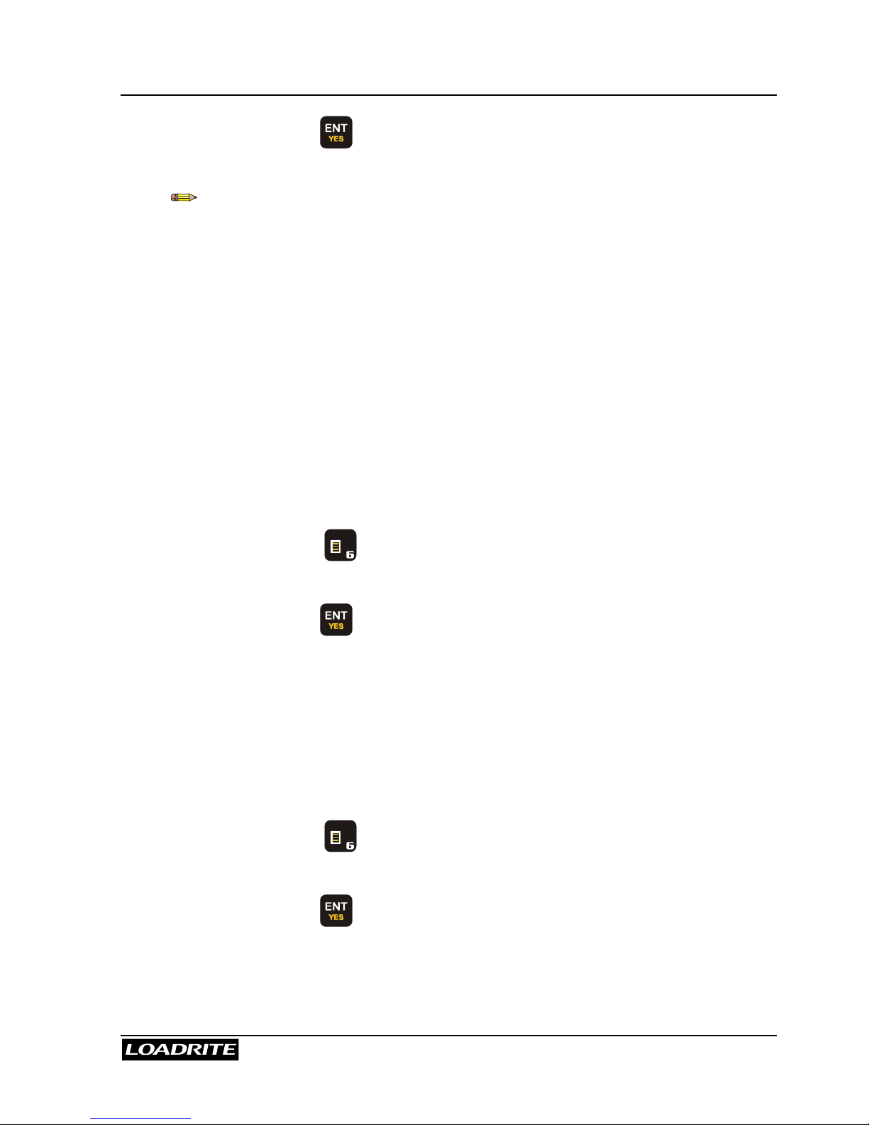
Data Edit
Before loading a truck, for example, you can enter the data as follows.
In Ready mode,
press . The Loadrite displays the first
field and prompts you to enter a value.
Customer
0
Suppose the customer is 1234
A B C
+
L
D E F
G H I
Note that pressing means accepting
the displayed value for the data field.
Customer
The Loadrite automatically displays the
next data field and prompts you to enter a
value.
Docket
0
Loadrite will automatically return to the
Ready screen, as soon as all data fields
have been accepted.

LOADRITE PRO OPERATING MANUAL
26
You may have up to five data fields available, depending on how the
Loadrite has been set up at installation time.
Alphanumeric Data
The Loadrite has an option to enter Alphanumeric (Alpha) data. This option
is enabled at installation time. The Loadrite uses its telephone style keypad
to allow letters to be entered.
When a number key is pressed, a digit is displayed. If the same number key
is pressed again, the first letter on that key is displayed. If the key is
pressed again the second letter is displayed and so on. For example, if the
A B C
key is pressed repeatedly, the characters displayed in sequence are
‘2’, ‘A’, ‘B’, ‘C’, ‘a’, ‘b’, ‘c’, ‘2’, ‘A’ and so on.
In this way names can be entered for customers, trucks etc.
Sometimes a name will have two sequential letters on the same key. For
example the letters ‘D’ and ‘E’ in the word ‘DEAKON. After the ‘D’ has been
entered (by pressing the
+
L
D E F
key twice), wait a second or two. The cursor
will automatically shift and be ready for your next character. You can then
enter 'E' by pressing the
+
L
D E F
key again.
Name Speed Dial and Scrolling
The Loadrite keeps a list of names for the data fields i.e. Customer List.
You can either use 5 6 keys to scroll through the list, or dial the index to
the list to recall the name.
Suppose we have a customer list as follows:
Joe
Deakon
Smith
Johnson
Adams
Use scrolling to recall Smith:
• Press
• Press
56
until you see Smith on the screen, then press

LOADRITE PRO OPERATING MANUAL
27
Use speed dial to recall Smith:
• Press
• You can press
+
L
D E F
(the 3rd name on the list), then
The data list can be printed out via Print Function: Print Data List as
described on page 68.
Name speed dial requires the Data Index option to be enabled at
installation.
Data List (name list) will not store names starting with numbers, if name
speed dial function is in active (Data Index option is enabled).
Auto target value look up
This function enables you to store a list of target values (for different trucks).
You can recall the target value from memory by either entering a number or
scrolling through a list of truck names.
Use scrolling to recall truck target value:
Suppose we have a truck and target list as follows. We configure Data 3 to
store truck plate numbers and Data 4 to store the corresponding target
values. Data 3 itself is an alphanumeric field and is set up as target
reference. Data 4 is set up as target list.
Data 3: Truck Data 4: Target
AGT175 15000
AUQ887 16500
BQ1001 15500
BQ1002 15500
YA8855 12000

LOADRITE PRO OPERATING MANUAL
28
Suppose we want to recall the target value for Truck AUQ887.
In Ready mode,
press . You will be prompted for the
first data field (Data 1: Customer). Since
we use Data 3 for Truck number, you must
first enter data for Data 1 and Data 2.
Customer
Smith
When you get to Data 3 (Truck number),
the last truck will be displayed.
Press
56
until you see AUQ887 on the
screen, then press to select the truck.
Truck
YA8855
Loadrite will then automatically use
AUQ887 as reference and look up the
corresponding target value.
When prompted to confirm, press to
accept it.
You may enter a new target value. If
changed, the new value will be saved.
Target?
16500
You will then return to the To Load
screen.
To Load
Sand
16500
Use indexing to recall truck target value:
Suppose we have a truck target list as follows. We configure Data 4 as
target list with index function enabled. The order of the list is important as
we use the index numbers to represent the trucks.
Index Data 4: Target
1 (AGT175) 15000
2 (AUQ887) 16500
3 (BQ1001) 15500
4 (BQ1002) 15500
5 (YA8855) 12000

LOADRITE PRO OPERATING MANUAL
29
Suppose we want to recall the target value for Truck AUQ887. This truck is
the second item on the list. It makes it Truck #2.
In Ready mode,
press . You will be prompted for the
first data field (Data 1: Customer). Since
we use Data 4 for Target list, you must first
enter data for Data 1, Data 2, and Data 3.
Customer
Smith
When you get to Data 4 (Target), the last
target value and the last index number will
be displayed.
Target
12000
Target
Index
5
Enter the index (2 for this example, as
Truck AUQ887 is Truck #2), and then
press .
Target
Index
2
Loadrite will use the index 2 and look up
the corresponding target value.
Target
16500
You will then return to the To Load
screen.
To Load
Sand
16500

LOADRITE PRO OPERATING MANUAL
30
Auto tare value look up
This function is similar to Auto target value look up, except that it handles
tare values obviously. You can recall the tare value from memory by either
entering a number or scrolling through a list of truck names. The
procedures are the same as the Auto target value look up.
Auto-increment
Auto-increment function is an optional that is selected during installation. If
auto-increment is enabled, data value will be made to increment
automatically when Short Total is cleared. The data value can only be
viewed but cannot be edited.
Odometer (Distance/Mileage Recorder)
Odometer function is an option that is selected during installation. With
properly installed and configured hardware, the data field can be used to
display the odometer/distance/mileage value. If enabled, the data field will
be updated regularly with the current odometer/distance/mileage value. The
data value can only be viewed but cannot be edited.
Automatic Data Prompt
Automatic Data Prompt is an optional function that is selected during
installation. If enabled, the Loadrite automatically prompt for data field
entries when a new product is selected.
Data Suspend
Data Suspend is a feature that allows operator to temporarily suspend all
data values (except odometer/distance/mileage value) and set them to 0
(zero). Data Suspend is an optional function that is selected during
installation.
To suspend data
When the Loadrite is in Ready mode, press
. The Loadrite displays the current
setting.
Customer
Joe

LOADRITE PRO OPERATING MANUAL
31
Press CLEAR key and then enter 0.
Loadrite will then display a message to
confirm that the Data Suspend has been
activated.
Customer
0
During the suspension period, the Loadrite will:
exclude all data fields in printing, if printer is enabled
override all data fields to 0 in data logging, if MMS data logger feature is
enabled.
To resume data (turn off suspend mode)
When the Loadrite is in Ready mode, press
. The Loadrite displays the last
setting.
Customer
Joe
Press to accept it. Or, enter a new
name, if desired.
Loadrite will then display a message to
confirm that the Data Suspend has been
de-activated.
Customer
Joe
As soon as the Data Suspend function is de-activated, the Loadrite will
resume normal operation.

LOADRITE PRO OPERATING MANUAL
32
7 Target Mode
Target mode is an optional feature that is selected during installation. This
feature provides an easy way to load up to a target weight for a product in a
series of lifts. In Target mode, the Loadrite displays the “To Load” value,
which is the remaining amount to reach the target.
Before loading, the operator enters a target weight. Each time you add a
weight, the “To Load” value is reduced by that weight.
Target mode is used typically when loading a truck to its optimum payload.
To enter Target mode (and enter a new target)
You can also change the current target when entering target mode. This is
explained below.
(Weights shown are examples only)
First clear the previous total.
(Clearing Totals is described on page 19.)
The Loadrite is in Total mode at this point.
Ready
Sand
0
Press .
The Loadrite displays the last target value
used.
Target?
8500
Suppose the new target is 9000.
Use the numeric keys to enter 9000, and
press
to accept it.
Target?
9000
The Loadrite displays Target Updated
for a few seconds and then returns to the
To Load screen. You are now in Target
mode.
To Load
Sand
9000

LOADRITE PRO OPERATING MANUAL
33
As your “To Load” value approaches to zero, you are getting close to
finishing loading a truck. It does not have to be exactly zero, as long as it is
close. For example, if you have To Load value 20, it means that you are 20
under the target. If you have To Load value -20 (negative), it means that
you are 20 over the target.
To reset to Target
When you are finished loading a truck, you need to clear the total or reset
the target.
(Weights shown are examples only)
Press .
To Load
Sand
20
The Loadrite displays Target Reset for
a few seconds and then …
Target
Reset
9000
… resets the display to the current target.
To Load
Sand
9000

LOADRITE PRO OPERATING MANUAL
34
To return to Total mode
(Weights shown are examples only)
To Load message indicates that we are in
target mode.
To Load
Sand
9000
Press to go to total mode.
The Loadrite displays Total Mode for a
few seconds and then …
Total
Mode
… return to total mode. The message
Ready is shown along with the current
total.
Ready
Sand
0

LOADRITE PRO OPERATING MANUAL
35
8 Batch Mode
Batch mode allows you to weigh and load products according to a
predefined recipe. You enter the target weight of the batch, the Loadrite will
work out exactly what you need for each product.
The recipe can contain up to ten products. It specifies the relative amount of
each product in a batch.
When in Batch mode, the Loadrite displays the To Load value for each
product as you weigh them.
Example
Suppose that a recipe of three products has been entered as follows:
Product Proportion
Sand 4
Gravel 2
Pumice 1
When loading the three products, you specify the total load required. An
example might be 7000kg. The Loadrite automatically calculates the
amount of each product required, which in this case would be:
Sand 4000kg
Gravel 2000kg
Pumice 1000kg
As you weigh and load the products, the Loadrite maintains the To Load
amount for each product in a similar way to target mode. You can change
from one product to another at any time during weighing in order to mix the
products.

LOADRITE PRO OPERATING MANUAL
36
The Batch Screen
All Batch weighing operations are started from the Batch screen.
From the Ready screen, press .
Note: if Target or Blend modes are also
available, you may need to scroll to Batch
mode and then press to select it.
Recipe
ENT:OK
From the Batch screen, the following operations are available.
To … Press … See page …
Change the recipe.
38
Accept the recipe. Enter the
batch total.
39
Start weighing.
40
Return to the Ready or To Load
screen.
Print the current recipe.

LOADRITE PRO OPERATING MANUAL
37
Viewing the Current Recipe
The Loadrite automatically scrolls through
the recipe details after you have entered
the Recipe confirm screen.
Recipe
ENT:OK
The Loadrite briefly displays the proportion
of each product in turn.
(Example display: 4 units of sand, 2 units
of gravel and 1 unit of pumice)
Batch
Sand
4
Batch
Gravel
2
Batch
Pumice
1

LOADRITE PRO OPERATING MANUAL
38
Changing the Recipe
Except for the very first time that a recipe is entered, the current recipe must
be cleared before you can enter a new one.
Press and if necessary, scroll to
display the Batch screen.
Recipe
ENT:OK
Press followed by to confirm.
Recipe
Clear?
The Loadrite briefly displays Recipe
Empty and then….
Recipe
Empty
… displays the screen where you select
the products to make up the recipe
Use 5 6 keys, or key in a product
number, and press to select the first
product.
Prod#?
Sand
Key in the required proportion of this
product and press .
In this example, 4 units of product 3 (sand)
have been keyed in.
Sand
4.0
The Loadrite automatically moves on to the
next product number in sequence.
If this is not the next product required,
select the correct one and press .
Prod#?
Gravel

LOADRITE PRO OPERATING MANUAL
39
Repeat the procedure of selecting a product and entering the proportion
required until the recipe is complete. Then press to return to the
Batch screen.
Entering the Batch Total
Press and if necessary, scroll to
display the Batch screen, then press
.
Recipe
ENT:OK
The Loadrite displays the last Batch target
value.
Target?
10000
If necessary, key in a new Target value.
Press to accept.
Target?
7000
The Loadrite beeps and returns to the To
Load screen with the target value for the
first product displayed.
To Load
Sand
4000

LOADRITE PRO OPERATING MANUAL
40
Batch Weighing
To start a Batch weighing operation, you need to access Batch mode and
enter or accept the batch total. See Entering the Batch Total above.
During Batch weighing, the Loadrite maintains a "To Load" target for each
product in the recipe. Each time that you add a weight, the “To Load” value
is reduced by that weight.
You can load the products in any order and switch between products during
weighing.
The Loadrite displays the To Load screen
with the target value for the first product.
To Load
Sand
4000
Raise the load smoothly past the trigger
point.
The Loadrite beeps and displays the load.
(Weight of load 2200)
Sand
4000
2200
Press .
The Loadrite briefly displays the number of
buckets loaded for this product and then …
Bucket 1
Added
2200
… updates the total and returns to the
To Load screen.
(Target now 1800)
To Load
Sand
1800

LOADRITE PRO OPERATING MANUAL
41
Changing Product
You can change product at any time (the Loadrite maintains the individual
totals for each product).
Press .
To Load
Sand
1800
The Loadrite displays the number of
buckets loaded, the product name and the
Short Total for that product.
Sand
Bucket 1
2200
Use 5 6 keys, or key in a product
number, and press to select the next
product.
(Only the products in the recipe are
available.)
Gravel
Bucket 0
0
Load this product and continue on to the
next.
Clearing the Batch Totals
To finish a Batch weighing operation, press .
The Loadrite clears the totals for all the products in the recipe and returns to
the Ready screen in Total mode.
Returning to Total Mode
The Loadrite automatically returns to Total mode after a CLEAR operation.
You can also return to Total mode by pressing .

LOADRITE PRO OPERATING MANUAL
42
9 Mix Mode
Mix mode is similar to Batch mode except that target value for the mix is not
required. You load the first product to a certain amount. When you change
to the next product, the Loadrite will work out exactly what you need to load
based on the predefined recipe.
The recipe can contain up to ten products. It specifies the relative amount of
each product in a batch.
When in Mix mode, the Loadrite displays the word Mix to indicate that you
are in Mix mode and loading the primary product. When you change to
other product in the recipe, the Loadrite displays To Load value for the
product.
Example
Suppose that a recipe of three products has been entered as follows:
Product Proportion
Sand
* First item in the recipe is
the primary product.
4
Gravel 2
Pumice 1
Suppose that you have loaded 4000 kg of the primary product sand. The
Loadrite automatically calculates the amount of other product required,
which in this case would be:
Sand 4000kg
Gravel 2000kg
Pumice 1000kg
As you weigh and load the products, the Loadrite maintains the To Load
amount for each product in a similar way to target mode. You can change
from one product to another at any time during weighing in order to mix the
products.

LOADRITE PRO OPERATING MANUAL
43
The Mix Screen
All mix-weighing operations are started from the Mix screen.
From the Ready screen, press .
Note: if Target or Batch modes are also
available, you may need to scroll to Mix
Mode and press to select it.
Recipe
ENT:OK
From the Mix screen, the following operations are available.
To … Press …
Change the recipe
Start weighing
Return to the Ready or To Load
screen
Print the current recipe
Viewing and changing the recipe are explained in Batch Mode on page 35.
Mix Weighing
To start a Mix weighing operation, you need to access Mix mode.
During Mix weighing, the Loadrite maintains a "To Load" target for each
product (except the primary product) in the recipe. Each time that you add
a weight, the “To Load” value is reduced by that weight.
You can load the products in any order and switch between products during
weighing.

LOADRITE PRO OPERATING MANUAL
44
From the Ready screen, press to
access the Mix screen.
Press to accept the recipe (or press
to enter a new recipe).
Recipe
ENT:OK
The Loadrite displays the primary product
and the current total.
For primary product, the Loadrite is in
normal count up mode.
Mix
Sand
0
Suppose that we have loaded 4000 kg of
Sand. We are ready to load another
product in the mix.
Mix
Sand
4000
Changing Product
You can change product at any time (the Loadrite maintains the individual
totals for each product).
Press .
Mix
Sand
4000
The Loadrite displays the number of
buckets loaded, the product name and the
Short Total for that product.
Sand
Add# 4
4000
Use 5 6 keys to select the next product.
Press to accept.
(Only the products in the recipe are
available.)
Gravel
Add# 0
0

LOADRITE PRO OPERATING MANUAL
45
Load this product and continue on to the
next.
To Load
Gravel
2000
Clearing the Mix Totals
To finish a Mix weighing operation, press .
The Loadrite clears the totals for all the products in the recipe and returns to
the Ready screen in Total mode.
Returning to Total Mode
The Loadrite automatically returns to Total mode after a CLEAR operation.
You can also return to Total mode by pressing .

LOADRITE PRO OPERATING MANUAL
46
10 Blend Mode
Blend mode is similar to Batch mode except that the recipe contains the
total number of buckets of each product and you do not enter a target load.
When weighing, the Loadrite tracks the number of lifts of each product and
automatically changes to the next product when the required number of
buckets has been loaded.
Example
Suppose that a recipe of three products has been entered as follows:
Product Buckets
Sand 6
Gravel 10
Pumice 10
During weighing, the Loadrite guides the operator through the process that
will result in a total load of 26 buckets.
The Blend Screen
All blend-weighing operations are started from the Blend screen.
From the Ready screen, press .
Note: if Target or Batch modes are also
available, you may need to scroll to Blend
Mode and press to select it.
Recipe
ENT:OK
LOADRITE PRO OPERATING MANUAL
47
From the Blend screen, the following operations are available.
To … Press …
Change the recipe
Start weighing
Return to the Ready or To Load
screen
Print the current recipe
Viewing and changing the recipe are explained in Batch Mode on page 35.
Remember that the Blend recipe contains the actual number of buckets of
each product rather than a proportion of the whole load.
Blend Weighing
From the Ready screen, press to
access the Blend screen.
Press to accept the recipe (or press
to enter a new recipe).
Recipe
ENT:OK
The Loadrite displays the first product and
how many buckets need to be added.
Blend
Sand
6
Raise the load smoothly past the trigger
point.
The Loadrite beeps and displays the load.
(Weight of load 2200)
Sand
6
2200

LOADRITE PRO OPERATING MANUAL
48
Press .
The Loadrite briefly displays the number of
buckets loaded for this product and then …
Bucket 1
Added
2200
… updates the short total and returns to
the Blend screen.
The To-load bucket count decrements to 5.
Blend
Sand
5
Continue to load buckets of the first
product. After the last bucket the Loadrite
automatically displays the second product
name for you to start loading that product.
After the last bucket of the last product in
the sequence is added, the Loadrite starts
from the beginning of the sequence again.
Blend
Gravel
10

LOADRITE PRO OPERATING MANUAL
49
11 Split Mode
Split Mode is an optional feature that is selected during installation. This
feature provides an easy way to load a truck with a trailer. You can split
the total into multiple sub-totals.
The following example illustrates how to use the split function.
Example: Suppose we are to load a truck with a trailer. The truck can carry 10 000
and the trailer 15 000, the total therefore being 25 000.
(Weights shown are examples only)
EXAMPLE TOTAL MODE TARGET MODE
At start:
Current weight = 0
Weight needed = 10 000
Ready
Sand
0
Ready
Sand
0
To load 10 000 into the truck…
Target = 10 000
To Load
Sand
10000
Add # 1: 5 000:
Ready
Sand
5000
To Load
Sand
5000
15 00010 000

LOADRITE PRO OPERATING MANUAL
50
EXAMPLE (continued) TOTAL MODE TARGET MODE
Add # 2: 5 000
The truck is full with a weight of
10 000.
Ready
Sand
10000
To Load
Sand
0
Go into Split Mode:
Press .
Subtotal
10000
10000
Subtotal
10000
0
At present we have:
Truck Total = 10 000
Trailer Total = 0
Grand Total = 10 000
Ready
10000
0
To Load
10000
10000
To load 15 000 into the trailer…
Target = 15 000
To Load
10000
15000
Add # 3: 5 000
(First add towards the trailer).
This gives us:
Truck Total = 10 000
Trailer Total = 5 000
Grand Total = 15 000
Ready
15000
5000
To Load
15000
10000
Add # 4: 5 000
(Next add towards the trailer).
This gives us:
Truck Total = 10 000
Trailer Total = 10 000
Grand Total = 20 000
Ready
20000
10000
To Load
20000
5000

LOADRITE PRO OPERATING MANUAL
51
EXAMPLE (continued) TOTAL MODE TARGET MODE
Add # 5: 5 000
(Final add towards the trailer).
This gives us:
Truck Total = 10 000
Trailer Total = 15 000
Grand Total = 25 000
Ready
25000
15000
To Load
25000
0
Press to finish loading.
Subtotal
15000
Subtotal
15000
We now have:
Truck Total = 10 000
Trailer Total = 15 000
Grand Total = 25 000
Total
25000
Total
25000
Sample Printout:
Add(1) 5000
Add(2) 5000
Subtotal 10000
Add(3) 5000
Add(4) 5000
Add(5) 5000
Subtotal 15000
SAND 25000

LOADRITE PRO OPERATING MANUAL
52
12 Tip Off
This feature allows you to load a truck to an exact value by using only part
of the last bucketful.
There are two different methods, depending on the way the Loadrite has
been set up:
• Truck tip-off, or
• Stock Pile tip-off.
Truck Tip-Off
Using this method, you tip a measured amount of product from the bucket
into the truck and dump the rest. The following example illustrates the
weigh screen shots when in Total mode or Target mode.
EXAMPLE TOTAL MODE TARGET MODE
Target weight = 6000kg
Current weight = 5600kg
Weight needed = 400kg
Ready
Sand
5600
To Load
Sand
400
Lift the load in the normal way.
The Loadrite displays the lifted
weight (2200kg)
Lift the bucket to a suitable
height over the truck.
Sand
5600
2200
Sand
400
2200
Press . The Tip-Off
indicator light comes on.
Tipoff
Wait...
2200
Tipoff
Wait...
2200

LOADRITE PRO OPERATING MANUAL
53
To tip off into truck a weight
of 400kg:
Middle number shows weight
tipped off onto the truck.
Lower number shows total
weight as it is being tipped onto
the truck.
Middle number shows weight
tipped off onto the truck.
Lower number shows the weight
still to be tipped onto the truck.
Truck
0
5600
Truck
0
400
Roll the bucket partially forward,
tipping product into the truck:
with 300kg tipped off so far…
Truck
300
5900
Truck
300
100
The Loadrite displays the
amount that has been tipped
from the bucket and the total in
the truck.
The Loadrite displays the
amount that has been tipped
from the bucket and the weight
still to be tipped onto the truck.
Truck
400
6000
Truck
400
0
When the required truck load is reached, press .
Finally, move away from the truck and dump any product remaining in the bucket.

LOADRITE PRO OPERATING MANUAL
54
Stock Pile Tip-off
Using this method, you dump product from the bucket until it contains the
right amount for loading onto the truck. The following example illustrates
the weigh screen shots when in Total Mode or Target Mode.
EXAMPLE TOTAL MODE TARGET MODE
Target weight = 6000kg
Current weight = 5600kg
Weight needed = 400kg
Ready
Sand
5600
To Load
Sand
400
Lift the load in the normal way.
The Loadrite displays the lifted
weight (2200kg)
Lift the bucket to a suitable
height over the truck.
Sand
5600
2200
Sand
400
2200
Press . The Tip-Off
indicator light comes on.
Tip Off
Wait...
2200
Tip Off
Wait...
2200
To adjust weight of last
bucket to 400kg:
Middle number shows total
weight.
Lower number shows ‘live’
weight in the bucket.
Middle number shows target
weight.
Lower number shows ‘live’
weight in the bucket.
Sand
5600
2200
Sand
400
2200

LOADRITE PRO OPERATING MANUAL
55
Roll the bucket partially forward,
dumping product :
with 300kg tipped off so far…
Sand
5600
1900
Sand
400
1900
The Loadrite displays the ‘live’
weight in the bucket.
Sand
5600
400
Sand
400
400
When the required weight is displayed, press .
Finally, tip the product from the bucket into the truck.
Notes on Tip-Off Function
• When tipping product from the bucket, do not raise or lower the lifting
arms as this would adversely affect the live weight reading.
• Tip-Off cannot be used if Auto-Add Time is set to 0 sec. Auto-Add is
described on page 14.

LOADRITE PRO OPERATING MANUAL
56
13 Menu Options
The Menu allows you to change some of the settings of the Loadrite.
The options are as follows:
Setup...
Installation functions (security code required)
Clock
Clock setting
Scale #
Change scale
Clear All
Clear all long totals
Auto Add
Auto add setting
Trigger
Screen
Rotary trigger position screen
Module
LD940 Module properties
Data Edit
Edit data settings. Useful for overriding autoincrement number
Data List
Edit Data1 (Customer) list
Alarm
Turn alarm on or off
Alarm Time
Set alarm time
Selftest
Self test
Uplink
Sets up the Loadrite to communicate with PC-
based “Loadrite Link” application to receive new
configuration
Depending upon the configuration during installation, some options may
not be available.
To access an item on the menu:
1. Press
M N O
.
2. Use 5 6 to scroll to the required option.
3. Press to select the option.
When you have finished with an option, the Loadrite returns to the main
menu. To return to the Ready screen, press .

LOADRITE PRO OPERATING MANUAL
57
Setup
The Setup option enables you to access special functions such as span
calibration. You need a security code to access these functions.
To access the Setup options:
1. Press
M N O
.
2. Use 5 6 to scroll to Setup.
3. Press
to select.
4. The Loadrite prompts you to enter an access code. For special
functions, key in your security code and press
.
Clock Setting (Clock)
Clock Setting editing is an optional function that is selected during
installation. Once enabled, you have access to change the Loadrite internal
clock (date/time) setting.
To set the time and date – refer to page 78.
Changing Scale Number (Scale#)
This function enables different load bearing implements to be used by the
vehicle. It is available only if the multiple scale feature has been enabled
during installation, e.g. bucket or forks. Both should be assigned a number.
Once enabled, the operator needs to select the correct scale for the
attached implement. The Loadrite has two scales.
To change the scale
1. Press
M N O
.
2. Use
5 6
to scroll to Scale#.
3. Press to select.
4. Use 5 6 to scroll to the desired scale number, then press .
It is important to check zero before continuing (page 15).

LOADRITE PRO OPERATING MANUAL
58
Clear All Long Totals (ClearAll)
This function clears all the long totals to zero.
To clear all the long totals – refer to page 20.
Auto Add On/Off Setting (Auto Add)
Auto Add is an optional feature that is selected during installation. If AutoAdd is enabled, the Loadrite can automatically operate the ADD function
every time a load is lifted past the trigger point.
To turn on/off auto add function
1. Press
M N O
. The time is displayed.
2. Use 5 6 to scroll to Auto Add.
3. Press to select.
4. Use 5 6 to adjust the setting.
5. Press to accept the setting.
Rotary Trigger Position Screen (TrigScrn)
This function displays a bar graph that reflects the current position of the
rotary trigger. It is available only if the rotary trigger is installed.
>>>>---+
Sand
0
Bar graph
+ trigger point,
>>> current bucket
position from ground
--- distance away from
trigger point
To turn on/off rotary trigger position screen
1. Press
M N O
.
2. Use 5 6 to scroll to TrigScrn.
3. Press to select.
4. Use 5 6 to adjust the setting.
LOADRITE PRO OPERATING MANUAL
59
5. Press to accept the setting.
This function is only available if the Loadrite is configured to use rotary
trigger.
LD941 Data Module Properties (Module)
This function is available only if the LD940 MMS data logger feature has
been enabled during installation. Data Module Properties function enables
you to examine the properties and the status of the data logger module
connected to the Loadrite.
When activated, this function will do the following:
• Display software and hardware information of the data logger
• Perform self-test
• Display data usage
To access the Data Module Properties function:
1. Press
M N O
.
2. Use 5 6 to scroll to Module.
3. Press to select.
Data Edit (DataEdit)
Data Edit is an optional feature that is selected during installation.
This is the same Data Edit function as described in chapter 6 (page 25),
except that when accessed through the Menu it allows you to over-ride any
data setting, including auto-increment-type data.
To access the Data Edit function:
1. Press
M N O
.
2. Use 5 6 to scroll to DataEdit.
3. Press to select.

LOADRITE PRO OPERATING MANUAL
60
Data List (DataList)
If the Data function is enabled and Data1 is configured to work with
alphanumeric data, this function will appear in the menu.
The Data List function allows you to manually edit a data list (typically a list
of customer names).
For example, suppose Data1 is configured for customer name:
CUSTOMER
JOE
5
Data1 label (customer in this example)
Name of the customer number 5
Customer number 5
To access the Data List function:
1. Press
M N O
.
2. Use 5 6 to scroll to DataList.
3. Press to select.
To edit an existing customer name
1. Use 5 6 to scroll to the name, then press .
2. You are now in Edit mode. Make the necessary changes.
3. Press
to accept the new name.
To add a new customer name
1. Press .
2. The Loadrite will find the next available empty slot in the list and put
you in Edit mode.
3. Press
to accept the new name
For your convenience, the Loadrite automatically goes to the next slot for
your next new customer. If you do not have any more names to add, press
to leave the Edit mode.

LOADRITE PRO OPERATING MANUAL
61
To clear an existing customer name
1. Use 5 6 to scroll to the name.
2. Press .
3. You will see the name disappear.
4. Press to confirm the CLEAR operation.
5. Press any other key to abort.
Alarm Clock On/Off
This option turns the alarm clock on or off. The alarm clock will alert when
the Loadrite in either Ready or Standby mode. The alarm clock will not alert
if the Loadrite is powered off.
When the alarm time is reached
The Loadrite sounds an alert tone, Alarm Clock is displayed and all
indicator lights flash. Press any key to stop the alarm. The alarm will stop
after a few seconds.
To turn on/off the alarm clock
1. Press
M N O
.
2. Use 5 6 to scroll to Alarm On/Off.
3. Press
to select.
4. Use
5 6
to scroll to the desired mode, then press .
Alarm Time Set
This option allows you to change the alarm time.
To turn on/off the alarm clock
1. Press
M N O
.
2. Use 5 6 to scroll to Alarm On/Off.
3. Press to select.
4. Use 5 6 to scroll to the desired mode, then press .

LOADRITE PRO OPERATING MANUAL
62
Self Test (Selftest)
Self test function tests various internal memory and devices.
To access the Self Test function:
1. Press
M N O
.
2. Use 5 6 to scroll to Selftest.
3. Press to select.
Uplink (Uplink)
Uplink mode is a special mode that communicates with a PC using Loadrite
Link
©
(optional PC application). In this mode, you can use Loadrite Link to
program product names and data list (customer list).
To access the Uplink function:
1. Press
M N O
.
2. Use 5 6 to scroll to Uplink.
3. Press to select.

LOADRITE PRO OPERATING MANUAL
63
14 Print Functions
The Loadrite can print ‘on-line’, or store data internally for delayed printing.
There is normally enough storage for up to one day, depending on usage.
If a printer is connected, all data will be printed as it is generated. This is
described in the section ‘Printed Data’ below.
All data generated is temporarily stored in the Loadrite so that it can be
printed in full later, or summary reports printed. This is described in the
section ‘Print Menu’ on page 64.
On Power Up
Loadrite sign on Optional
Add/Subtract performed
Weight & Sequence number Optional
Data fields Optional
Date / Time Optional
Clear Short Total
Short total & Product name Optional
Data fields Optional
ID number (of loader) Optional
User title (company name) Optional
Standby messages Optional
Date / Time Optional
Clear Long Total
Long total & Product name Always printed
Data fields Optional
ID number (of loader) Always printed
Date / Time Always printed
Zero performed
Weight zeroed Always printed

LOADRITE PRO OPERATING MANUAL
64
Printed Data
When a Loadrite printer is connected, weight data can be printed as you
weigh loads. The print options are set up at installation time.
The data can be automatically printed when particular functions are
performed as listed below.
Print Menu
Pressing the key in the Ready mode displays the Print menu.
Press and use 5 6to scroll to the
desired option.
Press to access selected option.
Print
Docket
The options in this menu are as follows:
Docket
Totals
Loadout
Summary
Special
Copy
Data List
Product Names
Volume Conversion Factor
Stand-by
Usage
Reset
Depending upon the configuration during installation, some options may
not be available.

LOADRITE PRO OPERATING MANUAL
65
Print Docket
Print Last Docket function prints the data stored (e.g., ADD, SUBTRACT,
etc) between the two last CLEAR events. If the data is not stored, it will not
be printed. For example, if the Loadrite is not configured to log ADD
events, weights added will not be printed. This function requires internal
storage to be enabled. All configuration of this function is set during
installation.
This function will not work if CLEAR is not used as intended. For example,
you are loading sand. Halfway through, second truck comes in. You switch
product to rocks and start loading to the second truck (without clearing total
of sand). When you run this function, you will get the adds of sand plus the
adds and total of rocks.
Print Totals
This function prints the total amount of each product loaded today (since
midnight).
Sample Printout:
SAND 10320
PUMICE 10180
Print Loadout
This function prints out ALL print data stored in the Loadrite memory since
midnight.
This function gives a printout that is basically the same as if a printer
had been connected all the time. Depending on configuration, every
Add, Clear, Zero etc could be included in the printout.
Refer Sample Printout on following page.

LOADRITE PRO OPERATING MANUAL
66
Sample Printout:
Zero 0
Add(1) 5100
Add(2) 5220
SAND 10320
CUSTOMER SMITH
ID 966
03 NOV 02 07:45AM
. . . . . . . . . . . . . . .
PROD03 PUMICE
Zero 0
Add(1) 5080
Add(2) 5100
Pumice 10180
CUSTOMER ADAMS
ID 966
03 NOV 02 07:45AM
. . . . . . . . . . . . . . .
This function requires internal storage to be enabled. All configurations of
this function are set during installation.
Print Summary
This function prints out a summary report that is grouped and summarised
by Data1. If Data1 is a customer field, this function generates a customer
total report using the data stored in the memory since midnight.
Sample Printout:
CUSTOMER SMITH
SAND 10320
CUSTOMER ADAMS
PUMICE 10180
. . . . . . . . . . . . . . .

LOADRITE PRO OPERATING MANUAL
67
Print Special
This is the most powerful function in the print menu. It allows simple reports
to be printed from the stored data.
Press and use 5 6 to scroll to
Print Special and press .
Press
at any time to return to the
Ready screen.
Print
Special
Select the type of report:
Summary – Prints a summary of the
selected data.
History – Prints All the selected data.
Format
Summary
Select the period of data to use:
Today – Prints the report based on data
recorded since midnight.
All – Prints the report based on all the
data stored. (This may be meaningless
unless you know the start time).
Period
Today
Select how data is to be grouped (used for
summary reports only):
Totals – The printout is grouped and
summarised by product total.
Customer (Data1) - The printout is
grouped and summarised by Data field 1.
Docket (Data2) - The printout is grouped
and summarised by Data field 2.
Truck (Data3) - The printout is grouped
and summarised by Data field 3.
Group
Totals

LOADRITE PRO OPERATING MANUAL
68
This option only appears if the printout is
not grouped on Totals (e.g. Data1, Data2,
and Data3):
All – All values are used on the printout.
One – Only one of the ‘Grouped’ values is
reported on. For example, if the printout is
grouped on Customer, a report can be
generated on one Customer in the
memory.
Match
All
Once the report is configured, the Loadrite will begin printing (ensure that
the printer is connected BEFORE beginning to configure the report).
The generation and printing of the report may take some minutes,
depending on how much data is stored.
Print Copy
This function sets the number of docket copies to be printed for each
CLEAR event.
Print Data List Names
This function prints out a list of all the Data1 names (normally Customers)
configured in the Loadrite. This function is normally only used to check the
names when the list has been updated.
Print Product Names
This function prints out a list of all the Product names configured in the
Loadrite. This function is normally only used to check the names when the
list has been updated.
Print Product Volume Conversion Factors
This function prints out a list of all the product conversion factors configured
in the Loadrite. This function is normally only used to check the factors
when the list has been updated.
This function is available if volume conversion function is enabled during
installation
Print Stand-by message
The Loadrite normally displayed the service contact details of your local
Loadrite dealer when the stand-by key is pressed. These details can also
be printed if required by using the ‘Print Stand-by’ function.

LOADRITE PRO OPERATING MANUAL
69
Print Usage
This function displays the current usage of the internal print buffer.
Percentage free storage will be displayed.
Print Reset
The Reset function allows all data in the temporary internal print buffer to be
deleted. It is recommended to run this reset function regularly after other
reports have been generated.

LOADRITE PRO OPERATING MANUAL
70
15 Obtaining the Best Accuracy
Lifting Speed
The hydraulic pressure required to lift a load varies with the speed of lift.
The Loadrite electronically corrects for most variations, but better accuracy
is obtained if you limit the range of lifting speed used.
Keep engine revs constant.
Trigger Point
The hydraulic pressure required to start lifting is much greater than that
required to keep the load moving smoothly upwards. It is important that the
load is moving at a steady speed when it reaches the trigger point.
We recommend that you start the lift well below the trigger point. In terms
of time, at least 2 seconds of lift before the trigger point.
Bounce
Most loaders have pneumatic tyres which can cause the machine to bounce
when lifting. Any bounce causes variation in the hydraulic pressure and
affects the accuracy of the weight measurement.
To minimise the effect of bounce, always operate the lift lever before
accelerating the engine and start the lift well below the trigger point.
Centre of Gravity
The hydraulic pressure in the lifting cylinders depends on where the centre
of gravity of the load is.
It is important that the bucket is always in the same position – fully rolled
back.

LOADRITE PRO OPERATING MANUAL
71
16 Error Messages
Bouncing Load
If the lift arms are bouncing significantly while weighing, an error occurs.
This can happen if, for example, the loader is driven over uneven ground
while lifting the load.
The Loadrite can detect a bouncing load and if this occurs, the indicator
displays the message Bouncing Load.
Depending on the installation of the Loadrite, there are two possibilities
1. No weight is displayed and hence there is no weight to add. You
should repeat the lift. Avoid uneven ground as you lift through or near
the trigger point.
2. Weighing Error is turned off and a weight is displayed. You can add
the weight to the total (bearing in mind that the weight measurement is
not reliable) or you can ignore this weight and repeat the lift smoothly.
Check Power
The Loadrite has detected that the power supply has reached the unstable
level. Check that the power source is stable and between +12V and +32 V.
Check Transducer
The Loadrite has detected an error in the pressure transducer signal input.
This indicates a fault in either the pressure transducer or the cable that
connects the transducer.
Check Trigger
The Loadrite has detected a fault in the trigger or the cable that connects
the trigger.
Check that the lens on the optical trigger is clear and dust-free.
Check Zero
The Loadrite automatically reminds the operator to check zero occasionally.
See Check Zero Prompt on page 16.
When this message appears you need to perform zero lift.

LOADRITE PRO OPERATING MANUAL
72
Lift Under Range
The Loadrite has detected that the Lift pressure was too low.
This indicates a fault in either the pressure transducer or the cable that
connects the transducer.
Module Data Lost
The Loadrite has an ability to store data internally in the event that the Data
Logger Module LD941 is absent or full. The Loadrite will generate this
message when the internal data storage is full and some data has been lost
as a result.
You need to install a new data module immediately to avoid further loss of
data.
Module Error
The Loadrite has detected an error when writing to the LD941 data logger
module.
Check that the module is securely connected to the Loadrite.
Module Full
The Loadrite has detected that the LD941 data logger module is full.
The full module should be removed and taken to the MMS for data transfer.
No Lock
No Lock means that the interlock was not closed when lifting the load. The
interlock must be closed (or the bucket must be fully rolled back) while lifting
the load.
No weight is displayed and hence there is no weight to add.
Over Target
Over Target means that adding the lifted weight will exceed the target
value. The lifted weight can still be added by pressing the ADD key.

LOADRITE PRO OPERATING MANUAL
73
OverTarg
1200
7400
Over Target message
Amount over the target value
Lifted weight
Auto-Add function will not automatically add over-target weight.
Overload
Overload means that the lifted weight exceeds the full scale (capacity)
setting. If the Overload Error is set during installation, overloaded weight
cannot be added.
Overload
1.200
Overload Message
Amount overloaded
Poor Lift
If a weighing error is close to but not greater than the tolerance limit, the
Loadrite displays the warning message Poor Lift.
The weight can be added as usual.
Printer Disabled
Print function has been disabled at installation.
Printer Error
The Loadrite has detected a fault in the printer.
Check that the printer is on-line and not out of paper.
Return Under Range
The Loadrite has detected that the Return pressure was too low.
This indicates a fault in either the pressure transducer or the cable that
connects the transducer.

LOADRITE PRO OPERATING MANUAL
74
Speed Changed
For accurate measurement, the speed of raising the lift arms must be
smooth, without acceleration or deceleration.
The Loadrite can detect changing speed as the arms go past the trigger
point. If this occurs, the indicator displays the message Speed Changed.
Depending on the installation of the Loadrite, there are two possibilities:
1. No weight is displayed and hence there is no weight to add. You
should repeat the lift. Avoid accelerating and decelerating at or near
the trigger sequence.
2. Weighing Error is turned off and a weight is displayed. You can add
the weight to the total (bearing in mind that the weight measurement is
not reliable) or you can ignore this weight and repeat the lift smoothly.
Too Heavy, Zero Aborted
The Loadrite zero function can only zero up to 4% of full scale.
See page 15 for details.
Warm Up Lift
This message appears if the Loadrite has been switched off for more than 1
hour.
You need to lift the bucket/forks a few times to warm up.
See the Warm Up Screen on page 5 for details.

LOADRITE PRO OPERATING MANUAL
75
17 Specifications
Suitable Applications
The Loadrite measures weight by sensing the hydraulic pressure required
to lift a load. A trigger mechanism senses the position of the lifting arms.
Typical vehicles using the Loadrite system are:
• Front end loaders (bucket and/or fork)
• Forklift trucks
Weighing Accuracy
Typical accuracy is ±1% for most bucket loaders. This may vary with
different machine types and installation options.
Minimal Weighing Delay
Weighing delay is minimal, because the weighing function is carried out
during a normal lift. Loader should be stationary.
Power requirements
Supply Voltage 12 to 32 Volts DC
Supply current Loadrite indicator: 160mA
typical, 350mA max.
Loadrite printer: 50mA standby,
4A peak.
Automatic transient suppression. Exceeds relevant SAE specifications for
DC automotive power supply transients.
Signal Inputs and Outputs
Pressure transducer input 1 - 20mA (0-100%).
Trigger input Trigger 1: Magnetic or Optical.
Pull-up resistor requiring switch
to ground.
Trigger 2: Rotary. Pulse width
modulated: 0 - 5V.
Serial communications. RS232C protocol to printer and
data logger

LOADRITE PRO OPERATING MANUAL
76
Display
LCD display Back light
Keypad
22 keys Back light. Numeric and special
functions
Clock
Built-in clock
Hours, minutes, day, month,
year.
Year 2000 compliant
Physical
Loadrite indicator Protected to IP54
Weight: 1.6kg
Pressure transducer Protected to IP67
Position sensor Protected to IP67
Available Options
Loadrite printer 24 column
Data logger Provides electronic data
collection
Remote ADD button For operator convenience
Interlock system To disable weighing under
defined machine conditions
A large number of additional operating features can be enabled at
installation time.

LOADRITE PRO OPERATING MANUAL
77
18 Output / Input Connections
Transducer
1. +12V
2. Return pressure input
3. Transducer current input
4. +10 volt excitation
5. Lift pressure input
6. Shield
7. Ground
Power/Control
1. Negative supply (ground)
2. Positive supply
3. Remote button 2 (clear)
4. Remote button 1 (add)
5. N.C.
6. Trigger 1: Magnetic or Optical trigger / Interlock
7. N.C.
8. Positive supply to Trigger 2
9. N.C.
10. Trigger 2: Rotary trigger / Interlock
11. N.C.
12. N.C.
13. Ground output
14. Positive output
15. Ground output
Printer/Logger
1. Negative supply to printer
2. Positive supply to printer
3. +12V output
4. N.C.
5. Reserved
6. Printer RS232 output
7. Printer busy input
8. EDP RS232 input
9. EDP RS232 output
10. Ground output
11. Reserved
12. N.C.

LOADRITE PRO OPERATING MANUAL
78
Appendix i Time and Date
The Loadrite has an internal clock that can be used for inserting the time
and date into printed data.
You can display the time and date by pressing the
A B C
key.
To set the time and date:
You may need an access code from your Loadrite Dealer to be able to set
the clock. This is configured at installation time. A code is needed if the
“Clock” function does not appear on the menu.
Press
M N O
.
Use
56
to scroll through to Clock. If
not available, scroll to Setup.
Press .
Menu
Setup...
Menu
Clock
NO
Menu
Setup...
YES
Enter the
Access code
supplied by your
Loadrite Dealer,
then press .
Access
Code?
Press to
select the clock
setting function.
Setup
Clock

LOADRITE PRO OPERATING MANUAL
79
The Loadrite displays the first of the time /
date screens.
You can use
56
to scroll through the
time/ date screens. When on the required
screen, press to change the setting.
Time
11:31
Time of day screen:
Press to allow editing, a flashing
cursor will appear.
Use the number keys to change time.
Use the
56
to change AM/PM setting if
available.
Press to confirm the new time.
Time
1
1:31
Day and month screen:
Press to allow editing.
Use the number keys to enter the month
and day. (Enter 00 for October, 01 for
November, and 02 for December).
Press
to confirm the new date.
Date
Oct 18
Year screen:
Press to allow editing.
Use the number keys to enter the year.
Press
to confirm the new year.
Clock
Year
02

LOADRITE PRO OPERATING MANUAL
80
Time of day screen:
Press to allow editing. The setting will
flash.
Use the
56
to change the setting.
Press to confirm the new setting.
Clock
24Hr
ON

LOADRITE PRO OPERATING MANUAL
81
Appendix ii Span Calibration Adjustment
This function allows small changes to be made to the Loadrite calibration if
the bucket or forks of the loader are modified or if no accurate test weight is
available when the Loadrite is calibrated at installation time.
The adjustment is carried out by entering the total of weights recorded at a
weigh bridge (scale house) over a period of time and the corresponding
Loadrite total.
To perform the adjustment you need to obtain a security access code from
your Loadrite installer.
WARNING The Loadrite alters its calibration every time this function is used. It is
important that you only use this function once with a given set of data. If the
same weights are entered again, the Loadrite will over correct and its
accuracy will be seriously impaired.
The method is explained below using an example.
Press
M N O
.
Use
56
to scroll through to Setup.
Press .
Menu
Setup...
Enter the Access code supplied by your
Loadrite Dealer.
Then press .
Access
Code?
The Loadrite prompts you to enter the
Loadrite total weight.
Key in the Loadrite total and press
.
Loadrite
0
Key in the weigh bridge total and press
.
WghBrdge
0

LOADRITE PRO OPERATING MANUAL
82
The Loadrite briefly displays Span
Updated and then returns to the menu.
Press to return to the Ready screen.
Checking the Adjustment
You can check the Calibration Adjustment by obtaining and comparing new
Loadrite and Weighbridge Values. If necessary, the Calibration Adjustment
can be performed again using the new data.
Notes to remember:
All trucks and trailers should have tare weights confirmed for all loads to be
checked. This ensures that a true weight can be established. Avoid split
weighing the truck and trailer.

LOADRITE PRO OPERATING MANUAL
83
Notes

LOADRITE PRO OPERATING MANUAL
84
Index
A
Accuracy ..............................................................70
specifications ...................................................75
Adding a load.......................................................13
Alarm......................................................................3
Clock On/Off ....................................................61
Time Set...........................................................61
Auto Add ..............................................................14
B
Batch mode..........................................................35
Blend mode.......................................................... 46
Bounce
accuracy...........................................................70
Bouncing load - message ....................................71
Bucket Back
when weighing .................................................12
C
Changing mode....................................................10
Check Power - message......................................71
Check Transducer - message..............................71
Check Trigger - message ....................................71
Check ZERO........................................................ 16
Check Zero - message ........................................71
Clearing totals ......................................................19
Clock .................................................................... 78
menu ..........................................................57, 62
View .................................................................78
Connections-Input/Output....................................77
D
Data .....................................................................25
Data list ................................................................ 60
Data logger module properties ............................59
Data Lost - message............................................ 72
Date-edit ..............................................................78
Distance Recorder ...............................................30
E
Error messages....................................................71
I
Indicator lights........................................................ 2
L
Language ...............................................................3
LD940 ..................................................................59
Lift speed accuracy..............................................70
Lift speed changed - message.............................74
Lift Under Range - message................................72
Loadrite Link ........................................................62
Long Total ............................................................11
viewing ............................................................. 19
M
Menu options .......................................................56
Mileage Recorder.................................................30
Mix mode .............................................................42
MMS...............................................................25, 59
Module Error - message ......................................72
Module Full - message ........................................72
N
No Lock - message..............................................72
O
Odometer.............................................................30
Over target - message ......................................... 72
Overload - message ............................................73
P
Poor Lift - message.............................................. 73
Print
data.................................................................. 25
Functions .........................................................63
Printer Disabled - message ................................. 73
Printer Error - message .......................................73
Product changing.................................................23
R
Ready screen......................................................... 6
Recalling last load................................................ 18
Return Under Range - message.......................... 73
S
Self test................................................................ 62
Setup menu .........................................................57
Short Total ...........................................................11
clearing ............................................................19
Span calibration adjustment ................................ 81
Specifications....................................................... 75
Split mode............................................................49
Standby.................................................................. 5
Subtracting a load................................................14
Switching on ..........................................................5
T
Tare function........................................................21
Target mode ........................................................32
Time-edit..............................................................78
Tip-Off function .................................................... 52
Too Heavy - message..........................................74
Totals ...................................................................11
clearing ............................................................19
Trigger point........................................................... 7
accuracy ..........................................................70
U
Uplink................................................................... 62
W
Warm up Lift - message.......................................74
Warming up ...........................................................5
Weighing - method...............................................12
Weighing modes .................................................. 10
Z
Zeroing................................................................. 15
 Loading...