

Page 1
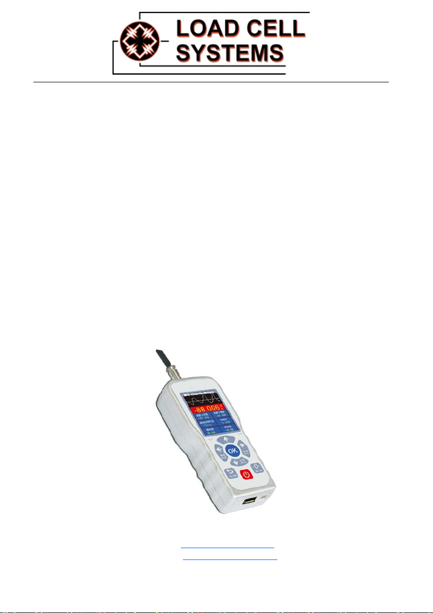
HANDHELD FORCE MEASURING INDICATOR
HHI
Contents
Specifications and Parameters……………………………………………… 2
Appearance and Dimensions ……………………………………………… 4
Test Benches
……………………………………………………………… 5
Precautions ………………………………………………………………… 6
Functions
Main Features
…………………………………………………………………… 7
……………………………………………………………… 7
Parts & Buttons and Their Functions ……………………………………… 8
Interfaces and Their Functions………………………………………………12
Test Description
……………………………………………………………19
Software …………………………………………………………………… 21
Main ten ance and Af te r-Sales Service ………………………………………26
Battery Use and Maintenance ………………………………………………27
Packing Li s t
…………………………………………………………………28
Load Cell Systems reserves the right to change specifications without notice. ©2018
Web: https://loadcellsys.com
Email: [email protected]
Phone: 607-426-1467
Page 2
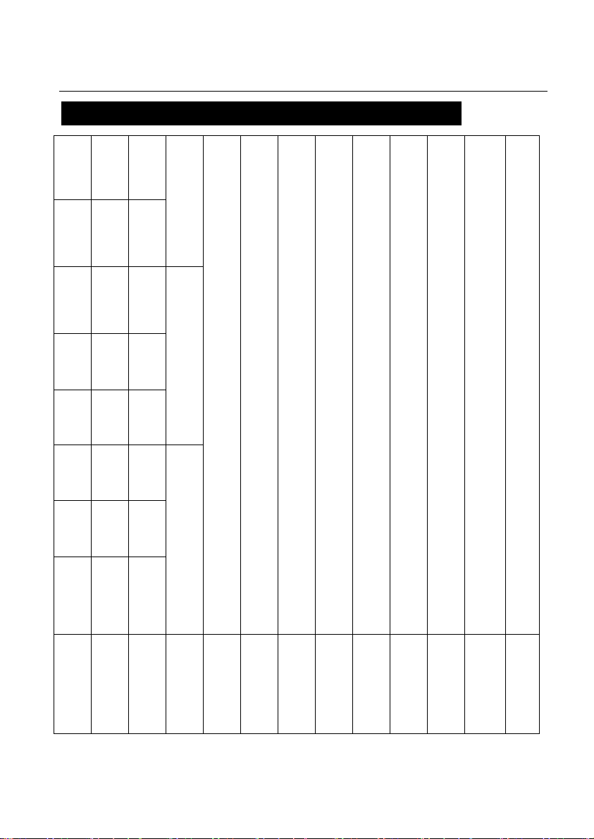
Specificati ons an d Parameters ( for Embedded Products)
alibration
Calibration
f P
ensor
E
Units
isplay
Tt
elative
H idit
Conditions
TX-500
500N
0.1N
1Mpa
TX-200
200N
0.1N
TX-100
100N
0.05N
TX-50
50N
0.1Mpa
0.01N
1kg
±0.5%F.S
TX-20
20N
0.01N
TX-10
10N
0.005N
1%~100%F.S
Embedded sensor
N、kg、lb
20±10℃
15%~80%RH
2.8-inch true color
No vibration sources or corrosive materials exist.
TX-5
5N
0.001N
0.01Mpa
TX-2
2N
0.001N
Model
Range
C
S
Measuring RIndication
- 2 -
D
Working
R
Working
Weight
Page 3
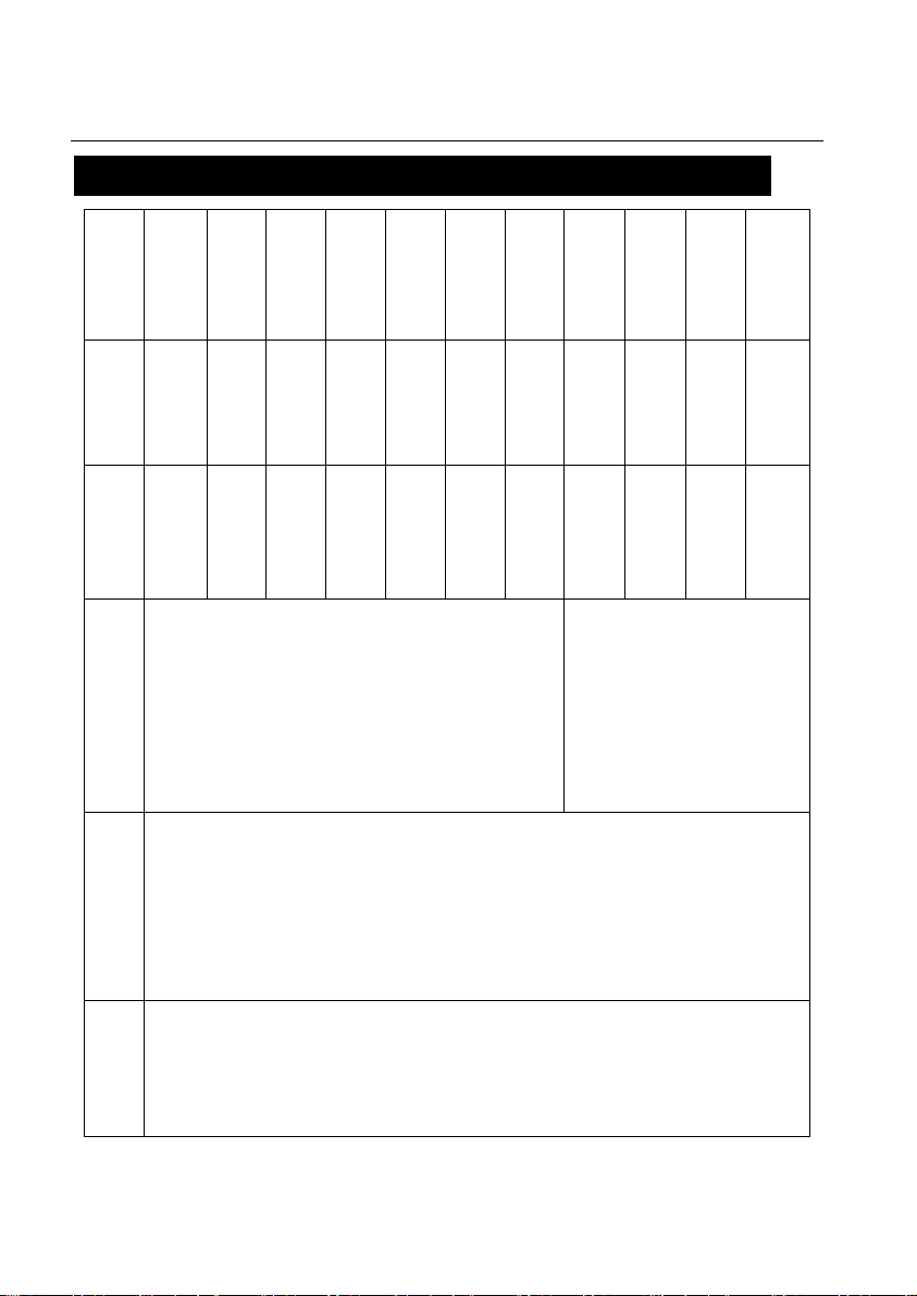
Specifications and Parameters (for External Products)
alibration
xternal S
Measuring
Range
Indication
Error
±1%F.S
sensor
Model
TX-1K
TX-2K
TX-5K
TX-10K
TX-20K
TX-50K
TX-100K
TX-200K
TX-500K
TX-1000K
10kN
20 kN
Range
1000 N
2000 N
5000 N
1 N
0.5 N
C
1 N
0.005kN
-shaped
50 kN
100 kN
200 kN
500 kN
1000 kN
0.1 kN
0.1 kN
0.01 kN
0.01 kN
0.05 kN
0.5 kN
TX-2000K
2000 kN
1 kN
Sense
sensor
E
1%~100%F.S
on the
(depending
- 3 -
configured)
sensor
External spoke
Page 4
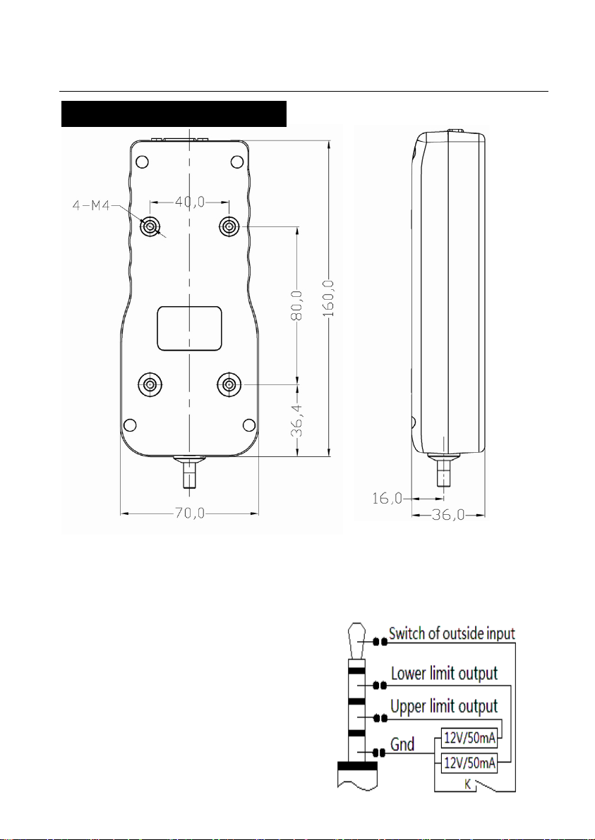
Appearance and Dimensions
mm
Output Port Wiring
- 4 -
Page 5
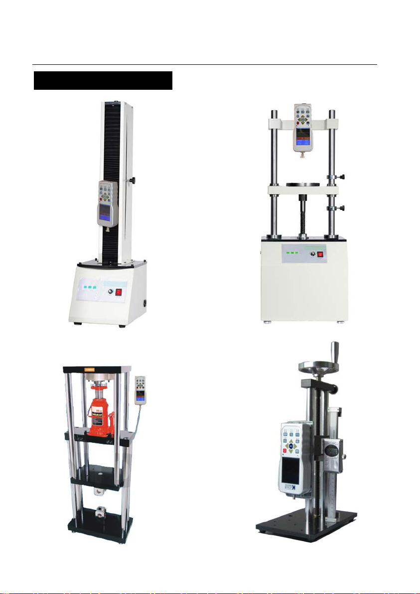
Test Benches (Optional)
- 5 -
Page 6
Precautions
Notes
Warning
Misoperation ma y cause damage to the force
gauge and even result in serious accidents.
This manual describes precautions against
accidents and operation methods of this
product. Make sure to read this manual carefully and safe keep it after the
rea din g. F or i mpact tes t, sel ect a f orce gauge whos e maxi mum measurable value
is doubled the impact load to be applied. Effective measuring range of this
product is 10% ~ 100%.
1
、 B efore the impact t est, wear mask a nd gloves; avoiding personal injury i n
case of object splash.
2、 Do not use damaged or bent fixture; avoiding personal injury in case of
fixture fall or break.
3、 I f “ Warnin g: te s t load ex ce eds mea s ur e ment ” a ppe ar s on the LCD display, it
indic at es t ha t th e te st l oa d the s ens or me as ure s is 110 % la rger tha n t he r a te d
load. Decr ease the l oad i mmedia tely. Ma ke sur e the l oa d appli ed is smal ler
than 105% the rated load after the force gauge is restarted.
4、 Make sure the force gauge is not overloaded. Overload, excessive impact
force, and forces other than pull force and push force may damage the
sensor.
5、 Do not use sharp tools to press buttons.
6、 Avoi d the forc e ga u ge fr om wa te r, oil , an d ot her liq ui ds. Put i t i n a co ol , dr y,
and vibration-free place.
7、 Use the charger delivered with the force gauge for charging; otherwise,
- 6 -
Page 7
circuit failure even fire may be caused.
8、 F ollo w this d ocu ment t o wire por ts; other wise, circ uit fa ilur e even P C faul t
may be caused.
9、 M ake sure the A C charger is se curely i nser ted int o a so cket if the pr oduct
nee ds to be cha rge d. Loos ene ss may ca use s hort cir cuit , r esult in g in el ect ri c
shock or fire.
10、Remove the power adapter after the charging; avoiding accidents.
11、Do not touc h t he power a dapter wi th wet hands; ot herwis e, electric sh ock
may occur.
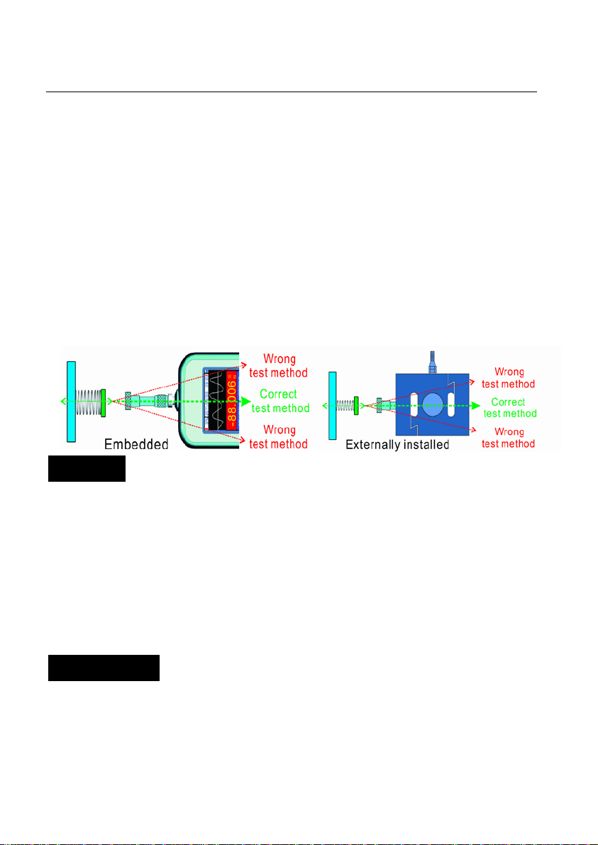
12、This product is for measuring pull and push forces only. Do not bend or
twist the test head. See the f o l l ow i n g f i gure f or corre ct op erat i on me tho d.
Functions
BIN-106 series digital f orce gau ges are ne w-genera tion uni versal portable
instruments for testing pull and push forces. They are characterized by
compa ct ness , li ghtne ss, port abi lit y, versa til it y, hig h prec isi on, a nd cur ve ca pt ure ,
applicable to pull & push test, insertion & extraction test, and impact test of
various products. Th ey can b e als o desig ned int o small -size d t est machines for
various purposes when they are combined with different test benches and
fixtures.
Main Features
1、 2.8-inch TFT true c olor displa y; both dire ction bu ttons a nd displa y can be
rotated 180°.
2、 Built-in real time clock;USB interface; hot swappable.
- 7 -
Page 8

3、 Pe ak va lue s, rea l-time values, and test curves can be displayed on the same
screen; enabling procedural monitor and reproduction of the test.
4、 Free setting of fracture alarm value, fracture alarm dead zone, and
upper/l ower offs et; s electi on o f fracture alarm, ala rm for not excess o f limit,
and alarm for excess of limit. When alarm values ar e exceeded, the buzz er
acts while the dis play s hows a lar m infor mati on. The two SC open-collector
level outputs drive the DC 12V relay or the solenoid to act, each output
being 50mA. To use output ports, connect the power adapter first.
5、 E nable a uto matic unit conv ersio n: N, kg, a nd lb ; pr essur e uni t MPa can be
converted as well.
6、 Peaks can be held or cleared; clearing time can be set.
7、 A maximum of 100 groups of test reports can be saved permanently. The
save d c ont ent i ncl ud es t est ti me, peak, an d a vera ge va lle y. One gr ou p of t e st
curves can be saved(Automatically cleared after shutdown) as well for
reproducing the test procedure.
8、 Material strength can be calculated based on sectional area input.
9、 Shutdown and backlight can be set to perform automatically.
10、Chine s e/E n glis h s wit c hov er ; pi ct ur es an d li ter a ry d esc ri pt io ns make va r ious
operations easy to understand and learn.
11、Relying on the PC dedicated test software, the force gauge can realize
unlimited storage, transmission, and reproduction of test curve data.
12、Inst alled on diff erent t est be nches, the f orce gau ge ca n imple ment va rious
tests.
- 8 -
Page 9
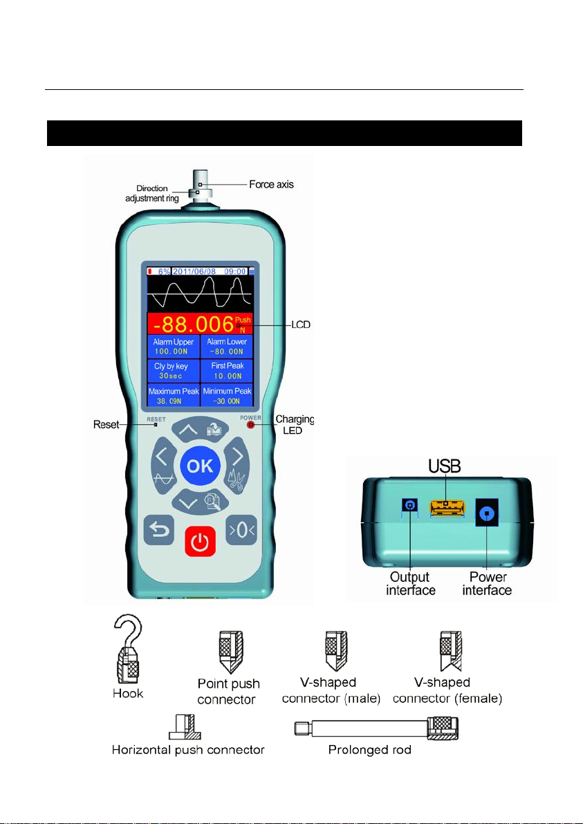
Parts & Buttons and Their Functions (for Embedded Products)
- 9 -
Page 10
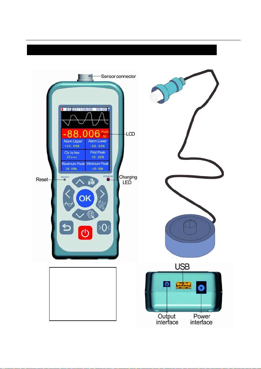
Parts & Buttons and Their Functions (for External Products)
iring methods of
——
+
;2——
-
;
——
+
;4——
-
;
——
W
the sensor:
1
3
5
V
S
P
V
S
- 10 -
Page 11
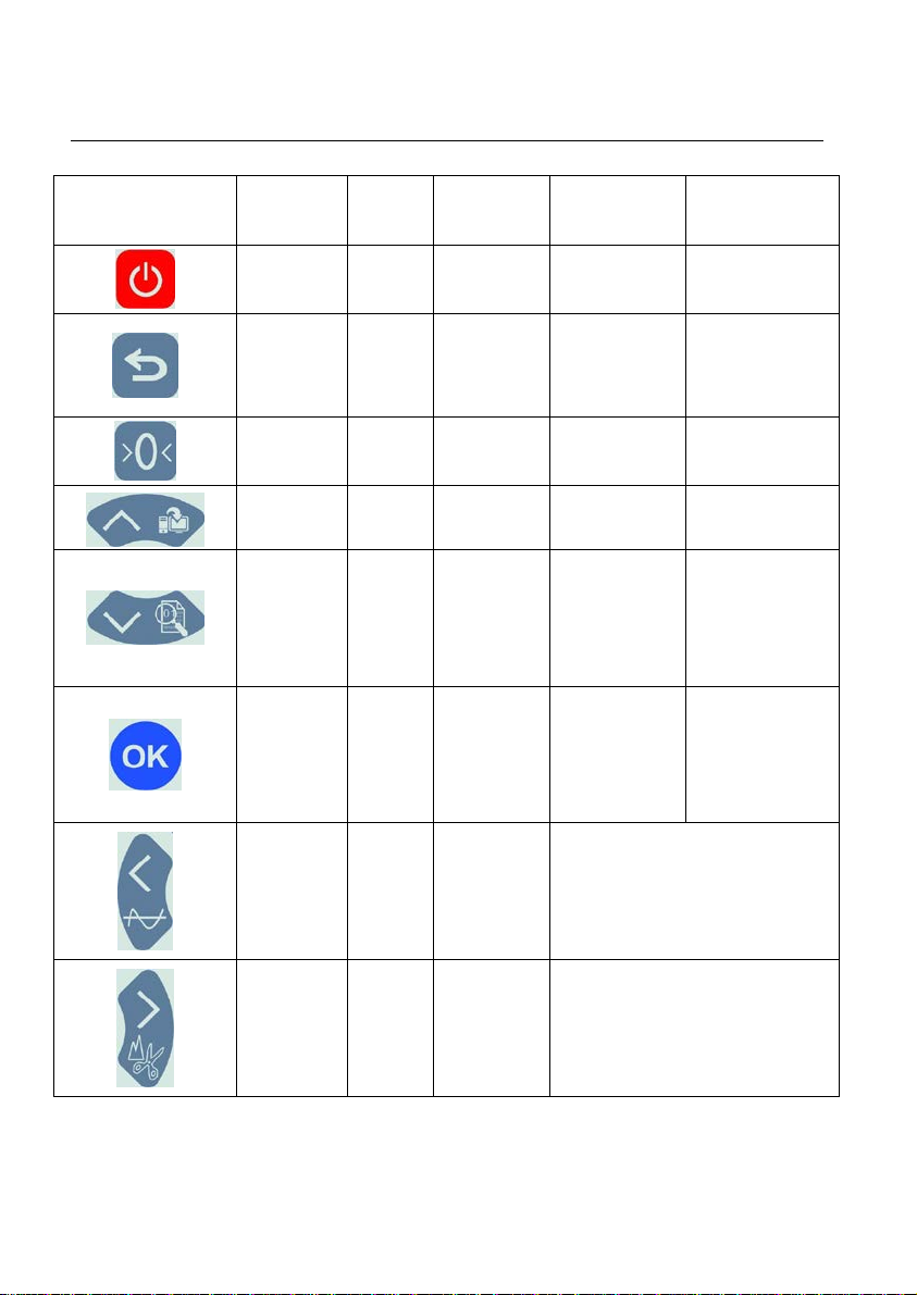
Buttons and Their Functions
output
Button
Standalone
Test Mode
Shutdown Invalid Shutdown Invalid Invalid
Capture
Mode
Online Test
Mode
Storage &
Query Mode
Menu O peration
Mode
Inv
alid
Zero set
Test
Ent
er
storage &
query
mode
Enter
parameter
setting
mode
Cur
ve
capture
start
Quit
capture
Invalid
Invalid Invalid
Invalid Invalid
Capture
stop
Invalid
Invalid Exit
Zero set
Invalid
Curve
capture
start
Quit parameter
modification or
exit
Invalid Invalid
Up Up
Switch to
upper
window
View report
and output
test value
Move the blinking number
leftward by one unit
Down
Confirm
parameter
modification
k
Pea
clearing
Invalid
- 11 -
Peak
clearing
Move the blinking number
rightwa rd by one unit
Page 12
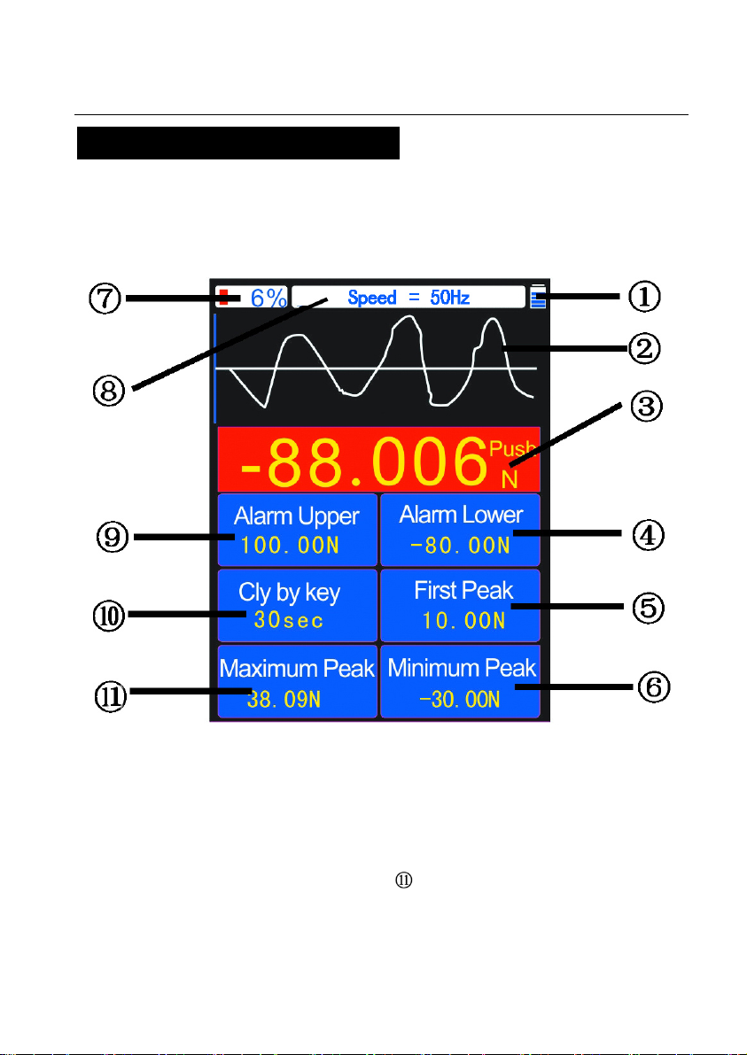
Interfaces and Their Functions
1、Test Interface:
Press and hold the "ON/OFF" button to start the force gauge. The following
interface appears.
①、Battery level
②、Curve
③、Real-ti me force
④、Lower limit alarm
⑤、First peak
⑥、Valley-to-peak
⑦、Number of reports saved
⑧、Sampling Speed
⑨、Upper limit alarm
⑩、Peak hold time
、Peak-to-peak
- 12 -
Page 13
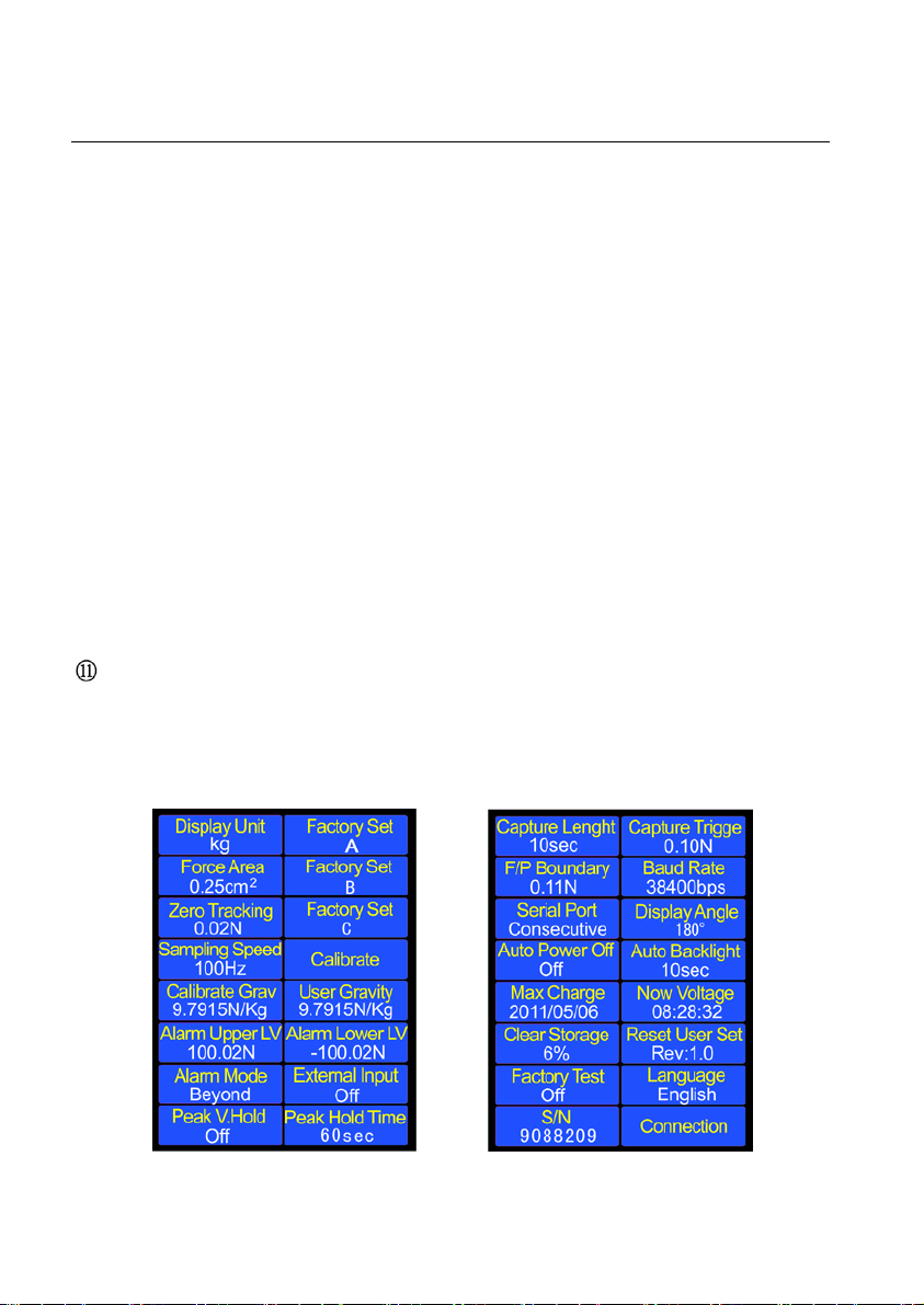
Test Functions
①、Battery level: real-ti me display. In cas e of p ower s horta ge, t his ic on bli nks
and an alarm is reported.
②、Curv e: force -to-time curve.
③、Force: rea l-time display. A ma ximu m of 5 digi ts can b e show n. Its unit ca n
be converted on the setting interface.
④、Lower limit alarm: values can be specified on the setting interface.
⑤、First peak: the first peak value after the test starts.
⑥、Valley-to-peak: the minimum force that is smaller than the initial value.
⑦、Number of reports saved: a maximum of 100 groups of reports can be saved
and the latest group of test curves can be saved as well.
⑧、Display sampling speed.
⑨、Upper limit alarm: values can be specified on the setting interface.
⑩、Peak hold time: this parameter can be set on the setting interface and
manually cleared.
、Peak-to-peak: t he max imu m p os itiv e pe a k.
2
、Interface Setting
On the test interface, press "OK" to enter the setting interface. The setting
interface falls into 2 pages.
- 13 -
Page 14

【Display Unit】
When t he ma in u ni t i s s et t o "g", available values of [ Display U nit] in clude:
"g", "mlb", "mN", and "Pa".
When t he main u ni t i s s et t o "kg", availa ble values of [Display U nit] i nclude :
"kg", "lb", "N", and "KPa".
When th e mai n unit is set t o "t", available values of [Display U nit] include:
"t", "klb", "kN", and "MPa".
【Force Area】
When [Display Unit] is set to "Pa", "KPa", or "MPa", [Force Area] will
involve in calculation.
Note: Pressure test result will be accurate only when [Force Area] is set.
【Zero Tracking】
Availa ble values include "shutdown", "1d", "2d", "3d", "4d", and "5d".
Befor e the z ero point become s stab le, val ues smal ler tha n [Zer o Tr acki ng]
are automatically clea red. After the test values become s table, test freque ncy is
once per s ec on d. Varia nts o f th e t est val ues t hat a re s mall er tha n [Zero Tracking ]
are automatically cleared, to hold the displayed values.
【Sampling Speed】
When it is set to "6Hz ~ 1600Hz", it indicates force s ampling speed per
second.
Note: The hi gher the sampli ng speed, the lo wer the t est accuracy. Higher
sampl ing s pe ed a ppli es t o dynamic a nd tr ans ient tes t; a nd l ower sa mpli ng sp ee d
applies to static and slow test.
【Calibrate Grav】The G ravi ty of ca l ib rat i on place a d ding s peed
【User Gravity】The Gravity of Using place adding the speed
Its value is "9.600 ~ 9.900" N/Kg.
This parameter is used for gravity correction. The displayed value = test
value + test value * ([Calibrate Grav] – [User Gravity]).
【Alarm Upper LV】For setting alarm upper limit value.
【Alarm Lower LV】For setting alarm lower limit value.
- 14 -
Page 15
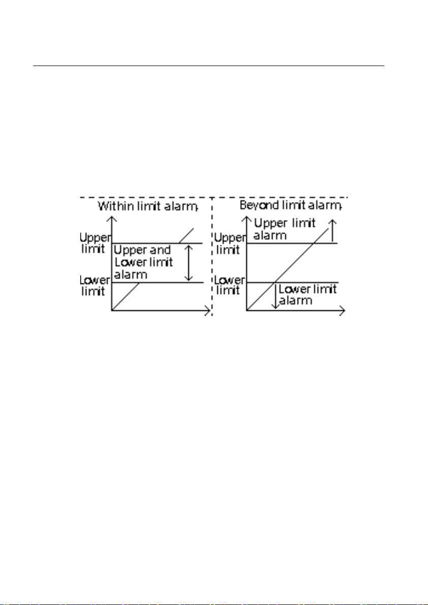
【Alarm mode】
Val ue s of t his pa r a mete r i ncl u de "Within", "Beyond", "Fracture", and "Shut
Off"; they are indicative of within limit alar m, beyond limit alarm, fracture alarm,
and shutoff alarm.
If the value is set to "Within" or "Beyond", when the alarm value is
exce e d e d, the b uzze r a c t s whi le the di splay s ho ws a l arm infor matio n. Meanwhile,
the Boolean value is output. The following figure shows differences between
within limit alarm and beyond limit alarm.
If
the value is set to "Fracture", [Alarm Upper LV] and [Alarm Lower LV]
will be automatically switched to [Fracture Alarm] and [Fracture Dead]. Set
these two parameters. Whe n the f orce va riation is reduced to the set value, the
buzzer a cts while t he display shows alarm infor mation. Meanwhile, the upper
Boolean value is output.
Note: To use output ports, connect the power adapter first. The two SC
open-collector le vel out put s dr ive t he D C 12 V rela y or the s ol en oid t o act , ea ch
output being 50mA.
【Peak V. Hold】a switch for enabling peak hold function
Its va l ues i n c l u de "on" and "off".
If this parameter is set to "off", t he pe ak va lue will not b e dis pla yed o n th e
interface.
【External Input】external switch for enabling capture
Its va l ues i n c l u de "on" and "off".
- 15 -
Page 16

When thi s pa r a mete r i s s et t o "on", ena bli ng t he ex ter na l swit c h (eq ui va le nt
to the "curve c apt ure " butt on or the "c urve c apt ure" i nstr uct ion) to be tur ned on ,
the force gauge will enter curve capture mode. Note: capture time length is
subject t o t he sa mp li n g spe ed. Ca pt ur e ti me ( u nit : s ec on d) = numb er of ca ptur e d
data / sampling speed
【Peak Hold Time】
Its va l ues i n c l u de "Clr by Key" and "1 ~ 60 sec".
When t his par ameter is set to "Clr b y Key", t he peak r emains uncha nged
until users press the "Peak Clearing" button or "Zero Set" button. When this
parameter is s et t o "1 ~ 60 sec", t he peak will be a uto matically re-measured after
the set time is up. The pe ak can a lso be r e-meas ured by manual ly press ing t he
"Peak Clearing" but t o n or "Zero Set" button.
【Capture Lenght】
Set range: 1 ~ 1280 seconds
This parameter indicates the curve capture time in capture mode. The
capture time depends on the sampling speed: 60Hz: 1 ~ 1280sec; 12Hz: 1 ~
640sec; 25Hz: 1 ~ 320sec; 50Hz: 1 ~ 160sec; 100Hz: 1 ~ 80sec; 200Hz: 1 ~
40sec; 400Hz: 1 ~ 20sec; 800Hz: 1 ~ 10sec; 1600Hz: 1 ~ 5sec.
【Capture Trigge】
Set range: –99999 ~ +99999
The [F/P Bo undary] parameter serves as a co ndition of triggeri ng captur e
after the force gauge enters the curve capture mode. If the number of data
capt ured reac hes utmos t or ca pt ure is s t o p pe d i n a d vance , a c a pt ur e r ep ort wi ll b e
generat ed and sa ved. The cur ve will be clear ed a fter the force gauge exi ts the
capture mode.
【F/P Bounbary】first peak boundary
Set range: 1 ~ 99999
This pa ra meter is use d for deter mi nin g fir st pea k dur ing pe ak te st. Ta ke th e
ass umption t hat the criter ia for det ermini ng a peak is 10. After users press the
"Peak Re-measuring" button, a new peak test is started. During the test,
- 16 -
Page 17

peak-to-peak (Vmax), valley-to-pe ak (V min) , an d ne w pea k ( Vne w) a re up dat ed
continuously. If the absolute value of (Vmax – Vnew) or (Vmin – Vnew) is
larger than 10, Vmax or Vmin is considered the first peak.
【Buad Rate】serial port baud rate
Set range: 4800 ~ 230400bps
Format: 1 initial bit; 8 data bits; 1 stop bit. No parity bit. This parameter will
take effect after users restart the force gauge.
Note: In order to ensure t hat eac h data is sa mpled dur ing communi cation
wit h a P C, b aud rate is rec ommende d to set as foll ows: 6Hz: ≥ 4800bps; 12Hz: ≥
9600bps; 25Hz: ≥ 14400bps; 50Hz: ≥ 19200bps; 100Hz: ≥ 28800bps; 200Hz: ≥
38400bps; 400Hz: ≥ 57600bps; 800Hz: ≥ 115200bps; 1600Hz: ≥ 230400bps.
Due to speed limits of serial ports, if the sampling speed is larger than 400Hz,
data will be lost when it is transmitted to a PC. Instrument reading results prevail.
【Serial Port】serial port output way
This parameter is used for controlling real-time data transmission.
Parameter values and meanings are as follows:
Prohibit: The serial port is forbidden to transmit real-time data.
Key/Order: When the
button is pressed or an output command is
rece ive d, o utp ut is per for med once . If the for ce gaug e is con nect ed t o a P C, P C
progr ams wi ll a u to mati c a l l y f or b i d t he o utput f un c tion.
Change: When test data cha n ge s , o ut p ut is performe d o nc e.
Stabilize: When test data becomes stable, output is performed once.
Consecutive: Test data is transmitted uninterruptedly.
【Display Angle】
This paramet er is use d for chan ging dis play a ngle. Available values are 0°
and 180°.
【Auto Power Off】
This is an energy-saving design. When the force gauge is idled for a
specified period, it will automatically shut down.
- 17 -
Page 18

【Auto Backlight】
This is an energy-saving design. When the force gauge is idled for a
specified period, it will automatically adjust backlight brightness.
【Clear Storage】clearing stored data
This parameter is used for clearing stored test reports and curves. When
stor ed dat a is overflowed, the system will a utomatically clear all data a nd begin
stor ing new c a ptured dat a .
【Reset Us er Set】reset parameters
this pa ra met er is us ed f or re st or ing fa ct or y s ett in gs i n ca se o f wro ng s et ti n g
or other setting problems.
【Language】Chinese/English switchover
【Factory Set A\B\C】【Factory adjustment and self-test】
This pa ra meter is use d onl y duri ng fa ctor y sett in g. User s ar e not a ut hor iz ed
to set this parameter.
【Connection】
This par a meter is pr o vide d to us e rs for c onn ect or wi ri ng. User s can refer to
it during connector wiring.
【S/N】local sequence number
This parameter indicates internal sequence number of the machine. Users
are not authorized to set this parameter.
3
、Calibrate:
①Press "↑", "↓", "←", or "→" to move t he curs or to [Calibrate] and pres s
"OK" for confirmation. Then, press any button to enter the calibrati
i
nterface, as shown in figure a.
②Press "↑", "↓", "←", or "→" to move the cursor to [Inp ut Weight] a
ress "OK" f or co nfi rma t i on. Press "↑" or "↓" t o chan g e "NO" to "YES" a
p
on
nd
nd
press "OK" for confirmation.
③Press "↑", "↓", "←", or "→" to move t he c ursor to [CAL Point] a nd pre ss
"OK" for confirmation. Press "↑" or "↓" to set the number of a calibra tion
point to a desire d value a nd press "OK" for confirmation. (The maximum
- 18 -
Page 19
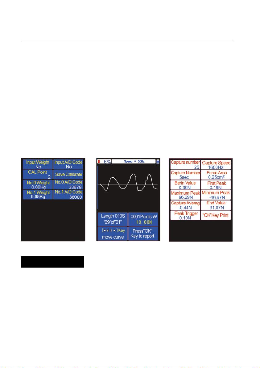
valu e of the calibration point is 6.)
figure a
figure b
figure c
④Press "↑", "↓", "←", "→", or "OK" to chang e values of other calibra tion
points and press "OK" for confirmation.
⑤Press "↑", "↓", "←", or "→" t o move t he c ur sor t o [No.0 A/D Code]. After
the inter nal code bec omes stable, press "OK" for confir mati on. The c ursor
automatically moves to [No.1 A/D Code] and the system loads weight that is
equivalent to one calibration point. After it bec o mes sta b le, press "OK". The
cursor moves on to the next calibration point….After the last calibration
point is confirmed, the cursor moves on to [Save Calibrate]. Press "OK"
and then press "Back" to exit.
4
、Figures b and c show report content
(a maximum of 100 groups of reports and 1 group of curves can be saved).
Test Description
After understanding interfaces and functions, you are expected to start test:
1、 Insta ll a head for test. Choose a proper h ea d ac ces s or y or fix tur e f or tes t a nd
install it onto a rod. Note that d o not scr ew the head wi th exces sive f orce;
otherwise, the sensor may be damaged.
2、 Connect the sensor to the force gauge and install a fixture. Use a wire to
connect the sensor connector with the force gauge in a proper manner.
- 19 -
Page 20

Choose a pro per f ix tur e a n d inst a l l in ont o the sens or. Note that do not s cr e w
the se ns or with e xce s si ve f orc e; ot h er wise , t he se ns or may be dama ge d. This
step i s ap pl i ca b l e to e x t ernal for ce ga u ges .
3、 Power-on. Press an d hold the "ON/OFF" button for 2 seconds to power on
the force gauge. The test interface appears. Check the battery level in the
righ t upper corn er of t he inte rfa ce. If battery level is low, connect the force
gauge to t he del iver ed p ower a dapt er f or char ging. The for ce gauge ca n be
charged in both startup mode and shutdown mode. During charging, the
force gauge ca n be tested as well. Wh e n the force ga u ge i s f u l l y char ge d, the
system will display a prompt. Remove the power adapter immediately.
4、 Set parameters. On the test interface, press "OK" to enter the setting interface.
Set such parameters as unit, force area, zero track, sampling speed, fracture
alarm, upper limit alarm, lower limit alarm, peak hold, capture trigger, and
capture length. After the setting, press "Back" to go back to the test interface.
5、 Test. Install the sensor onto a proper bench for test. Press the "Zero Set"
button and the "Peak Clearing" button. Two test methods are available: one is
direct test. In this cas e, real-time for ces, peaks, and other parameter values
are obta ined which wil l not be sa ved. These val ues will b e cleared once a
new test is performed. The other method is curve capture. On the test
interfa ce, press the "C urve Ca pture" b utton t o enter the ca pture mode. The
system will automatically start test when the capture trigger condition is met.
If users press "OK" or the captur e time is up, the test is completed. Peaks,
curves and other parameter values will be obtained.
6、 Report query. Test perf ormed i n capt ure mode wi ll be s ave d, incl udi ng tes t
cur ves and t est res ults. Only 1 group of curv es can b e save d and it can be
queried b y pressi ng the "Query" button. If users restart the force gauge or
perform a new t es t, the curves will b e clea r e d. A maximum of 100 groups of
reports can be saved and they can be queried by pressing the "Query" button.
7、 Shutdown. Press the "Back" b utt on t o go b ac k to t he t es t int er face and the n
press the "ON/OFF" but ton to s hut dow n the forc e gauge. The "ON/OFF"
- 20 -
Page 21
button is effective on the test inter fa ce onl y. Remove the sensor and clean the
force gauge. Ma ke sure to put t he for ce ga uge bac k into it s box for fut ure
use.
Software
Whil e connec ted to a seria l port of a PC over t he dedic ated USB line, the
force gauge can make use of the dedicated s oftware to realize unlimited storage,
transmission, and reproduction of test curve data.
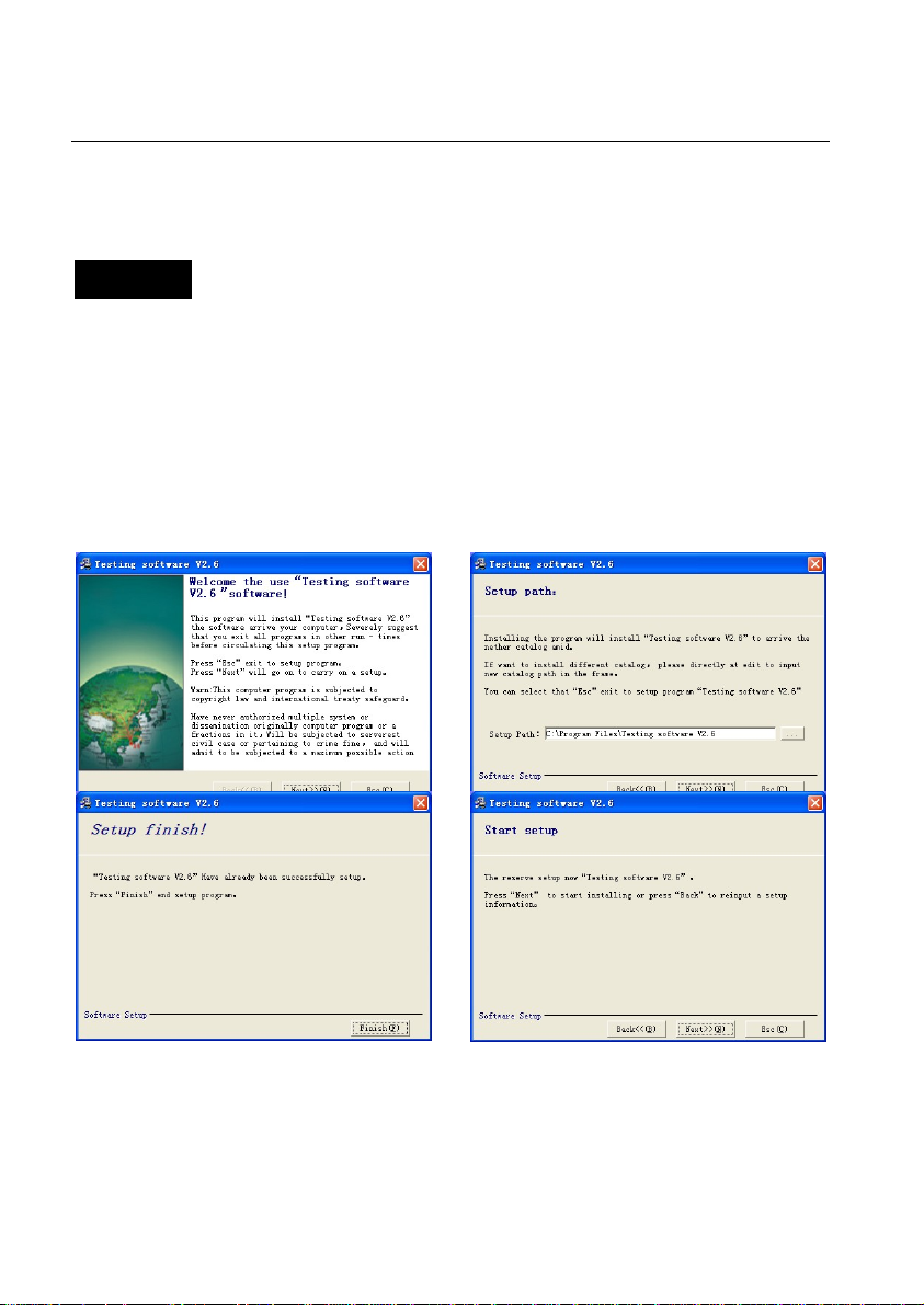
1、 Installing software:
Put t he dis k de li ver e d wit h t he for ce ga uge run i nto the PC dri ver and s ea rc h
for the "force gauge test software_setup.exe" file. Double-click the file and
follow the steps below to complete installation.
2
、 Interface functions:
After th e installation, click the softwa re icon to start it. Whe n yo u firs t sta rt
the software, the absence of any historical test data, so a lot of the content is
- 21 -
Page 22
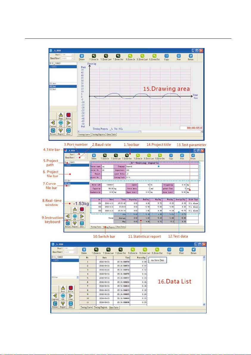
blank, The following interface appears.
- 22 -
Page 23

……1. Toolbar: shows various buttons of the software in differ ent modes. Users
can click them to perform corresponding operation.
……2. Baud rate: it should be set consistent with the baud rate of the force gauge
so that the force gauge can communicate with the PC.
……3. Port number: it sh ould b e set to the nu mber of t he por t over w hich t he
forc e gauge communicates with the PC.
……4. Ti tl e ba r : sh o ws t he name of c ur rent pr oject o pe n ed.
……5. Project path: indicates the path of the current project opened.
……6. Project file bar: lists all other proje cts t hat ar e stor ed in t he sa me pa th as
the c ur re nt proje ct o pe ne d. Us ers ca n clic k "Delete" or pr es s t he "Delete" button
through a keyboard to delete selected files.
……7. Curve file bar: lists all curve files of the current project opened. Users can
click "Delete" or pre ss th e "Delete" but t on t hr ou gh a ke yb oar d t o de le te s el e cte d
files.
……8. Real-ti me windo w: s hows t es t da ta in r ea l ti me mode if t he f orce ga uge i s
successfully connected to the PC.
……9. Inst ruct ion ke yb oard: in non-ca pt ure mo de, use rs c an us e t he "Instruction
keyboard" t o op erat e the for ce gauge i f the force ga u ge i s s ucces sful l y con ne c t ed
to the PC.
……10. Switch bar : allows users to swit ch betwe en "Test Cur ve" "Statistical
Report" and “Data sheets”.
……11. Statistical report: shows statistical values of the project under test.
……12. Test data: shows data of various curves of the project under test.
……13. Test parameter: shows parameters for the project under test.
……14. Project title: shows information of the project under test.
……15. Drawing area: draws real-time or historic curves.
……16. Datasheets: di splay t he force value at the time get from historical test
project and export data
3
、 Online test
1) Use the US B l i n e deli vered w ith t he pro d uct to con n e ct the force ga u g e
- 23 -
Page 24
to a PC. To avoid damage to the communication port, make sure the
forc e gauge is p o we r e d of f.
2) Select the number of a communication port for the force gauge and the
PC.
3) Select the baud rate that is consistent with that of the force gauge.
4) Press "Online" to connect the force gauge and the PC.
5) If online connection fails, follow prompts for check.
6) If the system prompts baud rate change, follow the pr ompt t o change
"Sa mpli ng Speed" or "Baud Rate" and restart the force gauge. Reset
the baud rate again after the force gauge is restarted.
4
、 Creating a project
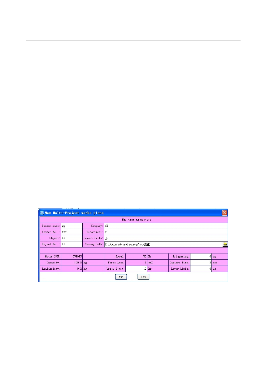
1) If online connection is successful, click "Create". The "New Test
Project" sheet is shown.
2) Enter related information. Note that only white cells are editable.
3) Click "OK".
4) If the system prompts information, follow the prompt to change the
input and click "OK" again.
5
、 Capturing a curve
1) Click "Capture".
2) Ca pt ur e pro mp t is di spla y ed.
3) Confirm the prompt to enter the "Curve Capture" interface. Capture
will be triggered after related conditions are met.
- 24 -
Page 25

4) The system starts curve capture and countdown after capture is
triggered. Whe n t he ti mer ex pir es, c apt ure is a uto mati cal ly c ompl ete d.
Curve files will be saved and statistical reports will be updated.
5) Dur ing capture, if users click "Re-capture", the captur ed data wi ll be
cleared; if users click "Cancel", the c a pture o perat i o n wi ll b e ca nc el ed.
6
、 Opening a project
1) To open a proje ct, us ers c an cli ck "Open" or double-clic k a proj ect i n
the "Project File Bar".
2) The pr oj ect o pene d is co nsi dere d the curr ent pr oje ct a nd al l new cur ve
files belong to the current project. Statistical reports contain
information of the current project.
7
、 Opening a curve file
1) If a pr oj ec t is o pe ne d, a ll c ur ve f il es o f t he proj e ct wil l b e lis t ed i n t h e
"Curve File Bar".
2) Double-click a curve file in the "Curve File Bar" to open the curve.
3) For a c ur v e t hat is s uc c es sful ly op en ed, c urve di a gra m will b e dr awn i n
the "Drawing Area".
4) Within the drawi ng area, users can left-click to draw up a part of th
c
urve ; rig ht-click to display all curves; fli p the mouse wheel to z oo
n/out the c ur v e ; a n d mo v e t h e c ur sor o nto th e curv e to read val u es o f a
i
point.
5) Click "Back" t o e x it c ur v e o pe r atio n.
8
、 Deleting a project
1) If the "Project File Bar" is available, users can click "Delete" or pr ess
the "Delete" button through a keyboard to delete selected files.
2) This operation will delete the project and all its curve files.
9
、 Deleting a curve
1) If the "C urve File Bar " is avail able, users can clic k "Delete" or press
the "Delete" button through a keyboard to delete selected files.
2) This operation will delet e the selec ted file. Meanwhile, correspondin
- 25 -
e
m
g
Page 26

statistical reports will be updated.
、Printing a curve
10
1) Open a project.
2) Click "Test Curve" in the "Switch Bar".
3) Double-click a desired curve file in the "Curve File Bar".
4) Click "Print" t o print t he curve displayed in drawing area.
11
、Printing a statistical report
1) Open a project.
2) Click "Statistical Report" in the "Switch Bar".
3) Click "Print" to print the Statistical Report of the project.
12
、Export data
Click “export data” can export the force value at the time get from
historical test project and save a “*.xls” file.
Maintenance and After-Sales Service
1、 Use soft dry cloth for cleaning the product. The cloth must be wetted in
clea ner wate r a nd dri ed fir st b ef ore r ubb ing o ff dus ts a nd s tai ns. Do n ot us e
volatile chemicals, for example, volatile oils, diluents, and alcohols.
2、 M ake sur e t o c on t r ol f orce d ur i n g us i n g or movi n g of th e pr o d uct.
3、 Do not disassemble, repair, or change the product by yourself.
4、 In case of a fault, contact the local shop or the manufacturer.
5、 Upon th e warr anty date , provi ded tha t the prod uct is un der nor mal use an d
has n o dama ge, if i t is f ound q ualit y prob lems withi n one month, user s can
go for the local shop or the manufacturer for replacement of the same
spec if ica ti on s a ga inst t he or i gi na l in voi ce , wa r ra nt y, and i nta ct pa cka ge. The
warranty period and clauses of the replacement inherit the original product.
6、 Upon the purchase date, provided that the product is under normal use, if it is
found a non-man-made fault (faults that are caused because users
disa ssemb le the pr oduct or have t he pro duct ma inta ined b y a third pa rty ar e
excl u ded fr o m t he wa rra nt y rang e) wit h in o ne y ear, users can go f or t he loca l
- 26 -
Page 27

shop for free maintenance against the original invoice and warranty.
Warranty period of batteries is 3 months.
7、 The warranty claus es of this pr oduct only appl y to products that are sold
wit hin Chi na. If your pr oduct has exce eded the produc t repla cement period
even the warranty period, contact the local shop or the manufacturer for
maintenance service. Maintenance service will be offered at users’ expense.
Battery Use and Maintenance
This produ ct i s confi gur ed w it h a 1600mAh 6V Ni-Hi rechargeable battery
group . If it is full y charged, the product can be r unning uninterruptedly for 10
hours. While being shut down, the battery group enables t he product last for 3
months. During use of t hi s pr oduc t, pa y a tt ent i on t o t he bat ter y le ve l at t he r igh t
upper corner of the screen. In case of power shortage, use the delivered
DC12V/1000mA power adapter to charge the product. It will be fully charged
within 8 ~ 10 hours. Remove the power adapter immediately after the
product prompts full charge. Otherwise, longtime charging may cause the
battery group to overheat, burning circuits or resulting in accidents.
Precautions:
1、 Recharging is recommende d only a fter the ba tteries a re completel y use d up.
This helps eliminate battery memory.
2、 Frequent charging or longtime charging will shorten service life of the
batteries.
3、 The pr oduct ca n be use d for tes t in c harge mode . Long-term no t work need
charging regularly (to avoid battery invalid)
4、 In normal cases, the batteries can be charged 500 times.
5、 Battery warranty period: 3 months.
- 27 -
Page 28
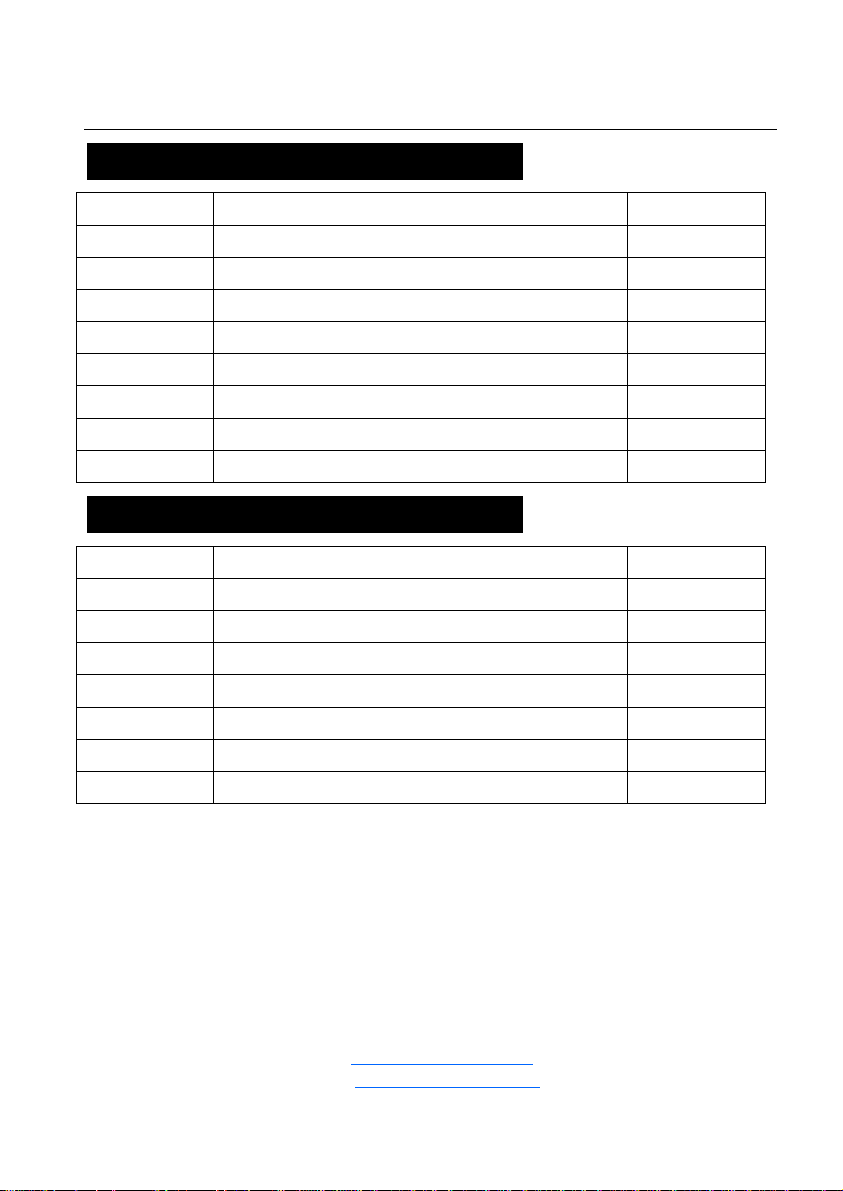
Packing List (for Embedded Products)
7
USB line
1
1
Force gauge
1
2
Power adapter
1
3
Sensor connector
1
No. Name Qty.
1 Force gauge 1
2 Power adapter 1
3 Head accessory 5
4 Prolonged rod 1
5 Warranty 1
6 Use gui de 1
8 Software setup disk 1
Packing List (for External Products)
No. Name Qty.
4 Warranty 1
5 Use gui de 1
6 USB line 1
7 Software setup disk 1
Load Cell Systems reserves the right to change specifications without notice. ©2018
Web: https://loadcellsys.com
Email: [email protected]
Phone: 607-426-1467
 Loading...