

Page 1
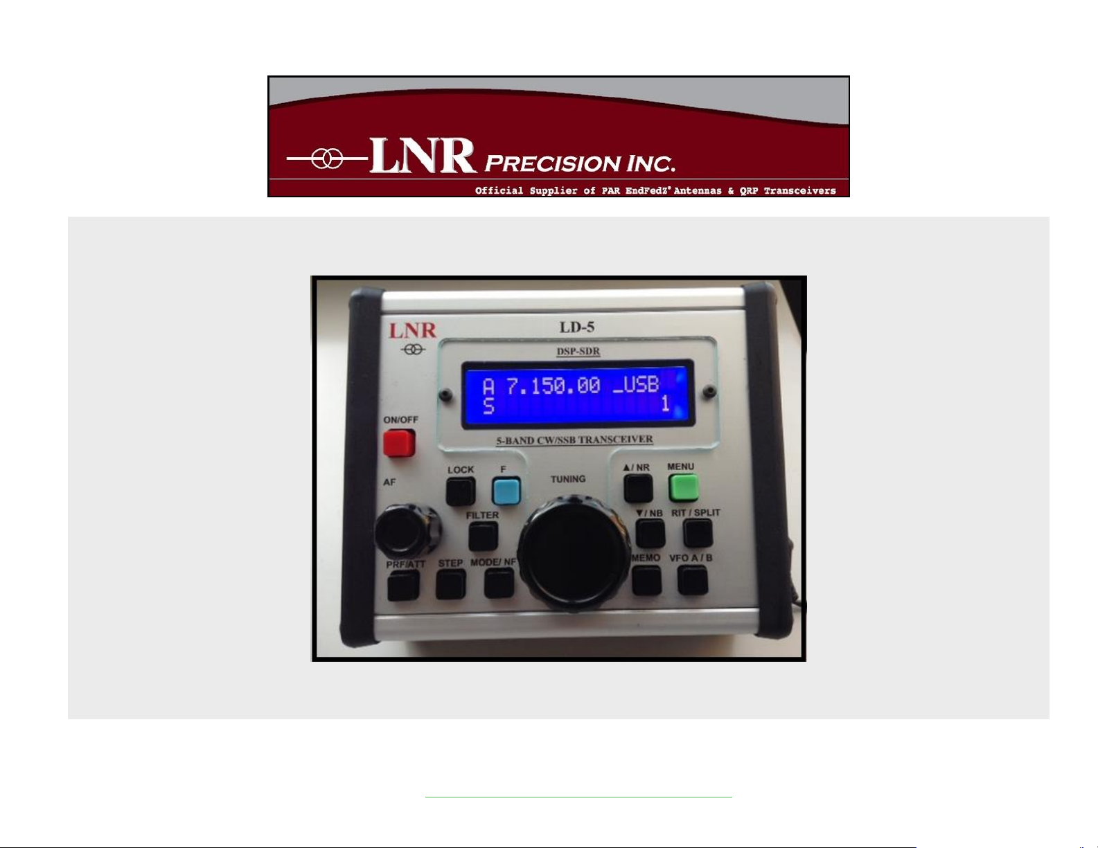
LD5 – CW/SSB QRP Transceiver
SDR /DSP
© 2014 LNR Precision Par EndFedz Antennas and QRP Transceivers
Page 2

Quick guide manual
Description:
At the development base of the digital signal processing unit, an algorithm is embedded for IQ processing of
the channels with phase suppression of the unwanted side-band channel.
Unit CPU \ DSP performs the following functions:
-------------------------------------------------- ------------------------------ Digital signal processing
Frequency synthesizer
Full control of the transceiver with direct conversion / SDR /
Applicaton:
Due to its small dimensions and light weight this transceiver is suitable for any portable or stationary
operation.
This unit contains:
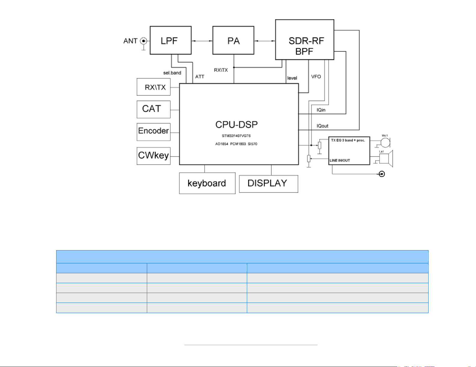
-CPU STM32F407,
-NS -24 bit ADC PCM1803,
-NS -16 bit DAC CS4338 low hissing amp
-HF-generator Si570
-1602-line LCD
-Matrix of buttons
-Encoder
The unit has electronic CW Iambic key, SWR meter and output power wattmeter.
Functions that this unit performs are separate and switchable for reception / transmission.
They are displayed on the screen display as RX / TX with symbols.
The LD5 is capable of firmware update via USB port. See LNR web page for instructions.
How to order:
LNR Website www.LNRprecision.com
Features
Emmision Modes: SSB, CW , DIGITAL
5W output power typ.
Very low noise floor due to DDC input stage
The unit has an electronic CW Iambic A/B keyer,
SWR meter and output power wattmeter.
High stability Si 570 generator
Split-frequency operation
PTT can be switched by connecting PTT to ground
RX/TX switching:
o push PTT input to ground
o AF VOX
Output SWR indicator
Optimal output power indicator
Integrated Sequencer
TX 3 band EQ – presets for bass, middle and treble
boost
© 2014 LNR Precision Par EndFedz Antennas and QRP Transceivers
Page 3
Specifications
General
Frequency range
7000 kHz – 22 MHz
40, 30, 20, 17 and 15 meter operation
Modes
USB, LSB, CW, CW-R, DIGITAL
DATA:CAT –USB jack : CW, PSK, RTTY, SSTV – 3.5mm jack
Power
5W output in CW / SSB
Frequency Stability
+/- 3 ppm (Si570 defined) typical
Block diagram
© 2014 LNR Precision Par EndFedz Antennas and QRP Transceivers
Page 4
© 2014 LNR Precision Par EndFedz Antennas and QRP Transceivers
over 0-50 deg C
Supply Voltage
10.5V min to 15V max
350Ma receive and 1.5 to 2 A typical in transmit
Push button operation
LO temp. Stability +/- 2.5
Antenna
50 ohms
BNC
Dual VFO
Memory
100 memory storage per band
Memorize frequency, mode, VFO’s
Built-in speaker
0.2 watts
Dimensions
4.724” long X 3.937” wide x 1.957 “ tall
Weight
19.0oz / 0,54kilogram /excluding microphone/
Iambic key
mode A and mode B
Pitch CW
Controls CW offset. The sidetone pitch is automatically set to equal the offset
Notch Filter
Automatic Heterodyne filter for SSB from -6 to -40 db
Noise reduction
level of attenuation of the noise from 1 to 50- use minimal necessary
Noise Blanker
adjusted in the range from value 4 to 12 readings depending on interference
CW VOX
Break in delay in CW – adjustable from 0.1 seconds to 5 seconds
CW memory keyer
Choose Iambic Mode A or B
VOICE VOX
VOX Delay adjustable from 0.1 seconds to 5 seconds
SSB VOX LEVEL
VOX GAIN 10-100 10 IS MOST SENSITIVE
Filters
8 different filters – 4 of 4 for CW/ SSB - 1-3 factory presets – No.4 adjustable for CW/50-
1000Hz/ and SSB/250-3.6KHz
Compressor SSB
0-20dB
SSB TX MUTE
Enable= no monitor Disable= monitor
Transmitter
Input Power
10.5-13.8 VDC
Output Power
3.5 – 8W
Page 5
Measurement
SWR and Power in numbers or bar
supply voltage –real voltage on
display
Two modes CW
Select a hand key or a paddle
Receiver
Receive sensitivity
0.2uV
Preamp
Ant Preamp
+12
dB
Spurious response rejection
IMD3 -48Db/ 5W
IMD5 -43dB
ATT
-6 db
© 2014 LNR Precision Par EndFedz Antennas and QRP Transceivers
Page 6
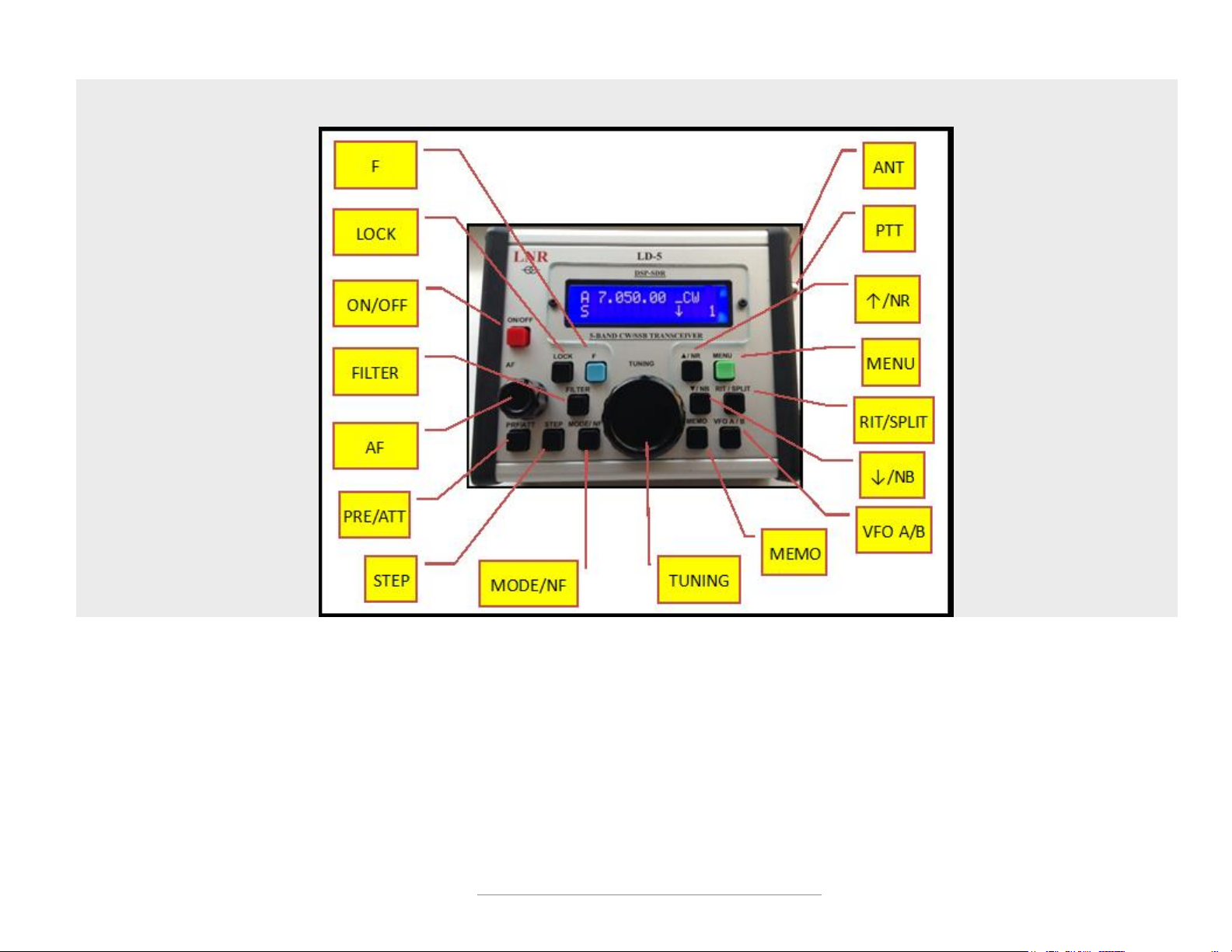
Front panel indicators and functions
© 2014 LNR Precision Par EndFedz Antennas and QRP Transceivers
Page 7
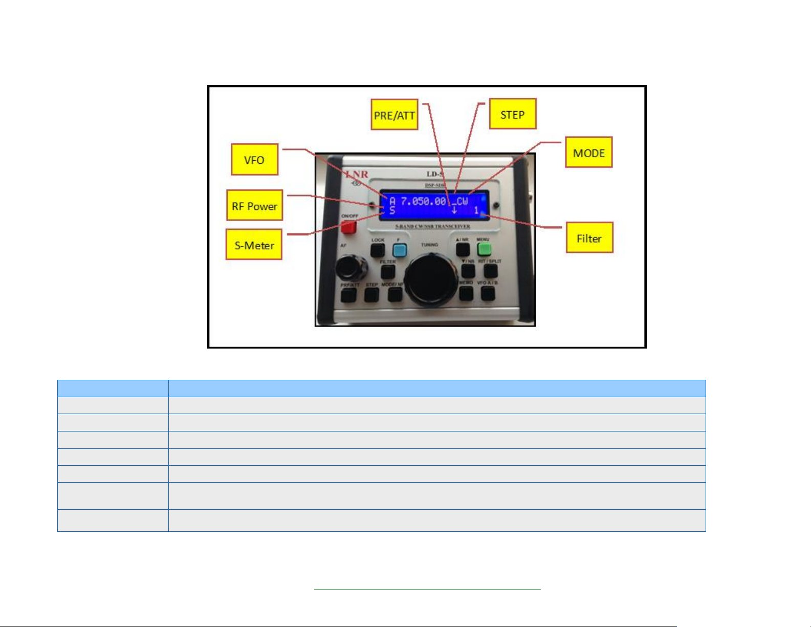
DESCRIPTION of the command buttons
Command
Meaning
ON/OFF
POWER ON/OFF the transceiver
UP Arrow ↑
Change Band higher 7/10/14/18/21. In Menu mode select next menu item
DOWN Arrow ↓
Change band lower. In menu mode select previous menu item.
MODE
Select CW/ CWR/ LSB/ USB/DIGI
VFO
Select either VFO A or B
STEP
Sequential pressing of the STEP button or the Tuning encoder steps through the tuning rate.
1 bar- 1Hz 2 bars=10Hz 3 bars=100Hz 4 bars=1KHz tuning rate.
LOCK
Lock/unlock the tuning dial ₣ symbol appears to the left of the mode designation on LCD
© 2014 LNR Precision Par EndFedz Antennas and QRP Transceivers
Page 8
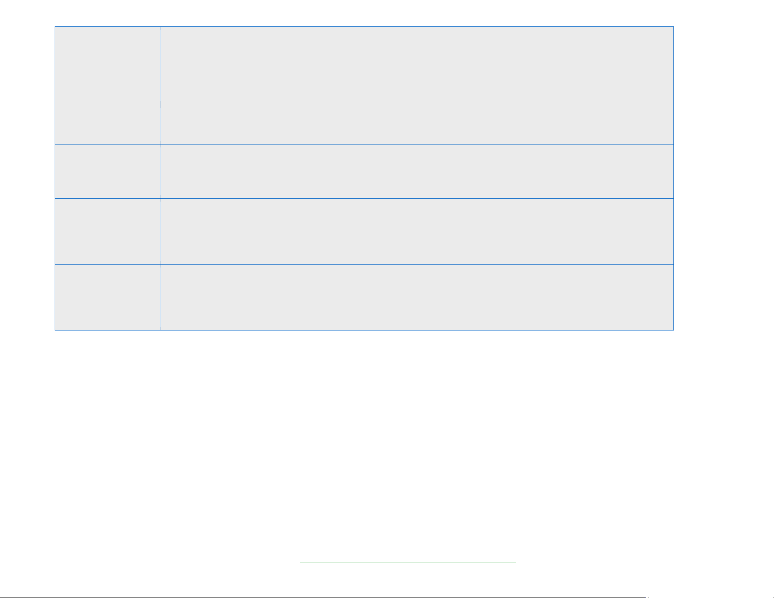
RIT
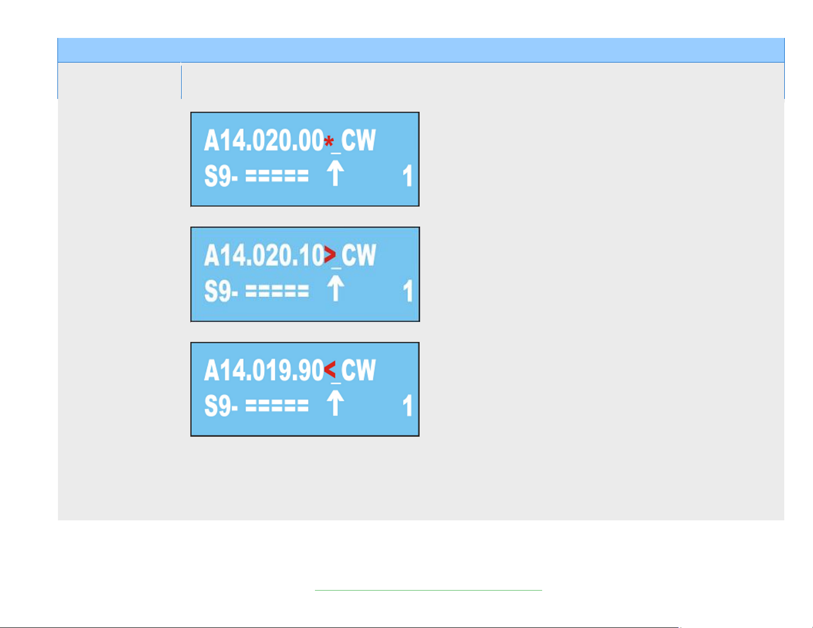
Receiver Incremental Tuning. This feature allows changing the frequency of the receiver only without effecting the transmit
frequency. When RIT is activated an * initially appears to the right of the frequency readout. The * indicates that currently,
RIT=0 or RX=TX.
While RIT is activated, tuning the VFO BELOW the current frequency is indicated by a< symbol.
Similarly, tuning above the center frequency results in a > symbol appearing to the right of the display.
RIT remains active until the next ON/OFF power cycle.
PRE/ATT
Sequentially enables preamp (↑) approx. +16dB
Preamp off= No arrow attenuator (↓) approx. -10dB
FILTER
Filter #4 is customizable in CW and SSB. CW from 50Hz 2400Hz SSB from Low end of 250Hz to High end of 3400Hz.
CW: Select Filter #4. Press F then Filter. Use the VFO knob to adjust bandwidth
SSB: Select Filter #4. Press F then Filter. Use the VFO knob to adjust the low end. Press RIT to adjust the High end. Pressing
RIT again will toggle back to low end adjust. Press Filter when complete.
Memory Storage
A total of 100 memories are available. All features (e.g. Mode/NB/NR/Preamp etc) are stored along with the frequency.
To store a frequency in memory, first tune it in using the VFO. Set Mode and any other features you wish to store. Press
MEMO Use the VFO knob to bring up the memory location you wish to store: 0-99
Press the Down Arrow ꜜ
Press MEMO again
Memory Recall
To recall a stored memory channel;
Press MEMO
Use the VFO to dial up the desired memory location
Press the Up arrow ꜛ
Press Memo again
© 2014 LNR Precision Par EndFedz Antennas and QRP Transceivers
Page 9

MENU Settings
MENU
Default menu settings
AGC
AGC speed from 1-20. 1 is the slowest and 20 the fastest
PITCH CW
Sidetone and CW offset pitch. Changes take effect when you exit Menu mode
CW SPEED
5 to 60 WPM. Speed change takes effect when you exit Menu mode.
WEIGHT CW KEY
Adjusts the ratio of dash length to dot length:
2> 1; 2.5> 1; 3> 1; 3.5> 1; 4> 1; 4.5> 1 3:1 is standard
CW VOX
Controls break in delay. Steps in 100mSec from 100mSec to 5 seconds
REVERSE CW KEY
Change which side of the paddle is dot and which side is dash.
CW KEY TYPE
Two options: SIMPLE= hand key. AUTO= Paddle.
IAMBIC MODE
Allows user to switch from Iambic mode A to Iambic mode B
NOTCH FILTER
Adjusts notch depth from -6 dB to -40dB Changes can be observed while in Menu mode.
NOISE BLANKER
Adjustable using tuning knob from 4 to 12. 4 is maximum blanking, 12 is minimum. Changes can be heard while in Menu mode.
NOISE REDUCTION
Menu range from 1 to 100 with 1 being the least. If NR is activated from the front panel (F + NR) you can observe the effect
within the Menu.
S-METER MODE
Two modes: Bar Graph or readout in uV.
TX METER
Two options: Bar Graph (Scaler) or Watts (Number)
SHOW TX
Two options: Power in Watts or VSWR
POWER TX
Adjusts power out. Settings from 10 to 100. Typically, a 10 setting is 1W and a 100 setting is 5W
LED MODE
Two options: Forever= LCD backlight always on. Auto= backlight turns on for 3 seconds whenever a front panel switch or encoder
is activated. Backlight off saves 40mA of current drain.
SSB TX MUTE
SSB TX Monitor. Two options: Enable and Disable
SSB COMPRESSOR
SSB Mic compression from 1 to 100.
SSB VOX
adjustment of VOX delay for SSB – DISABLE is off, Adjustable from 100mSec to 5 seconds in 100mSec steps
VOX LEVEL
Adjusts VOX gain in SSB mode.
TX EQ
3 options: Accentuate the Lows, Highs or Midrange. LowF /HiF/ MediumF
GAIN TX DIG
Setting from 1-9.8 using the VFO knob. This function controls the AF Gain in Digital mode
SQUELCH
Settings 0-100. A 0 (zero) setting essentially turns squelch off.
Enter MENU MODE by pressing MENU button and exit the menu mode by pressing the MENU again after set up.
Most of the functions, related to receiving or transmitting, can be changed by values and monitored via monitor in real time.
© 2014 LNR Precision Par EndFedz Antennas and QRP Transceivers
Page 10
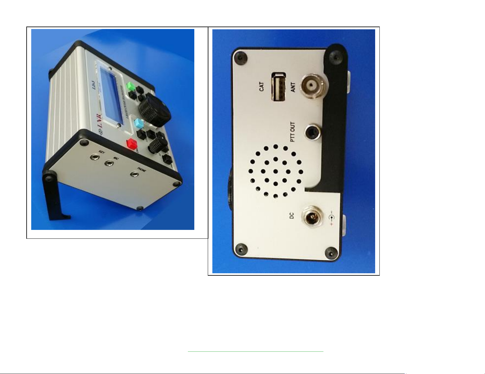
© 2014 LNR Precision Par EndFedz Antennas and QRP Transceivers
Page 11
FUNCION SETTINGS = PUSHING F + :
RIT
On virtual intermediate frequency (VIF) – can be set from the main menu from 5000 to 10000 hertz. Identified as arrows on the upper right
corner of the display ->. VIF is working as a main working feature and must be switched on permanently. DIRECT CONVERSION should be
used as an option.
On any VFO- when you push RIT an asterisk appears as shown:
When you move frequency up , an arrow will appear to the right:
When you move frequency down , an arrow will appear to the left:
SPLIT OPERATION
SPLIT MODE- if you want to receive on 14020.00 and transmit on 14030.00:
SET frequency on VFO A 14020.00 and on VFO B 14030.00
REMEMBER, first VFO chosen is an RX frequency:
PUSH RIT button, and then follow RIT MODE :
© 2014 LNR Precision Par EndFedz Antennas and QRP Transceivers
Page 12
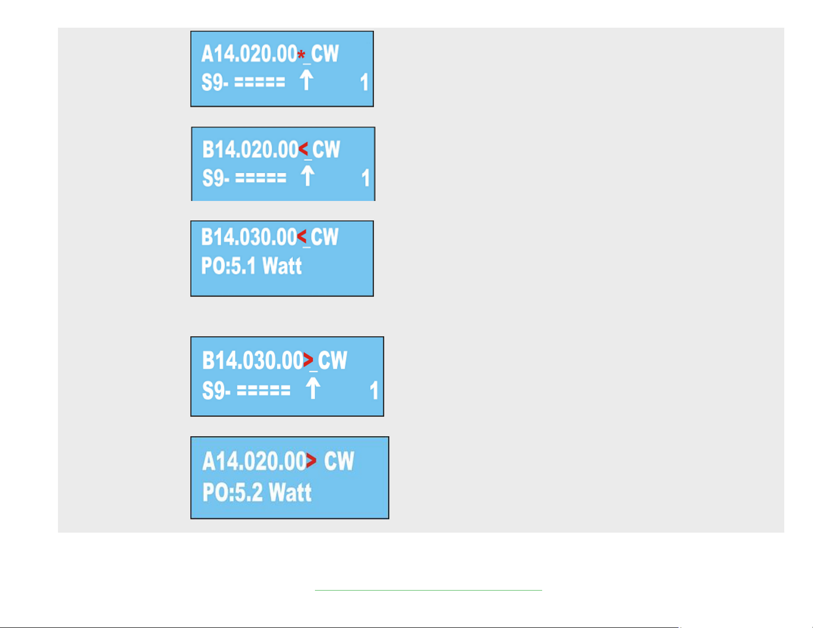
PUSH VFO A/B until VFO B appears, with reflecting RX frequency arrow to the left
If you switch on TX, the frequency on VFO B will appear – 14030.00
You will notice that VFO A frequency can move up/down, but VFO B is fixed on TX.
If you wish to reverse the frequency, exit RIT Mode and switch to VFO B, then push RIT and then VFO A.
Notice the arrow shows pointing to the right
On TX you will see this :
© 2014 LNR Precision Par EndFedz Antennas and QRP Transceivers
Page 13
MENU
Press (F)unction and then Menu. This changes the 2nd line of the LCD display from S meter reading to monitoring the supply voltage.
Pressing (F)unction and Menu again returns to S meter reading.
UP (ꜛ)
Press (F)unction and then ꜛ turns on Noise Reduction at whatever level is preset in the main Menu. The display will show a “R” to the left
of the Filter # on the LCD display. Press (F)unction and ꜛagain to turn off Noise Reduction
MODE
Available only in SSB mode. Press (F)unction and then Mode to enable the notch filter at whatever level has been preset in the main Menu.
Press (F)unction and then Mode again to turn off the notch filter. The letter “N” will display to the left of the Filter #.
DOWN (ꜜ)
Press (F)unction and then ꜜto turn on the Noise Blanker at whatever level has been preset in the main Menu. The letter “B” will display to
the left of the Filter # on the LCD display
FILTER
Filter #4 is customizable in CW and SSB. CW from 50Hz 2400Hz SSB from Low end of 250Hz to High end of 3400Hz.
CW: Select Filter #4. Press F then Filter. Use the VFO knob to adjust bandwidth
SSB: Select Filter #4. Press F then Filter. Use the VFO knob to adjust the low end. Press RIT to adjust the High end. Pressing RIT again will
toggle back to low end adjust. Press Filter when complete.
SERVICE MODE – It is strongly recommended to contact LNR Support before entering
service mode
Entry into service mode
To enter into default settings – switch OFF the radio and THEN power it up while F button is pressed. RADIO IS READY NOW!!!!
Upon entering the service mode, reset all the settings IN DEFAULT EXCEPT “RX IQ”, “TX IQ” and fine tuning of the synthesizer.
You should not go to factory settings “RX IQ”, “TX IQ” as they are set individually for your radio and precisely adjusted for values with
additional specialized devices, TRANSMITTING and measuring in certain frequency.
Each radio in the service menu is recorded INDIVIDUALY for serial number, factory settings “RX IQ”, “TX IQ” and is hard to adjust if you are
not aware of procedure!!!!!!!!!!!
© 2014 LNR Precision Par EndFedz Antennas and QRP Transceivers
Page 14

BASIC SETTINGS
F button and then press the MENU button and moving with UP / DOWN and RIT
IF DSP
Virtual gap frequency from 5006 to 10013 Hz / recommended to use a low-frequency virtual
V PWR
Adjustment of the displayed voltage
REF VFO
Correcting the VFO frequency
MULT VFO
Divider VFO. For LD-5 = 4 / do not touch it , it is correct by the service menu/
STARTING FREQUENCY
Low end frequency of selected band; change with tuning knob
END FREQUENCY
High end frequency of selected band; change with tuning knob
S METER
Setting S-METER for the range – calibration
RX IQ
Setting the mirror channel correcting the phase and amplitude of IQ for each band separately on RX “- minimum reading – has two modesfast and slow for quick setting and fine – switched with STEP.
Each transceiver is factory default recorded on the accompanying document
FILTER SSB
Setup filters from 1 to 3 for each type of work. Changing the filter with the push button “Filter”
FILTER CW
Allows user to change the bandwidth of the first three CW filters. While in Service Mode, press Menu. Select Filter 1 CW and redefine the BW
with the main tuning knob. Step to the next filter by pressing FILTER etc. Exit Menu mode to save.
AGC DSP
on / off AGC -SHOULD ALWAYS BE SET TO ENABLE
SHOW S METER
Switches S meter
FILTER TX SSB
Adjustment of bandwidth in the transmit mode /FROM 150 Hz to 3600Hz/ -. Changing adjustment of the upper frequency
FILTER TX CW
With the push button “RIT/VIF” adjustment of bandwidth in the transmit mode /FROM 50 Hz to 1000Hz/ - soft CW manipulation 50 – 180 Hz.
BELL SOUND
LEVEL TX
Adjustment of Power – entries are shown from “Power TX”- First row on Display: TX ADC indications power “when all bands are equal in
power”.
© 2014 LNR Precision Par EndFedz Antennas and QRP Transceivers
Page 15
DESCRIPTION of the settings in transmit mode
PWR / VTT
POWER TX
First row on Display: TX ADC indications power for each band separately.
Second row on Display : Power Control for each band separately, shows power of radio on TX – use forward wave of SWR meter
settings are made on a 50 ohms dummy load and SWR = 1, setting indication varies around 100 – 4000
TX IQ
Correcting amplitude and phase balance in IQ channel – in the transmit mode for each band separately
For this purpose we need to have a separate receiver on the frequency and listen to the unwanted side band channel – set on minimal
hearing. Factory setting on all bands is : A 0.0000 F 0,0000
TX EQ
3 band audio presets on transmit only: bass, middle. Treble boost
/ Those settings are directly accessible by pressing MENU /
AGC SPEED
ADJUSTABLE in levels of delay from 1 to 20
PITCH CW
CW tones from 400 to 1000 Hz when crossing the transmit shift to the same tone
NOTCH FILTER
Reject interfering tone only for SSB from -6 to -40 db
NOISE BLANKER
Adjusted in the range from value 4 to 12 - readings depending on interference
NOISE REDUCTION
Level of attenuation of the noise from 1 to 50- use minimal necessary
S-METER MODE
Shows scale bars or S-units in microvolt’s
LED
Backlight brightness of the LCD from 0 to 250
CW SPEED
Regulating the speed of the automatic key from 20 signs to maximum
WEIGHT CW KEY
Dot-dash ratio 2.5> 1 to 4.5> 1 in 0.5
CW VOX
DELAY mode in CW - 100 milliseconds to 5000 milliseconds / 5 seconds /
COMPRESS TX
Compression microphone from 0 to 100%
REVERSE CW KEY
Reversing dot-dash to paddle
TX METER
Shows SWR or power in the transmit mode with bar graph or scale figures
SHOW TX
SWR or power to be displayed in the transmit mode
POWER TX
Regulation in mW from 10% to 100%
LED MODE
Mode for backlight LCD - constant or relight by pressing any button or rotating of tuning knob
SSB MUTE
on / off microphone - MONITOR mode in transmit
DESCRIPTION of the current settings
© 2014 LNR Precision Par EndFedz Antennas and QRP Transceivers
Page 16
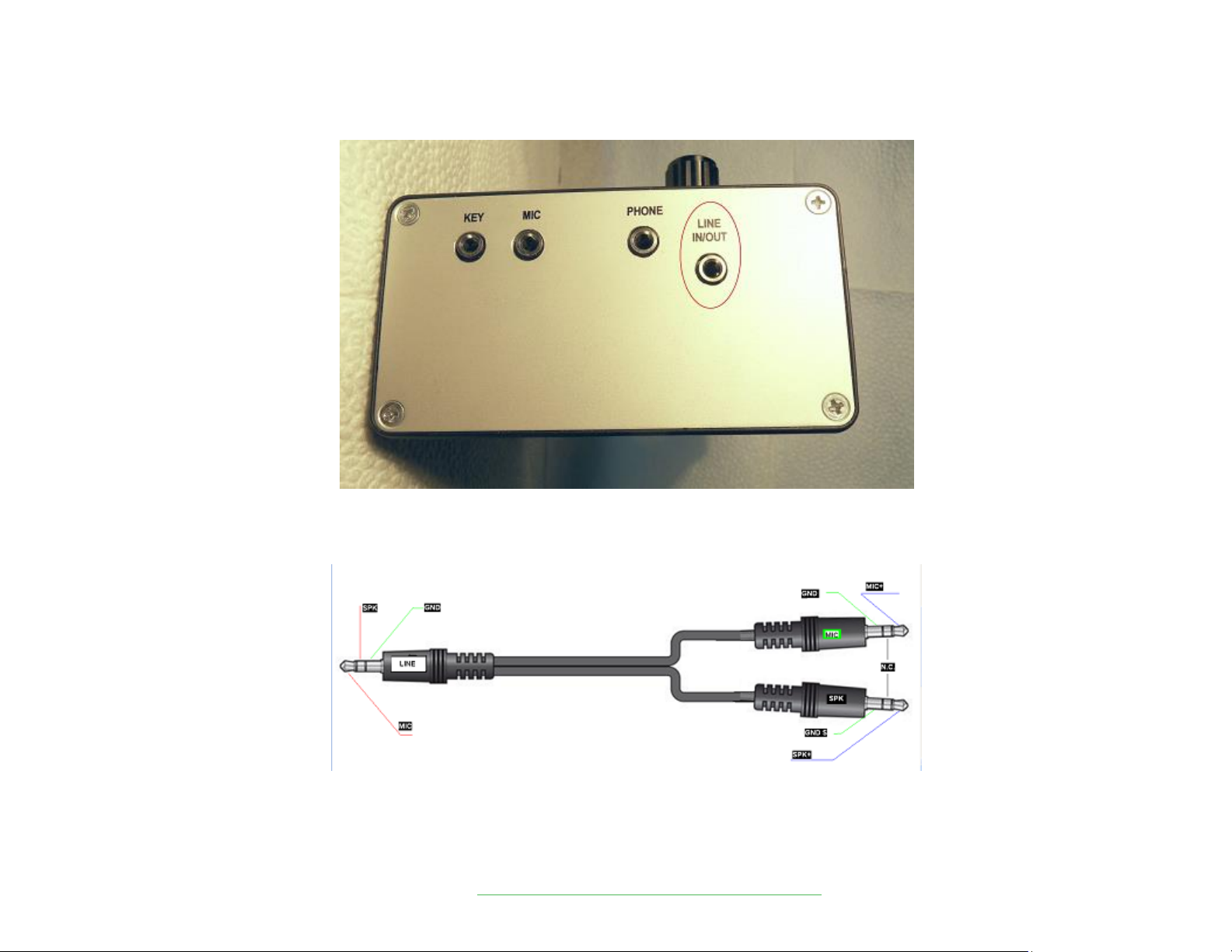
DIGITAL MODES
IMPORTANT – Make sure to connect the USB, Power Cord and Antenna before powering on the radio.
Then Power ON the Radio. Finally, start up your software program:
In order to operate digital mode or interface with computer, utilize the Line IN/OUT jack and cable. The radio has typical levels for audio signals similar to other amateur
radios.
© 2014 LNR Precision Par EndFedz Antennas and QRP Transceivers
Page 17

SWR Protection
The radio has a built-in ALC SWR protection - when SWR does not exceed 1:3 – there is no change in output power.
But at a greater SWR, the protection gradually lowers the power output, and at SWR = 10 – the output power is only 1%.
================================================== ======================================
EXPANDED RECEIVE CAPABILITIES
The LD-5 can be set to receive 160M and 80M. At this time, this is for receive only, no TX.
1. Put the LD-5 on 40M.
2. Enter Service Menu
3. Use the UP and DOWN arrow keys to bring up (Begin Frequency 2 Band)
4. Using the VFO knob to tune to 1.8MHz. Pressing the Step button will enable faster QSY.
5. Exit Service mode
6. Use the VFO knob to tune to 7.300MHz and as you go higher the VFO will roll over to 1.8MHz.
7. Select a frequency and mode on 160M and store this frequency into a memory location.
8. Tune up to 80M and do the same for a memory location.
9. Tune to 40M and store a memory location.
When the 40M band is selected with the UP and DOWN arrows, use the Memory function to recall 160, 80 or 40M bands.
© 2014 LNR Precision Par EndFedz Antennas and QRP Transceivers
 Loading...