

Page 1
$
$
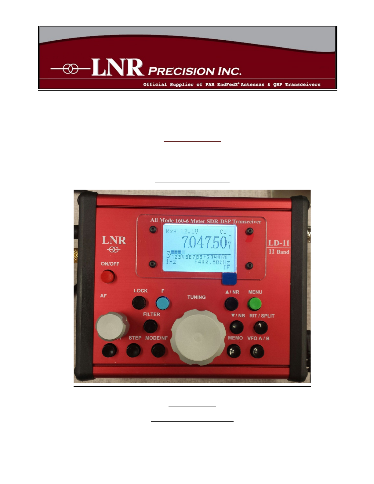
LD$-11$
HF$+$6m$DSP$SDR$
QRP$Transceiver$
$
USER$Manual$
(Preliminary)$Ver.$1.0.1$
$
$
Page 2

TABLE$$OF$$CONTENTS$
1. TABLE$OF$CONTENTS$.$.$.$.$.$.$.$.$.$.$.$.$.$.$.$.$.$.$.$.$.$.$.$.$ 2$
2. INTRODUCTION$.$.$.$.$.$.$.$.$.$.$.$.$.$.$.$.$.$.$.$.$.$.$.$.$.$.$.$.$ 3$
3. SPECIFICATIONS.$.$.$.$.$.$.$.$.$.$.$.$.$.$.$.$.$.$.$.$.$.$.$.$.$.$.$.$ 4$
4. ACCESSORY$PACKAGE.$.$.$.$.$.$.$.$.$.$.$.$.$.$.$.$.$.$.$.$.$.$.$ 7$
5. PANEL$CONTROLS$&$CONNECTIONS$.$.$.$.$.$.$.$.$.$.$.$$ 8$
5.1 FRONT$PANEL.$.$.$.$.$.$.$.$.$.$.$.$.$.$.$.$.$.$.$.$.$.$.$.$ 8$
5.2 SIDE$PANELS.$.$.$.$.$.$.$.$.$.$.$.$.$.$.$.$.$.$.$.$.$.$.$.$.$ 10$
6. OPERATION$.$.$.$.$.$.$.$.$.$.$.$.$.$.$.$.$.$.$.$.$.$.$.$.$.$.$.$.$.$.$.$ 11$
6.1 $GENERAL$OPERATION.$.$.$.$.$.$.$.$.$.$.$.$.$.$.$.$.$ 11$
6.2 $RECEIVE$OPERATION.$.$.$.$.$.$.$.$.$.$.$.$.$.$.$.$.$.$ 13$
6.3 $TRANSM IT$$OPERATION$.$.$.$.$.$.$.$.$.$.$.$.$.$.$.$$ 16$
• GENERAL$TX$$OPERATION$.$.$.$.$.$.$.$.$.$.$.$ 16$
• MODE-SPECIFIC$OPERATION.$.$.$.$.$.$.$.$.$ 17$
o SSB$OPERATION$.$.$.$.$.$.$.$.$.$.$.$.$.$.$.$.$ 17$
o CW$$OPERATION$.$.$.$.$.$.$.$.$.$.$.$.$.$.$.$.$ 18$
o DIGITAL$MODES$OPERATION$.$.$.$.$.$ 19$
o RTTY$$OPERATION.$.$.$.$.$.$.$.$.$.$.$.$.$.$.$ 19$
o AM$&$FM$OPERATION.$.$.$.$.$.$.$.$.$.$.$ 19$
7 SOFTW ARE$MENU$MODE$SETTINGS$.$.$.$.$.$.$.$.$.$.$.$ 20$
8 SERVICE$MODE$.$.$.$.$.$.$.$.$.$.$.$.$.$.$.$.$.$.$.$.$.$.$.$.$.$.$.$.$.$23$
9 INDE X .$.$.$.$.$.$.$.$.$.$.$.$.$.$.$.$.$.$.$.$.$.$.$.$.$.$.$.$.$.$.$.$.$.$.$.$.$$27$
Page 3

IMPORTANT MESSAGE
Operating an Amateur Radio Transmitter/Transceiver requires an
Amateur Radio License in ALL Countries! Operating the LD-11 without a
valid Amateur Radio License is punishable by law in ALL Countries.
INTRODUCTION
The LD-11 is 11-Band, All-Mode
transceiver is a synthesis of a modern
SDR/DSP technology and ease of use.
It supports nearly all of the features
of much higher priced SDR
transceivers, has command and
functional knobs, and it is easy to use
and requires no computer for
operation.
The LD-11 comes with advanced DSP
features such as user-definable razorsharp filters, Noise Reduction (NR),
Noise Blanker (NB), Notch Filter (NF)
and adjustable AGC timing.
The LD-11 also incorporates a
BANDSCOPE which displays 24 kHz
above and below the operating
frequency. This helps find stations on
a quiet band, or locate a free spot on
a crowded band.
LD-11 5 Watt transmitter comes
with a hand mike and produces one of
the cleanest signals on the air. It
includes features such as Speech
Processor, Dual-Mode CW/CWR,
built-in Iambic Keyer supporting A/B
modes of keying and full metering of
output power and SWR. External amp
keying is available through a
dedicated RCA Phono (Cinch) jack.
The LD-11 has audio equalizing for
both RX and TX, RIT and XIT, and of
course dual VFOs. It includes a USB
CAT-Control with FTDI decoder, LINE
- - - - - - - - - - - - - - - - -
PLEASE STUDY THIS MANUAL
BEFORE BEGINNING OPERATION
This radio requires the
following things:
• A valid Amateur Radio License
authorizing operation on the HF
Amateur Radio bands.
• A regulated power source
(power supply or battery)
supplying nominal 12.6vdc @ 2
Ampere. (Note: 10.5v minimum
to 14.0V maximum).
• A (nominal) 50 Ohm Antenna on
the band(s) of operation.
• OPTIONAL:
• Stereo Headphones (4 to 64
Ohms).
• Morse Code Straight Key or
Paddle.
Page 4
4"
SPECIFICATIONS
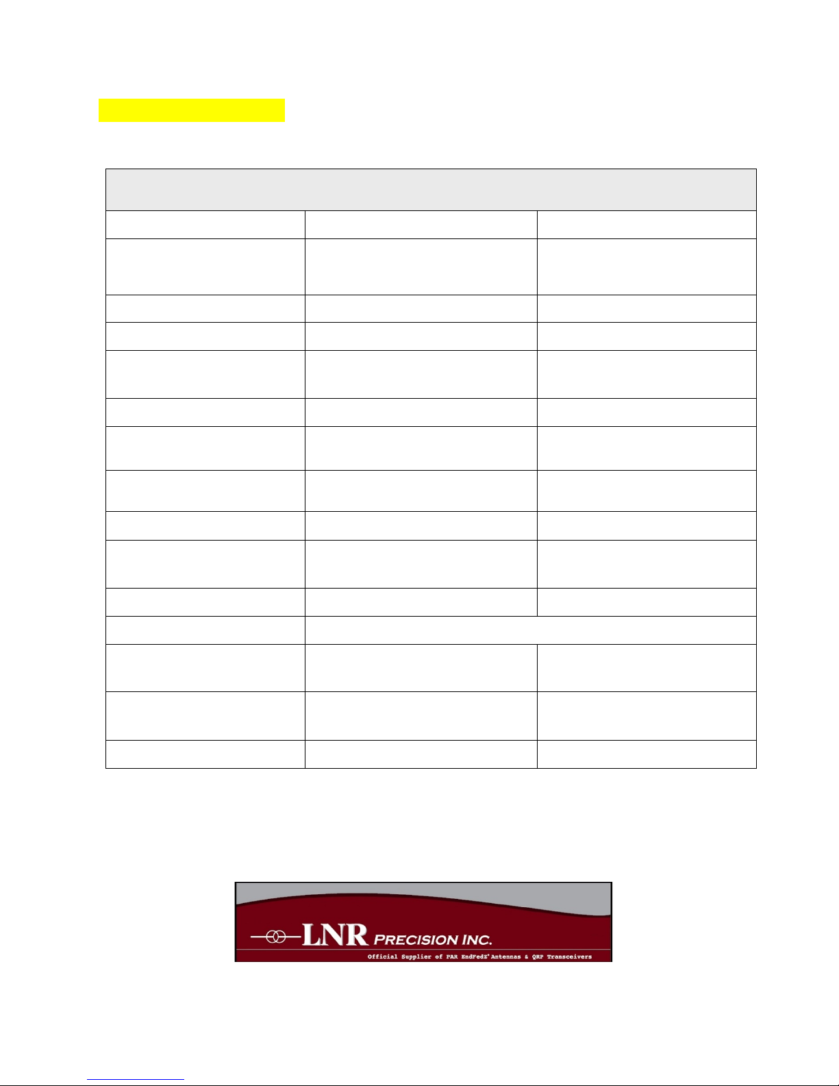
GENERAL TRANSCEIVER SPECIFICATIONS
Technology
Solid State SDR-DSP
Direct Conversion
Frequencies / Bands
1.8 MHz to 54.0 MHz
160, 80, 60, 40, 30, 20, 17,
15, 12, 10, 6m
Modes
AM, CW, DIGI, FM, LSB, USB
CAT: USB2 (FTDI Chip)
Digital Modes
JST, PSK, RTTY, SSTV, etc.
LINE IN/OUT 3.5mm Jack
Output Power
5 Watts (typical)
(fold-back protection for high
SWR)
Antenna
50 Ohms (nominal)
BNC Connection
Voltage Requirements
10.5vdc (min) to 14vdc (max)
Fuse: 3.15A, 250V, Slow
Blow
Current Drain
RX: Average 360mA
TX: Maximum 2A
RX 40mA less with the
backlight switched off
Frequency Stability
±3 ppm
0 to 50 degrees Centigrade
Memory
100 slots (0-99)
stores freq., mode, VFO
(A/B) & other functions
Loud Speaker
1/4 Watt
Display Backlight
Always On, Always OFF, Automatic (off after 3 seconds)
Enclosure Size
12.8 x 10.7 x 5.5 cm
(excluding knobs and
connectors)
Working Size
14.7 x 10.7 x 7 cm
(including knobs and
connectors)
Weight
580 grams (20.5 oz.)
(without mic)
Page 5
5"
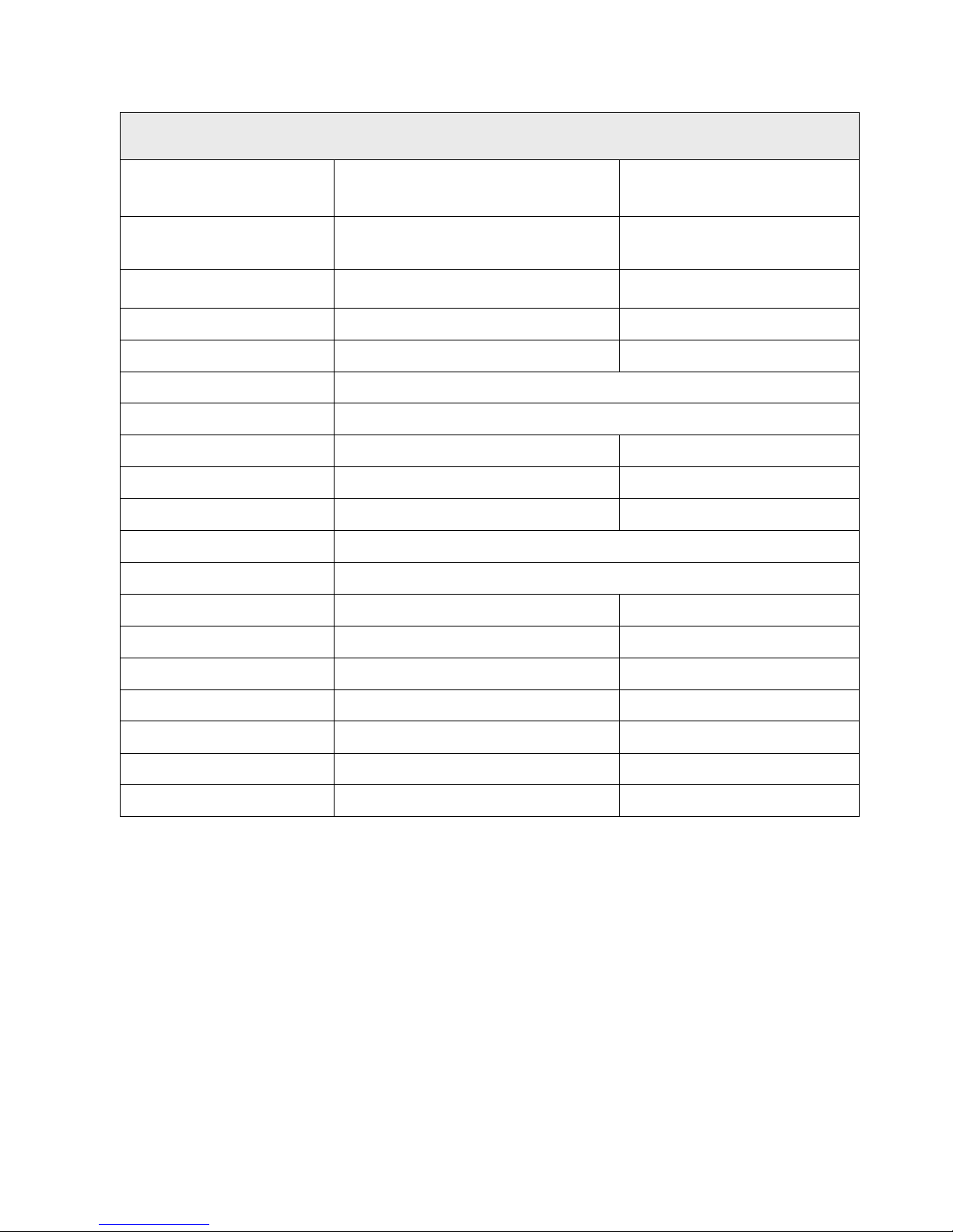
TRANSMITTER SPECIFICATIONS
Output Power
5 Watts (typical) / adjustable
(fold-back protection for
high SWR)
TX Metering
Selectable: Output Power or
SWR
Selectable: Numerical or
Bar Graph
D.C. Voltage
Metering
Numerical display
VOX
Adjustable Gain & Delay
Compressor
Adjustable 0-20dB
SSB TX Mute
Disable = Monitor / Enable = Mute
Key Type
Selectable: Automatic = Paddle / Manual = Hand-Key
Built-In Keyer
Iambic Mode A or Mode B
Menu selectable
Keyer Adjustments
Speed / Weight
Menu adjustment
CW Sequencing
Adjustable Delay
From 100ms to 5 seconds
Digi Mode Gain
Adjusts audio gain in digi mode
AMP Key (PTT JACK)
Keys External Amplifier
TX DSP FILTERS
1 Filter per Mode
SSB TX Filters
Bandwidth: 2.800 kHz
Adjustable
CW TX Filters
Bandwidth: 100 Hz
Adjustable
AM TX Filters
Bandwidth: 5.590 kHz
Adjustable
FM TX Filters
Bandwidth: 9.600 kHz
Adjustable
DIGI TX Filters
Bandwidth: 3.350 kHz
TX Bandscope
Monitors transmitted signal
"
Page 6
6"
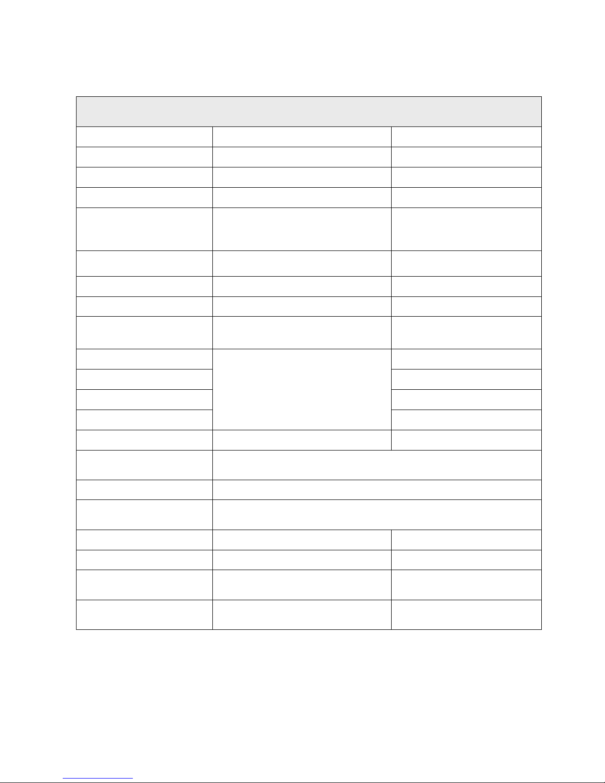
RECEIVER SPECIFICATIONS
Technology
Solid State SDR-DSP
Direct Conversion
Sensitivity
0.2 uV
With Preamp On
Preamp
+20 dB
Attenuator
-12 dB
Pre-Filtering
7 LPF and 7 BPF (cascaded)
160m, 80m, 60+40m,
30+20m, 17+15m,
12+10m, 6m
Spurious Response
…Rejection
IMD3: -48 dB
Current Drain
Backlight: ON / OFF
Avg. 360mA / 320mA
RX Bandscope
±24 kHz
DSP RX Filters
4 filters (most modes)
1 is user definable
push-button selection
SSB Filters (4)
4 Filters:
• 3 Fixed Filters
• 1 User Adjustable Filter
From 250 Hz to 3600 Hz
CW Filters (4)
From 50 Hz to 2400 Hz
AM Filters (4)
From 2.0 kHz to 9600 Hz
FM Filters (4)
From 2.0 kHz to 9600 Hz
DIGI Modes (1)
Bandwidth
Fixed: 3.35 kHz
DSP Noise
…Reduction
Adjustable Level (1 to 100) use lowest level necessary
DSP Noise Blanker
Adjustable Level (4 to 12) Adjust for minimum interference
DSP Notch Filter
Carrier Eliminator, SSB mode (only), (greater 6 -40dB)
S-Meter
Bar Graph or uV readout
CW Mode Selection
CW or CWReverse
Menu selectable
Squelch SSB/CW
Adjustable for
SSB/CW/AM/DIGI Modes
0 to 100 / "0" = Off
Squelch FM
Adjustable for
0 to 100 / "0" = Off
Page 7
7"
ACCESSORY PACKAGE
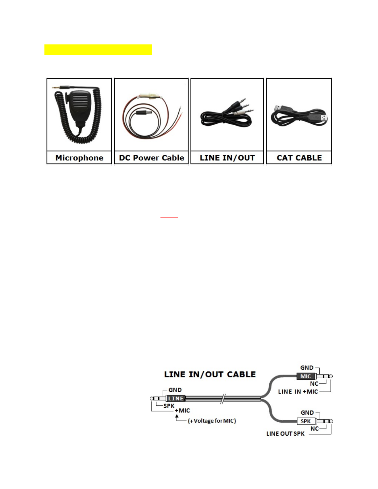
The LD11 ships with the following accessories:
Microphone: An electret mic that
draws its power from the mic line (tip).
/If you use a dynamic mic, you must
insert a 350 to 400 nF capacitor
between YOUR mic capsule and this
line/.
DC Power Cable: Red (+) and Black
(-) power cable with in-line fuse holder
and coaxial power plug (2.5mm x
7mm).
Spare Fuse: (not pictured) a spare
fuse is included in the accessory
package. It is a 5mm x 20mm fuse,
3.16A, 250V Slow-Blow.
USER MANUAL
CAT CABLE: This is a standard
computer USB2 cable with type A plugs
on both ends.
2 ALLEN WRENCHES: (not shown)
LINE IN/OUT: This is a special cable
which splits the input audio and output
audio from a single common plug and
connects each to its own dedicated
plug.
All three plugs are 3.5mm phone plugs.
See pinout below:
Page 8
8"
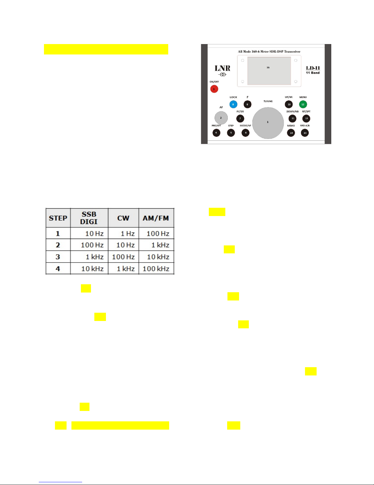
FRONT PANEL CONTROLS
1. VFO-TUNING / Multi Knob;
Adjusts frequency in operation
mode;
Adjusts menu value in Menu mode.
2. AF Gain Control
3. Power ON/OFF
4. PRE/ATT – pushing button toggles
through Preamp, Attenuation, or
None
5. STEP – selects the step size
(tuning rate) when turning the VFO
knob.
6. MODE /NF – pushing this button
toggles through the modes (USB,
CW, etc.). In SSB Mode (only):
when the [F] button is pushed,
followed by the Mode button, it
toggles the Notch Filter on or off. It
is always off in all other modes.
This is also called “ACE”.
7. FILTER – pushing this button steps
through the selection of bandwidth
filters 1, 2, 3, or 4.
8. LOCK/TX – pushing this button
locks the VFO knob; pushing first
[F], and then pushing this button
places the transceiver in transmit
(TX) mode. Repeat the process to
exit transmit mode and return to
receive mode (RX).
9. [F].– Function Button; pushing
this button activates the 2nd layer of
functions for each button.
10. UP/NR – in operating mode,
pushing this button changes the
band to the next higher band. In
MENU mode, pushing this button
selects the next higher menu item.
Push [F] and this button to activate
the DSP Noise Reduction.
11. DOWN/NB – in operating mode,
pushing this button changes the
band to the next lower band. In
MENU mode, pushing this button
selects the next lower menu item.
If pushed after pushing [F], it
activates the DSP Noise Blanker.
12. MENU – Pushing this button enters
the software Menu Mode.
13. RIT/XIT – Pushing this button
enables Receive Incremental Tuning
Page 9
9"
(RIT). Pushing [F] first and then
this button enables TX Incremental
Tuning (XIT). In some menu items,
this button also is used to toggle
between multiple parts of the item
(i.e. defining filter settings, etc.).
14. MEMO – Pushing this button
enables storing and recalling
memory locations.
15. VFO/PAN – Pushing this button
toggles between VFO-A and VFO-B.
Pushing [F] and then this Button
enables turning the PAN-ADAPTER
on and off. Select with VFO knob.
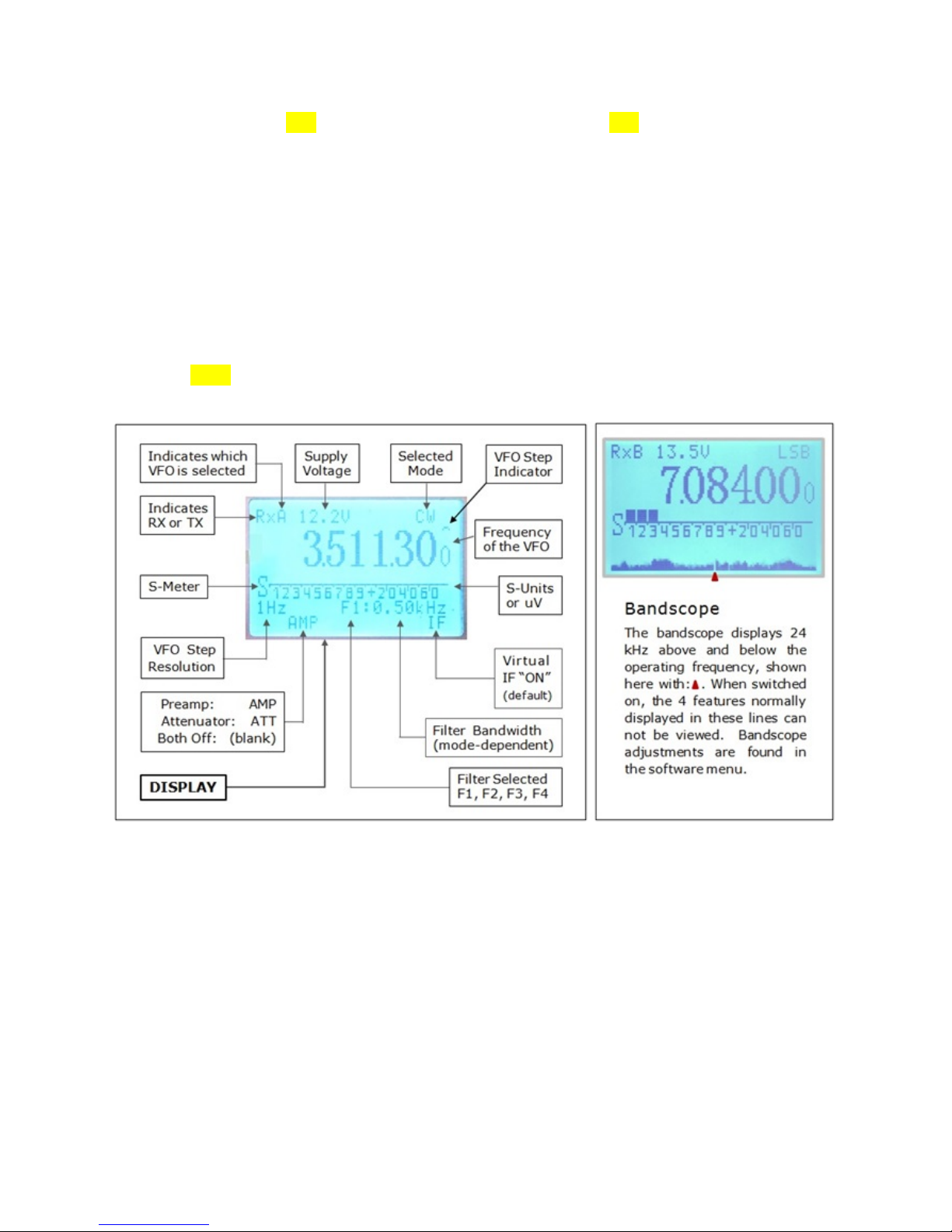
16. DISPLAY – LCD display size is 43.5
x 40.9mm (1.7” x 1.6”). It has very
low power consumption.
The pictures (below) describe most
of the features which are displayed
on the LD-11 display.
Page 10
10"
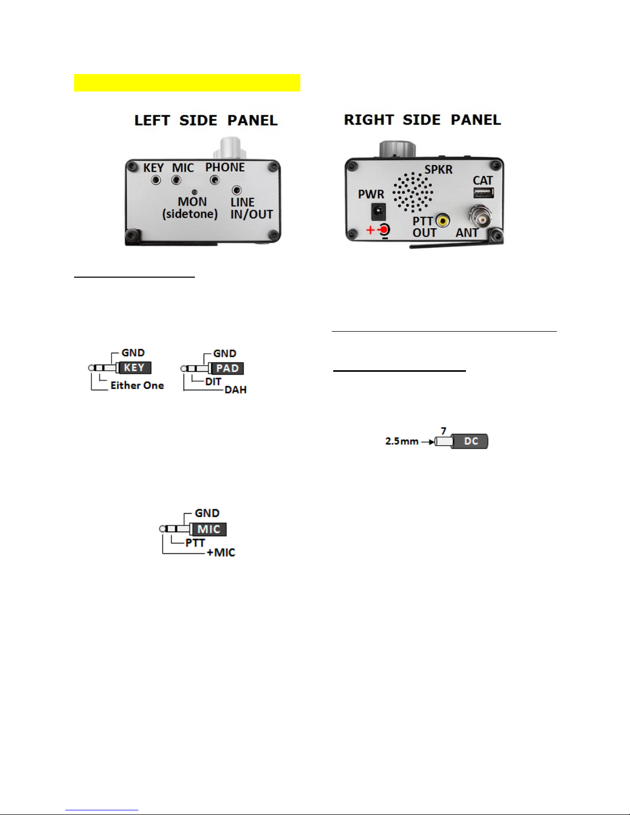
SIDE PANEL CONNECTIONS
Left Side Panel
KEY: The LD-11 accepts either a
Straight Key or Paddle. Both connect
to the 3-pole, 3.5 mm key jack.
MIC: The LD-11 comes with a
condenser (electret) hand Microphone
using a 3.5mm phone jack. To use a
dynamic MIC, you must insert a 330 to
470 nF capacitor in series with the
+MIC line.
PHONE: The LD-11 accepts stereo
headphones with a 3.5mm phone jack.
Any common stereo headphones with
an impedance of 4 to 64 Ohms will
work; the lower the better.
SIDETONE: Adjust sidetone volume
level (through the hole) with a tiny
screwdriver.
LINE IN/OUT: Used for connecting to
external sound card interface. See
accessories page for pinout. Audio
level is independent of volume control.
Right Side Panel
DC: Power is applied through a
2.5mm x 7mm coaxial DC power plug.
ANT: A female BNC jack accepts
nominal 50 Ohm antennas.
CAT: CAT control is via a ‘type A’ USB2
connection. (FTDI Chip).
PTT: Push –To-Talk, open collector
keying circuit, used to key a linear
amplifier through an RCA phono plug.
(Also called Amp Key). Delay time is
adjustable in the software menu “CW
VOX”.
SPKR: Loud-Speaker, automatically
mutes when you plug headphones into
the phone jack.
Page 11

11"
OPERATION /GENERAL
BEFORE YOU BEGIN
• Assure that your antenna is in good
working order and properly
connected to the radio.
• Switch ON the power supply or
connect battery leads BEFORE
switching the radio on.
• Check that the supply voltage is
within the specified working range
required for proper operation.
(+10.5 to +14.0 vdc).
• Reduce the audio gain (turn gain
control almost fully counter
clockwise).
• Turn the radio ON and observe the
dial. The LD-11 logo should appear
for 1 seconds, and then the radio
switches to operate mode.
GENERAL INFORMATION
The LD-11 has only two primary
controls: the audio gain knob and the
VFO knob.
Audio Gain Knob: This is a
mechanical control with only one
function – to control the audio output
level to the speaker or headphones.
Full Counter ClockWise (CCW) is the
lowest gain setting, full ClockWise
(CW) is the maximum gain setting. The
position of this control does not affect
the audio output level on the LINE
IN/OUT jack.
VFO Knob: The VFO knob is used for
multiple functions:
1. Changing the operating frequency.
2. Changing software menu values
when operating in Menu Mode.
3. Changing the Receive Incremental
Tuning (RIT) frequency or Transmit
Incremental tuning (XIT) when
either of these functions is enabled.
Explanation of each of the VFO
function:
1. Turning the VFO knob is the basic
means of changing the operating
frequency. Turning the knob in the
CW direction increases the
frequency, and turning it in the CCW
direction decreases the frequency.
2. Most software menu items have
variable parameters that are
adjustable with the VFO knob. For
instance in RX mode you can vary
the level for the Noise Blanker or
the Noise Reduction, etc. For TX
you can vary the level of the speech
processor or the speed of the
automatic keyer in CW, etc.
Some menu items are simply
switched (toggled) between 2 or
3 positions, such as selecting
whether to show Output Power or
SWR in TX mode, or whether to
show S-Units or uVolts in RX
mode, etc. For a more detailed
explanation, see the Menu Mode
Settings on page 20.
3. When RIT is enabled by pushing the
“RIT” button, rotating the VFO
Page 12

12"
knob changes only the Receive
frequency, it does not change the
Transmit frequency.
You must be in TX mode to enable
XIT. Press [F] then the RIT button.
Rotating the VFO knob changes only
the Transmit frequency, it does not
change the Receive frequency.
The [delta] change in frequency
when rotating the VFO knob can be
observed on the top right of the
DISPLAY, as seen here:
………………………………………………………………………………………………………………………………………..
STATUS |ß------ DISPLAY ------à| COMMENTS
• RIT OFF: | RxA 13.1V LSB|
• RIT ON: |RxA 13.1V RIT * LSB| RIT = 0
• RIT ON: |RxA 13.1V RIT < LSB| RIT lower than VFO QRG
• RIT ON: |RxA 13.1V RIT > LSB| RIT higher than VFO QRG
………………………………………………………………………………………………………………………………………..
When RIT and XIT are both off,
there is nothing displayed. Turning
either one “ON” will show the “RIT”
(or “XIT”) in the space between the
voltage and the mode as shown
under DISPLAY above. The symbol
after RIT (or XIT) shows which way
the incremental tuning is moving.
<=down -or - >= up.
There is no function to re-sync the
RIT with the VFO’s frequency. If
you wish to do so, you must
manually tune it until the asterisk
(*) appears.
To exit RIT or XIT, simply push the
button again.
BAND SELECTION
Band selection is accomplished by
using the UP or DOWN arrows, just to
the right of the VFO knob. The band
order is:
160m|80m|60m|40m|30m|20m
|17m|15m|12m|10m|6m
With each press of a button, the radios
steps up or down by one band.
DISPLAY BACKLIGHT
Software Menu item “LED Mode”:
The options are: OFF, Always ON, or
automatic (off after three seconds).
When off, it saves about 40 mA of
current.
Page 13

13"
RECEIVE OPERATION
MODE SELECTION
There are two groups of modes:
• CW|CWR|DIG|AM|FM|USB|LSB
(AM/FM Enabled)
• CW|CWR|DIG|USB|LSB
(AM/FM Disabled)
You can choose which group you prefer
in Menu “AM/FM Mode” .
NOTE: each band can and must be
adjusted separately. Selection is
stored by band. Turning AM/FM “OFF”
on the 160 through 12m enables faster
stepping through the usable modes on
these bands.
FILTER SELECTION AND
ADJUSTMENT
The LD-11 has 4 filters per mode in
AM/CW/FM/SSB (F1, F2, F3, & F4).
There is only one filter for DIGI mode
with a fixed bandwidth of 3.35 kHz.
On all other modes, F1, F2 & F3 are
fixed bandwidths and are not user
adjustable. F4 is user-adjustable to
any convenient bandwidth and may be
adjusted without exiting Operating
Mode.
The bandwidth of the selected filter is
shown in kHz on the display, preceded
by the filter number. Example:
“F1: 2.9 kHz” or “F4: 0.1 kHz”.
In CW and SSB modes you can also
change the passband center frequency
as well as the bandwidth. This is not
necessary in AM or FM.
In CW mode, this is accomplished by
setting “CW PITCH” in Menu “Pitch
CW”. The bandwidth of the filter
selected is then centered on that
frequency.
In SSB mode (LSB or USB), this is
accomplished by setting the Lo-Cut and
Hi-Cut frequencies; the bandwidth is
then the difference between these two
frequency, the passband center is the
determined by the Hi-Cut frequency
minus half of the passband bandwidth.
Example follows below.
F4 Filter Adjustment:
For AM/FM & CW, filter adjustment is
simple. While in operate mode:
• Select the filter F4.
• Press [F] (blue button)
• Press [Filter] (the current
bandwidth appears)
• Rotate the VFO knob to adjust
the bandwidth (CW=wider,
CCW=narrower). Changes are
heard in real-time, but not yet
saved.
• Once the desired bandwidth is
set, save the change by pressing
the “Filter” button again.
EXAMPLE-1: Say we want a 100 Hz
CW filter centered on 650 Hz:
• Select CW Mode
• Select filter “F4”
• Press [F] , then press [Filter]
• Press “RIT” to toggle between
Lo- and Hi- adjustments – Use
VFO knob to adjust frequency.
• Set the bandwidth to 100 as
described above.
Page 14

14"
• Set the center frequency of the
passband for the CW filter in
Menu Mode “Pitch CW”.
Push “MENU”, then using the UP
or DOWN arrows, scroll to “Pitch
CW”. Adjust the VFO knob to
650. Press [MENU] to exit and
save settings.
The SSB F4 filter’s bandwidth and
passband are also easy to adjust.
The filter is adjusted by re-defining the
“Low Cutoff Frequency” and “High
Cutoff Frequency” of the filter’s
passband. The parameters are set as
follows:
• Bandwidth: difference between
the two frequencies (Hi Freq. –
Lo Freq.).
• Passband Center: Hi Freq.
minus half the bandwidth
frequency.
EXAMPLE-2: Say we want an SSB
filter 1.8 kHz wide, centered on 1.5
kHz:
• Select USB Mode
• Select filter “F4”
• Press [F], then press “Filter”
• Press [RIT] to toggle between
Lo- and Hi- adjustments – Use
VFO knob to adjust frequency.
• Set Lo-Freq. to 600 Hz ; Set HiFreq. to 2.4 kHz
• Passband Center is: 2400 Hz
minus 600 Hz = 1500 Hz
• Digital Modes: Most DIGI
modes are operated in DIGI
Mode PSK
,RTTY,SSTV,FT8,JT65,JT9 and
other with a fixed filter
bandwidth of 3.35 kHz.
OTHER DSP OPTIONS
Noise REDUCTION <NR>: The NR is
used to help reduce the level of
received broadband noise. It is
engaged by pressing [F] and then
pressing the [UP/NR] button. The NR
should be left OFF unless absolutely
necessary, as it will slightly distort
received audio when ON.
The level of noise reduction of the NR
may be adjusted in the software
menu, with a range of 1 to 100. 1 is
minimum and 100 is maximum. You
should only use as high of level as
deemed necessary. This helps keep
audio distortion to a minimum. To
deactivate the NR, press [F] and
[UP/NR] again.
NOISE BLANKER <NB>: The NB is
useful for reducing the level of short
pulse noise, such as static crashes or
pulses generated from an electric
fence. It is engaged by pressing [F]
and then pressing the [DOWN/NB]
button. The level of blanking can be
adjusted in the Software Menu, with
levels ranging from 4 to 12. In this
case, 4 is maximum blanking and 12 is
minimum blanking. Always set this
level as high as possible while still
achieving the necessary blanking. To
deactivate the NB, press [F] and
[DOWN/NB] again.
NOTCH FILTER <NF>: The NF
(“ACE”) is used for eliminating
carriers/heterodynes while operating
in SSB mode (only). It does not work
in any other mode. The level of noise
reduction of the NF may be adjusted in
the software Menu, with a range of 6
to 40 db.
Page 15

15"
It is activated by first pressing the [F]
button and then pressing the [MODE]
button. To deactivate NF, press [F] and
[MODE] again.
RECEIVER SENSITIVITY
There are 3 levels of receiver
sensitivity:NORMAL; ATTENUATION;
PREAMPLIFIER.Toggle through these
3 levels by pressing the “PRE/ATT”
button. The level selected is shown in
the bottom line of the display as: “AMP”
for Preamp; “ATT” for Attenuator; or
blank (nothing shown) when in
“NORMAL” mode.
AGC TIMING: The attack and
recovery time of the AGC is set in
the Software Menu “AGC”. The
range is from 1 (slowest) to 20
(fastest). Use slower speeds for
SSB and faster speeds for CW and
digital modes.
S-METER OPTIONS
The signal strength of the received
station may be displayed in S-Units on
the bar-graph display, or numerically in
uVolts. The S-Meter mode is set in the
MENU “S-METER MODE”.
AUDIO OPTIONS
AUDIO EQUALIZER: The received
audio may be adjusted in three
frequency ranges: Low/Medium/High.
It is adjusted in the Software Menu
“EQ RX”. Once has been selected, you
may step through the three ranges by
pressing the [RIT] button. The level is
adjusted using the VFO knob. The
range is 1 to 10 with 1 deemphasizing
the range (minimum) and 10
emphasizing the range (maximum).
Adjust to suit your own preference.
SQUELCH-FM: The squelch level for
FM is adjusted in the Software Menu
“SQUELCH- FM”. The range is 0 to
100. When set to 0, the squelch is off.
Adjust to suit your own preference.
SQUELCH-SSB/CW: The squelch
level for SSB and CW is adjusted in the
Software Menu “SQUELCH”. The
range is 0 to 100. When set to 0, the
squelch is off. Adjust to suit your own
preference.
RECEIVER BANDSCOPE: is useful for
spotting clear frequencies on a very
crowded band, or locating signals on a
quiet band. It is switched ON or OFF by
pressing [F], then the “VFO/PAN”
button. The Pan Level is adjusted in
the Software Menu “PAN LEVEL”.
TRANSMIT OPERATION
GENERAL ADJUSTMENTS
TRANSMIT DISPLAY MODE: The
LD-11 can monitor Output Power or
SWR. The mode is selected in the
Software Menu “Show TX”.
TRANSMIT DISPLAY METHOD: The
LD-11 can display the output power or
SWR on a Bar Graph or as a numerical
value. The display method is selected
in the Software Menu “TX Meter”.
TRANSMIT POWER: The output
power of the transmitter is adjusted in
Menu “Power TX” of the Software
Page 16

16"
Menu. The range is 10 (approx. 1W) to
100 (approx. 6W).
FOLDBACK PROTECTION: when the
SWR is high, the power is reduced to
protect the final amplifier transistors.
Above an SWR of 4:1 it reduces the
output power to 3 Watts. By 9.8:1
SWR it is reduced to just 0 Watt.
SPLIT FREQUENCY OPERATION
The LD-11 has SPLIT frequency
capability (i.e. transmit on one
frequency and receive on a different
frequency). It is very easy to use
SPLIT, but it uses a VERY DIFFERENT
procedure than most other radios.
SPLIT OPERATION EXAMPLE:
• “DX1DX” is calling CQ on 14.150
MHz and requesting callers “UP 5”.
• You are receiving on VFO-A.
• PRESS THE [VFO] BUTTON. The
radio switches to VFO-B.
• Tune VFO-B to 14.155 MHz (5 kHz
above DX1DX’s frequency).
• PRESS THE [VFO] BUTTON again
to return to VFO-A. The radio is
now setup for SPLIT but not yet
operating in SPLIT mode.
• Now PRESS the [RIT] BUTTON –
as if you were normally turning on
RIT. You notice the “*” appear in
the top right of the display.
DO NOT TURN THE VFO KNOB.
• IMMEDIATELY PRESS THE [VFO]
BUTTON to switch into SPLIT Mode
displaying 14.155 MHz. THIS is
now the TX frequency. The TX is
locked on this frequency.
• Tuning the VFO knob now only
changes the RX frequency. Tune
back to 14.150 MHz and find
DX1DX again.- cont. on next page
• Your radio is now working split.
Confirm by pushing the Mic’s PTT
button and watching the display.
When you transmit, the frequency
switches to 14.155 MHz. When you
release the PTT button it returns to
RX and 14.150 MHz.
To EXIT SPLIT, just push the [RIT]
button while in RX Mode.
Practice using this feature 2 or 3 times
before you need it. You will soon see
that although it is different, it is very
easy to use!
TX AUDIO ADJUSTMENTS:
TX AUDIO EQUALIZER: The TX audio
may be tailored with the help of a built
in 3-band equalizer: Low, Medium, and
High frequencies. It is adjusted under
the Software Menu “EQ TX”. The
bands are selected by pressing the RIT
button and the level for each range is
adjusted with the VFO knob. The range
is from 1 (deemphasize) to 10
(maximum emphasis).
SPEECH COMPRESSOR: The level of
compression is set in the Software
Menu “Compress TX”. The range is
from 1 (minimum) to 100 (maximum
compression). Setting it to 1
effectively turns it off. In most cases,
a level of 30 to 40 is adequate.
Press RIT to toggle to Depth, Level, and
back to delay times. Depth and Level
may be adjusted from 1 to 7.
Before using this feature on the air, you
should experiment with the
Page 17

17"
adjustments while transmitting into a
dummy load and having a friend listen
to your signal on a nearby receiver.”
TRANSMIT GAIN
Mic-Gain is fixed and optimized for the
accompanying hand Mic. There is no
adjustment.
DIGI MODE GAIN is adjusted in the
Menu “Gain TX DIG”.
TX MONITOR: You may monitor your
own TX audio in headphones while
adjusting the audio settings. This is
enabled in the Software Menu ”SSB
TX MUTE”. “Enable” mutes (turns off)
this feature. “Disable” turns it on.
MODE-SPECIFIC OPERATION
SINGLE SIDEBAND OPERATION
For information on adjusting Mic Gain,
Audio Equalizer, Speech Processor, and
TX Monitor, see OPERATION TRANSMIT
– GENERAL ADJUSTMENTS on pages 16
and 17.
VOX-GAIN: The level of VOX gain is
adjusted in the Software “Voice VOX
Level”. Here you can adjust the
sensitivity at which the VOX switches to
TX Mode. The range is from 10 (most
sensitive) to 100 (least sensitive).
VOX-DELAY: The VOX delay or “hang
time” is adjusted in the Software
Menu “Voice VOX”.
BANDSCOPE: The TX Bandscope
works independently of the RX
Bandscope turning on the RX scope
does not automatically turn the TX
Bandscope. Enable TX Bandscope by
depressing the PTT button on the MIC,
then press [F] and then “VFO/PAN”.
The Bandscope display remains empty
until you speak into the mic.
Adjust Pan Level in Software Menu
“PAN LEVEL”.
CW OPERATION
CW MODES
There are two modes of CW operation,
Normal (CW) and Reverse (CWR).
There is no agreed standard on which
mode to use. In some cases where
there is strong QRM from one side, you
will get better reception by switching to
the opposite mode. The CW Mode is
selected in the Software Menu
“Reverse CW Key”.
SIDETONE LEVEL
The side tone level adjustment is a
mechanical adjustment. The level is
adjusted using a small screw driver
through a hole on the left side panel.
See “Side Panel Connections” (and
adjustments) on page 10.
The LD-11 has several features for CW
Mode. In order to enable transmitting
in CW, you must select a delay time in
Software Menu “CW VOX”. Default
is “Disabled.” The minimum delay is
100 ms. The maximum is 5 seconds.
When using the radio with an external
amplifier, 100 ms is OK with many
newer amps. When using with amps
that have a slow open-frame T/R relay
(i.e. most Ameritron amplifiers), you
will need 200 or 300 ms to prevent the
Page 18

18"
amp’s slow T/R relay from trying to
follow the keying with every dit or dah.
CW - PITCH: The CW Pitch control sets
the frequency of the center of the
bandpass of the filters; thus it defines
the frequency which will sound the
loudest when tuning across CW
stations. When you adjust the CW
Pitch, it automatically adjusts the
transmit offset frequency such that you
will be zero-beat with the other station
when you are listening to a tone with
the pitch you set.
EXAMPLE: If you set the Pitch for 700
Hz and listen to a 700 Hz tone, you will
be zero beat. If you listen at 600 Hz,
you will be 100 Hz off frequency.
CW KEY SELECTION: The LD-11 will
operate with a simple straight key,
external keyer, or using its own built-in
iambic keyer.
For operation with a straight key, wire
the 3.5mm Phone plug as shown on
page 10 on the left (KEY).
For operation with an external keyer,
connect the keying line using a 3.5mm
Phone plug wired just like the straight
key.
For operation with the built-in iambic
keyer, wire the paddle as shown on
page 10 on the left (PAD).
BUILT-IN IAMBIC KEYER:
The built-in keyer has several Software
Menu adjustments:
• Iambic Mode Toggles the built-in
keyer between Mode A and Mode
B. In Mode A when releasing the
paddle, the keyer completes the
element being sent. In Mode B
the keyer sends an additional
element opposite to the one being
sent when the paddle was
released. Different users have
different preferences. If you are
not already familiar with Mode B,
you should select Mode A.
• CW [Keying] Speed - Adjusts
keying speed of the keyer between
5 and 50 wpm. The change takes
place after you exit the Menu
Mode.
• Weight –This adjusts the dot-to-
dash ratio. Default is 3:1. Other
selections are: 2:1, 2.5:1, 3:1,
3.5:1, 4:1, and 4.5:1.
• Reverse CW Key –This feature
enables the operator to quickly
reverse the dit and dah sides of the
paddle. This is convenient when
one OP is left-handed and the other
OP is right-handed.
DIGI MODES OPERATION
Most modern DIGI Modes should be run
with the radio set to DIGI MODES.
Defining how to set up DIGI Modes is
beyond the scope of this manual. In
general The only adjustment is the TX
audio gain which is adjustable in
Software Menu “Gain TX DIGI”.
AM/FM MODE OPERATION
In order to operate AM or FM Mode, you
must first enable AM/FM Mode in the
Software Menu “AM/FM MODE”.
Use same speech adjustments in AM or
FM Mode as described in SINGLE
SIDEBAND Mode.
Do not use the Speech Compressor
in FM Mode.
Page 19
MENU MODE SETTINGS
Menu Mode in LD-11 is entered or exited simply by pressing the MENU button
(the top right button) on the front panel. Here you can change the settings of
many of the radio’s features and in most cases, monitor the changes as you are
making them.
"
"
Nr.
MENU
DESCRIPTION
1
AGC RX
Adjusts the recovery speed of the receiver's AGC,
from 1 (slowest) to 20 (fastest). Use slower speeds
for SSB and faster speeds for CW. Set to preferred
position for each mode. Default: 2Hz in CW and 800
Hz in SSB.
2
Pitch CW
Adjusts the frequency of the sidetone. When you
set this to your preferred frequency, the CW Offset
automatically adjusts to this frequency, assuring you
are always zero beat when listening to this tone.
Default is 720 Hz.
3
CW Speed
Adjusts the keying speed of the built-in keyer from 5
to 60 wpm. Changes take effect when you exit
menu.
4
Weight CW Key
Adjusts the dot to dash ratio. Selections: 2:1,
2.5:1, 3:1, 3.5:1, 4:1, 4.5:1. Default is 3:1.
5
CW VOX
Controls the break-in delay (the time between
keying the first dit and when RF leaves the
transceiver). Adjustable in steps of 100 ms from
100 to 5 seconds. When disabled, the radio does not
transmit when the key is pushed.
6
Reverse CW Key
Swaps sides for the dot and dash. Enables quick
reversing of the key for swapping between righthanded and left-handed operators. Set to preferred
position.
7
Type CW Key
Simple = Straight Key; Auto = Paddle
8
Iambic Mode
Toggles the built in keyer between iambic mode A
and iambic mode B.
9
Notch Filter
6 to 40db
Page 20
10
Noise Blanker
When the noise blanker (NB) is activated by pushing
"F" + "DOWN/NB", this adjusts the blanking. 4 is
maximum blanking and 12 is minimum blanking.
Set this value as high as possible while blanking is
still effective. This minimizes audio distortion. You
can listen to the changes in real-time as you adjust.
11
Noise Reduction
Range 1 to 100. 1 is the lowest and 100 is the
highest. When NR is activated while adjusting this
value, you can hear the effect as you adjust. Use
lowest level necessary in order to minimize audio
distortion.
12
S-Meter Mode
This toggles the S-Meter between Bar Graph and uV
readout.
13
TX Meter
Toggles readout between 'Bar Graph' and 'Output
Power' displayed in Watts.
14
Show TX
Toggles readout between SWR and Output Power
15
Power TX
Adjusts 'Output Power' from 10 to 100. 10 is
approx. 1W and 100 is approx. 5W.
16
LED Mode
Toggles display's LED backlight between 2 positions:
'FOREVER' (always on) and 'AUTO' (on for 3 seconds
each time a front panel control is adjusted). When
light is off, it saves 40mA of current drain.
17
SSB TX MUTE
The SSB TX 'Monitor' is enabled or disabled with this
adjustment. "Enable" mutes this function. Also
useful for setting
18
Compress TX
Adjusts TX Speech Processor from 1 (minimum
compression) to 100 (maximum compression). In
most cases, 30 to 40% is adequate.
19
Voice VOX
(VOX DELAY) Select DISABLE (turns VOX OFF) or
adjust delay from 100 ms to 5 sec. in steps of 100
ms.
20
Voice VOX Level
Adjusts the VOX Gain (sensitivity) in SSB Mode from
10 (most sensitive) to 100 (least sensitive). For the
original hand mic, use "80".
21
EQ TX
Adjusts TX Audio Equalizer in 3 ranges, 'LOW'
Frequencies, 'MEDium' Frequencies, and 'HIGH'
Frequencies in steps from 1 (deemphasize) to 10
(maximum emphasis). Toggle between the 3 ranges
Page 21
22
EQ RX
Adjusts RX Audio Equalizer in 3 ranges, 'LOW'
Frequencies, 'MEDium' Frequencies, and 'HIGH'
Frequencies in steps from 1 (deemphasize) to 10
(maximum emphasis). Toggle between the 3 ranges
by pressing the RIT/XIT button on the front panel.
23
Squelch
Adjusts SSB/CW the squelch sensitivity level for all
modes except FM from 0 to 100. When set to 0, the
squelch is essentially turned off.
24
Squelch FM
Adjusts the squelch sensitivity level for FM mode
from 0 to 100. When set to 0, the squelch is
essentially turned off.
25
Gain TX DIGI
Adjusts the transmitter's 'AF Gain' in Digi Modes.
Level 1.0 to 9.8 .
26
AM/FM Mode
Enables or disables display and selection of these
two modes. When enabled, the mode button togles
through ALL modes. When disabled the mode
switch toggles through SSB, CW and DIGI modes
(only). This is individually adjustable and stored for
each band.
27
Pan Level
Adjusts the 'Gain Level' of the Pan Adapter from 0 to
30. 30 = 60dB.
SOFTWARE MENU QUICK GUIDE
1
AGC
11
Noise Reduction
21
EQ TX
2
Pitch CW
12
S-meter Mode
22
EQ RX
3
CW Speed
13
TX Meter
23
Squelch SSB/CW
4
Weight CW Key
14
Show TX
24
Squelch FM
5
CW VOX
15
Power TX
25
Gain TX DIG
6
Reverse CW Key
16
LED Mode
26
AM/FM Mode
7
Type CW Key
17
SSB TX MUTE
27
Pan Level
8
Iambic mode
18
Compress TX
9
Notch Filter
19
Voice Vox
10
Noise Blanker
20
Voice Vox Level
Page 22
===============================================
SERVICE MODE
Use the accompanying description, which is step-by-step
for setting up in service mode
OR
Please contact LNR$Precision,$Inc." BEFORE entering Service
Mode
===============================================
SERVICE MODE is a special maintenance mode where additional parameters may
be adjusted. It is used for presetting general and unit-specific values of the radio.
WARNING:
Entering Service Mode resets MOST SETTINGS to their DEFAULT
VALUES.
(Except for TX IQ, RX IQ and Synthesizer Calibration).
DO NOT TOUCH ANTHING in here unless you are 100% sure that you know
what you are doing. Otherwise you may easily kill the radio’s
performance.
WARNING: WHEN IN SERVICE MODE, NEVER CHANGE THE VALUES OF
“RX IQ” / “TX IQ” / “VFO” / “IF DSP”
THEY ARE PRE-SET AT THE FACTORY FOR EACH INDIVUAL RADIO.
To Enable Entry to the Service Mode:
• Turn the radio OFF.
• Press and hold the [F] button, then power the radio ON.
• After the Aerial-51 logo appears on the screen, release the [F] button.
• You are now in Service Mode and may access the Service Mode Menu.
Functions of the Radio with Entry to Service Mode Enabled:
• Do Nothing: Normal Operation
• Press [Menu]: enters normal Menu Mode (just like normal operation)
• Press [F] and then [Menu]: Enters Service Mode
• To EXIT Service mode, TURN RADIO OFF. Restart radio as normal.
Page 23
ALWAYS EXIT SERVICE MODE AS SOON AS YOU HAVE
FINISHED MAKING CHANGES TO THE MENU ITEMS.
This helps avoid making accidental changes to menu items.
SERVICE MODE Continued:
DO NOT TOUCH ANTHING in here unless you are 100% sure that you know
what you are doing. Otherwise you may easily kill the radio’s performance.
GENERAL INFORMATION ABOUT SERVICE MODE
Each time you "ENABLE ENTERING SERVICE MODE" (by pressing [F] while
powering on the radio) most parameters are automatically reset to their DEFAULT
VALUES:
DEFAULT
VALUES
VFO = {12345678} (Unit-Specific; DO NOT TOUCH IT!)
S-METR = {xx} (Unit-Specific; DO NOT TOUCH IT!)
IF DSP = {5149} (firmware-specific value - DON'T
TOUCH!)
FILTER TX CW = 100
FILTER TX FM = 9600
FILTER TX AM = 5590
Vpwr = 0
CAT - FTDI FT232RL
BAND-SPECIFIC PARAMETERS
Several parameters must be set separately for EACH BAND. There are 11 different
bands. You must select the band BEFORE entering the Service Menu. You must
also exit the Service Mode Menu in order to change bands. When exiting and reentering, don't forget to press [F] then [MENU]. The current BAND is indicated by
a number following the name of the menu item. (i.e. Port 3 means Port for BAND
3). The band specific Menu items are shown below with "#" to indicate that a band
number will be shown. The list below shows you the band number of each band.
BAND #
0 = 160m 4 = 30m 8 = 12m
1 = 80m 5 = 20m 9 = 10m
2 = 60m 6 = 17m 10 = 6m
3 = 40m 7 = 15m
Page 24
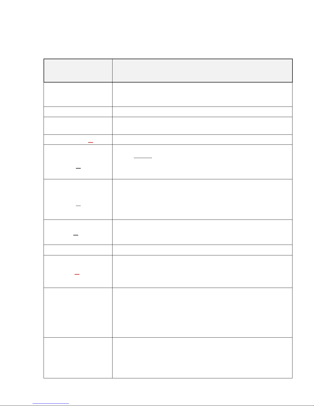
SERVICE MODE
MENU ITEMS
DESCRIPTION / COMMENTS
IF DSP
Virtual gap frequency from 5006 to 10013 Hz.
Recommended to use low-frequency virtual IF. No need to
ever change this value. DO NOT TOUCH IT.
V PWR
Adjustment of displayed voltage
REF VFO
For correcting the VFO frequency. This parameter is unitspecific for each radio. DO NOT TOUCH IT.
MULT VFO #
Divider VFO. DO NOT TOUCH IT.
BEGIN FREQUENCY
#
Sets low end starting frequency for each band. Must select
band before entering Service Mode Menu. Set the
frequency with VFO knob. Note: you must exit Service
Menu to change bands, then re-enter Service Menu to set
the next band.
END FREQUENCY
#
Sets the stop frequency for the high end of each band. Must
select band before entering Service Mode Menu. Set the
frequency with VFO knob. Note: you must exit Service
Menu to change bands, then re-enter Service Menu to set
the next band.
PORT #
(Band Ports) These port settings tell the radio which
bandpass filter and low-pass filter to use for each band.
DO NOT TOUCH IT.
S METER
Used for calibrating S-Meter Range. DO NOT TOUCH IT.
RX IQ #
Setting the mirror channel correcting the phase and
amplitude of IQ for each band separately on RX - minimum
reading – has two modes- fast and slow for quick setting
and fine – switched with STEP. DO NOT TOUCH IT.
FILTER SSB
Enables the adjustment of the high and low cut-off
frequency for each of the first three SSB filters. The range
is 150 Hz to 3600 Hz. Select filter to be adjusted by
pressing the “Filter” button. Select high or low frequency
with “RIT” button. Change cut-off frequency with the VFO
knob. Note: Filter 4 is adjusted within the normal menu
mode (not in service mode).
FILTER CW
Adjusts the bandwidth of the first three CW filters. The
range is 50 Hz to 2400 Hz. Change bandwidth by rotating
the VFO knob. Pressing the FILTER Button toggles through
filters 1, 2, & 3. Note: Filter 4 is adjusted within the normal
menu mode (not in service mode).
Page 25
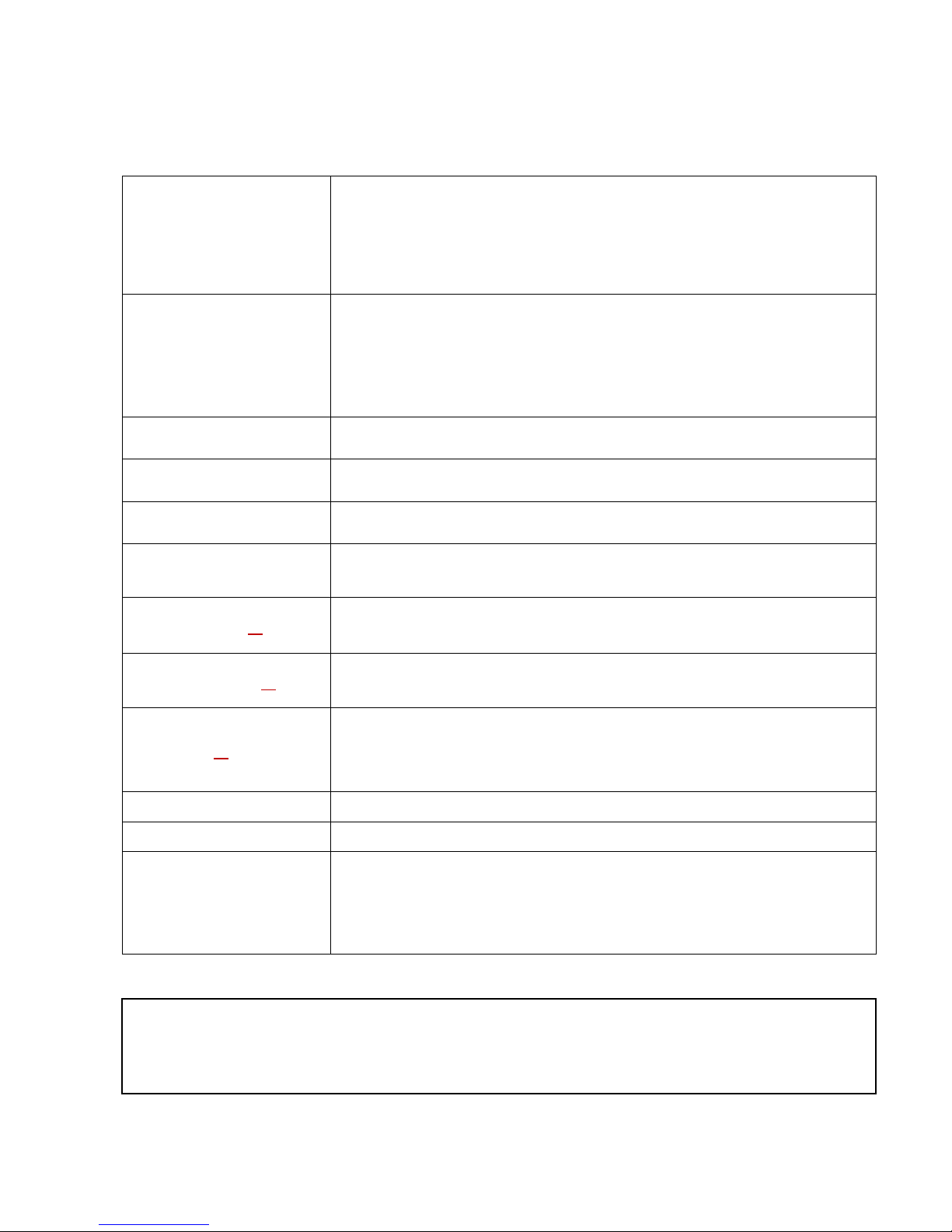
SERVICE MODE Continued:
AGC DSP
(On/Off) AGC should always be set to "ENABLE"
SHOW S METER
Switches S-Meter
FILTER TX SSB
Adjustment of transmit bandwidth in the SSB mode. Values
can be selected from 150 Hz to 3600Hz.
FILTER TX CW
Adjustment of transmit bandwidth in the CW mode. Values
can be selected from 50 Hz to 1000Hz.
FILTER TX AM
Adjustment of transmit bandwidth in the AM mode. Values
can be selected from 2000 Hz to 9600Hz.
FILTER TX FM
Adjustment of transmit bandwidth in the FM mode. Values
can be selected from 2000 Hz to 9600Hz.
LEVEL TX #
{1234} DO NOT TOUCH IT.
POWER TX #
{0} {123} DO NOT TOUCH IT.
TX IQ #
Setting the mirror channel correcting the phase and
amplitude of IQ for each band separately on TX - minimum
reading – has two modes- fast and slow for quick setting
and fine – switched with STEP. DO NOT TOUCH IT.
In the rare event that you manage to blow out some or all of the factory presets,
please contact LNR$Precision,$Inc.. The general and unique parameters of your
specific radio (by serial number) must be re-entered manually. This work takes
about one hour.
Page 26

26"
INDEX
Accessory Package: 7.
ACE: See Notch Filter; 15.
AF Gain: 8, 22.
AGC: 3, 15, 21.
AM: 13, 19, 21.
AMP KEY: 3, 5, 10.
Antenna: 3, 4, 10, 11.
Attenuator: 6, 15.
Backlight: 4, 6, 12, 21.
Band Selection: 12.
Bandscope RX: 3, 6, 16, 18.
Bandscope TX: 5, 18.
CAT Cable: 7.
CW: 3, 4, 5, 6, 8, 10, 11, 12,
13, 14, 15, 16, 18, 19, 20,
21.
CW Pitch: 13, 14, 18.
CW Speed: 20.
CW VOX: 10, 18, 20.
D.C. Power Cable: 7.
Digi Mode Gain: 5, 17.
Digi Mode: 5, 6, 13, 14, 17,
19, 21, 22.
Display: 4, 9, 12, 16.
DOWN/NB: 8, 15, 21.
Equalizer RX: 15, 22.
Equalizer TX: 17, 22.
Filter: 5, 6, 13, 14.
Filter Adjustment: 13.
Filter Selection: 13.
FM: 4, 5, 6, 13, 16, 19.
Foldback Protection: 16.
FUNCTION Button: 8.
Fuse: 4, 7.
Iambic Mode: 5, 19, 20.
Introduction: 3.
Key Type Selection: 18.
Keyer: 5, 12, 18, 19, 20.
LED Mode: 12, 21.
LINE IN/OUT: 3, 4, 7, 10, 11.
LOCK/TX: 8.
LSB: 4, 13.
Memory: 4, 14.
MENU: 8, 9, 20, 21, 22.
MENU MODE SETTINGS:
20 21, 22.
Mic Gain: 17.
Microphone: 7, 10.
Mode: 4, 5, 6, 8, 13, 17, 18,
19, 20, 21, 22.
Mode Selection: 6, 13.
Monitor:5, 17, 21.
NB: See Noise Blanker
NF: See Notch Filter
Noise Blanker: 6, 8, 11, 15,
10.
Noise Reduction: 8, 15, 20.
Notch Filter: 6, 8, 15.
NR: See Noise Reduction
Pan Level: 16, 18, 22.
Pan Adaptor: 9, 22.
Power ON/OFF: 8.
Preamp: 6, 8, 15.
PTT: 5, 10.
Reverse CW: 18, 19, 20.
RIT: 9, 11, 12, 13, 14, 15,
16, 17, 22.
RT TY: 14, 19.
Sidetone: 10, 18, 20.
Sidetone Level: 10, 18.
Smart Valcoder: 11, 20.
S-Meter: 6, 15, 21.
Software Menu Quick Guide:
22.
Speaker/SPKR: 4, 10
Specifications: 4,5,6.
Speech Compressor: 17, 19.
Speech Processor: 23.
SPLI T: 16, 17.
Squelch: 6, 16, 21.
SSB: 5, 6, 13, 14, 15, 16,
17, 20, 21, 22.
Table of Contents: 2.
Transmit Display Mode: 16
Transmit Power: 16, 21.
Tuning Modes: 11.
TX Metering: 5.
UP/NR: 8, 15.
USB: 4, 8, 13, 14, 19.
VFO/VFO Knob: 8, 9, 11, 12,
13, 14, 15, 16, 17, 18, 20.
VOX: 5, 10, 17, 18, 20, 22.
VOX Delay: 18, 22.
VOX Gain (Level): 17, 22.
Weight (CW Keyer): 5, 19,
20.
Xit: 9, 11, 12, 22.
Page 27

27"
"
"
"
"
"""""""""""""""""""""""""""""""""""""""""""""""""""""""""""""""""""""""LNR"Precision,"Inc.""
"""""""""""""""""""""""""""""""""""""""""""""1954"N"Fayetteville,"St.,""
"""""""""""""""""""""""""""""""""""""""""""""""Asheboro,"NC"27203"
Phone 336-672-1818 or cell 336 848-2743
The LD-11 Concept and Design
were created by LZ2TU, RA9YTJ, & LZ1JY
MADE IN EUROPE
for
 Loading...