

Page 1
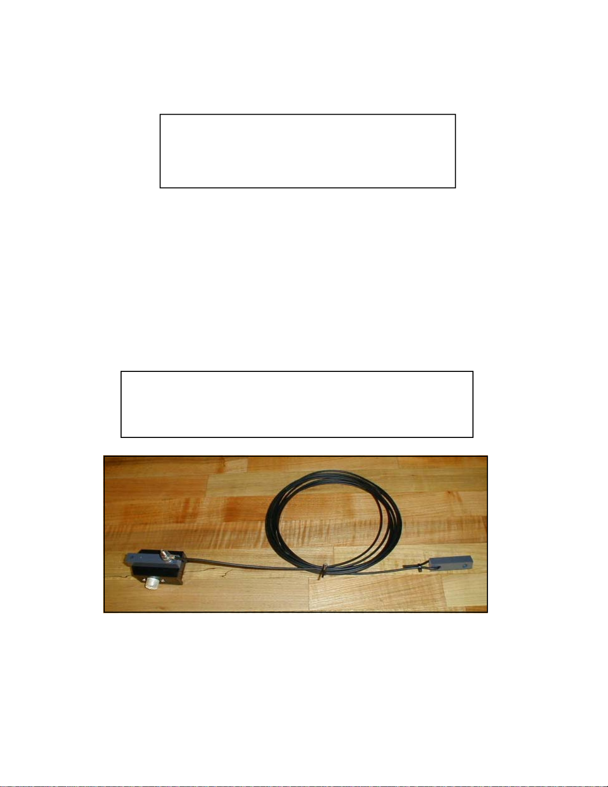
ENDFEDZ EF-17
*Patent Pending*
17M END FED DIPOLE
PARTS LIST
PART NO. QTY DESCRIPTION
SUB18001 1 17 METER EF MATCHBOX
1801 1 17M RADIATOR 25’ 6”
1802 1 17M TUNING STUB
1403 1 END INSULATOR
14417 1 #10 SPLIT RING LOCKWASHER
2814 1 #10 STAINLESS HEX NUT
2815 2 #10 STAINLESS FLATWASHER
32767 1 SHIPPING BOX
1803 1 EF-17 MANUAL
ENDFEDZ ARE MONOBAND ANTENNAS. USE ON BANDS
OTHER THAN THE DESIGN BAND WILL RESULT IN
SIGNIFICANT RADIATION FORM THE COAX AND COULD
DESTROY THE MATCHBOX
FIG. 1
Page 2
ASSEMBLY
1. This antenna is essentially a half w a ve dipole with one important difference– the feedline
is at the end of the antenna. Th e antenna is suspended at its ends by the two incl uded end
insulators– one of which is integral to the matchbox.
2 In order to have the least possible influence on the antenna, insulated lines ar e
recommended for attac hment to the insulator s. The antenna may be sus pended horizontally,
vertically or sloping. Portable operation is easily accomplished by suspending the far end from
a tree limb and letting the matchbox hang just ab ove the ground.
3. The antenna has been used from hotel rooms by hanging the matchbox end just outside the
window and letting the far end hang, or preferably pulling it away from the build ing with a
guy attached to the end insulator.
4. Tuning is best accom plished by using an antenna analyzer attached to the far end of the
coaxial cable that will be used with the antenna. O nce the i nitial resonant frequency is
established, the antenna may be tuned just like a dipole. Shortening the far end by 1” will raise
the resonant fre quency approxi m ately 50 KHz. If too much wire is removed, the included
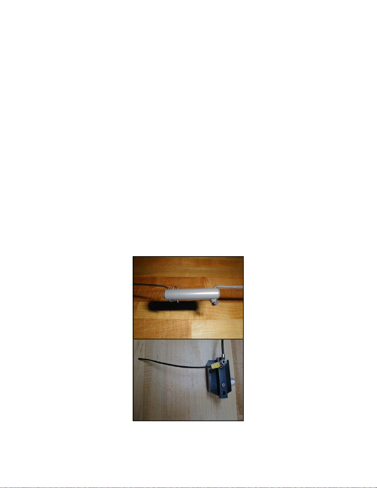
tuning stub may be attached to the 10-32 stud at the matchbox end and trimmed to establish
resonance to the desired frequency (Fig.2). Fine tuning may be accomplished by changing the
orientation of the stub with regard to the main radiator ( I.e. rotating the s tub and retightening
the hardware. Tighten the #10 hardware just e nough to compress the lock washer
5. Once you are satisfied with the overall length of the radiator, lace the wire through all three
holes in the insulator as shown in Fig. 1.
6. Fig. 3 illustrates some mounting ideas.
Fig. 1
Fig. 2
Page 3
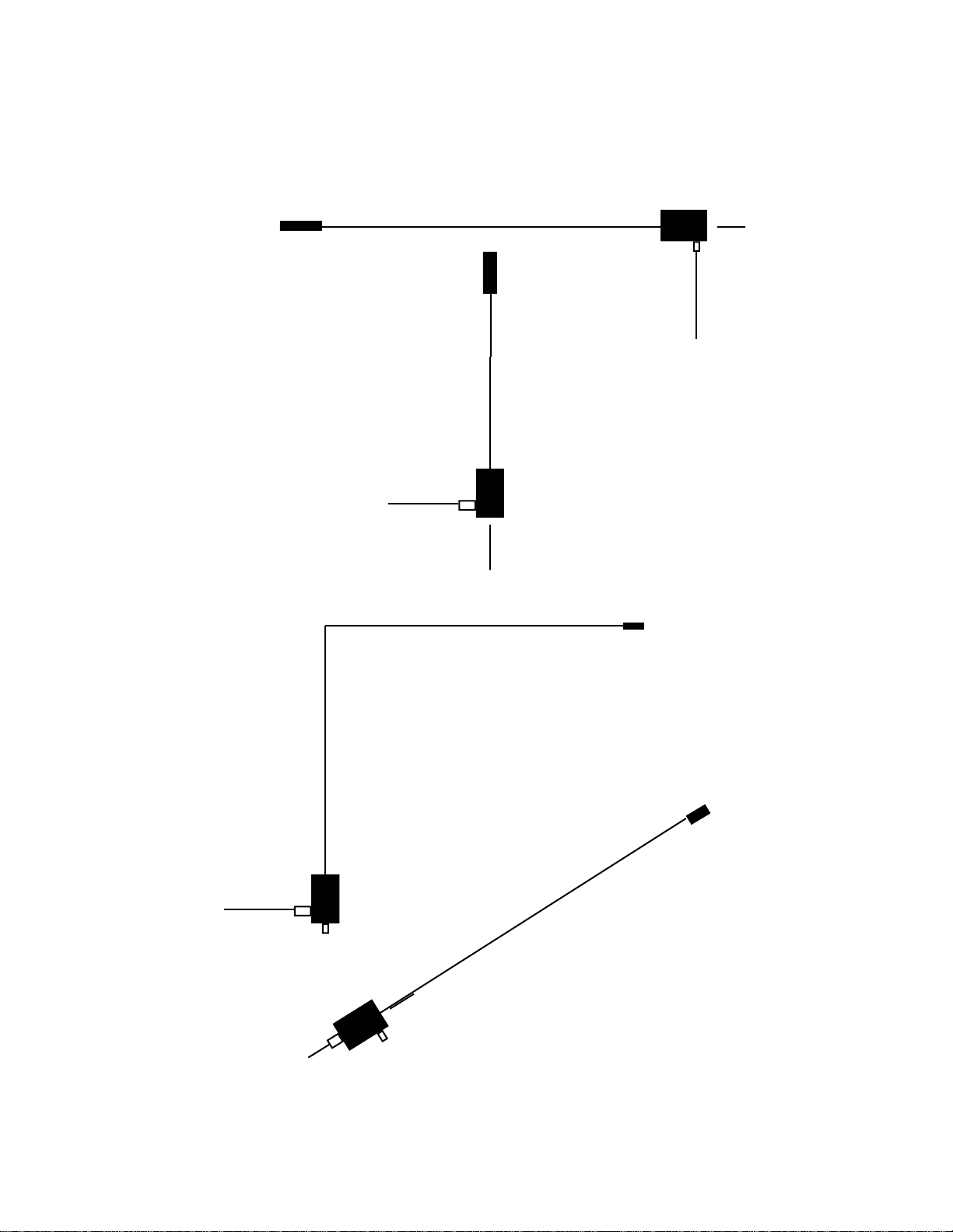
GUY
RADIATOR
GUY
COAX
RADIATOR
COAX
GUY– IF NECESSARY
INVERTED L
SLOPER
Page 4
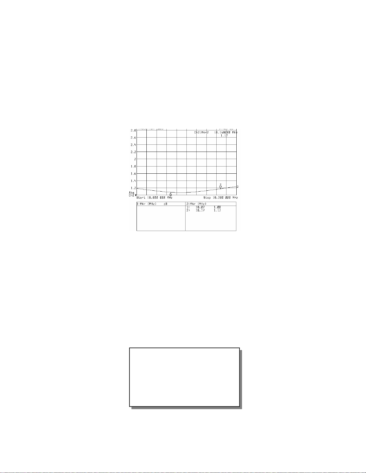
EF-17
TYPICAL
V.S.W.R. PLOT
SPECIFICATIONS
Polarity: Depends on mounting configuration
Design Z: 50 Ohms
V.S.W.R. Bandwidth: 400KHz 1.5:1
Power Handling: 100W
Weight: 0.5 lbs
Length: 25’ 6”
Hardware: Stainless Steel
Connector: Silver/Teflon SO-239
Radiator: #14 black poly coated Flex Weave
 Loading...